

Page 1

Register your product and get support at:
www.philips.com/welcome
SDV4401/27
EN Outdoor antenna 2
FR Antenne extérieure 9
ES Antena para exteriores 16
Page 2

Table of Contents
1. Important 3
2. Your outdoor antenna
2.1 What’s in the box
2.2 What you’ll also need
3. Installing your antenna
3.1 Splinting the Main Boom Sections
Together
3.2 Mast Clamp Assembly
3.3 Support Boom Assembly
3.4 UHF Dipole and Isolation Network
Assembly
3.5 Connecting Lead-In Cable to the
Antenna
3.6 Unfolding the Antenna Elements
3.7 Attaching to the Mast
3.8 Routing the Cable to Your TV/FM
Receiver
4. Wall mounting your antenna
5. Warranty & Service
(mast not included) 7
3
4
4
5
5
5
5
6
6
6
7
8
8
2
Page 3

1 Important
2 Your outdoor antenna
Take time to read this manual before you use
your outdoor antenna. It contains important
information and notes regarding operating
your outdoor antenna.
© 2008 Koninklijke Philips Electronics N.V.
All rights reserved. Reproduction in whole or in
part is prohibited without the written consent of
the copyright owner. Trademarks are the
property of Koninklijke Philips Electronics N.V.
or their respective owners.
B Warnings
• Make sure these instructions are read
and thoroughly understood before
attempting installation. If you are
unsure of any part of this installation,
contact a professional installer for
assistance or contact Customer Service
at 1-919- 573-7854.
• When you install your antenna, use
extreme caution. If the antenna
starts to fall, let it go! It could contact
overhead power lines. If the antenna
touches the power line, contact with the
antenna, mast, cable, or guy wires can
cause electrocution and death. Call the
power company to remove the antenna.
Do not attempt to remove it yourself.
• Safety gear and proper tools must
be used. Failure to do so can result in
property damage and/or serious injury.
• For installation outdoors, we
recommend two people assemble the
entire antenna on the ground, then
mount the assembled antenna on the
mast. For installation in an attic, rst
measure the attic space to make sure
the assembled antenna will t; you
might need to perform the assembly in
the attic, since it might not t through
the attic entrance.
Congratulations on your purchase and welcome
to Philips!
To fully benet from the support that Philips
offers, register your product at
www.philips.com/welcome.
ENGLISH
3
Page 4
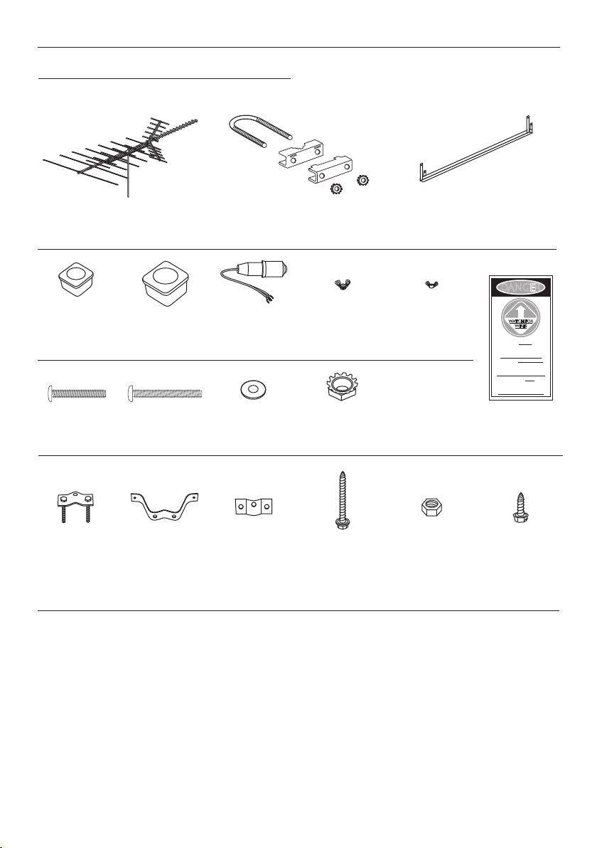
2.1 What’s in the box
DANGER
WATCH FOR
WIRES
You can be KILLED if this
product comes near
electric power lines.
READ INSTRUCTIONS
Usted puedo SER MATADO si
este producto viene cerca de
lineas de la energia eléctrica.
LEA LAS INSTRUCCIONES
ll y a danger de mort si ce
produit entre en contact
avec des fils électriques.
LIRE LES INSTRUCTIONS
Mast mounting hardware
Small 13/16" wing
boom end plugs
(2)
Large 1" main
boom & support
boom end plugs
(4)
1 1/4" 10-32
machine screws
(2)
1 1/2" 10-32
machine screws
(6)
Wall mounting hardware
Wall brackets (2)Mounting clamp
assemblies (2)
* Extra parts may be included
2.2 What you’ll also need.
U-Bolt (2), Mast Clamp (2), Mast Clamp
Back-up plate (2), Lock Nuts (4)
Matching 300
to 75 ohm
transformer (1)
#10 flat washers
(4)
Reinforcing plates
Large 10-32
wing nuts
(7/8" wing span)
(10)
1
/4 - 20 lock nuts
(4)
2" lag screws (4) 1/4" x 20 nuts (4) 3/4" tap screw (1)
(2)
Support BoomAntenna (1)
Small 10-32
wing nuts
(3/4" wing span) (2)
Tri-Lingual
Warning Label
• Flat head screwdriver
• Ratchet or driver with 1/2" (13 mm) socket
• Portable or electric drill
• 1/4" (6 mm) drill bit and stud nder for drywall installation
• 3/8" (10 mm) masonry bit for concrete installation
4
Page 5
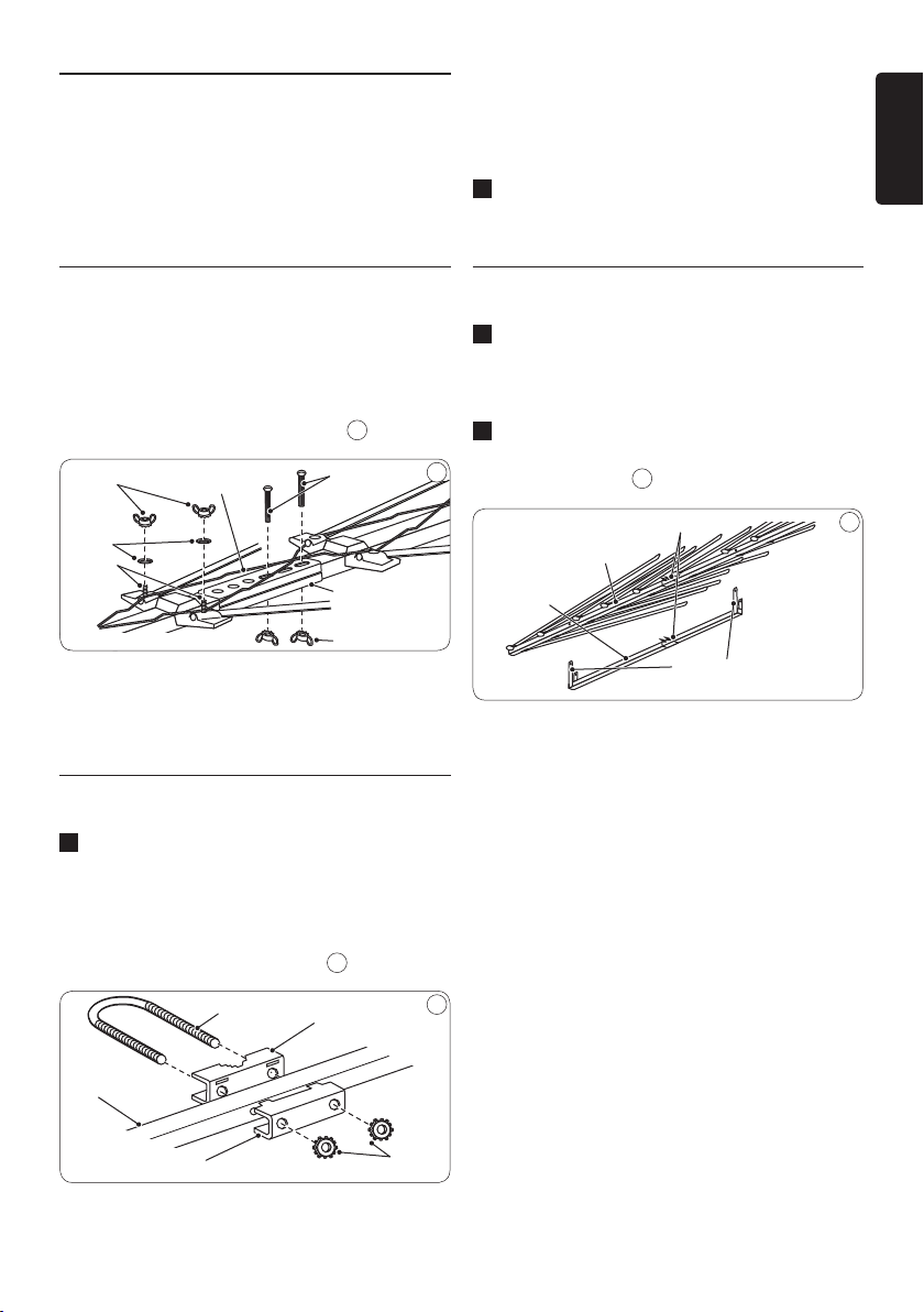
3 Installing your antenna
Large Wing Nuts
Flat
Washers
Threaded
Posts
Crossover
Wires
Splint
Large Wing Nuts
1
1
/
2
-Inch Screws
U-Bolt
Mast Clamp
Lock Nuts
Backup Plate
Main Boom
Mast Clamps
Main Boom
Support Straps
Support
Boom
B Warning
Installation of this product is dangerous. For
your safety, follow the installation directions.
D Note
To access the mast clamp holes, move the
antenna’s elements out of the way as needed.
ENGLISH
2 Press the supplied large end plugs into
the main boom and support boom.
3.1 Splinting the Main Boom
Sections Together
Use the supplied hardware to assemble the main
boom sections. If necessary, lift one end of the
main boom so the crossover wires reach the
threaded posts of the next section. 1
1
D Note
There are no crossover wires over the back section.
3.2 Mast Clamp Assembly
1 Use the supplied hardware to loosely attach
the U-bolt and lock nuts to the mast clamp
assembly on the main boom as shown.
Attach the support boom’s mast clamp,
facing it the same direction as the main
boom’s mast clamp assembly. 2
3.3 Support Boom Assembly
1 Align the support boom’s straps and mast
clamp with the main boom’s support strap
holes and mast clamp.
2 Attach the support straps to the main boom
using the two supplied 1½-inch screws and
large wing nuts. 3
3
2
5
Page 6

3.4 UHF Dipole and Isolation
UHF Dipole
Isolation Network
Main Boom
Lead-in Terminal
Lead-in Terminals
Matching Transformer
Flat Washers
Wing Nuts
Weather Boot
Coax Cable
F-Connector
Plastic Strain-Relief Tab
Spade Terminal Ends
Wing B
Element
Small Wing Nuts
Wing Boom
Wing Boom
11/4- Inch Screws
Network Assembly
1
Pull the two halves of the UHF dipole away
from the main boom until they lock into the
support bracket.
2 Place each half’s unattached end over one of
the antenna’s lead-in terminals (one for each
half of the UHF dipole on each side of
the boom). 4
D Note
Both bars of the isolation network should
remain parallel to the main boom.
4
3.5 Connecting Lead-In Cable
to the Antenna
D Note
If you prepare your own cable, slide the supplied
matching transformer’s weather boot onto the
cable before you attach the F-connector.
3
Screw the cable’s F-connector onto
the matching transformer. Then slip the
weatherboot over the connection.
D Note
If you use a cable without a weatherboot, cover
the connection with weatherproof tape. 5
3.6 Unfolding the Antenna Elements
1 Hold each UHF wing boom and turn its
elements until they snap squarely into place
(perpendicular to the boom).
2 Press the supplied small end plugs into the
ends of the wing booms.
Fold out the wing booms and secure them
3
into position using the two supplied 1¼-inch
screws and wing nuts. 6
5
6
We recommend RG-6 cable, and if you prepare
your own cable, use a quality F-connector.
1 Thread the supplied matching transformer’s
spade terminal ends through the antenna’s
strain-relief tab.
2 Slide the spade terminal ends around
the antenna’s lead-in terminals marked
CONNECT LEAD-IN HERE. Secure them
with the supplied at washers and large
wing nuts.
6
4 Hold the main boom’s elements near the
pivot points and pull them away from the
boom until they snap into the locking
support brackets.
Page 7

D Note
Support Bracket
Support Boom
Mast
Mast Clamp
Crossover Wires
Main Boom
Toward TV Station
You may wait to unfold the elements until you
get the antenna up on the roof or in your attic.
B Warning
Do not pull the elements near their outer ends
or you could damage them.
ENGLISH
3.7 Attaching to the Mast
(mast not included)
We recommend you get the help of another
person before you put up the mast or attach
your antenna to it. How you set up your mast
depends on your specic installation.
Refer to the separate Consumer Product
Safety Commission Information for
recommended methods.
Slide the antenna’s mast clamp assemblies
1
over the end of the mast, with the main
boom plastic brackets on top, and the
support boom under it.
2 Tighten the mast clamp assemblies' lock
nuts to hold the antenna in place. Do not
overtighten the lock nuts.
B Warning
The crossover wires must not touch the
antenna boom, the mast, or each other.
If necessary, carefully bend the crossover wires
to provide at least 1/2 inch of clearance. 7
D Note
You can also put the antenna in an attic space.
You can mount it from a rafter or place
the antenna on the attic oor. However, we
recommend you use mounting hardware for a
secure attic installation.
3.8 Routing the Cable to Your TV/FM
Receiver
1 Use plastic tape to secure the coaxial cable
to the mast at about 3-foot intervals.
2 Use coaxial nail clips every few feet to
secure the cable between the mast and
where the cable enters the house.
3 Use a 75 ohm grounding block at the point
where the cable enters the house. Read
the separate Consumer Product Safety
Commission Information for
grounding instructions.
4 Make a drip loop with the cable before it
7
enters the house to avoid water following
along the cable.
antenna’s shortest elements point toward
3 Set up the mast, then rotate it so the
the stations you want to receive. Then
secure the mast into position.
5 Use a wall-through tube to neatly route the
coaxial cable through the walls.
6
Use only the length of cable that your
installation requires. Do not coil extra cable
behind the receiver. Cut it to the
correct length.
7
Page 8

4 Wall mounting your antenna
Reinforcing plates
Hex nuts
2” lag screws
Pilot Hole
3/4” tap screw
Mounting clamps
Wall brackets
5 Warranty & Service
1
Attach mounting clamps behind wall brackets,
and thru reinforcing plates, with bolts facing
out. Do not tighten. 7
2 Secure the assembled wall mount to wall
with lag screws making sure brackets are
approximately 2 ft. apart and vertically aligned.
3 Insert mast (not included) and assembled
antenna through both mounts, checking
to see that the mast is aligned vertically
(straight). Tighten hex-nuts securely.
To prevent the mast from turning, drill a
4
13/64" hole in mast through the pilot hole of
one of the mounting clamps. Insert 3/4" selftapping screw and tighten.
Limited One-Year Warranty
Philips warrants that this product shall be free
from defects in material, workmanship and
assembly, under normal use, in accordance with
the specications and warnings, for one year
from the date of your purchase of this product.
This warranty extends only to the original
purchaser of the product, and is not transferable.
To exercise your rights under this warranty, you
must provide proof of purchase in the form of
an original sales receipt that shows the product
name and the date of purchase. For customer
support or to obtain warranty service, please
call 919-573-7854. THERE ARE NO OTHER
EXPRESS OR IMPLIED WARRANTIES. Philips’
liability is limited to repair or, at its sole option,
replacement of the product. Incidental, special
and consequential damages are disclaimed
7
where permitted by law. This warranty gives
you specic legal rights. You may also have other
rights that vary from state to state.
For technical support, send us an email with the
model number of the product and a detailed
description of your problem to:
accessorysupport@philips.com
8
Page 9

Table des matières
1. Consignes de sécurité
importantes 10
2. Votre antenne extérieure 10
2.1 Contenu de la boîte 1
2.2 Outils requis 1
3. Installation de votre antenne 12
3.1 Assemblage des sections de la èche
principale 1
3.2 Assemblage de colliers du mât 1
3.3 Assemblage de èche de soutien 1
3.4 Assemblage du réseau d’isolation et
du dipôle UHF 1
3.5 Connexion du câble d’entrée à
l'antenne 1
3.6 Déploiement des éléments de
l'antenne 1
3.7 Fixation au mât
3.8 Acheminement du câble à votre
récepteur FM ou à votre téléviseur 1
4. Montage mural de votre antenne 15
5. Garantie et services 15
(mât non inclus) 14
1
1
FRANÇAIS
2
2
2
3
3
3
4
9
Page 10

10
1 Consignes de sécurité
2 Votre antenne extérieure
importantes
Lisez ce manuel attentivement avant d’utiliser
votre antenne extérieure. Il contient des
informations importantes concernant l’utilisation
de votre antenne.
© Koninklijke Philips Electronics N.V., 2008.
Tous droits réservés. La reproduction de la
totalité ou d’une partie du présent manuel est
interdite sans l’autorisation écrite du titulaire du
droit d’auteur. Les marques de commerce sont la
propriété de Koninklijke Philips Electronics N.V.
ou de leur détenteur respectif.
B Avertissements
• Assurez-vous de bien comprendre
les instructions avant d'installer le
support mural. Si vous n'êtes pas
certain de bien comprendre une étape,
consultez un installateur professionnel
ou communiquez avec le service à la
clientèle, au 1 (919) 573-7854.
• Lors de l'installation de votre antenne,
prenez toutes les précautions. Si votre
antenne commence à tomber, ne tentez
pas de la rattraper! Elle pourrait entrer
en contact avec les lignes à haute
tension. Si l'antenne touche une ligne
électrique, tout contact avec l'antenne,
le mât, le câble ou les câbles de hauban
pourrait entraîner une électrocution et
causer la mort. Communiquez avec la
compagnie d'électricité an qu'elle retire
l'antenne. N'essayez jamais de la retirer
vous-même.
• Pour réduire les risques de dommages
matériels et de blessure, portez
l'équipement de sécurité nécessaire et
utilisez les outils appropriés.
• Pour une installation à l’extérieur, nous
recommandons que deux personnes
assemblent entièrement l'antenne au
sol, puis qu'elles xent ensuite l'antenne
assemblée au mât. Pour une installation
à l’intérieur, mesurez tout d'abord
les combles an de vous assurer que
l'antenne une fois assemblée pourra y
être installée; vous devrez probablement
effectuer le montage sur place car il se
peut que l'antenne ne puisse pas passer
par la porte du grenier ou des combles.
Félicitations pour votre achat et bienvenue dans
le monde Philips!
Pour bénécier pleinement de l’assistance
offerte par Philips, enregistrez votre produit sur
le site www.philips.com/welcome.
Page 11

2.1 Contenu de la boîte
DANGER
WATCH FOR
WIRES
You can be KILLED if this
product comes near
electric power lines.
READ INSTRUCTIONS
Usted puedo SER MATADO si
este producto viene cerca de
lineas de la energia eléctrica.
LEA LAS INSTRUCCIONES
ll y a danger de mort si ce
produit entre en contact
avec des fils électriques.
LIRE LES INSTRUCTIONS
Matériel de montage du mât
Boulon en U (2), collier de mât (2),
plaque de fixation du collier de mât (2),
contre-écrous (4)
Petites prises
d'extrémité de
flèche de 3/16 po
(2)
Vis à métaux
1
/4 po 10-32 (2)
1
Grosses prises
d'extrémité de
flèche de soutien et
de flèche principale
de 1 po (4)
Vis à métaux
1
/2 po 10-32 (6)
1
Transformateur
de 300 à 75 ohm
(1)
Rondelles plates
nº 10 (4)
Matériel de montage mural
Ensembles de
bride de
fixation (2)
Fixations
murales (2)
Plaques de
renfort (2)
* Les pièces supplémentaires peuvent être incluses
Gros écrous
à ailettes 10-32
(portée 7/8 po)
(10)
Contre-écrou
1
/4 - 20 (4)
Tire-fond de
2 po (4)
Bras de supportAntenne (1)
Petits écrous
à ailettes 10-32
(portée 3/4 po) (2)
Écrous
1/4 po x 20 (4)
FRANÇAIS
Étiquette
d’avertissement
en trois langues
Vis d’assemblage
de 3/4 po (1)
2.2 Outils requis
• Tournevis cruciforme
• Clé à cliquet ou broche mandarin avec douille de 1/2 po (13 mm)
• Perceuse portative ou électrique
• Foret de 1/4 po (6 mm) et détecteur de montant pour l'installation sur cloison sèche
• Foret de maçonnerie de 3/8 po (10 mm) pour l'installation sur béton
11
Page 12

12
3 Installation de votre antenne
Gros écrous à ailettes
Rondelles
plates
Entretoises
filetées
fils électriques
croisés
Gouttière
Gros écrous
à ailettes
Vis de 1
1
/
2
po
Boulon en U
Collier de mât
Contre-écrous
Plaque de fixation
Flèche principale
Colliers de mât
Flèche principale
Courroies de soutien
Flèche de
soutien
B Avertissement
L'installation de ce produit est dangereuse.
Pour votre sécurité, veuillez suivre les
instructions d'installation.
3.1 Assemblage des sections
de la èche principale
Utilisez le matériel fourni afin d'assembler les
sections de la flèche principale. Au besoin,
relevez une extrémité de la flèche principale
afin que les fils électriques croisés atteignent les
entretoises filetées de la section suivante. 1
D Remarque
Au besoin, bougez les éléments de l'antenne an
d'accéder aux trous de collier de mât.
2 Enfoncez les bouchons larges dans le
bras principal et dans le bras de support.
3.3 Assemblage de èche de soutien
1 Alignez les courroies et les colliers de mât
de la èche de soutien vis-à-vis des trous de
courroies de soutien et de colliers de mât
de la èche principale.
2
Attachez les courroies de soutien à la èche
principale à l'aide des vis de 1 ½ po et des
gros écrous à ailettes. 3
D Remarque
Il n'y a aucun fil électrique croisé sur la section arrière.
3.2 Assemblage de colliers du mât
1 Utilisez le matériel fourni an de xer, sur
la èche principale, le boulon en U et les
contre-écrous aux colliers du mât sans les
serrer complètement, tel qu'indiqué sur
l'illustration ci-dessous. Fixez le collier de
mât de la èche, en face de l'assemblage de
colliers et dans la même direction. 2
1
2
3
Page 13

3.4 Assemblage du réseau d’isolation et
Dipôle UHF
Réseau d'isolation
Flèche principale
Borne d'entrée
Bornes d'entrée
Transformateur
Rondelles plates
Écrous à ailettes
Gaine d’étanchéité
Câble coaxial
Connecteur F
Languette de
plastique antitraction
Extrémités de la
borne embrochable
éléments
de flèches
Petits écrous à ailettes
flèches
flèches
Vis de 11/4 po
du dipôle UHF
1
Éloignez les deux moitiés du dipôle UHF
de la èche principale jusqu'à ce qu'ils se
verrouillent dans le support de xation.
Placez chaque extrémité non attachée de
2
moitié sur une des bornes d'entrée de
l'antenne (une pour chaque moitié du dipôle
UHF sur chaque côté de la èche).
4
D Remarque
Les broches du réseau d'isolation doivent rester
parallèles à la èche principale.
4
3.5 Connexion du câble d’entrée à
l'antenne
Nous vous recommandons d'utiliser un
câble RG-6 et, si vous préparez votre propre
câble, veuillez utiliser un connecteur F de qualité.
3
Vissez le connecteur F du câble dans le
transformateur. Puis faites glisser la gaine
d’étanchéité sur la connexion.
D Remarque
Si vous utilisez un câble dépourvu de gaine
d'étanchéité, recouvrez la connexion de ruban
adhésif étanche. 5
3.6 Déploiement des éléments de
l'antenne
1 Maintenez chaque èche UHF et tournez
ses éléments jusqu'à ce qu'ils se mettent
parfaitement en place (perpendiculairement
à la èche).
2 Entrez les ches à bout étroit dans les
extrémités des èches.
3 Plier les èches et assurez leur
positionnement en utilisant les deux vis de
1 ¼ po et les deux écrous à ailettes.
6
5
FRANÇAIS
D Remarque
Si vous préparez votre propre câble, faites glisser
la gaine d’étanchéité du transformateur fourni
sur le câble avant d'attacher le connecteur F.
1
Enlez les extrémités de la borne
embrochable du transformateur dans
la languette de plastique antitraction de
l'antenne.
2
Faites glisser les extrémités de la borne
embrochable autour des bornes d'entrée de
l'antenne portant la mention « CONNECT
LEAD-IN HERE » (Connecter le câble ici).
Assurez leur xation grâce aux rondelles
plates et aux gros écrous à ailettes fournis.
6
4 Maintenez les éléments de la èche
principale proche des axes de pivotement et
éloignez-les jusqu'à ce qu'ils se mettent en
place dans les supports de xation.
13
Page 14

14
D Remarque
Support de fixation
Flèche de soutien
Mât
Collier de mât
fils électriques croisés
Flèche principale
Vers la station de télé
Il se peut que vous deviez attendre avant de
déployer les éléments que l'antenne soit sur le
toit ou dans les combles.
B Avertissement
Ne tirer pas les éléments près de leur extrémité
externe car vous pourriez les endommager.
3.7 Fixation au mât
(mât non inclus)
Nous vous conseillons de demander l'aide d'une
autre personne avant de dresser le mât ou d'y
xer votre antenne. Le réglage du mât dépend
de votre type d'installation. Référez-vous aux
indications de la Commission de la sécurité
des produits de consommation relatives aux
différentes méthodes recommandées.
Faites glisser les colliers de mât vers
1
l'extrémité de celui-ci, en orientant les
attaches de plastique du bras principal vers
le haut et le bras de support en dessous.
2 Serrez les contre-écrous de l'assemblage
de colliers an de maintenir l'antenne bien
en place. Ne serrez pas plus qu'il ne faut les
contre-écrous.
B Avertissement
Les ls électriques croisés ne doivent pas se toucher
ou entrer en contact avec la èche d'antenne ou le
mât. Au besoin, pliez les ls électriques croisés an
d'assurer un jeu de 4 po.
3 Fixez le mât, puis faites-le pivoter an que
ses plus petits éléments soient en direction
des stations dont vous voulez capter les
émissions. Puis assurez son positionnement.
7
D Remarque
Vous pouvez également installer l'antenne sous
les combles. Vous pouvez la xer à des poutres
ou la poser sur le sol. Cependant, nous vous
recommandons d'utiliser le matériel de montage
pour vous assurer d'une installation sous
combles sécurisée.
3.8 Acheminement du câble à votre
récepteur FM ou à votre téléviseur
1 Utilisez du ruban adhésif tous les 3 pi
environ an d'assurer le câble coaxial
jusqu'au mât.
2 Puis posez des agrafes à clou tous les pieds
an de sécuriser le câble depuis le mât
jusqu'à l'endroit où il entre dans la maison.
3 Installez un bloc de mise à la terre de
75 ohm à l'endroit où le câble entre dans
la maison. Veuillez lire les instructions
spéciques de la Commission de la sécurité
des produits de consommation
concernant la mise à la terre.
Faites une boucle d'égouttement avec le
4
7
câble avant qu'il n'entre dans la maison an
d'éviter que de l'eau ne s'inltre en suivant
le câble.
5 Utilisez un guide-câbles an d'acheminer
correctement le câble coaxial dans les murs.
6 Utilisez uniquement la longueur de
câble dont vous avez besoin pour votre
installation. N'enroulez pas un surplus de
câble derrière votre téléviseur. Coupez-le
à bonne longueur.
Page 15

4 Montage mural de votre
Plaques de renfort
Écrous hexagonaux
Tire-fond de 2po
Avant-trou
Vis d’assemblage
de 3/4po
Brides de fixation
Fixations murales
antenne
1
Fixez les brides derrière les xations
murales puis à travers les plaques de renfort,
les boulons vers l'extérieur. Ne serrez pas
les boulons. 7
2 Serrez la xation murale au mur avec
des tire-fond, en veillant à ce qu'ils soient
parallèles verticalement et séparés d'environ
60 cm.
3 Insérez le mât (en sus) et l'antenne dans les
deux supports, en vous assurant que le mât
est bien droit, puis serrez les écrous.
Pour empêcher la rotation du mât, percez
4
un trou de 13/64 po dans l'avant-trou de
l'une des brides de xation, insérez-y une vis
autotaraudeuse de 3/4 po puis serrez-la.
5 Garantie et services
Garantie limitée de un an Philips garantit que ce
produit ne présentera aucun défaut de matériau,
de main-d’œuvre ou de fabrication, dans des
conditions normales d’utilisation conformes
aux spécications et aux avertissements,
pendant un an à compter de la date d’achat du
produit. Cette garantie s’applique uniquement
à l’acquéreur initial du produit et n’est pas
cessible. Pour exercer vos droits dans le cadre
de cette garantie, vous devez fournir le reçu
de caisse original sur lequel gure le nom du
produit et la date d’achat. Pour communiquer
avec le service à la clientèle ou obtenir des
services en vertu de la garantie, composez
le 1 (919) 573-7854. IL N’EXISTE AUCUNE
GARANTIE EXPRESSE OU IMPLICITE. La
responsabilité de Philips se limite à la réparation
7
ou, à sa discrétion, au remplacement du produit.
Philips décline toute responsabilité quant aux
dommages accidentels, spéciaux ou induits,
lorsque la loi l’autorise. Cette garantie vous
confère des droits juridiques spéciques. Vous
pouvez également bénécier d’autres droits, qui
varient selon les pays.
FRANÇAIS
Pour obtenir du soutien technique,
envoyez un courriel indiquant le numéro
de modèle de l’antenne et une description
détaillée du problème à l’adresse suivante :
accessorysupport@philips.com
15
Page 16

Índice
1. Importante 17
2. Antena para exteriores 17
2.1 Contenido del kit 1
2.2 Otros elementos necesarios 1
3. Instalación de la antena 19
3.1 Unión de las secciones del brazo
principal mediante el uso de una tablilla 1
3.2 Montaje de la abrazadera del soporte 1
3.3 Montaje del brazo de soporte 1
3.4 Montaje del dipolo UHF y el circuito
de aislamiento 2
3.5 Conexión del cable de bajada a
la antena 2
3.6 Despliegue de la antena 2
3.7 Colocación en el soporte 2
(soporte no includio)
3.8 Direccionamiento del cable hacia el
receptor de TV/FM 2
4. Montaje de la antena en la pared 22
5. Garantía y servicio técnico 22
8
8
9
9
9
0
0
0
1
1
16
Page 17

1 Importante
2 Antena para exteriores
Lea este manual detenidamente antes de
utilizar la antena para exteriores, pues contiene
información y notas importantes acerca de
su utilización.
© 2008 Koninklijke Philips Electronics N.V.
Todos los derechos reservados. Queda prohibida
la reproducción total o parcial sin la autorización
escrita del titular de los derechos de propiedad
intelectual. Las marcas comerciales son propiedad
de Koninklijke Philips Electronics N.V. o de sus
respectivos titulares.
B Advertencias
• Lea las instrucciones con detenimiento
antes de comenzar la instalación. Si tiene
dudas, comuníquese con un instalador
profesional o con el servicio de atención
al cliente al 1-919-573-7854.
• Al instalar la antena, tome todas las
precauciones necesarias. Si comienza a
caerse, no intente sujetarla, ya que puede
entrar en contacto con cables eléctricos. De
ser así, el contacto con la antena, el soporte,
el cable o los cables de sujeción puede
causar electrocución e incluso la muerte.
Comuníquese con la empresa de energía
para retirar la antena. No intente quitarla
por cuenta propia.
• Utilice equipos de seguridad y herramientas
apropiadas. De no hacerlo, podría ocasionar
serios daños materiales o sufrir
lesiones graves.
• Para instalaciones en exteriores, se
recomienda que dos personas armen la
antena en el suelo y, una vez ensamblada,
la coloquen sobre el soporte. Para
instalaciones en áticos, en primer lugar
mida el espacio disponible para asegurarse
de que sea suciente para colocar la antena
ensamblada. Es probable que tenga que
armarla dentro del ático ya que es posible
que no pase por la entrada.
Felicitaciones por su compra y bienvenido a
Philips.
Para utilizar los servicios de asistencia técnica de
Philips, registre su producto en
www.philips.com/welcome.
ESPAÑOL
17
Page 18

2.1 Contenido del kit
DANGER
WATCH FOR
WIRES
You can be KILLED if this
product comes near
electric power lines.
READ INSTRUCTIONS
Usted puedo SER MATADO si
este producto viene cerca de
lineas de la energia eléctrica.
LEA LAS INSTRUCCIONES
ll y a danger de mort si ce
produit entre en contact
avec des fils électriques.
LIRE LES INSTRUCTIONS
Accesorios para montaje en soporte
Perno en U (1), abrazadera de soporte
(1), placa de soporte de la abrazadera
de soporte (1), tuercas (2)
Tapones
terminales de
brazos tipo ala
pequeños de
3
/16" (2)
Tornillos
roscados 10-32
de 1 1/4" (2)
Brazo principal
grande de
1" y tapones
terminales de
brazos de soporte
(4)
Tornillos
roscados 10-32
de 1 1/2" (7)
Transformador de
adaptación de 300
a 75 ohmios (1)
Arandelas planas
Nº 10 (5)
Accesorios para montaje en pared
Grampas de
montaje (2)
Soportes de
pared (2)
Placas de
refuerzo (2)
* Las piezas adicionales pueden ser incluidas
2.2 Otros elementos necesarios.
Tuercas mariposa
10-32 grandes
(ancho de ala de
7
/8") (10)
Tuerca 1/4 - 20 (2)
Tirafondos
de 2" (4)
Brazo de soporteAntena (1)
Tuercas mariposa
10-32 pequeñas
(ancho de ala de
3
/4") (3)
Tuercas de
1/4" x 20 (4)
Tres idiomas
Etiqueta de
advertencia
Tornillo macho
de 3/4” (1)
• Destornillador de cabeza plana
• Trinquete o llave con toma de 13 mm (1/2")
• Taladro portátil o eléctrico
• Broca de 6 mm (1/4”) y detector de vigas para instalación en paredes de cartón yeso
• Broca de 10 mm (3/8") para instalaciones en paredes de hormigón
18
Page 19

3 Instalación de la antena
Tuercas mariposa
grandes
Arandelas
planas
Postes
roscados
Cables cruzados
Tablilla
Tuercas mariposa
grandes
Tornillos de
1
1
/ pulg
Perno en U
Abrazadera del soporte
Tuercas
Placa de soporte
Brazo principal
Abrazaderas del soporte
Brazo principal
Fleje de sujeción
Brazo de
soporte
B Advertencia
La instalación de este producto conlleva riesgos.
Siga las instrucciones para proteger su seguridad.
3.1 Unión de las secciones del brazo principal
mediante el uso de una tablilla
Utilice los accesorios suministrados para montar
las secciones del brazo principal. De ser necesario,
eleve uno de los extremos del brazo principal
de manera que los cables cruzados alcancen los
postes roscados de la siguiente sección. 1
1
D Nota
La sección posterior no presenta cables cruzados.
D Nota
Para acceder a los oricios de la abrazadera del
soporte, retire los elementos de la antena que
pueden interferir según sea necesario.
2
Presione los tapones terminales grandes
suministrados contra el brazo principal y
de soporte.
3.3 Montaje del brazo de soporte
1 Alinee el eje del brazo de soporte y la
abrazadera del soporte con los oricios
del eje de sujeción del brazo principal y la
abrazadera del soporte.
Sujete los ejes de sujeción al brazo
2
principal con las tuercas mariposa grandes
y los dos tornillos de 1½ pulgadas
suministrados. 3
ESPAÑOL
3
3.2 Montaje de la abrazadera del soporte
1
Utilice los elementos suministrados para
colocar el perno en U y las tuercas en la
abrazadera del soporte del brazo principal
tal como se indica en la ilustración, sin
ajustarlos. Coloque la abrazadera del
soporte de manera que apunte en la misma
dirección que el montaje de la abrazadera
del soporte del brazo principal.
2
2
19
Page 20

3.4 Montaje del dipolo UHF y el circuito
Dipolo UHF
Circuito de aislamiento
Brazo principal
Terminal de bajada
Terminales de bajada
Transformador de adaptación
Arandelas planas
Tuercas mariposa
Mango aislador contra la intemperie
Cable coaxial
Conector tipo F
Solapa plástica
protectora
Extremos
terminales
Elemento B
del ala
Tuercas mariposa
pequeñas
Brazo tipo ala
Brazo tipo ala
Tornillos de 11/4 pulg
de aislamiento
1 Separe las dos mitades del dipolo UHF
del brazo principal hasta que alcancen el
soporte.
2 Coloque el extremo suelto de cada una de
las mitades sobre uno de los terminales de
bajada de la antena (uno por cada mitad del
dipolo UHF a cada lado del
brazo).
4
D Nota
Ambas barras del circuito de aislamiento deben
permanecer paralelas al brazo principal.
3.5 Conexión del cable de bajada a la antena
3
Atornille el conector tipo F del cable
al transformador de adaptación. A
continuación, coloque el mango aislador
sobre la conexión.
D Nota
Si utiliza un cable sin un mango aislador, cubra la
conexión con cinta. 5
4
3.6 Despliegue de la antena
1 Sostenga cada brazo UHF y gire sus
componentes hasta que se acomoden
rmemente en el lugar (de manera
perpendicular al brazo).
2 Presione los tapones terminales pequeños
suministrados en los extremos de los brazos.
5
Utilice un cable RG-6 y, si prepara un cable
propio, un conector tipo F de buena calidad.
D Nota
Si prepara un cable propio, deslice en el cable el
mango aislador del transformador de adaptación
suministrado antes de colocar el conector tipo F.
1 Introduzca los extremos terminales del
transformador de adaptación suministrado a
través de la solapa protectora de la antena.
2 Deslice los extremos terminales alrededor
de los terminales de bajada de la antena
marcados con la leyenda CONECTAR
CONDUCTOR DE BAJADA AQUÍ.
Sujételos con las arandelas planas y las
tuercas mariposa de tamaño grande
suministradas.
20
3 Despliegue los brazos y sujételos en el lugar
con las tuercas mariposa y los tornillos de
1¼ pulgadas suministrados.
4 Coloque los elementos del brazo principal
6
cerca de los puntos de giro y sepárelos del
brazo hasta que se acomoden en el soporte
de sujeción.
6
Page 21

D Nota
Soporte
Brazo de
soporte
Soporte
Abrazadera del soporte
Cables cruzados
Brazo principal
Hacia la emisora de TV
Puede esperar a desplegar los componentes
hasta colocar la antena en el techo o el ático.
B Advertencia
No estire los elementos cerca de sus extremos
exteriores ya que puede dañarlos.
3.7 Colocación en el soporte
(soporte no includio)
Es recomendable solicitar la ayuda de otra persona
antes de instalar el soporte o colocarle. La
colocación del soporte dependerá de la instalación
especíca. Consulte la información de seguridad de
productos de consumo que se brinda por separado
para conocer los métodos recomendados.
1 Deslice el montaje de la abrazadera del
soporte de la antena sobre el extremo
del soporte, de forma tal que los soportes
plásticos del brazo principal queden en la
parte superior, y el brazo de soporte debajo.
2 Ajuste rmemente las tuercas del montaje
para mantener la antena en su lugar, sin
apretarlas demasiado.
B Advertencia
Los cables cruzados no deben tocarse entre sí
ni entrar en contacto con el brazo de la antena
o el soporte. De ser necesario, doble los cables
con cuidado para que haya un espacio libre de al
menos 4 pulgadas. 7
3 Coloque el soporte, gírelo de modo que los
componentes más cortos de la antena apunten
hacia las emisoras cuya señal desea recibir y
sujételo para que permanezca en esa posición.
D Nota
También puede colocar la antena en un ático,
ya sea sobre una viga o en el piso. Sin embargo,
le recomendamos utilizar los accesorios de
montaje para que la instalación en el ático sea
segura.
3.8 Direccionamiento del cable hacia el
receptor de TV/FM
1
Utilice cinta plástica para sujetar el
cable coaxial al soporte a intervalos de
aproximadamente 90 cm.
2
Coloque presillas tipo clavo a distancias
similares a lo largo del recorrido del cable
para sujetarlo entre el soporte y el punto
de entrada en la edicación.
3
Utilice un bloque de conexión a tierra
de 75 ohmios en el punto de entrada en
la edicación. Consulte la información
de seguridad de productos de consumo
que se brinda por separado para obtener
instrucciones sobre cómo realizar una
conexión a tierra.
4
Forme un bucle con el cable antes de que se
7
introduzca en la casa para evitar que el agua
del exterior siga la línea del cable.
5
Utilice una canaleta para dirigir el trayecto
del cable coaxial por la pared de manera
prolija.
Utilice únicamente el tramo de cable que
6
sea necesario para la instalación. No enrolle
el exceso de cable detrás del receptor.
Corte la longitud apropiada.
ESPAÑOL
21
Page 22

4 Montaje de la antena en la
Placas de refuerzo
Tuercas hexagonales
Tirafondos de 2”
Orificio
Tornillo macho
de 3/4”
Grampas de montaje
Soportes de pared
5 Garantía y servicio técnico
pared
1 Coloque las grampas de montaje en la parte
posterior del soporte de pared y a través
de las placas de refuerzo de forma tal que
los pernos queden hacia afuera, sin ajustar
demasiado. 7
2 Fije el montaje de pared con tirafondos. Los
soportes de pared deben estar a una distancia
de 60 cm. entre sí y alineados verticalmente.
Inserte el soporte (no incluido) con la
3
antena ensamblada a través de ambos
montajes y controle que el soporte se
encuentre alineado verticalmente (derecho).
Ajuste las tuercas hexagonales con rmeza.
4 Para evitar que el soporte gire, realícele un
oricio de 13/64" (0,5 cm) que coincida con
el oricio de una de las grampas de montaje.
Inserte un tornillo de 3/4" y ajústelo.
Garantía limitada de un año
Philips garantiza que, en condiciones de
uso normales y de conformidad con las
especicaciones y advertencias, este producto
no presentará defectos de fabricación durante
un año a partir de la fecha de compra. Esta
garantía se extiende sólo al comprador original
del producto y es intransferible. Para poder
hacer uso de la garantía, se exige la presentación
de un comprobante de compra original en el
que guren el nombre del producto y la fecha
de compra. Si desea comunicarse con el servicio
de atención al cliente o solicitar servicios
contemplados en la garantía, llame al
919-573-7854. NO EXISTEN OTRAS
GARANTÍAS EXPLÍCITAS NI IMPLÍCITAS.
La responsabilidad de Philips se limita a
la reparación o sustitución del producto,
a su absoluto criterio. La empresa no se
responsabiliza por daños accidentales, especiales
ni consecuentes de conformidad con las
disposiciones legales vigentes. Esta garantía le
otorga derechos legales especícos. Asimismo, es
7
posible que existan otros derechos, que varían
de un estado a otro.
Para obtener asistencia técnica, envíe un mensaje
de correo electrónico con el número de modelo
del producto y una descripción detallada del
problema a: accessorysupport@philips.com
22
Page 23

© 2008 Koninklijke Philips Electronics
All rights reserved.
 Loading...