

Page 1
SDV2940_27_manualV3.qxd 5/5/08 4:01 PM Page 1
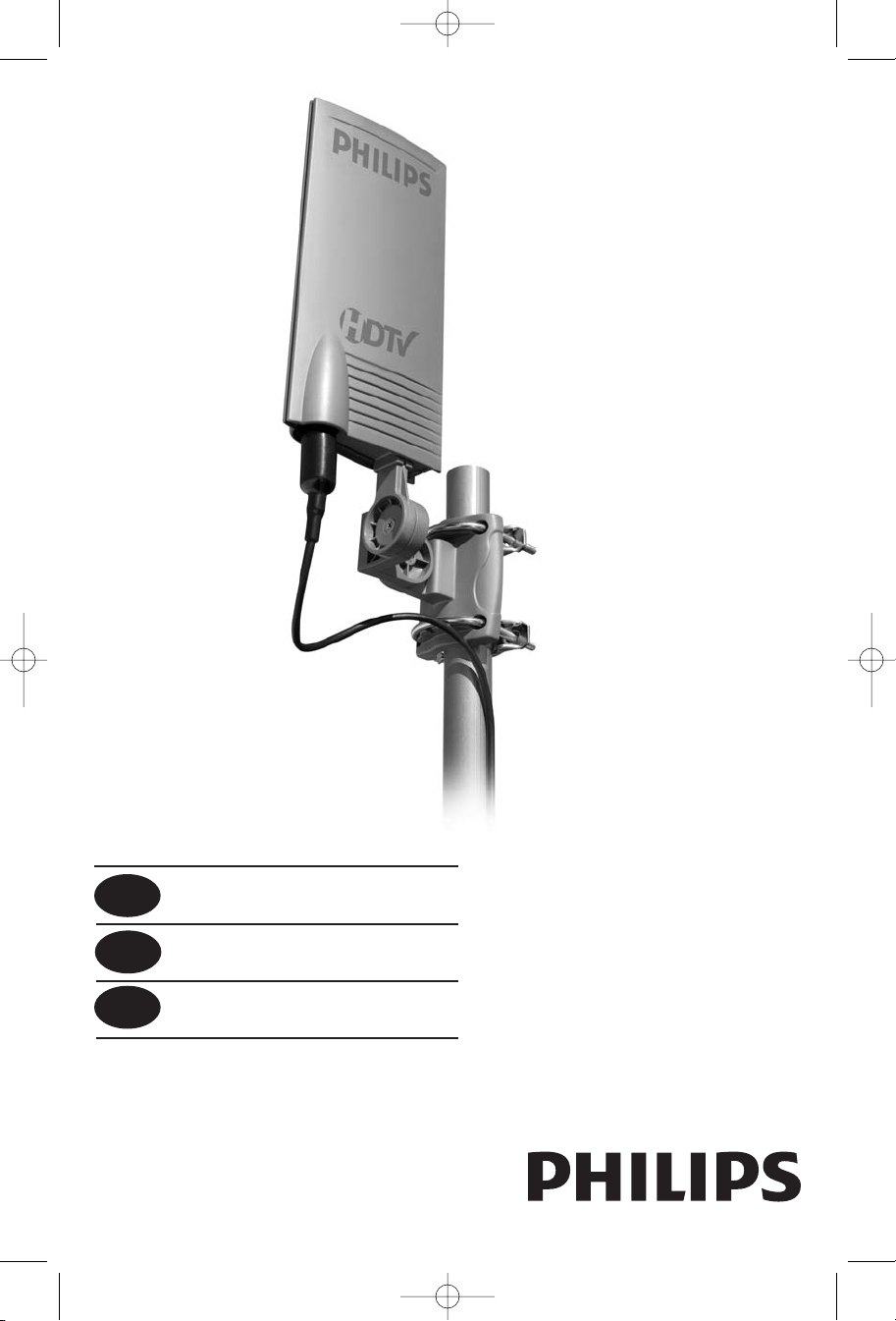
SDV2940/27
EN User manual 3
ES Manual de utilizador 9
FR Manuel d’utilisation 16
1
Page 2

SDV2940_27_manualV3.qxd 5/5/08 4:01 PM Page 2
EN
Contents
3 Safety Instructions
4 Important Information
5 Parts Included
5 Mounting Instructions
7 Connecting to Your TV
8 Warranty
8 Technical Support
Philips produces products of the highest quality. If you are having
technical problems, please call our accessory support help line at
919-573-7854 before returning the product to the store. (please see
page 7 of this instruction manual for details “Before You Start”).
2
Page 3

POWER SERVICE
GROUNDING ELECTRODE
SYSTEM (NEC ART250, PART H)
G
ROUNDING
CONDUCTORS
(NEC SECTION
810-21)
E
LECTRIC
SERVICE
E
QUIPMENT
G
ROUND CLAMPS
GROUND CLAMP
A
NTENNA
DISCHARGE UNIT*
(
NEC SECTION
810-20)
ANTENNA
LEAD-IN WIRE
SDV2940_27_manualV3.qxd 5/5/08 4:01 PM Page 3
Safety Instructions
Example of Antenna Gro
NEC – National Electrical Code
*
Antenna Discharge Unit is not required
if lead in conductors are enclosed in a
continuous metallic shield that is
permanently and effectively grounded.
unding as per
EN
Philips SDV2940
Indoor/Outdoor UHF/VHF Television antenna
Antenna grounding
If an outside antenna is connected to the receiver, make sure the
antenna system is grounded so as to provide protection against voltage surges and built up of static charges. Section 810 of the National
Electrical Code,ANSI/NFPA No. 70-1984, provides information with
respect to proper grounding of the mast and supporting structure,
grounding of the lead-in wire to an antenna discharge unit, size of
grounding connectors, location of antenna discharge-unit, connection to grounding electrodes, and requirements for the grounding
electrode. See DIAGRAM TO LEFT.
Important Safety Notes
If you do not feel comfortable or competent to install this antenna
we recommend that you seek the assistance of a qualified
professional antenna installer.
Read the instructions for this device thoroughly before
attempting installation.
IMPORTANT
READ
BEFORE
INSTALLATION
The installation or dismantling of any antenna near power lines is
dangerous. Each year hundreds of people are killed or injured while
attempting to install or service antennas. For your safety and proper
antenna installation, read and follow all safety precautions.
Outdoor antennas and lead-in conductors from antenna to a building should not cross over open conductors of electric light or power
circuits.They should be kept away from all circuits to avoid the possibility of accidental contact.
Each conductor of a lead-in from an outdoor antenna should be connected with an antenna discharge unit. Antenna discharge units (or
Lightning Arrestors) should be located outside the building between
and as near as prac-
the point of entrance or the lead-in and the
TV,
tical to the entrance of conductors to the building.
Choose an installation site for safety as well as performance.
er lines, cable lines and telephone lines look alike.
All electric po
w
To be safe, assume ANY overhead line can kill you.
Do not place an antenna where it could potentially fall on to,or blow
into a power line. If in doubt call your electric provider. Let them
review your site.
Outdoor antennas should be gr
Local codes ma
.
lighting ar
ound wir
gr
esting de
r
vice
.
e
ounded with an a
y. Use 8 AWG or larger
ppl
y a
pproved
3
Page 4

SDV2940_27_manualV3.qxd 5/5/08 4:01 PM Page 4
EN
Safety Instructions
IMPORTANT
BEFORE
INSTALLATION
READ
Height or other restrictions on antennas may apply to
your installation depending on your proximity to an airport,
or local ordinances.
Take the time to plan your installation procedure. Do all assembly
work on the antenna on the ground. Raise the completed antenna
after assembly.
Do NOT work on a wet, snowy or windy day or if a thunderstorm
is approaching. Do NOT use a metal ladder.
If the antenna assembly starts to fall, get away from it and let it fall.
Remember that the antenna mast and cable are all excellent conductors of electrical current.
Do NOT install the antenna by yourself. Be sure that there are two
other people available for help.
If any part of the antenna should come in contact with a power line
. . . DON'T TOUCH IT OR TRY TO REMOVE IT YOURSELF. Call
your local power company immediately.They will remove it.
Should an electrical accident occur . . . DON'T TOUCH THE
PERSON IN CONTACT WITH THE POWER LINE,or you too can
become electrocuted. Instead, use a DRY board, stick, or rope to
push or pull the victim away from the power lines and antenna.Once
clear, check the victim. If he has stopped breathing, immediately
administer cardiopulmonary resuscitation (CPR) and stay with him.
Have someone else call for medical help.
Install wire antennas high enough that they will not be "walked into"
by people.
Do not install antenna wire(s) over or under utility lines.
Important Information
Important installation inf
The SDV2940 uses a power injection module to power the
antenna amplifier.
It is essential for proper operation of this antenna system that
the amplifier be connected betw
such as splitters, matching transformers, networks, etc.
SEE DIAGRAM TO LEFT.
ding this impor
egar
Disr
power injector or improper operation / poor performance.
4
tant notice may result in damaging the
ormation
een the antenna and any devices
Page 5

SDV2940_27_manualV3.qxd 5/5/08 4:01 PM Page 5
Parts Included
1. SDV2940 Antenna. . . . . . . . . . . . . . . . . . . . . . 1
2. Power supply 120V to 6VDC . . . . . . . . . . . . 1
3. Wall / Mast Bracket. . . . . . . . . . . . . . . . . . . . 1
4. Nuts . . . . . . . . . . . . . . . . . . . . . . . . . . . . . . . . 2
5. U-Bolts . . . . . . . . . . . . . . . . . . . . . . . . . . . . . . 2
6. Mast clamps . . . . . . . . . . . . . . . . . . . . . . . . . . 2
7. Nuts with lock washers . . . . . . . . . . . . . . . . . 4
8. L-Bracket. . . . . . . . . . . . . . . . . . . . . . . . . . . . . 1
9. 2" Wood Screws. . . . . . . . . . . . . . . . . . . . . . . 4
10. 20' coax cable with connectors. . . . . . . . . . . 1
11. Weather Boot. . . . . . . . . . . . . . . . . . . . . . . . . 1
12. Power Injector . . . . . . . . . . . . . . . . . . . . . . . . 1
13. Plastic Anchors . . . . . . . . . . . . . . . . . . . . . . . . 4
Mounting Instructions
Determining signal strength
Before Installation determine the best location for optimum
reception. It is important for the antenna to have an unobstructed
path to the transmitter.To determine the transmitter(s) location you
can consult the website http://www.antennaweb.org.For best results
the antenna should be facing the transmitter location.
EN
Wall Mount
For indoor wall mount installation:
NOTE: Do all antenna assembly work on the ground before
installing on a wall or an antenna mast.
1. Attach main body to the L – bracket as shown, using cross
fig.1
fig.2
head screw note the orientation of the bracket.Do not fully
tighten the screw to allow for later adjustment (fig. 1).
2. Using the Wall/Mast bracket as a guide, mark position for the
four 2” wood screws.If possible locate a stud to screw into.
If a stud is not available, use appropriate wall anchors (not
included, available at any hardware store) (fig. 2).
5
Page 6

SDV2940_27_manualV3.qxd 5/5/08 4:01 PM Page 6
EN
Mounting Instructions
3. Attach the main body and L-bracket to wall / mast mounting
bracket using cross head screw (fig. 3) note the orientation of
the bracket. ) Do not fully tighten this screw to allow for
later adjustment (fig. 3).
4. Tighten all screws and nuts to firmly affix the antenna
to the wall.
5. Attach the cable to the F connector on the underside of the
fig.3
fig.4
unit and weather protection boot over the connection.
See next steps under – Connections to your TV
For outdoor mast mount installation:
NOTE: Do all antenna assembly work on the ground. Raise the
completed antenna after assembly.
1. Insert U-Bolts into the holes of the wall/mast bracket (fig. 4).
2. Slide the mast clamps onto the U-Bolts (fig. 4).
3. Attach the 4 nuts with lock washers to the U-Bolts - do not
tighten fully (fig. 4).
4. Slide the assembly on to the mast. Do not tighten fully, just
snug enough for the assembly to stay in place (fig.5).
5. Attach the L-Bracket to the wall / mast bracket using cross
head screw and nut, Note the orientation of the bracket.
Fully tighten this screw.
6. Attach the main body of the antenna to L bracket vertically.
7. Tighten all screws and nuts to firmly affix the antenna
fig.5
to the mast.
8. Adjustment of the antenna direction will be done by rotating
the mast in its mount.
9. Attach the cable to the ‘F’ connector on the underside of the
unit and weather protection boot over the connection (fig.6).
fig.6
6
Page 7

SDV2940_27_manualV3.qxd 5/5/08 4:01 PM Page 7
Connecting to Your TV
Before
You
Start
For this antenna to work properly, you must access the menu
on the television you are connecting this antenna to (consult
your television owner’s manual) then set it to receive the
signal from an ANTENNA instead of CABLE or SATELLITE.
Connections to your TV
fig.7
As previously noted the amplifier (Power Injector + Power
supply) must be placed in-line between the antenna and before
any splitter or additional devices.
1. Connect the coaxial cable from the antenna to the
F connector labeled ANT on the Power Injector.
2. Connect Power Injector to the antenna input on your TV,
Splitter and /or any other device.
3. Connect the Power Supply DC plug to the Power Injector
then plug the power supply adapter into a 110/120 Volt
AC receptacle.
Safety Note - The power injector and power supply is for indoor
use only!
EN
Alternate connections
1. If your TV has separate inputs for UHF and VHF you will
need to purchase a signal splitter that will separate the two
different signals.
2. If your TV has only two screw type antenna inputs you will
need to purchase a 75 Ohm to 300 Ohm transformer.
A note about coaxial cable – Your SDV2940 includes a 20 foot
roll of RG-59 coaxial cable. If you should find that this is not
adequate for your needs we recommend for best possible signal
integrity that you do not extend this cable.A better choice is to
replace the cable with either RG-6 or RG-6 Quad Shield cable.
Both of these cables ar
longer cable runs.This will ensur
erall performance.
v
o
e designed for minimal signal loss over
e the best possible picture and
7
Page 8
SDV2940_27_manualV3.qxd 5/5/08 4:01 PM Page 8
EN
Warranty
Limited One-Year Warranty
Philips warrants that this product shall be free from defects in material, workmanship and assembly, under normal use, in accordance
with the specifications and warnings, for one year from the date of
your purchase of this product.This warranty extends only to the
original purchaser of the product,and is not transferable.To exercise
your rights under this warranty, you must provide proof of purchase
in the form of an original sales receipt that shows the product name
and the date of purchase. For customer support or to obtain warranty service, please call 919-573-7854. THERE ARE NO OTHER
EXPRESS OR IMPLIED WARRANTIES. Philips’ liability is limited to
repair or, at its sole option, replacement of the product. Incidental,
special and consequential damages are disclaimed where permitted
by law.This warranty gives you specific legal rights.You may also have
other rights that vary from state to state.
Technical Support
For Technical support send an email with the model number
of the product and a detailed description of your problem to:
Email: accessorysupport@philips.com
Quality assured in USA
Printed in China
8
Page 9

SDV2940_27_manualV3.qxd 5/5/08 4:01 PM Page 9
Contenido
10 Instrucciones de seguridadr
11 Información importante
12 Partes incluidas
13 Armado y montaje de la antena
14 Conexión de su TV
15 Garantía limitada
15 Asistencia Técnica:
Philips fabrica productos de la mejor calidad. Si tiene algún problema
técnico, llame a nuestra línea de ayuda de asistencia para accesorios
al 919-573-7854 antes de devolver el producto al establecimiento.
(Consulte la página 14 de este manual de instrucciones para obtener
información "Antes de comenzar").
ES
9
Page 10

SISTEMA DE ELECTRODOS DE PUESTA
A TIERRA DEL SERVICIO DE ENERGÍA
ELÉCTRICA. (NEC ART 250, PART H)
CONDUCTORES DE
P
UESTA A TIERRA
(NEC SECTION 810-21)
E
QUIPO DE
SERVICIO
E
LÉCTRICO
GRAPAS DE PUESTA A TIERRA
GRAPA DE PUESTA A TIERRA
U
NIDAD DE
D
ESCARGA DE ANTENA*
(
NEC SECTION 810-20)
C
ABLE DE BAJADA
DE ANTENA
SDV2940_27_manualV3.qxd 5/5/08 4:01 PM Page 10
ES
Instrucciones de seguridad
Ejemplo de conexión a
tierra de una antena conforme al Código nacional
de electricidad (NEC)
*La unidad de descarga de
antena no es necesaria si
los conductores de derivación
se encuentran dentro de
una cobertura metálica
continua que está conectada
a tierra correctamente en
forma permanente.
Antena de televisión Philips SDV2940
Interior / Exterior UHF / VHF
Conexión a tierra de la antena
Si el receptor está conectado a una antena externa, la antena debe tener
una conexión a tierra para evitar sobretensiones y acumulación de cargas
estáticas. El artículo 810 del Código nacional de electricidad, ANSI/NFPA
Nº 70-1984, brinda información acerca de la conexión a tierra adecuada
del poste y del soporte, la conexión a tierra del cable de bajada hacia la
unidad de descarga de la antena, el tamaño de los conectores a tierra, la
ubicación de la unidad de descarga y la conexión a tierra de los electrodos
y sus requisitos. Véase el DIAGRAMA DE LA IZQUIERDA.
Notas importantes de seguridad
Si no se siente cómodo para instalar esta antena o siente que no
eres capacitado para hacerlo, le recomendamos que busque ayuda de un
colocador de antenas profesional calificado.
Lea bien las instrucciones correspondientes a este dispositivo antes de
intentar hacer la instalación.
La instalación o desinstalación de una antena cerca de las líneas de energía
es peligroso. Cada año cientos de personas mueren o resultan heridas
mientras intentan instalar o hacer el mantenimiento de antenas. Por su
seguridad y para que la antena quede instalada adecuadamente,lea y cumpla
todas las precauciones de seguridad.
Las antenas exteriores y los conductores de bajada que conectan la antena
con el edificio no deben pasar sobre conductores abiertos de circuitos de
luces u otros tipos de circuitos eléctricos.Deben estar alejadas de todo tipo
de circuitos para evitar contactos accidentales.
IMPORTANTE
LEER ANTES DE
INSTALAR
10
Cada conductor de bajada de una antena exterior debe conectarse con una
unidad de descarga. Las unidades de descarga de antena (o pararrayos)
deben ubicarse fuera del edificio entre el punto de entrada o de bajada y el
televisor,y cerca de la entrada de los conductores al edificio.
Elija un lugar para la instalación teniendo en cuenta la seguridad
y el r
endimiento
.
Todas las líneas de energía eléctrica, líneas de cable y telefónicas parecen
iguales. Para estar seguro,asuma que TODO cable aéreo puede matarlo.
No coloque una antena donde pueda caer sobre los cables de energía o
golpearlos. Si tiene dudas, llame la empresa de energía eléctrica. Permítales
revisar el lugar.
Las antenas exteriores deben estar colocadas con un dispositivo luminoso
distintivo aprobado. Pueden aplicarse los códigos locales. Use 8 AWG o
un cable de tier
ciones para antenas pueden ser a
ra más grande. Las restricciones sobre altura y otras restric-
plicables a su instalación dependiendo de
Page 11

SDV2940_27_manualV3.qxd 5/5/08 4:01 PM Page 11
Instrucciones de seguridad
IMPORTANTE
LEER ANTES DE
INSTALAR
ES
su proximidad a un aeropuerto,o según lo dispongan las ordenanzas locales.
Tómese su tiempo para planear el procedimiento de instalación.Realice
todo el trabajo de ensamblaje de la antena en el suelo. Levante la antena
completa luego del ensamblaje.
NO trabaje en días con humedad, nieve o viento ni si se aproxima una
tormenta. NO use una escalera de metal.
Si el ensamblaje de la antena comienza a caer, aléjese de él y déjelo caer.
Recuerde que la torre de la antena y el cable son excelentes
conductores de corriente eléctrica.
NO instale la antena solo. Asegúrese de que haya dos personas
disponibles para ayudarle.
Si alguna parte de la antena entra en contacto con una línea de
energía…NO LA TOQUE NI INTENTE QUITARLA USTED MISMO.
Llame a la empresa local de suministro de energía inmediatamente. Ellos
la quitarán.
Si ocurre un accidente con la electricidad. . . NO TOQUE A LA
PERSONA QUE ESTÁ EN CONTACTO CON LA LÍNEA DE ENERGÍA
o usted también quedará electrocutado.En lugar de ello, use una madera,
un palo o cuerda SECOS para empujar o jalar a la víctima y separarla de
las líneas de energía y la antena. Una vez que haya
separado a la víctima, revísela. Si ha dejado de respirar, inmediatamente
practique la resucitación cardio-pulmonar y quédese junto a ella.Pídale a
otra persona que llame a la asistencia médica.
Instale las antenas de cable a una altura suficiente para que la gente no “tropiece” con ellas.
No instale cables de antena por encima o por debajo de cables de
servicios públicos.
Información importante
Información importante sobre la instalación
La SDV2940 utiliza un pequeño amplificador externo para
talecer la señal de entrada de la antena.
or
f
Es imprescindible para el correcto funcionamiento de este sistema
de antena, que el amplificador esté conectado entre la antena y otros
dispositivos como divisores, transformadores de congruencia, redes,
etc.
No prestar atención a esta importante indicación puede resultar en
daños al inyector de potencia o en un funcionamiento
inapropiado/bajo rendimiento.
11
Page 12

SDV2940_27_manualV3.qxd 5/5/08 4:01 PM Page 12
ES
Piezas incluidas:
1. Antena SDV2940 . . . . . . . . . . . . . . . . . . . . . . . .1
2. Alimentación 12V a 6VDC . . . . . . . . . . . . . . .1
3. Soporte de pared/mástil . . . . . . . . . . . . . . . . . .1
4. Tuercas . . . . . . . . . . . . . . . . . . . . . . . . . . . . . . . .2
5. Pernos en U . . . . . . . . . . . . . . . . . . . . . . . . . . .2
6. Abrazaderas de mástil . . . . . . . . . . . . . . . . . . . .2
7. Tuercas con arandelas de cerrojo . . . . . . . . . .4
8. Soporte en L . . . . . . . . . . . . . . . . . . . . . . . . . . .1
9. Tornillos para Madera de 2˝ . . . . . . . . . . . . . . .4
10. Cable coaxial de 20 ft. . . . . . . . . . . . . . . . . . . . .1
11. Capuchón protector . . . . . . . . . . . . . . . . . . . . .1
12. Inyector de potencia . . . . . . . . . . . . . . . . . . . . .1
13. Sujetadores plásticos . . . . . . . . . . . . . . . . . . . .4
Armado y montaje de la antena
Antes de la instalación determine el mejor lugar para una
recepción óptima. Es importante que la antena tenga una ruta
sin obstáculos hacia el transmisor. Para determinar la ubicación
del transmisor puede consultar la página Web
http://www.antennaweb.org. Para obtener los mejores resultados
la antena debe estar enfocada hacia la ubicación del transmisor
como se muestra abajo.
12
Instrucciones generales para el armado y montaje de la antena.
Para instalación interior en pared:
NOTA: Realice todas las tareas de ensamblado de la antena
en el piso antes de instalar la antena a la pared o el mástil
fig.1
de antena.
1. Fijar el cuerpo principal al sopor
utilizando tornillo con cabeza de cruz.Tenga en cuenta la
orientación del soporte. No apretar totalmente el tornillo
para permitir un ajuste posterior (fig. 1).
2. Utilizando el soporte pared/mástil como una guía, marcar la
posición de los cuatro tornillos de 2” para madera. Si es
posible, localice un montante para atornillarlo a el. Si no hay un
montante disponible, utilice los sujetadores de pared apropiados (no incluidos, disponibles en cualquier ferretería) (fig. 2).
fig.2
te en L según se indica,
Page 13

SDV2940_27_manualV3.qxd 5/5/08 4:01 PM Page 13
Armado y montaje de la antena
3. Fijar el cuerpo principal y soporte en L al soporte de
pared/mástil, utilizando tornillo con cabeza de cruz (fig. 3) vea
la orientación del soporte. No apretar totalmente este tornillo
para permitir un ajuste posterior.
4. Apretar todos los tornillos y tuercas para ajustar la antena
firmemente a la pared.
5. Adosar el cable al conector F en la parte inferior de la unidad
fig.3
y coloque el capuchón protector sobre la conexión.
Vea los pasos siguientes bajo - Conexiones a su TV
Instalación exterior en mástil
NOTA: Realice todas las tareas de ensamblado de la antena en
el piso. Levante a antena completa una vez ensamblada.
1. Insertar los pernos en U en los orificios del soporte de
pared/mástil (fig. 4).
2. Deslice las abrazaderas de mástil sobre los pernos en U
(fig. 4).
ES
3. Colocar las 4 tuercas con arandelas de cerrojo a los pernos
fig.4
fig.5
en U – no apretar totalmente (fig. 4).
4. Deslizar el ensamblaje sobre el mástil. No ajustar totalment,
solo lo suficiente para que el ensamblaje permanezca en su
sitio (fig. 5).
5. Fijar el soporte en L al soporte de pared/mástil, utilizando
tornillo con cabeza de cruz y tuerca vea la orientación del
soporte. Apretar completamente este tornillo.
6. Fijar el cuerpo principal de la antena al sopor
L verticalmente.
7. Apretar todos los tornillos y tuercas para ajustar la antena
firmemente al mástil.
8. El ajuste de la dirección de la antena se realiza rotando el
mástil dentro de su soporte.
te en
13
Page 14

SDV2940_27_manualV3.qxd 5/5/08 4:01 PM Page 14
ES
fig.6
Armado y montaje de la antena
9. Colocar el cable al conector F en la parte inferior de la
unidad y coloque el capuchón protector sobre la conexión
(fig. 6).
Vea los pasos siguientes bajo - Conexiones a su TV
Conexiones a su TV
Antes
de
comenzar
Para que la antena funcione correctamente, debe acceder al
menú del televisor al que esté conectada (consulte el manual de
instrucciones del televisor) y, luego, configúrelo para que reciba la
señal desde una ANTENA en lugar de un CABLE o SATÉLITE.
Conexiones a su TV
fig.7
Según se indicara previamente el amplificador (inyector de
potencia + alimentación) deben estar colocados en línea entre la
antena y antes de cualquier divisor o dispositivo adicional.
14
1. Conectar el cable coaxial de la antena al conector F rotulado
como ANT en el inyector de potencia.
2. Conectar el inyector de potencia a la entrada de antena en su
TV, divisor y/o cualquier otro dispositivo.
3. Conectar el conector de alimentación de corriente DC al
inyector de potencia y luego conectar el adaptador de corriente eléctrica a un enchufe 110/120 voltios AC.
Indicación de seguridad: El inyector de potencia y la alimentación
de corriente son de uso interior únicamente!
Conexiones alternativas
TV cuenta con entradas independientes para UHF y VHF
Si su
1.
usted deberá comprar un divisor de señal que separ
señales diferentes.
2. Si su TV cuenta únicamente con las entradas de antena del
tipo de dos tornillos deberá comprar un transf
ohmios a 300 ohmios.
Una nota sobre el cable coaxial: Su SDV2940 incluye un rollo de
20 pies de cable coaxial RG-59.
medida no se adecua a sus necesidades,
lograr la mejor integridad de señal posible, no añadir este cable.
Si usted considera que esta
ecomendamos, para
r
e las dos
ormador de 75
Page 15

SDV2940_27_manualV3.qxd 5/5/08 4:01 PM Page 15
Conexiones a su TV
Una mejor opción es sustituir el cable ya sea con RG-6 o
RG-6 con blindaje cuádruple.Ambos cables han sido diseñados
para una pérdida de señal mínima en recorridos de cable
más extensos. Esto asegurará la mejor imagen y rendimiento
general posibles.
Garantía
Garantía limitada por un año
Philips garantiza que este producto carece de defectos de material,
manufactura o armado,bajo uso normal y de acuerdo con las especificaciones y advertencias, por el plazo de un año a partir de la fecha de
compra de este producto. Esta garantía cubre únicamente al comprador original del producto y no es transferible.Para ejercer sus derechos bajo esta garantía, debe proporcionar una prueba de compra
mediante una factura original que muestre el nombre del producto y la
fecha de compra. Por atención al cliente o para obtener servicio de
garantía, sírvase llamar al 919-573-7854. NO EXISTEN OTRAS
GARANTÍAS IMPLÍCITAS O EXPLÍCITAS. Las obligaciones de Philips
se limitan a la reparación o,a su sola opción, al reemplazo del producto.No se aceptan reclamos por daños incidentales, especiales e indirectos, de acuerdo a lo permitido por la ley.Esta garantía le otorga a usted
derechos legales específicos. Usted también tener otros derechos que
pueden variar de estado a estado.
ES
Asistencia Técnica
Correo electrónico:
accessorysupport@philips.com
Calidad comprobada en los EE.UU.
Imprimido en China
15
Page 16

SDV2940_27_manualV3.qxd 5/5/08 4:01 PM Page 16
FR
Manuel d’utilisation
17 Consignes de sécurité
19 Renseignements importants
19 Pièces fournies
19 Instructions de montage
21 Connexions à votre téléviseur
22 Garantie
23 Soutien technique
Philips fabrique des produits de la plus haute qualité. Si vous avez
des problèmes techniques, avant de renvoyer le produit au détaillant,
appelez notre service d’assistance pour les accessoires au
919-573-7854. (Pour plus de détails, reportez-vous à la section
« Avant de commencer » à la page 21).
1616
Page 17

S
ISTEMA DE ELECTRODOS DE PUESTA
A TIERRA DEL SERVICIO DE ENERGÍA
ELÉCTRICA. (NEC ART 250, PART H)
CONDUCTORES DE
P
UESTA A TIERRA
(NEC SECTION 810-21)
E
QUIPO DE
SERVICIO
E
LÉCTRICO
GRAPAS DE PUESTA A TIERRA
GRAPA DE PUESTA A TIERRA
U
NIDAD DE
DESCARGA DE ANTENA*
(
NEC SECTION 810-20)
C
ABLE DE BAJADA
DE ANTENA
SDV2940_27_manualV3.qxd 5/5/08 4:01 PM Page 17
Consignes de sécurité
Exemple de mise à la
terre d'une antenne
conformément au
Code national de
l'électricité
* Le parafoudre n'est pas
nécessaire si les conducteurs
sont dotés d'un revêtement
métallique continu qui est mis
à la terre en permanence.
FR
Philips SDV2940
Antenne de télévision UHF/VHF
intérieure ou extérieure
Mise à la terre de l’antenne
Si une antenne extérieure est reliée au récepteur, assurez-vous qu'elle est
mise à la terre afin de protéger celui-ci contre les surtensions et l'accumulation d'électricité statique.
La section 810 du Code national de l'électricité,ANSI/NFPA nº 70-1984,
fournit des informations sur la mise à la terre d'un mât d'antenne et de sa
structure portante, la mise à la terre du câble d'antenne vers un
parafoudre, le calibre des connecteurs de mise à la terre, l'emplacement
du parafoudre, le branchement des électrodes de mise à la terre et les
spécifications des électrodes. Reportez-vous au diagramme de gauche.
Remarques importantes en matière de sécurité
Si vous n’êtes pas à l’aise ou si vous avez des doutes concernant l’installation de l’antenne, nous vous recommandons de faire appel aux services
d’un installateur d’antennes qualifié.
Lisez soigneusement les instructions avant de procéder à l’installation.
Il est très dangereux d’installer ou de démonter une antenne située près
de lignes électriques.Chaque année, des centaines de personnes meurent
ou sont gravement blessées en tentant d’installer ou de réparer des
antennes.Afin d’assurer votre sécurité et de garantir que l'antenne sera
adéquatement installée, lisez et respectez toutes les mesures de sécurité.
IMPORTANT:
LIRE AVANT DE
PROCÉDER À
L’INSTALLATION
Les antennes extérieures et leurs câbles ne doivent pas croiser des
conducteurs électriques dénudés dans un bâtiment. Ils doivent être
éloignés de tous les circuits électriques afin d’éviter tout risque de
contact accidentel.
Chaque conducteur d'un câble d’antenne extérieure doit être relié à un
parafoudre. Le parafoudre d'antenne doit être installé à l’extérieur, entre
le câble d'antenne et le téléviseur, le plus près possible de l'endroit où le
câble pénètre dans l’immeuble.
Choisissez un lieu d’installation à la fois sécuritaire et qui assurera la
meilleure réception possible.
Toutes les lignes électriques, les câbles et les lignes téléphoniques se
ressemblent.
Pour des raisons de sécurité,faites comme siTOUTES les lignes aériennes
représentaient un risque d’accident mortel.
17
Page 18

SDV2940_27_manualV3.qxd 5/5/08 4:01 PM Page 18
FR
Consignes de sécurité
Ne placez pas l’antenne à un endroit présentant des risques de contact
avec une ligne électrique.Si vous avez des doutes,n’hésitez pas à communiquer avec votre fournisseur d’électricité.Il examinera votre installation.
Les antennes extérieures devraient être mises à la terre en utilisant
un parafoudre approuvé.Certains codes municipaux peuvent s’appliquer.
Utilisez un conducteur de mise à la terre de calibre 8 ou plus gros.
La hauteur ou d’autres restrictions relatives aux antennes peuvent s’ap-
pliquer à votre installation selon la distance à laquelle vous vous situez
d’un aéroport ou des ordonnances municipales.
Prenez le temps de bien planifier l’installation.Exécutez au sol tout le tra-
vail d’assemblage de l’antenne. Soulevez l’antenne une fois l’assemblage
terminé.
N’effectuez PAS le travail pendant la pluie, la neige, des grands vents ou
alors qu’il y a avertissement de tempête. N’utilisez PAS d’échelle
métallique.
Si l’antenne semble sur le point de tomber, éloignez-vous et laissez-la
tomber.N’oubliez pas que le mât et le câble coaxial sont d’excellents conducteurs d’électricité.
Ne procédez JAMAIS seul à l’installation de l’antenne.Assurez-vous que
lors de l’installation, au moins deux autres personnes se trouvent sur
place.
18
Si l’une des parties de l’antenne devait entrer en contact avec une ligne
électrique. . . N’Y TOUCHEZ PAS ET N’ESSAYEZ PAS DE L’ENLEVER.
Communiquez immédiatement avec votre fournisseur d’électricité qui
s'en occupera à votre place.
En cas d’accident électrique, . .. NE TOUCHEZ PAS À LA PERSONNE
EN CONTACT AVEC LA LIGNE ÉLECTRIQUE,sinon vous risquez aussi
d’être électrocuté. Utilisez plutôt un panneau de bois, une corde ou un
bâton,qui sont SECS, pour éloigner la victime des lignes électriques et de
l’antenne. Lorsque cela est fait,examinez la victime. Si elle ne respire plus,
procédez immédiatement à une réanimation cardio-respiratoire et restez
à ses côtés. Demandez à quelqu’un d’a
Installez les fils d’antenne à une hauteur adéquate, c’est-à-dire de manière
à éviter que les gens marchent dessus.
N’installez pas les fils d’antenne sur ou sous des câbles de service public.
ppeler une ambulance.
Page 19

SDV2940_27_manualV3.qxd 5/5/08 4:01 PM Page 19
Renseignements importants
Renseignements importants concernant l’installation
L’antenne SDV2940 utilise un injecteur de puissance pour alimenter
son amplificateur.
Pour assurer le bon fonctionnement de ce système d’antenne, il est
essentiel que l’amplificateur soit connecté entre l’antenne et tous les dispositifs comme des diviseurs, des amplificateurs supplémentaires, des
transformateurs d’adaptation, des réseaux, etc. CONSULTER LE DIAGRAMME DE GAUCHE.
Le non respect de cette directive pourrait endommager l’injecteur de
puissance ou empêcher le bon fonctionnement de l’antenne.
Pièces fournies :
1. Antenne SDV2940 . . . . . . . . . . . . . . . . . . . . . . . . . .1
2. Source d’alimentation 120 V c.a. à 6 V c. c. . . . . . .1
3. Support au mur ou au mât . . . . . . . . . . . . . . . . . . .1
4. Écrous . . . . . . . . . . . . . . . . . . . . . . . . . . . . . . . . . . .2
5. Boulons en U . . . . . . . . . . . . . . . . . . . . . . . . . . . . . .2
6. Colliers de mât . . . . . . . . . . . . . . . . . . . . . . . . . . . .2
7. Écrous avec rondelles frein . . . . . . . . . . . . . . . . . . .4
8. Attache en L . . . . . . . . . . . . . . . . . . . . . . . . . . . . . .1
9. Vis à bois de 5 cm (2 po) . . . . . . . . . . . . . . . . . . . .4
10. Câble coaxial de 6 m (20 pi) avec connecteurs . . .1
11. Gaine d’étanchéité . . . . . . . . . . . . . . . . . . . . . . . . . .1
12. Injecteur de puissance . . . . . . . . . . . . . . . . . . . . . . .1
13. Ancrages en plastique . . . . . . . . . . . . . . . . . . . . . . .4
FR
Instructions de montage
Déterminer la puissance du signal
Avant l’installation, déterminez l’emplacement idéal pour la meilleure
réception. Il est important qu’il n’y ait pas d’obstruction entre l’émetteur
our déterminer l’emplacement des émetteurs,
P
et l’antenne
site
tenne devrait faire face à l’emplacement des émetteurs.
.
eb http://www.antennaweb.org. Pour de meilleurs résultats, l’an-
W
consultez le
19
Page 20

SDV2940_27_manualV3.qxd 5/5/08 4:01 PM Page 20
FR
Instructions de montage
Pour une installation sur un mur intérieur :
REMARQUE : Effectuez tout le travail d’assemblage de l’antenne au sol
avant de l’installer sur un mur ou sur un mât.
1. Fixez le corps principal sur l’attache en L, tel que montré, en
utilisant la vis cruciforme et faites attention à l’orientation de
l’attache. Ne serrez pas complètement la vis pour pouvoir terminer l’ajustement par la suite (fig. 1).
fig.1
2. Utilisez le support sur le mur ou sur le mât comme point
de repère et marquez la position des quatre vis à bois de 5
cm (2 po). Si possible, trouvez un montant sur lequel vous les
visserez.
S’il n’y a pas de montant en cet endroit, utilisez des ancrages
muraux appropriés (non fournis, mais vous pouvez vous en
procurez dans une quincaillerie) (fig. 2).
3. Fixez le corps principal avec l’attache en L sur le support pour
le mur ou pour le mât en utilisant la vis cruciforme (fig. 3) et
fig.2
Support mural
faites attention à l’orientation de l’attache. Ne serrez pas complètement la vis pour pouvoir terminer l’ajustement par la
suite (fig. 3).
4. Serrez toutes les vis et les écrous pour fixer solidement l’antenne sur le mur.
20
5. Branchez le câble coaxial dans le connecteur F situé sous l’antenne, puis faites glisser la connexion dans la gaine d’étanchéité.
Reportez-vous aux instructions suivantes à la section :
Connexions à votre téléviseur
fig.3
Pour une installation sur un mât à l’extérieur :
REMARQUE : Effectuez tout le travail d’assemblage de l’antenne au sol.
ez l’antenne une fois l’assemblage terminé.
v
Soule
ez les boulons en U dans les trous du suppor
Insér
1.
ou sur le mât (fig.
2. Faites glisser les colliers du mât sur les boulons en U (fig. 4).
Fixez les 4 écrous avec les rondelles frein sur les boulons en U
3.
fig.4
en ne les serrant pas trop fort (fig. 4).
4).
t sur le mur
Page 21

SDV2940_27_manualV3.qxd 5/5/08 4:01 PM Page 21
Instructions de montage
4. Faites glisser l’assemblage sur le mât. Ne serrez pas trop, mais
juste assez pour que l’assemblage reste en place. (fig. 5).
5. Fixez l’attache en L au support sur le mur ou sur le mât en
utilisant la vis cruciforme et l’écrou et faites attention à l’orientation de l’attache. Serrez fermement cette vis.
6. Fixez le corps principal de l’antenne verticalement sur l’attache
fig.5
fig.6
en L.
7. Serrez toutes les vis et les écrous pour fixer solidement l’antenne au mât.
8. L’orientation de l’antenne sera ajustée par une rotation du mât
sur son socle.
9. Fixez le câble coaxial au connecteur F situé sous l’antenne, puis
faites glisser la connexion dans la gaine d’étanchéité (fig. 6).
Connexions à votre téléviseur
FR
Avant de
commencer
Pour que cette antenne fonctionne adéquatement, vous devez
sélectionner un signal d’entrée de l’ANTENNE plutôt que du CÂBLE
ou du SATELLITE au menu du téléviseur qui y est connecté
(consultez la documentation du téléviseur).
Connexions à votre téléviseur
Tel que mentionné précédemment, l’amplificateur (injecteur de puissance
+ bloc d’alimentation) doit être connecté en série entre l’antenne et le
fig.7
séparateur ou tout autr
1. Branchez le câble coaxial de l’antenne au connecteur F marqué
ANT » sur l’injecteur de puissance.
«
2. Connectez l’injecteur de puissance dans l’entrée d’antenne du
du séparateur ou de tout autre dispositif.
téléviseur
Branchez la minifiche du bloc d’alimentation de courant
3.
contin
bloc d’alimentation dans une prise électrique de 110/120 Vca.
Remar
mentation sont conçus pour êtr
,
u dans l’injecteur de puissance, puis branchez la fiche du
que de sécurité :
e dispositif.
l’injecteur de puissance et le bloc d’ali
e utilisés à l’intérieur uniquement.
-
21
Page 22

SDV2940_27_manualV3.qxd 5/5/08 4:01 PM Page 22
FR
Connexions à votre téléviseur
Autres méthodes de connexion
1. Si votre téléviseur comporte des entrées UHF et VHF séparées,
vous devrez acheter un diviseur pour séparer les deux signaux.
2. Si le téléviseur est uniquement doté d’une entrée d’antenne à 2
vis, vous devrez acheter un transformateur de 75 à 300 ohms.
Remarque à propos du câble coaxial : l’antenne SDV2950 comprend une
bobine de 6 m (20 pi) de câble coaxial RG-59. Si cela ne convient pas à
vos besoins, pour assurer une qualité de réception optimale, nous vous
recommandons de ne pas rallonger ce câble.Si ce câble n’est pas assez long,
il est préférable de le remplacer par du câble coaxial RG-6 ou RG-6
à quadruple blindage.Ces deux types de câble sont conçus pour minimiser
les pertes de signal sur de plus grandes longueurs de câble. Cela vous
procurera une meilleure qualité d’image et une performance globale plus
satisfaisante.
Garantie
Garantie limitée d’un an
Philips garantit que ce produit est dépourvu de défauts au niveau des
matériaux, de la main d’œuvre et du montage, moyennant des conditions
normales d’utilisation, conformément aux spécifications et aux avertissements, pour une durée d’un an à compter de la date à laquelle vous avez
acheté ce produit. Cette garantie est seulement accordée au propriétaire
d’origine du produit et n’est pas transférable. Pour vous prévaloir du service en vertu de cette garantie, vous devez fournir une preuve d’achat sous
la forme du ticket de caisse original indiquant le nom du produit et la date
d’achat. Pour un support clientèle ou pour obtenir un service de garantie,
veuillez appeler 919-573-7854.AUCUNE AUTRE GARANTIE, QU’ELLE
SOIT EXPRESSE OU TACITE, N’EST OFFERTE. La garantie de Philips est
limitée à la réparation ou, à sa seule discrétion, au remplacement du produit. Les dommages accessoires, spéciaux et indirects ne sont pas acceptés
dans les limites permises par la loi.
reconnus par la loi.Vous pouvez également disposer d’autres droits suivant
les états.
Cette garantie vous donne des droits
22
Page 23

SDV2940_27_manualV3.qxd 5/5/08 4:01 PM Page 23
Soutien technique
Pour obtenir du soutien technique, envoyez un courriel indiquant le
numéro de modèle du produit et une description détaillée du problème
à l’adresse suivante :
Courriel : accessorysupport@philips.com
Qualité assurée aux États-Unis
Imprimé en Chine
FR
23
Page 24

SDV2940_27_manualV3.qxd 5/5/08 4:01 PM Page 24
©2008 Koninklijke Philips Electronics N.V., All rights reserved
www.philips.com
 Loading...