

Page 1

OWNER’S
MANUAL
AND
SET-UP GUIDE
E
N
H
A
N
C
E
D
F
O
C
U
S
®
TELEVISION
IndustryStandards
™
ScanCard II™
Professional Color Television
SCAN 2 10/3/00 10:49 AM Page 1
Page 2
For Customer Use:
Enter below the Serial No. which is located on
the product. Retain this information for future reference.
Model No
Serial No.
ScanCard IITM, SmartCardTMTelevision, SmartLinkTMConnector and
SmartPlug
TM
Series are all registered trademarks of the Philips Consumer
Electronics Company.
Microsoft WINDOWS™and the WINDOWS™logo are registered trade-
marks of the Microsoft Corporation in the United States and/or other
countries.
MACINTOSH™is the registered trademark of Apple Computer.
t This “bolt of lightning” indicates uninsulated material
within your unit which may cause an electrical shock. For
the safety of everyone in your household, please do not
remove product covering.
s The “exclamation point” calls attention to features for
which you should read the enclosed literature closely to
prevent operating and maintenance problems.
WARNING: TO PREVENT FIRE OR SHOCK HAZARD,
DO NOT EXPOSE THIS EQUIPMENT TO RAIN OR
MOISTURE.
CAUTION: To prevent electric shock, match wide blade of
plug to wide slot, and fully insert.
ATTENTION: Pour éviter les chocs électrques, introduire
la lame la plus large de la fiche dams la borne correspondante de la prise et pousser jussssqu'au fond.
t
s
CAUTION
RISK OF ELECTRIC SHOCK
DO NOT OPEN
CAUTION: TO REDUCE THE RISK OF ELECTRIC SHOCK, DO NOT
REMOVE COVER (OR BACK). NO USER-SERVICEABLE PARTS
INSIDE. REFER SERVICING TO QUALIFIED SERVICE PERSONNEL.
KNOW THESE SAFETY SYMBOLS
3
2
TABLE OF CONTENTS
Getting Started
Warning/Precautions . . . . . . . . . . . . . . . . . . .2
Introduction . . . . . . . . . . . . . . . . . . . . . . . . .4
Features . . . . . . . . . . . . . . . . . . . . . . . . . . . .5
Unpacking and Assembly . . . . . . . . . . . . . . . . . . . .6-7
Installation . . . . . . . . . . . . . . . . . . . . . . . . . . . . . . .8-9
Input/Output Jacks . . . . . . . . . . . . . . . . . . . . . . . . . . .9
Hooking up the ScanCard ll Television
• Antenna TV Connections . . . . . . . . . .10-11
• Cable TV Connections . . . . . . . . . . . .12-13
• Audio/Video Input Connections . . . . . . . . . . .14-15
• S-Video Input Connections . . . . . . . . . . . . . . .16-17
• VGA Input Connections (PC, Macintosh) . . . .18-19
• RS 232 Input Connection . . . . . . . . . . . . . . . . . . .20
Basic Operations
• Basic Television Control Panel Operations . .21
• Basic Remote Control Operations . . . . . .22-23
On-Screen Menu Options
• On-Screen Menu and Picture Adjustments .24
• TV Picture Setup Menu . . . . . . . . . . . . . . .25
• Description of TV Picture Setup Options . . . . . . .25
• VGA Picture Setup Menu . . . . . . . . . . . . . . . . . . .26
• Description of VGA Picture Setup Options . . . . .27
• VGA Image Adjustments . . . . . . . . . . . . . . . . . . .28
• Description of VGA Image Adjustments . . . . . . .29
• Commercial Settings Menu . . . . . . . . . . . . . . . . .30
• Description of Commercial Settings . . . . . . . . . . .31
• Television Features . . . . . . . . . . . . . . . . . . . . . . .32
• Description of Television Features . . . . . . . . .32-34
Closed Captioning . . . . . . . . . . . . . . . . . . . . . . . . . .35
Zoom and Pan Feature . . . . . . . . . . . . . . . . . . . . . . .36
General Information
Index . . . . . . . . . . . . . . . . . . . . . . . . . . . . .37
Glossary . . . . . . . . . . . . . . . . . . . . . . . . . . .38
Warranty . . . . . . . . . . . . . . . . . . . . . . . . . .39
SCAN 2 10/3/00 10:49 AM Page 2
12
1
11
2
10
3
9
4
8
5
7
6
Page 3

5
FEATURES
• Scan Conversion of VGAinput is as follows, but not
limited to:
Mode Resolution Horiz. Vert.
VGA TEXT 720 x 400 31.5kHz 70Hz
VGA/MCGA 320 x 200 31.5kHz 70Hz
VGA 640 x 350 31.5kHz 70Hz
VGA 640 x 400 31.5kHz 70Hz
VGA 640 x 480 31.5kHz 60Hz
VGA/VESA 640 x 480 37.8kHz 72Hz
SVGA/VESA 800 x 600 35.2kHz 56Hz
SVGA/VESA 800 x 600 37.9kHz 60Hz
SVGA/VESA 800 x 600 48.1kHz 72Hz
XGA/VESA 1024 x 768 48.3kHz 60Hz
XGA/VESA 1024 x 768 56.4kHz 70Hz
XGA/VESA 1024 x 768 61.1kHz 75.8Hz
*Mac 13” 640 x 480 35 60Hz
*E-Mac 832 x 624 44.9 67Hz
*Mac 16” 832 x 624 49.7 75Hz
*Super Mac 1024 x 768 48 60Hz
*Mac 19” 1024 x 768 60.2 75Hz
* ScanCard II requires separate sync signals.
All Macintosh Computers have not been tested with this product
• VGA/SVGA Input with buffered Loop-thru Output.
• VGA/SVGA Audio Input
• S-VIDEO Video/Audio Inputs with Loop-thru
Outputs.
• AUX Video/Audio Inputs with Loop-thru
Outputs.
• Clone Port for limited applications.
• RS 232 Connecter allows interface of a computer
and the TV, giving control of the TV functions to the
computer.
• Independent TV picture controls (bright, picture)
for each mode of display (TV or VGA).
• Switchable Anti-Flicker vertical filter (ON or OFF).
• Adjustable horizontal and vertical positioning
of the VGA display.
• Adjustable horizontal and vertical scaling of
picture size. Including a Pan and Zoom option on the
remote.
• VGA/SVGA 2x Zoom Mode with Pan Capability.
• Audio/Video jack panel for direct connections
with VCRs (or other video accessories) for
quality TV picture and sound playback.
• MAC Adapter 50-75Hz flexible refresh rate.
4
ScanCard II provides a method of displaying VGA/SVGA,
composite video, S-Video, and various audio connections to
any of the Philips 19”, 25”, 27”, 32” or 36” SmartCard televisions. This allows the user more dynamic picture and
sound quality when using computers, video cameras,
VCRs, DVD Players, Laser Disc Players, CD-i Players,
Web Browsers, and Satellite Systems.
With use of a T374AH Setup Remote (see T374AH Remote
Control Instructions - part # IB7166E002 for complete
details), the installer can adjust the normal commercial tele-
vision functions (with the exception of the BRIGHTNESS
and PICTURE settings for VGA and NON-VGA display
modes). ScanCard II will store a separate set of BRIGHTNESS and PICTURE settings for these display modes. This
allows the display to be optimized for computer generated
graphics while retaining display settings that are pleasing
for off-air or accessory equipment viewing (VCR, DVD,
etc.).
With the ability to adjust the picture through horizontal and
vertical scaling, ScanCard II allows full use of your display
when using the most current computer software applications.
When tuned to the VGA channel, ScanCard II gives the
option of viewing the display twice as large with a 2x
ZOOM feature. This larger display can be “PANNED” left,
right, up, or down by pressing the remote’s CURSOR
keys.
This unique television module can easily be linked or
“daisy chained” to multiple monitors using the “loopthrough” jacks located on the rear jack panel of ScanCard
II. You can create a central control area with many monitoring stations, ideal for educational purposes.
Access to additional external inputs provided by ScanCard
II can be obtained simply by changing channels. Using the
channel UP/DOWN buttons to select the three channels
directly below the lowest broadcast channel, will allow the
use of AUX, S-VIDEO, and VGA inputs. These “channels”
can also be selected directly using the supplied remote.
This remote has dedicated buttons labeled SVID, VGA, and
AUX. Pressing any of these buttons will directly tune the
SmartCard TV to it’s respective channel (or input jack).
ScanCard II transforms any SmartCard television into the
ultimate display for computer graphics, TV broadcast programming, inter-active CD-Rom, DVD, Laser Disc Players
or any of today’s hi-tech entertainment devices.
INTRODUCTION
SCAN 2 10/3/00 10:49 AM Page 4
Page 4

7
Rear Cover in
Bubble Pack Bag
RF Plug, Nut and
Hex Head Screw
(In Poly Bag)
Cardboard Box
Jack Panel Board
(Packed in folded
cardboard and plastic)
ScanCard II
Circuit Board
(Packed in folded
cardboard and plastic)
ScanCard II
Circuit Board
Jack Panel Board
Hex Head Screw
RF Input Plug
ScanCard II Assembly Cover
RF Input Plug Retaining Nut
25 Pin Board
Connector
Unpacking
Assembly
6
S
CANCARD
II A
SSEMBLY
W
hen unpacking the ScanCard II compo-
nents from the box, be careful pulling the
items out. The box is packed with five separately packaged items; The ScanCard II Assembly
Cover, the ScanCard II Circuit Board, the
ScanCard II Jack Panel Board, the RF Input
Plug/Retaining Nut/Hex Head Screw, and the
Remote Control Unit. Unfold the Cardboard
holders to release the two Circuit Boards and
use the following instructions to assemble the
unit.
Line up the 25 pin connector on the
ScanCard II Circuit board with the 25 pin connector on the Jack Panel board. Carefully but
firmly, press the connectors together until the
pins are fully set into the designated connector.
Attach the RF Input Plug to the ScanCard II
Assembly Cover, and use the Retaining Nut to
secure it to the cover.
Using the Hex Head Screw supplied, secure
the Jack Panel board to the ScanCard II Cover.
Remember to be careful when pushing the
25 Pin connectors together. Try not to bend or
force the pins into place. If they will not slide in easily,
please disconnect the two boards and start over.
Do not over tighten the Hex Head Screw when securing
the Assembly to its cover. Over tightening can cause
stripping of the ScanCard II Assembly Cover.
SMART HELP
Remote Control
SCAN 2 10/3/00 10:49 AM Page 6
BEGIN
PHILIPS
ZOOM
STATUS
EXIT
LIGHT
~
M
MENU
CH
!
A/CH
MUTE
3
VOL
6
2
9
5
1
8
4
7
7
AUX
ADJUST
VGA
CC
SVID
POWER
POWER
ScanCardI II
Side Down
1
Component
2
CLONE
PORT
RS 232
2
U
C
S
O
F
PHILIPS
E
D
ScanCard II
N
E
H
C
A
N
VGA IN
VGA OUT
RF IN
IN
S-VIDEO
3
VIDEO
AUDIO
IN OUT
S-VIDEOVGA/S-AUDIO S-AUDIO
VIDEO
AUDIO
OUT
Page 5

9
ScanCard II and
Cover Assembly
Guide Pins
32 Pin Connector
Rear of SmartCard II Television
RF IN (Antenna Jack)
Hex Head Screws
Push Here
When Installing
Clone Port - 6 Pin
Connector for limited
applications.
VGA Inputs and Outputs
(Loop Thru)
AUDIO/VIDEO Inputs
and Outputs
(Loop Thru)
VGA/S-VIDEO/S-AUDIO Inputs
and Outputs (Loop Thru) (S-AUDIO
In/Outputs are Audio jacks used
only with the S-VIDEO In/Outputs)
RF IN -
Antenna/Cable
75Ω Input
RS 232 SmartLink™ Connector
for interface between the TV and
a computer (PC or MAC).
I
NSTALLINGSCANCARD
II
8
I
nstallation of the ScanCard II is easy.
Remember to follow these instructions, be
patient, and use the T374AH Set Up Remote
Control (see T374AH Remote Control
Instructions - part # IB7166E002 for complete
details). Note: This is not the remote supplied
with the ScanCard II package.
Start by unplugging the AC power cord
from the wall socket. Remove the hex head
screws holding the card cover in place. Slide the
card cover off. Be careful when pulling the
Antenna jack (RF IN) out of its plug.
Insert the ScanCard II (with its components
facing down) into the back of the TV. Line up
and guide the 32 pin connector into place. Note:
There are guide pins to help line up the Card
properly. Gently, but firmly, press the card into
place by pushing on the card cover directly in line
with the circuit board itself.
DO NOT press the card into place by pushing on
the corners of the card cover.
Press the RF IN (Antenna) jack firmly into
its plug and replace the hex head screws to secure
the card and card cover to the rear of the TV.
Remember, unplug the TV to avoid electrical
shock damage to the TV.
Be sure to align the 32 pin connector before pressing into
place. Never force the ScanCard II into the connector. If it
will not go in smoothly, realign the guide pins and try
again.
Do not use the ScanCard II jacks to push the card
assembly into place. Push on the cover directly behind
the card itself.
SMART HELP
SCAN 2 10/3/00 10:49 AM Page 8
SMART
PLUG
VIDEO
VIDEO
AUDIO
AUDIO
VGA IN VGA OUT
IN OUT
RF IN
OUTIN
RS 232
S-VIDEO
S-VIDEOS-AUDIO S-AUDIO
BEGIN
CLONE
PORT
E
N
RS 232
2
Side Down
U
C
S
O
F
ScanCard II
D
E
H
C
A
N
VGA IN VGA OUT
RF IN
VGA/S-AUDIO
1
3
Component
U
C
S
O
CLONE
F
PORT
RS 232
PHILIPS
E
D
ScanCard II
N
E
H
C
A
N
VGA IN
VGA OUT
RF IN
VIDEO
S-VIDEO
IN
VGA/S-AUDIO
S-VIDEO
AUDIO
IN OUT
S-VIDEO
VIDEO
AUDIO
IN OUT
S-VIDEO
VIDEO
OUTIN
VIDEO
OUT
AUDIO
S-AUDIO
AUDIO
S-AUDIO
Page 6
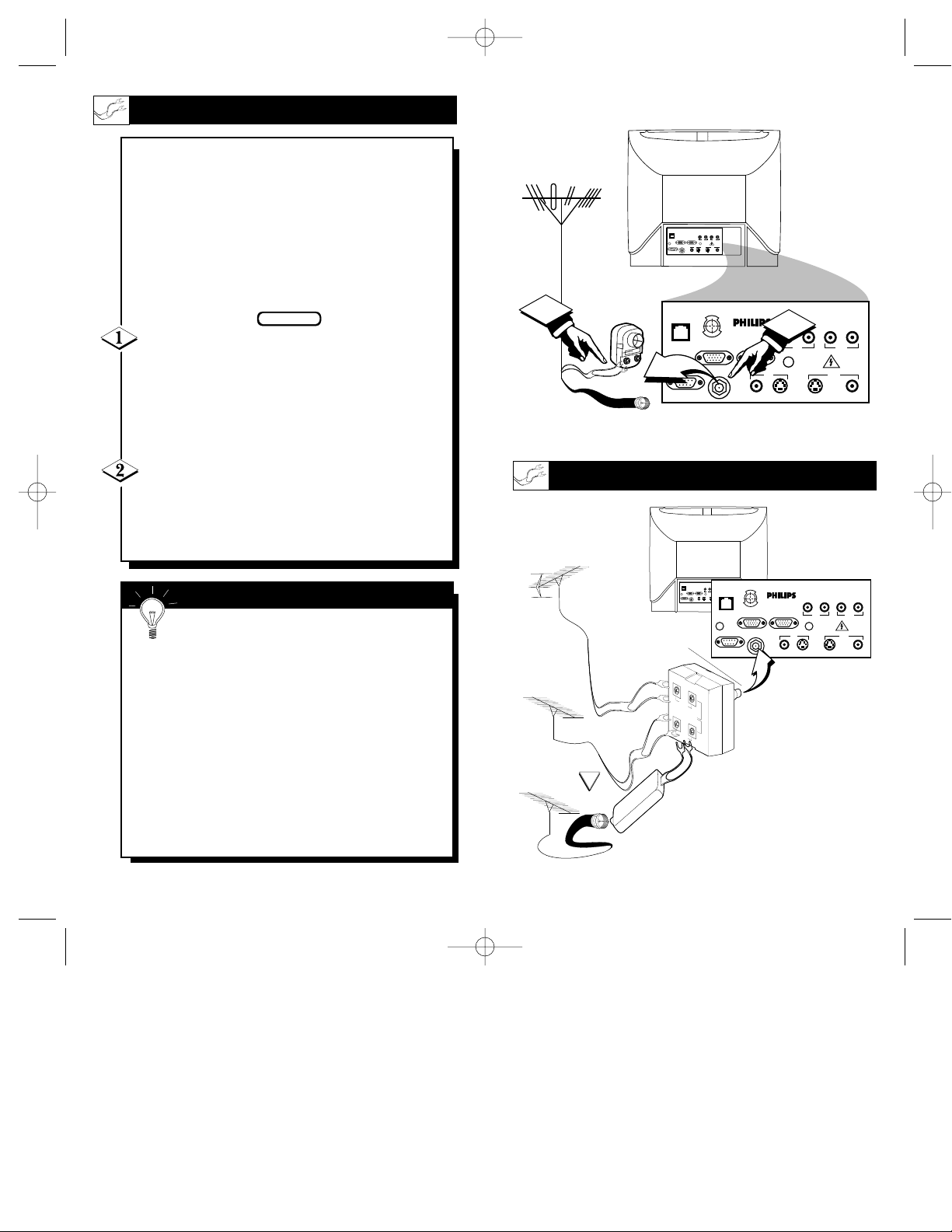
11
300 to 75Ω
Adapter
(483521827003)
Combination VHF/UHF
Antenna
(Outdoor or Indoor)
Twin Lead
Wire
Round Cable
75Ω
Back of TV
ScanCard II
Jack Panel
Round Cable 75Ω
75-300 Ohm Adapter
UHF/VHF Combiner
ScanCard II
Jack Panel
Back of TV
Outdoor UHF Antenna
(Twin Lead 300 Ohm)
Outdoor VHF
Antenna
(Twin Lead
300 Ohm)
Outdoor VHF
Antenna
(Round 75Ω
Cable)
Twin Lead
Wire
Round End
OPTIONAL HOOKUPS
10
A
combination antenna receives normal
broadcast channels (VHF 2-13 and UHF
14-69). Your connection is easy since there is
only one 75Ω (ohm) antenna plug on the
back of your TV - and that’s where the
antenna goes. (If you have more than one
antenna, please refer to the diagram at the
bottom of page 11 for additional hookups.)
If your antenna has a round cable (75 ohm)
on the end, then you're ready to connect it to the
TV.
If your antenna has flat twin-lead wire (300
ohm), you first need to attach the antenna wires to
the screws on a 300 to 75 ohm adapter.
Push the round end of the adapter (or anten-
na) onto the RF IN plug on the rear of the TV. If
the round end of the antenna wire is threaded,
screw it down tight.
BEGIN
Remember, be sure to set the TV for the
type signal you've connected.
To set the TV to select only the channel numbers
in your area see how to “Program" or "Add" channels in memory.
To order any optional accessory contact your dealer or call the toll-free accessory ordering number
(1-800-292-6066):
• UHF/VHF Combiner: (SBV1133AO1)
• 75-300 Ohm Adapter: (SBV1113AO1)
• 300-75 Ohm Adapter: (483521827003)
SMART HELP
ANTENNA HOOKUPS
SCAN 2 10/3/00 10:49 AM Page 10
1
SMARTSMART
PLUGPLUG
RS 232RS 232
CLONE
PORT
VGA INVGA IN VGA OUTVGA OUT
RS 232
RF INRF IN
VIDEOVIDEO
AUDIOAUDIO
VIDEOVIDEO
AUDIOAUDIO
ININ OUTOUT
OUTOUTININ
S-VIDEOS-VIDEOS-AUDIOS-AUDIO S-AUDIOS-AUDIO
S-VIDEOS-VIDEO
U
C
S
O
F
E
D
N
E
H
C
A
N
VGA IN VGA OUT
RF IN
ScanCard II
S-VIDEO
VIDEO
2
VIDEO
AUDIO
IN OUT
OUTIN
S-VIDEOVGA/S-AUDIO S-AUDIO
AUDIO
SMARTSMART
PLUGPLUG
VIDEOVIDEO
AUDIOAUDIO
VIDEOVIDEO
AUDIOAUDIO
SMART
VGA INVGA IN VGA OUTVGA OUT
ININ OUTOUT
O
F
PLUG
RF INRF IN
OUTOUTININ
RS 232RS 232
S-VIDEOS-VIDEOS-AUDIOS-AUDIO S-AUDIOS-AUDIO
S-VIDEOS-VIDEO
E
N
RS 232
H
VGA IN VGA OUT
UHF
300Ω
VHFV
VHF
OR
75-300 Ω ADAPTER
U
C
S
E
C
A
N
RF IN
D
ScanCard II
VIDEO
S-VIDEO
VIDEO
AUDIO
IN OUT
OUTIN
S-VIDEOS-AUDIO S-AUDIO
AUDIO
Page 7
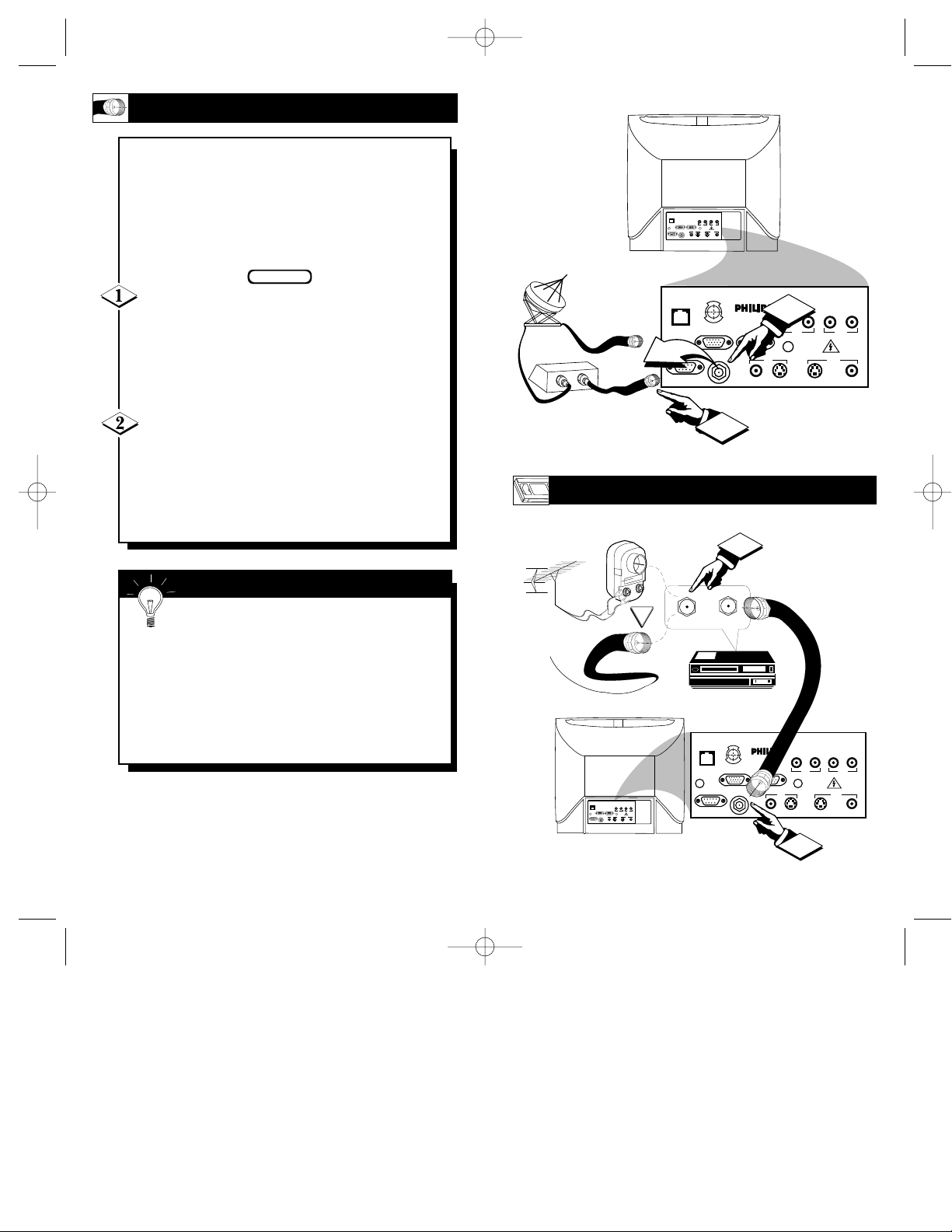
13
OPTIONAL VCR HOOKUP
Round Cable
75Ω Supplied
with VCR
VCR
Outdoor VHF/UHF
Antenna
300 to 75Ω Ohm
Adapter
Cable TV signal
Back of TV
ScanCard II
Jack Panel
Back of TV
Round Cable
75Ω Ohm
Cable TV Converter Box
Connection
Cable TV Company
ScanCard II
Jack Panel
12
Y
our Cable TV input into your home may
be a single (75 ohm) cable, or a
Converter Box installation. In either case the
connection to the TV is very easy. Just put
the threaded end of the cable signal to the
TV's antenna plug and screw it down tight.
If your Cable TV signal is a single round
cable (75 ohm) then you're ready to connect to
the TV.
If you have a Cable TV Converter Box:
Connect the Cable TV signal to the Cable Signal
IN(put) plug on the Converter.
Connect the Cable TV cable to the RF IN
plug on the TV.
If you have a Cable TV Converter Box:
Connect the OUT(put) plug from the Converter to
the RF IN plug on the TV (connecting cable supplied with the Converter.)
BEGIN
Remember, set the TV to the “Cable TV
Mode.” Then, to select only the channel
numbers on your Cable system see “Auto
Program" (refer to page 33 for both features).
If you use a Cable Converter box, set the TV to
the same channel as the converter's CH 3/4 switch
(on the rear of the converter.)
SMART HELP
CABLE TV HOOKUP
SCAN 2 10/3/00 10:49 AM Page 12
SMARTSMART
PLUGPLUG
VIDEOVIDEO
VIDEOVIDEO
AUDIOAUDIO
AUDIOAUDIO
VGA INVGA IN VGA OUTVGA OUT
ININ OUTOUT
RF INRF IN
OUTOUTININ
RS 232RS 232
S-VIDEOS-VIDEO
S-VIDEOS-VIDEOS-AUDIOS-AUDIO S-AUDIOS-AUDIO
CLONE
U
C
S
O
F
PORT
E
D
N
E
H
C
A
N
VGA IN VGA OUT
RF IN
OUT
IN
RS 232
ScanCard II
S-VIDEO
VIDEO
2
VIDEO
AUDIO
IN OUT
OUTIN
S-VIDEOVGA/S-AUDIO S-AUDIO
AUDIO
OR
SMARTSMART
PLUGPLUG
VIDEOVIDEO
AUDIOAUDIO
VGA INVGA IN VGA OUTVGA OUT
RF INRF IN
RS 232RS 232
VIDEOVIDEO
ININ OUTOUT
OUTOUTININ
S-VIDEOS-VIDEO
S-VIDEOS-VIDEOS-AUDIOS-AUDIO S-AUDIOS-AUDIO
IN FROM ANT.
AUDIOAUDIO
CLONE
PORT
RS 232
1
1
OUT TO TV
U
C
S
O
F
E
N
E
H
C
A
N
VGA IN VGA OUT
RF IN
D
ScanCard II
VIDEO
S-VIDEO
2
VIDEO
AUDIO
IN OUT
OUTIN
S-VIDEOVGA/S-AUDIO S-AUDIO
AUDIO
Page 8

15
Video RCAPhono Plug Cable
(not supplied)
Optional VCR
Rear Jacks of the
ScanCard II Assembly
Optional Hook Up of Second TV Using
Loop-Thru Outputs
Audio
RCA
Phono
Plug
Cable
(not sup-
plied)
Jack Panel of
Optional Mono
VCR
Back of TV
Front Control Panel of TV
AUDIO/VIDEO INPUTS
Y
ou can view the playback of VCR tapes
(Video Disc Players, Camcorders, etc.) by
using the AUDIO and VIDEO INPUT jacks
(on the ScanCard II Cover assembly).
For example: Use the following steps to view
the playback of a pre-recorded VCR tape
Connect the VIDEO and AUDIO IN(put)
jacks on the TV to the AUDIO and VIDEO
OUT(put) jacks on the VCR.
Press the CHANNEL ▼ button three chan-
nels below the lowest broadcast channel to activate the AUX inputs.
Turn the VCR ON. Insert a pre-recorded tape
into the VCR. Press PLAY on the VCR to view
the tape on the TV.
BEGIN
Remember, when your through using the
A/V INPUT (OUTPUT) jacks, change the
channel number back to the desired viewing channel (or the screen will remain blank).
NOTE: If you have a stereo VCR, “Y”
Connectors are available (from your dealer or
Parts Information Center 1-800-292-6066) to connect to the audio input on the TV.
SMART HELP
14
SCAN 2 10/3/00 10:49 AM Page 14
▼ ▲
SLEEP
SMARTSMART
PLUGPLUG
VIDEOVIDEO
VGA INVGA IN VGA OUTVGA OUT
RF INRF IN
RS 232RS 232
S-VIDEOS-VIDEO
CLONE CLONE
PORTPORT
RS 232RS 232
O
F
E
N
H
VGA INVGA IN VGA OUTVGA OUT
A
ININ OUTOUT
C
AUDIOAUDIO
N
MENU
VIDEOVIDEO
S-VIDEOS-VIDEOS-AUDIOS-AUDIO S-AUDIOS-AUDIO
U
S
C
RF INRF IN
OUTOUTININ
E
▲
CC
2
AUDIOAUDIO
D
▼
CH
1
ScanCard II
▼
–
VIDEOVIDEO
S-VIDEOS-VIDEO
VOL
POWER
▲
+
AUDIOAUDIO
VIDEOVIDEO
ININ OUTOUT
OUTOUTININ
S-VIDEOS-VIDEOVGA/S-AUDIOVGA/S-AUDIO S-AUDIOS-AUDIO
SMARTSMART
PLUGPLUG
AUDIOAUDIO
CLONECLONE
PORTPORT
RS 232RS 232
3
U
C
S
O
F
E
D
N
E
H
C
A
N
VGA INVGA IN VGA OUTVGA OUT
RF INRF IN
ScanCard II
ANTENNA
OUT
ANTENNA
IN
VIDEOVIDEO
S-VIDEOS-VIDEO
OUTOUT
VIDEOAUDIO
IN
IN
AUDIOAUDIO
VIDEOVIDEO
ININ OUTOUT
OUTOUTININ
S-VIDEOS-VIDEOVGA/S-AUDIOVGA/S-AUDIO S-AUDIOS-AUDIO
AUDIOAUDIO
Page 9

17
Optional S-VHS VCR
Rear Jacks of the
ScanCard II Assembly
Back of TV
Front Control Panel of TV
S-VIDEO
Cable
(supplied with optional
S-VHS VCR)
Audio RCA Phono
Plug Cable
(not supplied)
Jack Panel of
Optional S-VHS VCR
Optional VGA/S-AUDIO; S-VIDEO Hook
Up of Second TV Using Loop-Thru Outputs
S-VIDEO INPUTS
T
he S(uper)-Video connection on the rear
of the TV can give you better picture
detail and clarity, for the playback of S-VHS
VCR tapes, rather than the normal antenna
picture connections.
Note: The VCR (or accessory device) must
have a S-VIDEO OUT(put) jack in order for
you to complete the steps and connections
shown to the right.
Connect the S-VIDEO (S-VHS) OUT(put)
jack from the VCR (or other source) to the VVIDEO IN(put) jack on the TV.
Normally the S-VIDEO connecting cable will be
supplied with accessory devices supplied with a
S-VIDEO jack.
Press the CHANNEL ▼ button two channels
below the lowest broadcast channel to activate
the S-VIDEO inputs/outputs.
Turn the VCR ON. Insert a pre-recorded S-
VHS tape into the VCR. Press PLAY on the VCR
to view the tape on the TV.
BEGIN
Remember, after it is connected an easy
way to select the S-VIDEO mode is to scan
two channels below the lowest broadcast channel.
NOTE: If you have a stereo VCR, “Y”
Connectors are available (from your dealer or
Parts Information Center 1-800-292-6066) to connect to the audio input on the TV.
SMART HELP
16
SCAN 2 10/3/00 10:49 AM Page 16
SMARTSMART
PLUGPLUG
CLONECLONE
PORTPORT
RS 232RS 232
MENU
▼ ▲
SLEEP
▼
▲
CC
2
VIDEOVIDEO
VIDEOVIDEO
AUDIOAUDIO
AUDIOAUDIO
OUTOUTININ
RS 232RS 232
S-VIDEOS-VIDEO
S-VIDEOS-VIDEOS-AUDIOS-AUDIO S-AUDIOS-AUDIO
U
C
S
O
F
E
ScanCard II
D
N
E
H
C
A
N
VGA INVGA IN VGA OUTVGA OUT
1
RF INRF IN
CH
–
VIDEOVIDEO
S-VIDEOS-VIDEO
POWER
▲
+
VIDEOVIDEO
AUDIOAUDIO
ININ OUTOUT
SMARTSMART
OUTOUTININ
PLUGPLUG
S-VIDEOS-VIDEOVGA/S-AUDIOVGA/S-AUDIO S-AUDIOS-AUDIO
AUDIOAUDIO
VOL
▼
3
U
C
E
N
VGA INVGA IN VGA OUTVGA OUT
F
H
O
A
RF INRF IN
N
CLONECLONE
PORTPORT
RS 232RS 232
S
D
E
C
ScanCard II
S-VIDEO
VIDEOVIDEO
S-VIDEOS-VIDEO
OUTOUT
OUT
ANTENNA
AUDIOAUDIO
ININ OUTOUT
VIDEOAUDIO
IN
IN
IN
VIDEOVIDEO
OUTOUTININ
S-VIDEOS-VIDEOVGA/S-AUDIOVGA/S-AUDIO S-AUDIOS-AUDIO
AUDIOAUDIO
Page 10

19
NOTE: The ScanCard™ VGA connections allow for
the use of WINDOWS 95™, WINDOWS™, WIN-
DOWS™ based programs, DOS, and MACINTOSH™
based programs only.
PC CONNECTIONS
MACINTOSH CONNECTIONS
BACK OF THE
TV WITH
SCANCARD II
VGA Cable
Desk Top/Lap Top
Personal Computer
VGA/RGB
Output
VGA IN(put)
BACK OF THE
TV WITH
SCANCARD II
VGA Cable
Desk Top/Lap Top
Macintosh
Computer
(also Power
Macintosh)
VGA/RGB
Output
VGA IN(put)
VGA MAC
Adapter
NOTE: The VGA/S-Audio
Input can be used for
audio reproduction
coming from a PC.
NOTE: The VGA/S-Audio
Input can be used for
audio reproduction
coming from a Macintosh.
VGA INPUTS
T
he main purpose of the ScanCardII is its
ability to convert VGA/SVGA inputted
data from a computer to S-Video data, thus
showing computer generated graphics on the
screen of a Philips SmartCard TV.
The following are suggested computer connections to the ScanCard II.
It is always a good idea to remove the TV’s,
and the computer’s, AC power cords from the
wall socket before beginning the connections.
The VGA Input accepts signals from VGA and
MAC compatible computers without the need for
any additional hardware.
For PC Applications: Plug the VGA cable into
the VGA Input terminal on the back of a commercial TV equipped with the Philips ScanCard II.
Then attach the other end of the VGA cable to the
VGA (RGB) Output on the back of the computer.
(Secure the plugs by tightening the thumb screws.)
Reattach the AC Power cords to the wall sockets
before powering on the units.
For Macintosh Applications: Connect the
MAC/VGA adapter to the RGB Output of a
Macintosh Series computer. Then firmly plug the
VGA cable into both the VGA Input on the TV and
the MAC/VGA adapter on the computer. (Secure
the plugs by tightening the thumb screws.)
Reattach the AC Power cords to the wall sockets
before powering on the units.
Please note: If using an educational 5200 series
Macintosh, the addition of a POWER R adapter
must be installed when making this connection.
Using the Channel ▼ button select one channel
below your lowest available broadcast channel to
access the VGA Inputs.
BEGIN
18
SCAN 2 10/3/00 10:49 AM Page 18
CLONE
PORT
RS 232
U
C
S
O
F
E
ScanCard II
D
N
E
H
C
A
N
VGA IN VGA OUT
RF IN
VIDEO
S-VIDEO
VIDEO
AUDIO
IN OUT
OUTIN
S-VIDEOVGA/S-AUDIO S-AUDIO
AUDIO
CLONE
PORT
RS 232
U
C
S
O
F
E
ScanCard II
D
N
E
H
C
A
N
VGA IN VGA OUT
RF IN
S-VIDEO
VIDEO
AUDIO
IN OUT
S-VIDEOVGA/S-AUDIO S-AUDIO
VIDEO
AUDIO
OUTIN
Page 11

20
T
he ScanCard II assembly is equipped
with a RS 232 (Serial) Input. When a
computer’s Serial Port is hooked to the Scan
Card II through the RS 232 input, the computer can control the various functions of the
television. (Refer to SmarkLink specifications
available under DNA.)
It is always a good idea to remove the TV’s,
and the computer’s, AC power cords from the
wall socket before beginning the connections.
The RS 232 (Serial) Input accepts signals from
VGA and MAC compatible computers that have
external Serial Ports.
For PC/MACs with Serial Ports: Plug a
Serial cable into the RS 232 (Serial) Input terminal on the back of a commercial TV equipped
with the ScanCard II. Then attach the other end of
the Serial cable to the Serial Output Port on the
back of the computer. (Secure the plugs by tightening the thumb screws.)
Reattach the AC Power cords to the wall sock-
ets before powering on the units.
BEGIN
RS 232 INPUT
BACK OF THE TV
WITH SCANCARD II
Serial Cable
Desk Top/Lap Top
PC/Macintosh Computer
with a Serial Port
(also Power Macintosh)
Serial Output
RS 232 IN(put)
RS 232 CONNECTIONS
21
TELEVISION OPERATION
Press the POWER button to turn the TV ON.
Press the VOLUME UP(▲) or DOWN (▼)
button to adjust the sound level.
Press the CHANNEL UP (▲) or DOWN (▼)
button to select TV channels.
The TELEVISION CONTROL PANEL
MENU ▼ Button - Brings the on-screen menu up and allows
the user to scroll thru the options.
SLEEP Button - With the ScanCard II assembly installed, the
Sleep option at the television control panel is rendered inoperable.
MENU ▲ Button - Will clear the screen when the on-screen
menu is visible.
CC Button - Will bring up the Closed Captioning options.
Repeated pressing of this button will allow the user to change
those options. (Will not operate when tuned to the VGAchannel.)
CHANNEL ▼▲ Buttons - Use these buttons to scroll thru
available channels. These buttons will also allow you to scroll
thru the on-screen menu options when displayed.
VOLUME ▼▲ (- or +) Buttons - Use these buttons to
increase or decrease the audio level output of the TV. The (-) or
(+) function for these buttons is to select certain options from
within the on-screen menu.
POWER Button - Toggle between turning the TV ON and OFF.
Note: The KEYBOARD Buttons can be controlled using the
“FRONT KEYPAD” feature within the “Commercial Settings”
menu (refer to page 30 for more details).
SCAN 2 10/3/00 10:49 AM Page 20
BEGIN
CLONE
PORT
RS 232
U
C
S
O
F
E
D
N
E
H
C
A
N
VGA IN VGA OUT
RF IN
ScanCard II
VGA/S-AUDIO
VIDEO
S-VIDEO
VIDEO
AUDIO
IN OUT
OUTIN
S-VIDEO
AUDIO
S-AUDIO
▼ ▲
MENU
SLEEP
▼
▲
CC
6
CH
3
VOL
▼
▲
+
–
POWER
2
1
Page 12

REMOTE OPERATION
T
he ScanCard II Remote Control is used to operate
the functions of this ScanCard II television as well
as some other PCEC Commercial chassis units.
The three buttons located at
the bottom of the remote
(labeled SVID, VGA, and
AUX) are called “Direct
Channel Select” buttons and
are used to select the desired
input source directly from the
jack panel.
To access the on-screen menu
system follow the steps below:
Press the POWER button to
turn the TV on.
Press the SELECT (M) button to display the on-screen
menu options. These Menus
will vary depending on the
tuned channel. (Refer to the
On-Screen Menu section,
pages 24-34.)
Press the CURSOR buttons to navigate through the
on-screen menus and make
menu changes.
NOTE: If performing a setup
with a TH374AH Setup
Remote, see Remote Control
Instructions - part #IB7166E002 for details. All the functions will operate normally with the exception of the
BRIGHTNESS and PICTURE controls. The ScanCard II
will store a separate set of BRIGHTNESS and PICTURE
settings for VGA and non-VGA display modes. This allows
the display to be optimized for computer generated graphics
or settings that are pleasing for off-air/accessory viewing
(used with VCR, Video Disc Player, CD-i Player, etc.).
2322
ZOOM - Press this button to enlarge the image
on screen 2 times its normal viewing size. (Use
the CURSOR buttons to pan up, down, and
left, right.) Note: This feature ONLY works
when tuned to the VGA channel.
STATUS/EXIT -
Press this button to
clear the screen of
the menu and save
function changes
made within the onscreen menus.
SELECT (M) -
Press this button to
bring up the onscreen menu
options. Also may
be used to select
items within the
menu.
CH(annel) - Press
this button to scroll
through all available
channels.
A/CH - Press this
button to toggle
between the present
and last viewed
channels.
NUMBERED
BUTTONS - Press
these buttons to
directly access any
available channel. (If
a single digit channel is chosen, press
0 first. Example for
channel 6; first press
0, then 6.)
VOL(ume) - Press
this button to adjust
the sound level of
the TV.
ADJUST - Press
this button to adjust
the TV’s picture or
the VGA image.
CC - Press this button to bring the
Closed Captioning
option to the screen.
Note: This feature
WILL NOT work
when tuned to the
VGA channel.
POWER -
Press this
button to turn
the TV ON or
OFF.
SVID - Press
this button to
tune the TV to
the ScanCard
II’s S-VIDEO
Input jack.
AUX - Press this
button to tune the
TV to the ScanCard
II’s AUXILIARY
Input jack.
VGA - Press this
button to tune
the TV to the
ScanCard II’s
VGA Input jack.
REMOTE OPERATION
L
isted below is a brief description of each -
-button’s function. Some buttons may perform
more than one function depending on the mode or
function selected.
CURSOR KEYS -
Press these buttons
(▲ ▼
© § ) to
scroll or move
through the onscreen menu or to
adjust the picture in
certain features.
MUTE - Press this
button to turn the
sound OFF on the
TV. Press again to
return the sound to
its previous level.
SCAN 2 10/3/00 10:49 AM Page 22
ZOOM
STATUS
EXIT
E
C
L
E
T
S
-
+
M
A/CH
VOL
MUTE
1
ADJUST
CC
POWER
ScanCard II
2
4
5
8
7
0
STATUS
CH
ZOOM
-
EXIT
E
C
L
E
T
S
+
M
3
6
9
AUXVGASVID
A/CH
VOL
MUTE
CH
ADJUST
CC
POWER
ScanCard II
1
2
4
5
8
7
0
3
6
9
AUXVGASVID
Page 13

2524
ON-SCREEN MENU CONTROLS
Y
ou can make some adjustments to the TV pic-
ture using the TV PICTURE SETUP or the
VGA PICTURE SETUP on-screen menu. Follow
the steps below for the proper procedure.
Press the SELECT (M) button on the remote
control to see the on-screen menu.
Press the MENU ▼▲ on the remote control
repeatedly to move the highlight to the desired
feature to change or adjust.
Press the MENU
§ © buttons on the
remote control to adjust or change the highlighted
feature.
Press the STATUS/EXIT button on the
remote control to clear the screen when finished.
BEGIN
PICTURE ADJUSTMENTS
TV PICTURE SETUP M
ENU
Adjust BRIGHTNESS
using the + or – buttons.
Adjust PICTURE
using the + or – buttons.
RESTORE PRESETS
using the + button.
W
hen viewing normal broadcast channels only the
BRIGHTNESS and PICTURE controls can be
changed, or the TV can be restored to its PRESETS
(RESTORE PRESETS). This menu can be accessed by
the MENU or ADJUST buttons on the remote.
EXIT the menu using
the + or - buttons.
S
canCard II has two different operation modes;
Consumer and Commercial. When in the Consumer
mode, all available menu items and tuning options are
fully enabled (with the exception of the COMMERCIAL SETTING menu). Access to ScanCard II’s internal “TV PICTURE SETUP,” “VGA PICTURE
SETUP,” and the TV’s “SETUP” menus can be selected with the supplied ScanCard II remote control. When
in the Commercial mode, limited menu access can be
obtained. Only the “TV PICTURE SETUP,” and
“VGA PICTURE SETUP” menus are accessible with
the supplied ScanCard II remote control.
Brightness Control - Press the (+) or (-) button to adjust
the brightness to the desired level. The (+) button increases
the picture BRIGHTNESS while the (-) button will
decrease the picture BRIGHTNESS.
Pictur
e Control - Press the (+) or (-) button to adjust the
picture quality. This controls the pictures clarity and contrast.
Restore Presets - Pressing the (+) button will restore the
menu options back to the preset options set by the setup
technician.
Exit Menu - Press the (+) or (-) button to clear the onscreen menu from the picture.
TV PICTURE SETUP DESCRIPTIONS
SCAN 2 10/3/00 10:49 AM Page 24
TV PICTURE SETUP
BRIGHTNESS - - - - - - - - - -
PICTURE - - - - - - - - - RESTORE PRESETS
EXIT MENU
PRESS + OR – TO CHANGE
TV PICTURE SETUP
BRIGHTNESS - - - - - - - - - PICTURE - - - - - - - - - -
RESTORE PRESETS
EXIT MENU
PRESS + TO RESTORE
TV PICTURE SETUP
BRIGHTNESS - - - - - - - - - -
PICTURE - - - - - - - - - -
RESTORE PRESETS
EXIT MENU
PRESS + OR – TO CHANGE
TV PICTURE SETUP
BRIGHTNESS - - - - - - - - - PICTURE - - - - - - - - - -
RESTORE PRESETS
EXIT MENU
PRESS + OR - TO EXIT
Page 14

2726
VGA PICTURE SETUP MENU
Adjust BRIGHTNESS
using the + or – buttons.
Adjust PICTURE
using the + or – buttons.
Press the – button to mute the audio, or the +
button to turn the audio ON (VGA mode only)
Press the – button if using a Macintosh,
or the + button if using a PC.
Restore PRESETS
using the + button.
EXIT the on-screen menu
using the + button.
W
hen using the VGA INPUTS the BRIGHTNESS, PICTURE,
AUDIO, TYPE of INPUT (PC or MAC) and IMAGE adjustments
(ADJUST VGA IMAGE) can be changed or adjusted. The TV picture can
also be restored to its original PRESETS (RESTORE PRESETS).
Press the + button to access the VGA
IMAGE ADJUSTMENT menu.
When you access the ADJUST VGA
IMAGE menu, the following items
can be changed or adjusted:
HORIZONTALSIZE and
POSITION, VERTICALSIZE and
POSITION, VGA GAIN LEVEL,
COLOR INTENSITY, and a FLICK-
ER FILTER. For more details, refer
to VGA IMAGE ADJUSTMENT
menu on page 28.
ADJUST VGA IMAGE
Adjust VGA Image - Press the (+) or (-) button to activate
the “VGA IMAGE ADJUSTMENT” menu. (Refer to page
28 for more details.)
Brightness Control - Press the (+) or (-) button to adjust
the brightness to the desired level. The (+) button increases
the picture BRIGHTNESS while the (-) button will
decrease the picture BRIGHTNESS.
Input Type - Press the (+) or (-) button to select between
the PC mode or the Macintosh mode. ScanCard II optimizes screen geometries and configuration information for
the selected compatible platform.
Picture Control - Press the (+) or (-) button to adjust the
picture quality. This controls the pictures clarity and contrast..
VGA Audio - Press the (+) or (-) button to activate or
mute the audio signal whenever the VGA channel is tuned.
With VGAAUDIO “OFF” selected, all volume and mute
commands will be ignored.
Restore Presets - Pressing the (+) button will restore the
menu options back to the preset options set by the setup
technician.
Exit Menu - Press the (+) or (-) button to clear the onscreen menu from the picture.
VGA PICTURE SETUP DESCRIPTIONS
SCAN 2 10/3/00 10:49 AM Page 26
VGA PICTURE SETUP
BRIGHTNESS - - - - - - - - - -
PICTURE - - - - - - - - - VGA AUDIO ON
INPUT TYPE PC
ADJUST VGA IMAGE
RESTORE PRESETS
EXIT MENU
PRESS + / – TO ADJUST
VGA PICTURE SETUP
BRIGHTNESS - - - - - - - - - -
PICTURE - - - - - - - - - -
VGA AUDIO ON
INPUT TYPE PC
ADJUST VGA IMAGE
RESTORE PRESETS
EXIT MENU
- FOR OFF / + FOR ON
VGA PICTURE SETUP
BRIGHTNESS - - - - - - - - - -
PICTURE - - - - - - - - - VGA AUDIO ON
INPUT TYPE PC
ADJUST VGA IMAGE
RESTORE PRESETS
EXIT MENU
PRESS + TO ADJUST IMAGE
VGA PICTURE SETUP
BRIGHTNESS - - - - - - - - - -
PICTURE - - - - - - - - - VGA AUDIO ON
INPUT TYPE PC
ADJUST VGA IMAGE
RESTORE PRESETS
EXIT MENU
PRESS + TO RESTORE
VGA PICTURE SETUP
BRIGHTNESS - - - - - - - - - -
PICTURE - - - - - - - - - -
VGA AUDIO ON
INPUT TYPE PC
ADJUST VGA IMAGE
RESTORE PRESETS
EXIT MENU
PRESS + / – TO ADJUST
VGA PICTURE SETUP
BRIGHTNESS - - - - - - - - - -
PICTURE - - - - - - - - - VGA AUDIO ON
INPUT TYPE PC
ADJUST VGA IMAGE
RESTORE PRESETS
EXIT MENU
- FOR MAC / + FOR PC
VGA PICTURE SETUP
BRIGHTNESS - - - - - - - - - -
PICTURE - - - - - - - - - VGA AUDIO ON
INPUT TYPE PC
ADJUST VGA IMAGE
RESTORE PRESETS
EXIT MENU
PRESS + TO EXIT
Page 15

29
28
VGA IMAGE ADJUSTMENT MENU
T
he VGA IMAGE ADJUSTMENT menu will allow you to move the
positioning of the display both vertically and horizontally and
change its size in both directions. The VGA GAIN LEVEL can be set
LOW or HIGH along with the picture’s COLOR INTENSITY. If flickering
in the display becomes a problem, ScanCard II has a built-in FLICKER
FILTER that can be manually turned ON or OFF.
Press the – button to NARROW the display,
or the + button to WIDEN the display.
Press the – button to SHORTEN the display,
or the + button to make the display TALLER.
Press the – button to move the display LEFT,
or the + button to move the display RIGHT.
Press the – button to move the display UP,
or the + button to move the display DOWN.
Press the – button to set the VGA GAIN to
LOW, or the + button to set the gain to HIGH.
Press the – button to set the COLOR INTENSI-
TY to LOW, or the + button to set it to HIGH.
To activate the FLICKER FILTER, press the
+ button. To turn it OFF press the – button.
Press the + button to EXIT the
on-screen menu.
Horizontal Size - Press the (+) or (-) button to adjust the
HORIZONTAL size of the scanned picture on the screen.
The (+) button will increase the size horizontally, while the
(–) button will decrease the size horizontally.
Vertical Size - Press the (+) or (-) button to adjust the VERTICAL size of the scanned picture on the screen. The (+)
button will increase the size vertically, while the (–) button
will decrease the size vertically.
Horizontal Position - Press the (+) or (-) button to adjust
the HORIZONTAL position of the scanned picture on the
screen. Picture will move left to right (+), or right to left (–).
Vertical Position - Press the (+) or (-) button to adjust the
VERTICALposition of the scanned picture on the screen.
Picture will move down (+), or up (–).
VGA
Gain Level
- Press the (+) or (-) button to set the
VGA Gain Level LOW or HIGH. Because of signal differences from one VGA source to another, ScanCard II can
boost the video signal for a better display.
Color
Intensity - Press the (+) or (-) button to set the Color
Intensity to LOW or HIGH. Setting this feature to LOW can
help minimize burn-in and blooming problems common on
most television sets.
Flicker Filter - Press the (+) or (-) button to activate or
deactivate the filter. When “ON” this feature will greatly
improve image stability, but it also reduces image sharpness
and resolution.
Exit Menu - Press the (+) or (-) button to clear the onscreen menu from the picture.
VGA IMAGE ADJUSTMENT DESCRIPTIONS
SCAN 2 10/3/00 10:49 AM Page 28
VGA IMAGE ADJUSTMENT
HORIZONTAL SIZE
VERTICAL SIZE
HORIZONTAL POSITION
VERTICAL POSITION
VGA GAIN LEVEL HIGH
COLOR INTENSITY HIGH
FLICKER FILTER ON
EXIT MENU
- NARROWER / + WIDER
VGA IMAGE ADJUSTMENT
HORIZONTAL SIZE
VERTICAL SIZE
HORIZONTAL POSITION
VERTICAL POSITION
VGA GAIN LEVEL HIGH
COLOR INTENSITY HIGH
FLICKER FILTER ON
EXIT MENU
- LEFT / + RIGHT
VGA IMAGE ADJUSTMENT
HORIZONTAL SIZE
VERTICAL SIZE
HORIZONTAL POSITION
VERTICAL POSITION
VGA GAIN LEVEL HIGH
COLOR INTENSITY HIGH
FLICKER FILTER ON
EXIT MENU
- FOR LOW / + FOR HIGH
VGA IMAGE ADJUSTMENT
HORIZONTAL SIZE
VERTICAL SIZE
HORIZONTAL POSITION
VERTICAL POSITION
VGA GAIN LEVEL HIGH
COLOR INTENSITY HIGH
FLICKER FILTER ON
EXIT MENU
- FOR OFF / + FOR ON
VGA IMAGE ADJUSTMENT
HORIZONTAL SIZE
VERTICAL SIZE
HORIZONTAL POSITION
VERTICAL POSITION
VGA GAIN LEVEL HIGH
COLOR INTENSITY HIGH
FLICKER FILTER ON
EXIT MENU
- SHORTER / + TALLER
VGA IMAGE ADJUSTMENT
HORIZONTAL SIZE
VERTICAL SIZE
HORIZONTAL POSITION
VERTICAL POSITION
VGA GAIN LEVEL HIGH
COLOR INTENSITY HIGH
FLICKER FILTER ON
EXIT MENU
- UP / + DOWN
VGA IMAGE ADJUSTMENT
HORIZONTAL SIZE
VERTICAL SIZE
HORIZONTAL POSITION
VERTICAL POSITION
VGA GAIN LEVEL HIGH
COLOR INTENSITY HIGH
FLICKER FILTER ON
EXIT MENU
- FOR LOW / + FOR HIGH
VGA IMAGE ADJUSTMENT
HORIZONTAL SIZE
VERTICAL SIZE
HORIZONTAL POSITION
VERTICAL POSITION
VGA GAIN LEVEL HIGH
COLOR INTENSITY HIGH
FLICKER FILTER ON
EXIT MENU
PRESS + TO EXIT
Page 16

3130
P
ressing the “C” button on the T374AH Setup
remote control will show the “COMMERCIAL
SETTINGS” menu. This is an area that will only be
accessible to the installer when using the Setup
Remote. These options can’t be accessed with the supplied ScanCard II remote control.
Press the + or – button to change the
operation mode to COMMERCIAL
or CONSUMER.
Press the – button to turn the FRONT
KEYPAD “OFF” or the + button
to turn it “ON.”
Press the – button to turn the CABLE
MODE “OFF”, or the + button to turn it
“ON.” This allows the user to choose
between cable and broadcast modes
within the ScanCard II television.
Press the + or – button to choose an
initial Power On channel for the TV.
Press the + or – button to adjust an initial Power On volume level for the TV.
Press the + button to EXIT this menu.
COMMERCIAL SETTINGS MENU
Mode - Press the (+) or (-) button to change the TV’s oper-
ation mode. There are two different operating modes available, “CONSUMER” or “COMMERCIAL.” When the
ScanCard II is in the “CONSUMER” mode, all menu items
and tuning options are fully operational. In this mode the
user will be able to access the ScanCard II’s internal “TV
PICTURE SETUP,” “VGA PICTURE SETUP,” and the
TV’s “SETUP” menus with the ScanCard II remote control.
When ScanCard II is in the “COMMERCIAL” mode, only
the “TV PICTURE SETUP” and “VGA PICTURE
SETUP” menus will be accessible with the ScanCard II
remote control.
Front Keypad - Press the (–) button to turn the TV’s Front
Controls “OFF”, or press the (+) button to turn them “ON.”
When “FRONT KEYPAD” is “OFF” the TV can only be
operated with the Setup or ScanCard II remote control.
Cable Mode - Press the (–) button to turn the ScanCard II’s
Cable Mode “OFF”, or press the (+) button to turn it “ON.”
This feature allows the user to select either cable or broadcast mode on a SmartCard TV with ScanCard II installed.
When the CABLE MODE within ScanCard II is activated
the TV’s menu will be ignored.
On Channel - Press the (+) or (-) button to choose an initial Power On channel for the TV. Choose from STANDARD, AUX, VGA, SVIDEO, 2, 3, ..., 68, 69 when in the
broadcast mode. Or choose STANDARD, AUX, VGA,
SVIDEO, 1, 2, 3, ...., 124, 125 when in cable mode.
On Volume - Press the (+) or (-) button to set an initial
Power On volume level for the TV. When the STANDARD
option is selected, the ON VOLUME feature is disabled.
When enabled, a volume “bar” will be displayed which
indicates the current volume level. Pressing the (+) or (–)
buttons will allow the user to change the volume to a desirable setting.
Exit Menu - Press the (+) or (-) button to clear the onscreen menu from the picture.
COMMERCIAL SETTINGS DESCRIPTIONS
SCAN 2 10/3/00 10:49 AM Page 30
COMMERCIAL SETTINGS
MODE COMMERICAL
FRONT KEYPAD ON
CABLE MODE ON
ON CHANNEL VGA
ON VOLUME STANDARD
EXIT MENU
PRESS + OR – TO CHANGE
COMMERCIAL SETTINGS
MODE COMMERICAL
FRONT KEYPAD ON
CABLE MODE ON
ON CHANNEL VGA
ON VOLUME STANDARD
EXIT MENU
- FOR OFF / + FOR ON
COMMERCIAL SETTINGS
MODE COMMERICAL
FRONT KEYPAD ON
CABLE MODE ON
ON CHANNEL VGA
ON VOLUME STANDARD
EXIT MENU
- FOR OFF / + FOR ON
COMMERCIAL SETTINGS
MODE COMMERICAL
FRONT KEYPAD ON
CABLE MODE ON
ON CHANNEL VGA
ON VOLUME STANDARD
EXIT MENU
PRESS + OR - TO ADJUST
COMMERCIAL SETTINGS
MODE COMMERICAL
FRONT KEYPAD ON
CABLE MODE ON
ON CHANNEL VGA
ON VOLUME STANDARD
EXIT MENU
PRESS + OR - TO CHANGE
COMMERCIAL SETTINGS
MODE COMMERICAL
FRONT KEYPAD ON
CABLE MODE ON
ON CHANNEL VGA
ON VOLUME STANDARD
EXIT MENU
PRESS + TO EXIT
Page 17

33
32
iter described in the next step. In this mode the mute function
is disabled. Press the (-) button for “standard volume
up/down”, allowing normal volume control operation.
Press the VOLUME UP or VOLUME DOWN button to set
maximum level available. The range is made up of 63 steps
from minimum to maximum.
Press the (+) or (-) to choose between MAX(imum) volume
or the TURN ON volume. Press the VOLUME UP or VOLUME DOWN button to set either the MAX(imum) volume
level available, or the set TURN ON volume level. The range
is made up of 63 steps from minimum to maximum.
Cable
TV Mode - Press the (+) button to have the TV
receive cable channels 1 to 125 excluding channels 95, 96
and 97. Press the (-) button to have the TV receive the normal off-the-air channels 2-69.
Auto Pr
ogram - This function allows the TV to scan all the
channels and automatically program in memory all active
channels on the system. Press the (+) button to activate auto
programming. Press the (-) button at any time to stop this
function.
Add/Delete Channels
- This function allows individual
channels to be added or deleted from memory. Tune the
desired channel by using the CHANNEL UP/CHANNEL
DOWN buttons or by random access, and then press the (+)
or (-) button to either add or remove a channel from memory.
Labels
- This function will give a name, up to eight characters, to a channel. Press the (-) button to delete any existing
label. Press the (+) button to activate this function. Once in
modification display, a cursor will point to the position on
the label. The Menu ▲▼ buttons (on the T374AH remote)
will scan through the available character set. The (+) and (-)
buttons will move the cursor to the next position on the label.
A total of 32 channels may be labeled. (DO NOT LABEL
S-VIDEO)
Reminder
- Press the (+) button to allow the continuous display of the current channel number. Press the (-) button and
the channel number will appear for only a few seconds after
the channel change and then disappear. (With ScanCard II
installed REMINDER should be in the OFF position.)
On Channel
- This function will determine what channel the
TV will tune to at initial turn ON. Tune any channel and
press the (+) button. The TV will tune to that channel every
time it is turned ON. Press the (-) button and the TV will, at
turn on, tune to the last channel tuned before turn OFF. (Will
not operate with the ScanCard II installed.)
ON-SCREEN MENU CONTROLS
TYPICAL TV FEATURES
D
epending on the model of your television and its
features, some or all of the display functions and
features described below will be valid. Certain feature
operations which are found both in the Commercial and
Consumer modes can be selected and adjusted in the
same manner (such as Language, Reminder, Color
Adjustments, etc.).
To perform setup operations for the TV, a T374AH
remote with its TV Setup, Guest, and Data
Communication mode capabilities can be used. With the
use of the T374AH remote, a number of Commercial
setup and verification procedures can be performed. (See
T374AH Remote Control Instructions-part # IB7166E002
for details.)
DESCRIPTION OF FEATURES
ColorAdjustments - Press the (+) or
(-) button to adjust the brightness to
the desired level.
Press the (+) or (-) button to adjust the
picture to the desired level.
Press the (+) or (-) button to adjust the
color to the desired level. Press the (+)
or (-) to adjust the tint to the desired
level.
Press the (+) or (-) button to adjust the
sharpness to the desired level.
V
olume controls - Press the (+) or (-)
button to set the maximum allowable
volume available from the keyboard or
the Guest transmitter.
Press the (+) button to disable the normal functioning of the volume control.
This forces the volume to the maximum level allowed by the volume lim-
BRIGHTNESS
PICTURE
COLOR
TINT
SHARPNESS
CABLE
PROGRAM
CH ADD/DEL
LABELS
REMINDER
ON CHANNEL
POWER ON
DISPLAYS
KEYBOARD
SMART SND
INPUT
ESP MODE
CHAN GUIDE
LANGUAGE
A/V MUTE
CHAN BLANK
VOL FORCE
MIN VOLUME
MAX VOLUME
ON VOLUME
SPEAKER
BASS BOOST
VOLUME BAR
EXIT
SETUP MENU
SCAN 2 10/3/00 10:49 AM Page 32
Page 18

35
34
CLOSED CAPTIONING
Closed Captioning modes
when pressing the CC button
on the remote control.
C
losed Captioning allows you to read the voice con-
tent of television programs on the TV screen.
Designed to help the hearing impaired this feature uses
on-screen “text boxes” to show dialogue and conversations while the TV program is in progress. This feature
will not work when tuned to the VGA channel.
Press the CC button on the remote control to bring
up the Closed Captioning on-screen display.
Press the CC button repeatedly to select the
desired Closed Caption mode.
For example: CAPTION 1.
CAPTION 1, 2, 3, or 4: dialogue (and descriptions) for
the action on the captioned TV program shows onscreen.
TEXT 1, 2, 3, or 4: often used for channel guide, schedules, or bulletin board information for CC programs.
Note: Usually “CAPTION 1” is the most used mode to
view captioned material.
After making your Closed Caption mode selection
the menu will time out and disappear from the screen
within a few seconds.
Closed Captioning material (if available on the current
selected TV program) will appear on the TV screen.
To cancel, select the OFF mode within the Closed
Captioning feature.
Note: Not all TV programs and product commercials are
made for broadcast with Closed Captioning (CC) information included.
The Closed Caption feature does not
work on the VGAchannel.
BEGIN
Power On - Press the (+) button for the “POWER FORCED
ON” mode. This disables the normal ON/OFF control and
the receiver will be activated once AC power is applied. The
“Sleep Timer” function is disabled and the set may not be
turned OFF except by removing power. Press the (-) button
for normal “POWER ON/OFF” control.
Displays
- The “NO DISPLAYS” function disables any onscreen displays, except the Sleep Timer and the Mute. Press
the (+) button to activate this function and the (-) button for
standard displays. (With the ScanCard II installed set
Displays to STANDARD.)
Keyboard
- The “OFF” selection lockouts or disables all
functions from the TV’s front control panel. (This function
will not work with the ScanCard II installed.)
Smar
t Sound - The “ON” selection controls the TV volume
to smooth out level during program changes and commercial
breaks.
ESP
Mode - The “ESP MODE” function will automatically
turn OFF the set if it has been ON continuously for the time
duration shown. Press the (+) button to activate the function
and set the time limit by random access of the desired duration (up to 99 hours). Press the (-) button for normal TV
operation.
Channel Guide
- Press the (+) button to enable the Channel
Guide feature. Press the (-) button to disable the function.
A/V
Mute - The “ON” setting goes to a blank Video Blue
background, and the TV audio is muted. “OFF” returns the
TV to Antenna signal source screen.
Channel Blank
- The “Blanked” setting allows the viewer to
block the picture to any channel. Press the (+) button to
“BLANKED”, or the (-) button to “UNBLANKED”. (DO
NOT BLANK THE S-VIDEO CHANNEL.)
Speaker
- The “ON” setting is selected by pressing the (+)
button when SPEAKER is highlighted in the menu. This will
allow the TV speakers to operate. In the “OFF” position
(selected by pressing the (-) button) the TV speakers will not
work and the external speaker connection on the back of the
TV will be operational.
Bass Boost
- With the BASSBOOST feature in the “ON”
position the low frequency audio range of the TV is
increased creating a deeper, fuller sound.
Exit
- The “OFF” selection will drop the TV’s on-screen fea-
ture list from the screen.
SCAN 2 10/3/00 10:49 AM Page 34
Press CC/STATUS to select
Closed Captioning mode
CAPTION 1
CAPTION 2, CAPTION 3, CAPTION 4
or
TEXT 1, TEXT 2, TEXT 3, TEXT 4
or
OFF
Page 19

GENERAL INFORMATION
Antenna Connections . . . . . . . . . . . . . . . . . . . .10-11
Assembly of ScanCard II . . . . . . . . . . . . . . . . . . .6-7
Audio Connections . . . . . . . . . . . . . . . . . . . . . .14-15
Cable TV Connections . . . . . . . . . . . . . . . . . . .12-13
Closed Captioning . . . . . . . . . . . . . . . . . . . . . . . . .35
Controls/TV . . . . . . . . . . . . . . . . . . . . . . . . . . . . .21
Description on Menu Options
TV Picture Setup . . . . . . . . . . . . . . . . . . . . . . . .25
VGA Picture Setup . . . . . . . . . . . . . . . . . . . . . . .27
VGA Image Adjustments . . . . . . . . . . . . . . . . . .29
Commercial Settings . . . . . . . . . . . . . . . . . . . . .31
TV Features . . . . . . . . . . . . . . . . . . . . . . . . .32-34
Features . . . . . . . . . . . . . . . . . . . . . . . . . . . . . . . . . .5
Glossary . . . . . . . . . . . . . . . . . . . . . . . . . . . . . . . .38
Hookups . . . . . . . . . . . . . . . . . . . . . . . . . . . . . .10-20
Index . . . . . . . . . . . . . . . . . . . . . . . . . . . . . . . . . . .37
Input Jacks . . . . . . . . . . . . . . . . . . . . . . . . . . . . . . .9
Installation of ScanCard II . . . . . . . . . . . . . . . . . .8-9
Introduction . . . . . . . . . . . . . . . . . . . . . . . . . . . . . . .4
On-Screen Menu Displays
TV Picture Setup . . . . . . . . . . . . . . . . . . . . . . . .25
VGA Picture Setup . . . . . . . . . . . . . . . . . . . . . . .26
VGA Image Adjustments . . . . . . . . . . . . . . . . . .28
Commercial Settings . . . . . . . . . . . . . . . . . . . . .30
TV Features . . . . . . . . . . . . . . . . . . . . . . . . . . . .32
Output Jacks . . . . . . . . . . . . . . . . . . . . . . . . . . . . . .9
Precautions . . . . . . . . . . . . . . . . . . . . . . . . . . . . . . .2
Remote Operation . . . . . . . . . . . . . . . . . . . . . .22-23
RS 232 Connector . . . . . . . . . . . . . . . . . . . . . . . . .20
Safety Warnings . . . . . . . . . . . . . . . . . . . . . . . . . . .2
S-Video Inputs . . . . . . . . . . . . . . . . . . . . . . . . .16-17
S-Video Outputs . . . . . . . . . . . . . . . . . . . . . . . .16-17
Table of Contents . . . . . . . . . . . . . . . . . . . . . . . . . .3
TV Control Panel . . . . . . . . . . . . . . . . . . . . . . . . .21
Unpacking of ScanCard II . . . . . . . . . . . . . . . . . .6-7
VCR Connections . . . . . . . . . . . . . . . . . . . . . . .13-17
VGA Inputs . . . . . . . . . . . . . . . . . . . . . . . . . . .18-19
VGA Outputs . . . . . . . . . . . . . . . . . . . . . . . . . .18-19
Video Connections . . . . . . . . . . . . . . . . . . . . . .14-15
Warranty Information . . . . . . . . . . . . . . . . . . . . . .39
Zoom/Pan Feature . . . . . . . . . . . . . . . . . . . . . . . . .36
INDEX
2X ZOOM AND PAN
T
he Zoom feature will enlarge the on-screen display
twice its normal size only when tuned to the VGA
channel. Defaulting to the upper left corner, the picture
can be panned by using the “cursor” keys on the
remote control.
When tuned to the VGAchannel press the ZOOM
button on the remote control. The on-screen display
will appear twice as large. Defaulting to the upper left
corner of the display, some of the on-screen picture will
be cut off.
Press the ▲▼ buttons to pan the display UP or
DOWN. Press the
§ © buttons to pan the display LEFT
or RIGHT.
Press the ZOOM button again to bring the display
back to the upper left corner. When in this position,
pressing the ZOOM button once more will return the
display to its original size.
BEGIN
Press the § button
to pan to the LEFT.
Press the
© button
to pan to the
RIGHT.
Press the ▲ button
to pan UP.
Press the ▼ button
to pan DOWN.
PANNING WITH THE CURSOR KEYS
Press the ZOOM button to
enlarge the display twice
its normal viewing size.
36
37
SCAN 2 10/3/00 10:49 AM Page 36
VGA PICTURE SETUP
BRIGHTNESS - - - - - - - - - -
PICTURE - - - - - - - - - VGA AUDIO ON
INPUT TYPE PC
ADJUST VGA IMAGE
RESTORE PRESETS
EXIT MENU
PRESS + OR – TO CHANGE
VGA PICTURE
BRIGHTNESS - - -
PICTURE - - -
VGA AUDIO
INPUT TYPE
VGA PICTURE
BRIGHTNESS - - -
PICTURE - - -
VGA AUDIO
INPUT TYPE
INPUT TYPE
ADJUST VGA IMA
RESTORE PRESE
EXIT MENU
PRESS + OR – TO
CTURE SETUP
SS - - - - - - - - - -
- - - - - - - - - -
O ON
PE PC
PE PC
GA IMAGE
PRESETS
U
OR – TO CHANGE
Page 20

One Year Carry-In Exchange
This warranty gives you specific legal rights, and you
may also have other rights which vary from state to
state.
For One Year:
For one (1) year from the date of purchase, your
accessory will be replaced with a new, or renewed
product (whichever is deemed necessary) if it becomes
defective or inoperative. This is done without charge
to you. Replacement products are warranted for the
balance of the warranty period.
Who is Protected?...Where?
This warranty is extended to the original retail purchaser for products purchased and used in the U.S.A.,
Puerto Rico and the Virgin Islands.
What the Purchaser Must Do:
If you require an exchange during the warranty period,
you must take the product to the dealer from whom it
was purchased, or ship it freight prepaid and insured
with proof of purchase to the Philips Factory Service
Center listed below.
Philips Service Company, 907 Snapps Ferry Road
Plant 2, Service Parts Warehouse 7, Greeneville,
TN 37743-0967
(In U.S.A., Puerto Rico and U.S. Virgin Islands, all
implied warranties, including implied warranties of
merchantability and fitness for a particular purpose,
are limited in duration to the duration of this express
warranty. But, because some states do not allow limitations on how long an implied warranty may last, this
limitation may not apply to you.)
LIMITED WARRANTY
Audio/Video Inputs • Connectors (RCAphono type
plugs) on the rear of the TV for the input of audio and
video signals.
ClonePort • The ClonePort jack is given priority over
all functions on the ScanCard II. This port is used for
cloning purposes only. The ClonePort connector is used
with Settop Boxes/Data Control Modules (To copy the
internal memory settings of one SmartCard television to
another with the use of a Smart Loader).
Coaxial Cable • A single solid antenna wire normally
matched with a metal plug (F-type) end connector that
screws (or pushes) directly onto a 75 Ohm input found
on the Television or VCR.
Commercial Mode • Mode of operation to which the
TV can be set. Generally used by technicians to setup
the TV’s operating system.
DCM • Device (Data Control Module) that connects to
the ClonePort and can communicate with the TV control
system using the ClonePort Interface.
Menu • An on-screen listing of feature controls shown
on the Television screen that are made available for user
adjustments.
Multichannel Television Sound (MTS) • The broadcast standard that allows for stereo and Second Audio
Programs (SAP) to be transmitted with the TV picture.
RS 232 Connector • Electrical Interface on the Scan
Converter jack panel that allows a computer to communicate with the card control system.
RF Input • Or otherwise known as the Antenna Input
on most televisions. The input to which a video signal
(Antenna, Cable, VCR, etc.) is generally connected.
ScanCard II • An optional accessory that fits into a
SmartCard Television allowing the use of a VGA signal.
Scan Mode • This is a reference to the operating mode
of the SmartCard™ Television after a ScanCard™
assembly has been added.
S-Video Input • This input is used to obtain a high
quality of video for the best possible picture viewing.
VGA • Abbreviation for Video Graphics Adapter. This is
the type of signal that a computer generates. Also
known as RGB.
GLOSSARY
38 39
SCAN 2 10/3/00 10:49 AM Page 38
Page 21

1997 © Philips Consumer Electronics Company IB7957E001
SCAN 2 10/3/00 10:49 AM Page 40
U
C
S
O
F
E
D
N
E
H
C
A
N
TELEVISION
®
 Loading...