

Philips scc68692 DATASHEETS

INTEGRATED CIRCUITS
SCC68692
Dual asynchronous receiver/transmitter
(DUART)
Product specification
Supersedes data of 1995 May 01
IC19 Data Handbook
1998 Sep 04

Philips Semiconductors Product specification
SCC68692Dual asynchronous receiver/transmitter (DUART)
DESCRIPTION
The Philips Semiconductors SCC68692 Dual Universal
Asynchronous Receiver/Transmitter (DUART) is compatible with
SCN68681. It is a single-chip CMOS-LSI communications device
that provides two full-duplex asynchronous receiver/transmitter
channels in a single package. It is compatible with other S68000
family devices and can also interface easily with other
microprocessors. The DUART can be used in a polled or interrupt
driven systems.
The operating mode and data format of each channel can be
programmed independently. Additionally, each receiver and
transmitter can select its operating speed as one of eighteen fixed
baud rates, a 16X clock derived from a programmable counter/timer,
or an external 1X or 16X clock. The baud rate generator and
counter/timer can operate directly from a crystal or from external
clock inputs. The ability to independently program the operating
speed of the receiver and transmitter make the DUART particularly
attractive for dual-speed channel applications such as clustered
terminal systems.
Each receiver is quadruple buffered to minimize the potential of
receiver over-run or to reduce interrupt overhead in interrupt driven
systems. In addition, a flow control capability is provided to disable
a remote DUART transmitter when the receiver buffer is full.
Also provided on the SCC68692 are a multipurpose 6-bit input port
and a multipurpose 8-bit output port. These can be used as general
purpose I/O ports or can be assigned specific functions (such as
clock inputs or status/interrupt outputs) under program control.
FEA TURES
•S68000 bus compatible
•Dual full-duplex asynchronous receiver/transmitters
•Quadruple buffered receiver data register
•Programmable data format:
– 5 to 8 data bits plus parity
– Odd, even, no parity or force parity
– 1, 1.5 or 2 stop bits programmable in 1/16-bit increments
•16-bit programmable Counter/Timer
•Programmable baud rate for each receiver and transmitter
selectable from:
– 22 fixed rates: 50 to 115.2k baud
– Non-standard rates to 115.2kb
– Non-standard user-defined rate derived from programmable
counter/timer
– External 1X or 16X clock
•Parity, framing, and overrun error detection
•False start bit detection
•Line break detection and generation
•Programmable channel mode
– Normal (full-duplex)
– Automatic echo
– Local loopback
– Remote loopback
– Multidrop mode (also called ‘wake-up’ or ‘9-bit’)
•Multi-function 6-bit input port
– Can serve as clock or control inputs
– Change of state detection on four inputs
– Inputs have typically >100k pull-up resistors
•Multi-function 8-bit output port
– Individual bit set/reset capability
– Outputs can be programmed to be status/interrupt signals
•Versatile interrupt system
– Single interrupt output with eight maskable interrupting
conditions
– Interrupt vector output on interrupt acknowledge
– Output port can be configured to provide a total of up to six
separate wire-ORable interrupt outputs
•Maximum data transfer rates: 1X – 1MB/sec, 16X – 125kB/sec
•Automatic wake-up mode for multidrop applications
•Start-end break interrupt/status
•Detects break which originates in the middle of a character
•On-chip crystal oscillator
•Power down mode
•Receiver timeout mode
•Commercial and Industrial temperature range versions
•TTL compatible
•Single +5V power supply
ORDERING INFORMATION
COMMERCIAL INDUSTRIAL
DESCRIPTION
40-Pin (600 mils wide) Ceramic Dual In-Line Package (Cerdip) SCC68692C1F40 SCC68692E1F40 0590B
40-Pin (600 mils wide) Plastic Dual In-Line Package (DIP) SCC68692C1N40 SCC68692E1N40 SOT129-1
44-Pin Plastic Leaded Chip Carrier (PLCC) SCC68692C1A44 SCC68692E1A44 SOT187-2
1998 Sep 04 853–0977 19971
VCC = +5V +10%,
TA = 0 to +70°C
2
VCC = +5V +10%,
TA = -40 to +85°C
DWG #
Philips Semiconductors Product specification
P
SCC68692Dual asynchronous receiver/transmitter (DUART)
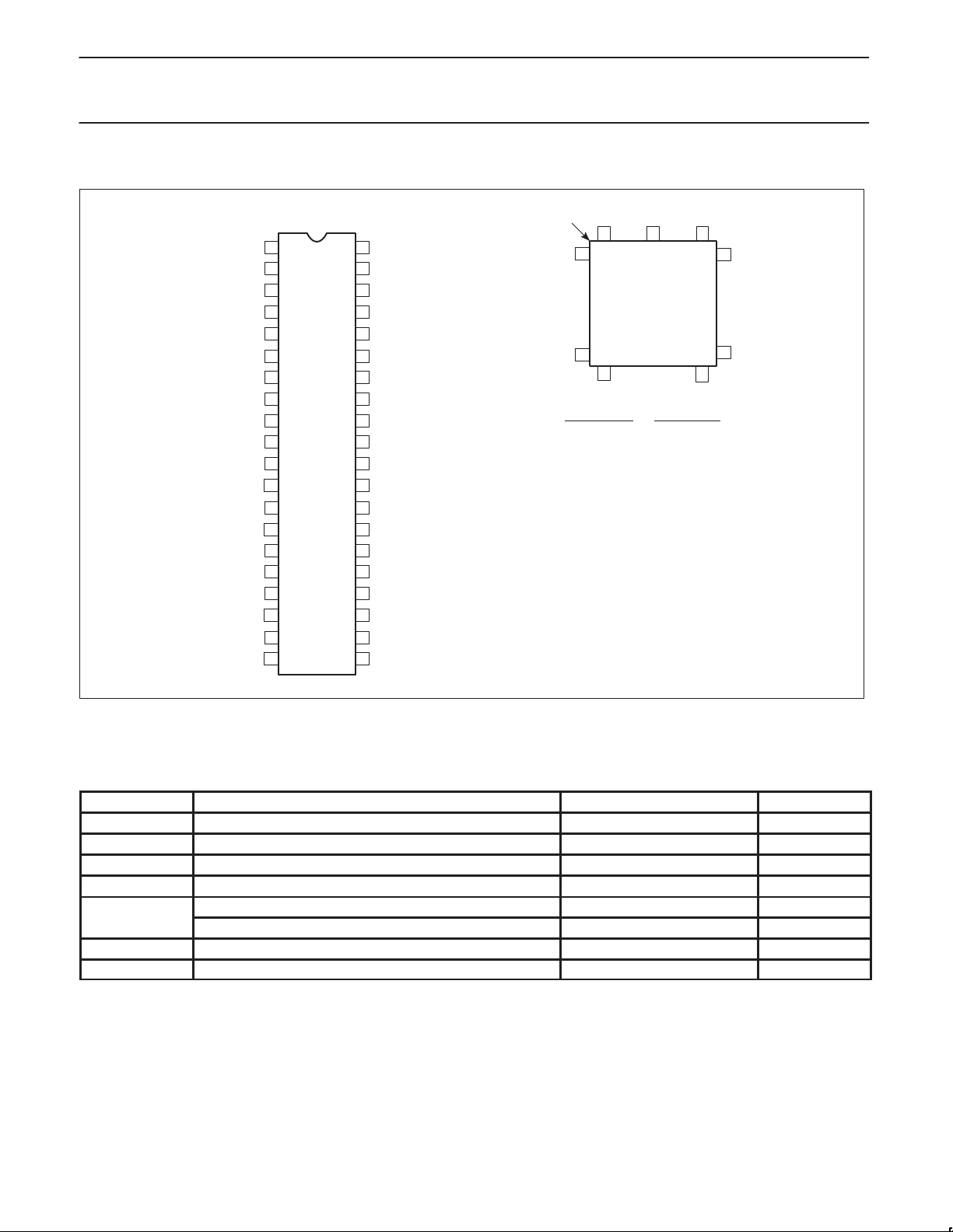
PIN CONFIGURATIONS
INDEX
1
2
IP3
3
A2
4
IP1
5
A3
6
A4
7
IP0
8
R/WN
DTACKN
9
DIP
10
RxDB
11
TxDB
12
OP1
OP3
13
OP5
14
15
OP7
16
D1
17
D3
18
D5
19
D7
GND INTRN
40A1
39
38
37
36
35
34
33
32
31
30
29
28
27
26
25
24
23
22
2120
V
CC
IP4
IP5
IACKN
IP2
CSN
RESETN
X2
X1/CLK
RxDA
TxDA
OP0
OP2
OP4
OP6
D0
D2
D4
D6
CORNER
6
7
17
18
PIN/FUNCTION PIN/FUNCTION
1NC 23NC
2 A1 24 INTRN
3 IP3 25 D6
4A2 26D4
5 IP1 27 D2
6A3 28D0
7 A4 29 OP6
8 IP0 30 OP4
9 R/WN 31 OP2
10 DTACKN 32 OP0
11 RxDB 33 TxDA
12 NC 34 NC
13 TxDB 35 RxDA
14 OP1 36 X1/CLK
15 OP3 37 X2
16 OP5 38 RESETN
17 OP7 39 CSN
18 D1 40 IP2
19 D3 41 IACKN
20 D5 42 IP5
21 D7 43 IP4
22 GND 44 V
1
PLCC
TOP VIEW
40
28
CC
39
29
SD00144
Figure 1. Pin Configurations
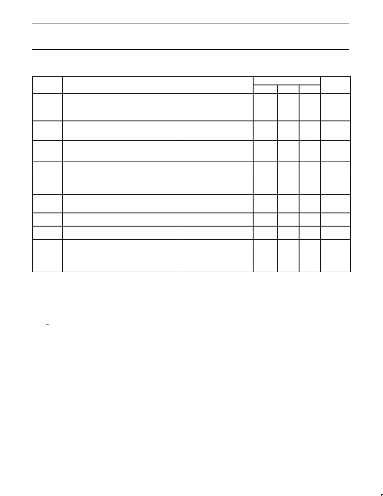
ABSOLUTE MAXIMUM RATINGS
SYMBOL
2
T
V
T
STG
CC
V
A
3
3
S
Operating ambient temperature range Note 4 °C
Storage temperature range -65 to +150 °C
Voltage from VCC to GND -0.5 to +7.0 V
Voltage from any pin to GND -0.5 to VCC +0.5 V
1
PARAMETER RATING UNIT
Package power dissipation DIP40 2.97 W
D
Package power dissipation PLCC44 2.66 W
Derating factor above 25°C DIP40 24 mW/°C
Derating factor above 25°C PLCC44 21 mW/°C
NOTES:
1. Stresses above those listed under Absolute Maximum Ratings may cause permanent damage to the device. This is a stress rating only and
functional operation of the device at these or any other condition above those indicated in the operation section of this specification is not implied.
2. For operating at elevated temperatures, the device must be derated.
3. This product includes circuitry specifically designed for the protection of its internal devices from damaging effects of excessive static
charge. Nonetheless, it is suggested that conventional precautions be taken to avoid applying any voltages larger than the rated maxima.
4. Parameters are valid over specified temperature range.
1998 Sep 04
3
Philips Semiconductors Product specification
SCC68692Dual asynchronous receiver/transmitter (DUART)
BLOCK DIAGRAM
D0–D7
R/WN
DTACKN
CSN
A1–A4
RESETN
INTRN
IACKN
8
BUS BUFFER
OPERATION CONTROL
ADDRESS
4
DECODE
R/W CONTROL
INTERRUPT CONTROL
IMR
ISR
IVR
TIMING
BAUD RATE
GENERATOR
CLOCK
SELECTORS
CONTROL
TIMING
INTERNAL DATABUS
CHANNEL A
TRANSMIT
HOLDING REG
TRANSMIT
SHIFT REGISTER
RECEIVE
HOLDING REG (3)
RECEIVE
SHIFT REGISTER
MRA1, 2
CRA
SRA
CHANNEL B
(AS ABOVE)
INPUT PORT
CHANGE OF
STATE
DETECTORS (4)
IPCR
ACR
TxDA
RxDA
TxDB
RxDB
6
IP0-IP5
X1/CLK
X2
COUNTER/
TIMER
XTAL OSC
CSRA
CSRB
ACR
CTUR
CTLR
Figure 2. Block Diagram
OUTPUT PORT
FUNCTION
SELECT LOGIC
OPCR
OPR
8
OP0-OP7
V
CC
GND
SD00145
1998 Sep 04
4

Philips Semiconductors Product specification
SCC68692Dual asynchronous receiver/transmitter (DUART)
PIN DESCRIPTION
SYMBOL PIN NO. TYPE NAME AND FUNCTION
D0–D7 25,16,24,17
23,18,22,19
CSN 35 I Chip Enable: Active-Low input signal. When Low, data transfers between the CPU and the DUART are
R/WN 8 I Read/Write: A High input indicates a read cycle and a low input indicates a write cycle, when a cycle is
A1–A4 1,2,5,6 I Address Inputs: Select the DUART internal registers and ports for read/write operations.
RESETN 34 I Reset: A Low level clears internal registers (SRA, SRB, IMR, ISR, OPR, OPCR), initializes the IVR to hex
DTACKN 9 O Data Transfer Acknowledge: 3-State active-Low output asserted in write, read, or interrupt cycles to
INTRN 21 O Interrupt Request: Active-Low, open-drain output which signals the CPU that one or more of the eight
IACKN 37 I Interrupt Acknowledge: Active-Low input indicating an interrupt acknowledge cycle. In response, the
X1/CLK 32 I Crystal 1: Crystal connection or an external clock input. A crystal of a clock the appropriate frequency
X2 33 I Crystal 2: Crystal connection. See Figure 9. If a crystal is not used it is best to keep this pin not connected
RxDA 31 I Channel A Receiver Serial Data Input: The least significant bit is received first. “Mark” is High, “space” is Low.
RxDB 10 I Channel B Receive Serial Data Input: The least significant bit is received first. “Mark” is High, “space” is Low.
TxDA 30 O Channel A Transmitter Serial Data Output: The least significant bit is transmitted first. This output is
TxDB 11 O Channel B Transmitter Serial Data Output: The least significant bit is transmitted first. This output is
OP0 29 O Output 0: General purpose output or Channel A request to send (RTSAN, active-Low). Can be
OP1 12 O Output 1: General purpose output or Channel B request to send (RTSBN, active-Low). Can be
OP2 28 O Output 2: General purpose output, or Channel A transmitter 1X or 16X clock output, or Channel A
OP3 13 O Output 3: General purpose output or open-drain, active-Low counter/timer output or Channel B
OP4 27 O Output 4: General purpose output or Channel A open-drain, active-Low, RxRDYAN/FFULLAN output.
OP5 14 O Output 5: General purpose output or Channel B open-drain, active-Low, RxRDYBN/FFULLBN output.
OP6 26 O Output 6: General purpose output or Channel A open-drain, active-Low, TxRDYAN output.
OP7 15 O Output 7: General purpose output or Channel B open-drain, active-Low, TxRDYBN output.
IP0 7 I Input 0: General purpose input or Channel A clear to send active-Low input (CTSAN). Pin has an internal
IP1 4 I Input 1: General purpose input or Channel B clear to send active-Low input (CTSBN). Pin has an internal
IP2 36 I Input 2: General purpose input or Channel B receiver external clock input (RxCB), or counter/timer
IP3 2 I Input 3: General purpose input or Channel A transmitter external clock input (TxCA). When the external
IP4 39 I Input 4: General purpose input or Channel A receiver external clock input (RxCA). When the external
IP5 38 I Input 5: General purpose input or Channel B transmitter external clock input (TxCB). When the external
V
CC
40 I Power Supply: +5V supply input.
GND 20 I Ground
I/O Data Bus: Bidirectional 3-State data bus used to transfer commands, data and status between the
DUART and the CPU. D0 is the least significant bit.
enabled on D0–D7 as controlled by the R/WN and A1–A4 inputs. When CEN is High, the DUART places
the D0–D7 lines in the 3-State condition.
initiated by assertion of the CSN input.
0F, puts OP0–OP7 in the High state, stops the counter/timer, and puts Channels A and B in the inactive
state, with the TxDA and TxDB outputs in the mark (High) state. Resets Test Mode, sets MR pointer to MR1.
indicate proper transfer of data between the CPU and the DUART.
maskable interrupting conditions are true.
DUART will place the interrupt vector on the data bus and will assert DT ACKN if it has an interrupt pending.
(nominally 3.6864 MHz) must be supplied at all times. For crystal connections see Figure 9, Clock Timing.
although it is permissible to ground it.
held in the “mark” condition when the transmitter is disabled, idle or when operating in local loopback
mode. “Mark” is High, “space” is Low.
held in the ‘mark’ condition when the transmitter is disabled, idle, or when operating in local loopback
mode. ‘Mark’ is High, ‘space’ is Low.
deactivated automatically on receive or transmit.
deactivated automatically on receive or transmit.
receiver 1X clock output.
transmitter 1X clock output, or Channel B receiver 1X clock output.
V
pull-up device supplying 1 to 4 A of current.
CC
V
pull-up device supplying 1 to 4 A of current.
CC
external clock input. When external clock is used by the receiver, the received data is sampled on the
rising edge of the clock. Pin has an internal V
pull-up device supplying 1 to 4 A of current.
CC
clock is used by the transmitter, the transmitted data is clocked on the falling edge of the clock. Pin has an
internal V
pull-up device supplying 1 to 4 A of current.
CC
clock is used by the receiver, the received data is sampled on the rising edge of the clock. Pin has an
internal V
pull-up device supplying 1 to 4 A of current.
CC
clock is used by the transmitter, the transmitted data is clocked on the falling edge of the clock. Pin has an
internal V
pull-up device supplying 1 to 4 A of current.
CC
1998 Sep 04
5
Philips Semiconductors Product specification
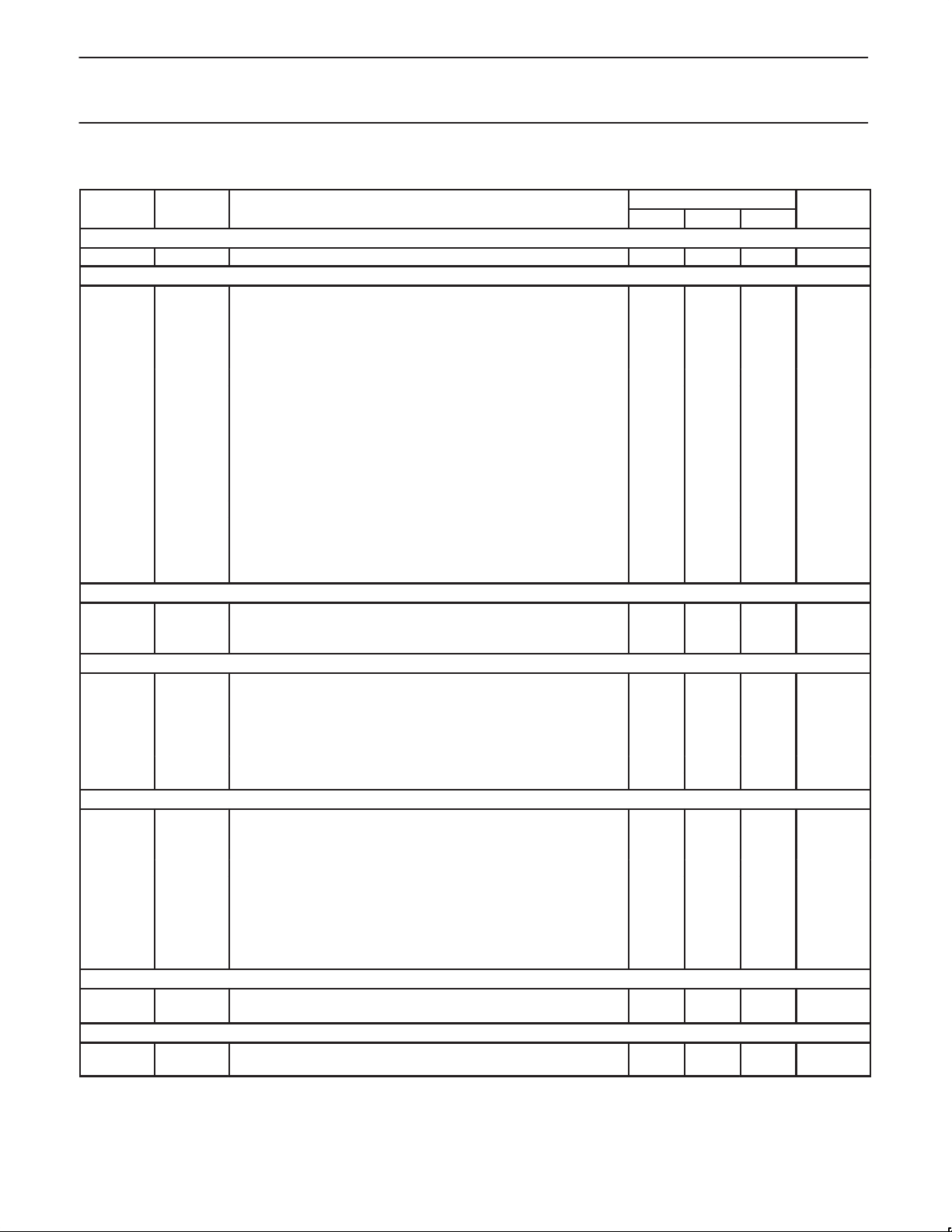
SYMBOL
PARAMETER
TEST CONDITIONS
UNIT
SCC68692Dual asynchronous receiver/transmitter (DUART)
DC ELECTRICAL CHARACTERISTICS
1, 2, 3
LIMITS
Min Typ Max
V
IL
V
IH
V
IH
V
IH
V
OL
V
OH
I
IX1PD
I
ILX1
I
IHX1
I
OHX2
I
OHX2S
I
OLX2
I
OLX2S
I
I
I
OZH
I
OZL
I
ODL
I
ODH
6
7
4
Input low voltage 0.8 V
Input high voltage (except X1/CLK) 2.0 V
Input high voltage (except X1/CLK) 2.5 V
Input high voltage (X1/CLK) 0.8V
Output low voltage
Output high voltage (except OD outputs)
X1/CLK input current – power down
I
= 2.4mA
OL
I
= –400µA
OH
V
= 0 to V
IN
CC
CC
0.4 V
V
CC
–0.5
–10 +10 µA
X1/CLK input low current – operating VIN = 0 –75 0 µA
X1/CLK input high current – operating VIN = V
X2 output high current – operating
X2 output high short circuit current – operating V
X2 output low current – operating V
X2 output low short circuit current – operating and
power down
V
= V
OUT
CC
= 0, X1 = 0 –10 –1 mA
OUT
= 0, X1 = V
OUT
V
= VCC, X1 = V
OUT
CC
, X1 = 0
CC
CC
0 75 µA
0 +75 µA
–75 0 µA
1 10 mA
Input leakage current:
All except input port pins
Input port pins
Output off current high, 3-State data bus VIN = V
VIN = 0 to V
VIN = 0 to V
CC
CC
CC
–10
–20
+10
+10
10 µA
µA
µA
Output off current low , 3-State data bus VIN = 0V –10 µA
Open-drain output low current in off State VIN = 0 –10 10 µA
Open-drain output high current in off State VIN = V
Power supply current
5
CC
µA
V
V
Operating mode TTL input levels 10 mA
I
CC
Power down mode
8
CMOS input levels 10 mA
TTL input levels 3.0 mA
CMOS input levels 2.0 mA
NOTES:
1. Parameters are valid over specified temperature range.
2. All voltage measurements are referenced to ground (GND). For testing, all inputs swing between 0.4V and 2.4V with a transition time of 5ns
maximum. For X1/CLK this swing is between 0.4V and 4.4V . All time measurements are referenced at input voltages of 0.8V and 2.0V and
output voltages of 0.8V and 2.0V , as appropriate.
3. Typical values are at +25°C, typical supply voltages, and typical processing parameters.
4. Test conditions for outputs: C
5. All outputs are disconnected. Inputs are switching between TTL levels of 2.4V and 0.4V or CMOS levels of V
6. T
> 0°C
A
< 0°C
7. T
A
8. See UART application note for power down currents less than 5µA.
= 150pF, except interrupt outputs. Test condition for interrupt outputs: CL = 50pF, R
L
= 2.7kΩ to VCC.
L
–0.2V and VSS + 0.2V .
CC
1998 Sep 04
6
Philips Semiconductors Product specification
SYMBOL
FIGURE
PARAMETER
UNIT
10
SCC68692Dual asynchronous receiver/transmitter (DUART)
AC CHARACTERISTICS
1, 2, 4
LIMITS
Min Typ
3
Max
Reset Timing
t
RES
1 RESET pulse width 200 ns
Bus Timing5
t
AS
t
AH
t
RWS
t
RWH
8
t
CSW
9
t
CSD
t
DD
8
t
DA
8
t
DF
8
t
DI
t
DS
t
DH
t
DAL
t
DCR
t
DCW
t
DAH
I
DAT
7
t
CSC
Port Timing
t
PS
t
PH
t
PD
4,5,6 A1–A4 setup time to CSN Low 10 ns
4,5,6 A1–A4 hold time from CSN Low 100 ns
4,5,6 RWN setup time to CSN High 0 ns
4,5,6 RWN holdup time to CSN High 0 ns
4,5,6 CSN High pulse width 160 ns
4,5,6 CSN or IACKN High from DTACKN Low 20 ns
4,5,6 Data valid from CSN or IACKN Low 175 ns
4 RDN Low to data bus active 15 ns
4,5,6 Data bus floating from CSN or IACKN High 125 ns
4 RDN High to data bus invalid 20 ns
4,5,6 Data setup time to CLK High 100 ns
4,5,6 Data hold time from CSN High 0 ns
4,5,6 DTACKN Low from read data valid 0 ns
4,5,6 DTACKN Low (read cycle) from CLK High 125 ns
4,5,6 DTACKN Low (write cycle) form CLK High 125 ns
4,5,6 DTACKN High from CSN or IACKN High 100 ns
4,5,6 DTACKN High impedance from CSN or IACKN High 125 ns
4,5,6 CSN or IACKN setup time to clock High 90 ns
5
7 Port input setup time to CSN Low 0 ns
7 Port input hold time from CSN High 0 ns
7 Port output valid from CSN High 400 ns
Interrupt Timing
t
IR
6
INTRN (or OP3–OP7 when used as interrupts) negated from:
Read RHR (RxRDY/FFULL interrupt) 300 ns
Write THR (TxRDY interrupt) 300 ns
Reset command (break interrupt) 300 ns
Stop C/T command (counter interrupt) 300 ns
Read IPCR (input port change interrupt) 300 ns
Write IMR (clear of interrupt mask bit) 300 ns
Clock Timing
t
f
t
f
t
f
t
f
CLK
CLK
CTC
CTC
RX
RX
TX
TX
11
9
9
9
7 X1/CLK High or Low time 100 ns
7 X1/CLK frequency 0 3.6864 4 MHz
7 CTCLK (IP2) High or Low time 100 ns
7 CTCLK (IP2) frequency 100 4 MHz
7 RxC High or Low time 220 ns
7
RxC frequency (16X)
(1X)
100
100
2
1
MHz
MHz
7 TxC High or Low time 220 ns
7
TxC frequency (16X)
(1X)
0
0
2
1
MHz
MHz
Transmitter Timing
t
t
TXD
TCS
8 TxD output delay from TxC external clock input on IP pin 350 ns
8 Output delay from TxC low at OP pin to TxD data output 150 ns
Receiver Timing
t
RXS
t
RXH
9 RxD data setup time before RxC high at external clock input on IP pin 240 ns
9 RxD data hold time after RxC high at external clock input on IP pin 200 ns
NOTES:
1. Parameters are valid over specified temperature range.
2. All voltage measurements are referenced to ground (GND). For testing, all inputs swing between 0.4V and 2.4V with a transition time of 5ns
maximum. For X1/CLK this swing is between 0.4V and 4.4V . All time measurements are referenced at input voltages of 0.8V and 2.0V and
output voltages of 0.8V and 2.0V , as appropriate.
3. Typical values are at +25°C, typical supply voltages, and typical processing parameters.
1998 Sep 04
7

Philips Semiconductors Product specification
SCC68692Dual asynchronous receiver/transmitter (DUART)
4. Test conditions for outputs: C
5. This specification will impose maximum 68000 CPU CLK to 6MHz. Higher CPU CLK can be used if repeating bus reads are not performed.
Consecutive write operations to the same command register require at least three edges of the X1 clock between writes.
6. This specification imposes a lower bound on CSN and IACKN Low, guaranteeing that it will be Low for at least 1 CLK period. This requirement is made on CSN only to insure assertion of DTACKN and not to guarantee operation of the part.
7. This specification is made only to insure that DTACKN is asserted with respect to the rising edge of the X1/CLK pin as shown in the timing
diagram, not to guarantee operation of the part. If the setup time is violated, DTACKN may be asserted as shown, or may be asserted one
clock cycle later.
8. Guaranteed by characterization of sample units.
9. Minimum frequencies are not tested but are guaranteed by design.
10.325ns maximum for T
11.Operation to 0MHz is assured by design. Minimum test frequency is 2.0MHz.
12.See UART application note for power down currents less than 5µA.
BLOCK DIAGRAM
The SCC68692 DUART consists of the following eight major
sections: data bus buffer, operation control, interrupt control, timing,
communications Channels A and B, input port and output port.
Refer to the Block Diagram.
Data Bus Buffer
The data bus buffer provides the interface between the external and
internal data buses. It is controlled by the operation control block to
allow read and write operations to take place between the controlling
CPU and the DUART.
Operation Control
The operation control logic receives operation commands from the
CPU and generates appropriate signals to internal sections to
control device operation. It contains address decoding and read and
write circuits to permit communications with the microprocessor via
the data bus buffer. The DTACKN output is asserted during write
and read cycles to indicate to the CPU that data has been latched
on a write cycle, or that valid data is present on the bus on a read
cycle.
Interrupt Control
A single active-Low interrupt output (INTRN) is provided which is
activated upon the occurrence of any of eight internal events.
Associated with the interrupt system are the Interrupt Mask Register
(IMR) and the Interrupt Status Register (ISR), the Auxiliary Control
Register (ACR), and the Interrupt Vector Register (IVR). The IMR
may be programmed to select only certain conditions to cause
INTRN to be asserted. The ISR can be read by the CPU to
determine all currently active interrupting conditions. When IACKN
is asserted, and the DUART has an interrupt pending, the DUART
responds by placing the contents of the IVR register on the data
bus and asserting DTACKN.
Outputs OP3–OP7 can be programmed to provide discrete interrupt
outputs for the transmitter, receivers, and counter/timer.
TIMING CIRCUITS
Crystal Clock
The timing block consists of a crystal oscillator, a baud rate
generator, a programmable 16-bit counter/timer, and four clock
selectors. The crystal oscillator operates directly from a crystal
connected across the X1/CLK and X2 inputs. If an external clock of
the appropriate frequency is available, it may be connected to
X1/CLK. The clock serves as the basic timing reference for the
Baud Rate Generator (BRG), the counter/timer, and other internal
circuits. A clock signal within the limits specified in the
= 150pF, except interrupt outputs. Test condition for interrupt outputs: CL = 50pF, R
L
> 70°C.
A
specifications section of this data sheet must always be supplied to
the DUART.
If an external is used instead of a crystal, X1 should be driven using
a configuration similar to the one in Figure 9.
BRG
The baud rate generator operates from the oscillator or external
clock input and is capable of generating 18 commonly used data
communications baud rates ranging from 50 to 38.4K baud. A
3.6864MHz crystal or external clock must be used to get the
standard baud rate. The clock outputs from the BRG are at 16X the
actual baud rate. The counter/timer can be used as a timer to
produce a 16X clock for any other baud rate by counting down the
crystal clock or an external clock. The four clock selectors allow the
independent selection, for each receiver and transmitter, of any of
these baud rates or external timing signal.
Counter/Timer (C/T)
The counter timer is a 16 bit programmable divider that operates
one of three modes: Counter, T imer or Time Out mode. In all three
modes it uses the 16-bit value loaded to the CTUR and CTLR
registers. (Counter timer upper and lower preset registers).
•In the timer mode it generates a square wave.
•In the counter mode it generates a time delay.
•In the time out mode it monitors the receiver data flow and signals
data flow has paused. In the time out mode the receiver controls
the starting/stopping of the C/T.
The counter operates as a down counter and sets its output bit in
the ISR (Interrupt Status Register) each time it passes through 0.
The output of the counter/timer may be seen on one of the OP pins
or as an Rx or Tx clock.
The Timer/Counter is controlled with six (6) “commands”; Start C/T,
Stop C/T, write C/T, preset registers, read C/T value, set or reset
time out mode.
Please see the detail of the commands under the Counter/Timer
register descriptions.
Communications Channels A and B
Each communications channel of the SCC68692 comprises a
full-duplex asynchronous receiver/transmitter (UART). The
operating frequency for each receiver and transmitter can be
selected independently from the baud rate generator, the counter
timer, or from an external input.
The transmitter accepts parallel data from the CPU, converts it to a
serial bit stream, inserts the appropriate start, stop, and optional
= 2.7kΩ to VCC.
L
1998 Sep 04
8

Philips Semiconductors Product specification
SCC68692Dual asynchronous receiver/transmitter (DUART)
parity bits and outputs a composite serial stream of data on the TxD
output pin. The receiver accepts serial data on the RxD pin,
converts this serial input to parallel format, checks for start bit, stop
bit, parity bit (if any), or break condition and sends an assembled
character to the CPU.
Input Port
The inputs to this unlatched 6-bit port can be read by the CPU by
performing a read operation at address H’D’. A High input results in
a logic 1 while a Low input results in a logic 0. D7 will always be
read as a logic 1 and D6 will reflect the level of IP2. The pins of this
port can also serve as auxiliary inputs to certain portions of the
DUART logic.
Four change-of-state detectors are provided which are associated
with inputs IP3, IP2, IP1 and IP0. A High-to-Low or Low-to-High
transition of these inputs, lasting longer than 25 – 50µs, will set the
corresponding bit in the input port change register. The bits are
cleared when the register is read by the CPU. Any change-of-state
can also be programmed to generate an interrupt to the CPU.
The input port pulse detection circuitry uses a 38.4kHz sampling
clock derived from one of the baud rate generator taps. This results
in a sampling period of slightly more than 25µs (this assumes that
the clock input is 3.6864MHz). The detection circuitry, in order to
guarantee that a true change in level has occurred, requires two
successive samples at the new logic level be observed. As a
consequence, the minimum duration of the signal change is 25µs if
the transition occurs “coincident with the first sample pulse”. The
50µs time refers to the situation in which the change-of-state is “just
missed” and the first change-of-state is not detected until 25µs later.
All the IP pins have a small pull-up device that will source 1 to 4 A
of current from V
connections if they are not used.
V
CC
. These pins do not require pull-up devices or
CC
Output Port
The output port pins may be controlled by the OPR, OPCR, MR and
the CR registers. Via appropriate programming they may be just
another parallel port to external circuits, or they may represent many
internal conditions of the UART. When this 8-bit port is used as a
general purpose output port, the output port pins assume a state
which is the complement of the Output Port Register (OPR).
OPR(n) = 1 results in OP(n) = Low and vice versa. Bits of the OPR
can be individually set and reset. A bit is set by performing a write
operation at address H’E’ with the accompanying data specifying the
bits to be reset (1 = set, 0 = no change). Likewise, a bit is reset by a
write at address H’F’ with the accompanying data specifying the bits
to be reset (1 = reset, 0 = no change).
Outputs can be also be individually assigned specific functions by
appropriate programming of the Channel A mode registers (MR1A,
MR2A), the Channel B mode registers (MR1B, MR2B), and the
Output Port Configuration Register (OPCR).
Output ports are driven high on hardware reset. Please note that
these pins drive both high and low. HOWEVER when they are
programmed to represent interrupt type functions (such as receiver
ready, transmitter ready or counter/timer ready) they will be switched
to an open drain configuration in which case an external pull-up
device would be required.
OPERATION
Transmitter
The SCC68692 is conditioned to transmit data when the transmitter
is enabled through the command register. The SCC68692
indicates to the CPU that it is ready to accept a character by setting
the TxRDY bit in the status register. This condition can be
programmed to generate an interrupt request at OP6 or OP7 and
INTRN. When a character is loaded into the Transmit Holding
Register (THR), the above conditions are negated. Data is
transferred from the holding register to transmit shift register when it
is idle or has completed transmission of the previous character. The
TxRDY conditions are then asserted again which means one full
character time of buffering is provided. Characters cannot be
loaded into the THR while the transmitter is disabled.
The transmitter converts the parallel data from the CPU to a serial
bit stream on the TxD output pin. It automatically sends a start bit
followed by the programmed number of data bits, an optional parity
bit, and the programmed number of stop bits. The least significant
bit is sent first. Following the transmission of the stop bits, if a new
character is not available in the THR, the TxD output remains High
and the TxEMT bit in the Status Register (SR) will be set to 1.
Transmission resumes and the TxEMT bit is cleared when the CPU
loads a new character into the THR. If the transmitter is disabled, it
continues operating until the character currently being transmitted is
completely sent out. The transmitter can be forced to send a
continuous Low condition by issuing a send break command.
The transmitter can be reset through a software command. If it is
reset, operation ceases immediately and the transmitter must be
enabled through the command register before resuming operation. If
CTS operation is enable, the CTSN input must be Low in order for
the character to be transmitted. If it goes High in the middle of a
transmission, the character in the shift register is transmitted and
TxDA then remains in the marking state until CTSN goes Low. The
transmitter can also control the deactivation of the RTSN output. If
programmed, the RTSN output will be reset one bit time after the
character in the transmit shift register and transmit holding register
(if any) are completely transmitted, if the transmitter has been
disabled.
Receiver
The SCC68692 is conditioned to receive data when enabled through
the command register. The receiver looks for a High-to-Low
(mark-to-space) transition of the start bit on the RxD input pin. If a
transition is detected, the state of the RxD pin is sampled each 16X
clock for 7–1/2 clocks (16X clock mode) or at the next rising edge of
the bit time clock (1X clock mode). If RxD is sampled High, the start
bit is invalid and the search for a valid start bit begins again. If RxD
is still Low, a valid start bit is assumed and the receiver continues to
sample the input at one bit time intervals at the theoretical center of
the bit, until the proper number of data bits and parity bit (if any)
have been assembled, and one stop bit has been detected. The
least significant bit is received first. The data is then transferred to
the Receive Holding Register (RHR) and the RxRDY bit in the SR is
set to a 1. This condition can be programmed to generate an
interrupt at OP4 or OP5 and INTRN. If the character length is less
than 8 bits, the most significant unused bits in the RHR are set to
zero.
After the stop bit is detected, the receiver will immediately look for
the next start bit. However, if a non-zero character was received
without a stop bit (framing error) and RxD remains Low for one half
of the bit period after the stop bit was sampled, then the receiver
operates as if a new start bit transition had been detected at that
point (one-half bit time after the stop bit was sampled).
The parity error, framing error, and overrun error (if any) are strobed
into the SR at the received character boundary, before the RxRDY
status bit is set. If a break condition is detected (RxD is Low for the
entire character including the stop bit), a character consisting of all
1998 Sep 04
9
 Loading...