

Philips SCC2698BE1N64, SCC2698AC1A84, SCC2698BC1N64, SCC2698BE1A84 Datasheet

SCC2698B
Enhanced octal universal asynchronous
receiver/transmitter (Octal UART)
Product specification
Supersedes data of 1998 Sep 04
2000 Jan 31
INTEGRATED CIRCUITS
Philips Semiconductors Product specification
SCC2698B
Enhanced octal universal asynchronous
receiver/transmitter (Octal UART)
2
2000 Jan 31 853-1127 23062
DESCRIPTION
The SCC2698B Enhanced Octal Universal Asynchronous
Receiver/Transmitter (Octal UART) is a single chip MOS-LSI
communications device that provides eight full-duplex asynchronous
receiver/transmitter channels in a single package. It is fabricated
with CMOS technology which combines the benefits of high density
and low power consumption.
The operating speed of each receiver and transmitter can be
selected independently as one of 26 fixed baud rates, a 16X clock
derived from a programmable counter/timer, or an external 1X or
16X clock. The baud rate generator and counter/timer can operate
directly from a crystal or from external clock inputs. The ability to
independently program the operating speed of the receiver and
transmitter make the Octal UART particularly attractive for
dual-speed channel applications such as clustered terminal
systems.
The receiver is quadruple buffered to minimize the potential of
receiver overrun or to reduce interrupt overhead in interrupt driven
systems. In addition, a handshaking (RTS/CTS) capability is
provided to disable a remote UART transmitter when the receiver
buffer is full.
The UART provides a power-down mode in which the oscillator is
frozen but the register contents are stored. This results in reduced
power consumption on the order of several magnitudes. The Octal
UART is fully TTL compatible and operates from a single +5V power
supply.
The SCC2698B is an upwardly compatible version of the 2698A
Octal UART. In PLCC packaging, it is enhanced by the addition of
receiver ready or FIFO full status outputs, and transmitter empty
status outputs for each channel on 16 multipurpose I/O pins. The
multipurpose pins of the 2698B RIO pins, thus DMA and modem
control is provided.
FEA TURES
• Eight full-duplex independent asynchronous receiver/transmitters
• Quadruple buffered receiver data register
• Programmable data format:
– 5 to 8 data bits plus parity
– Odd, even, no parity or force parity
– 1, 1.5 or 2 stop bits programmable in 1/16-bit increments
• Baud rate for the receiver and transmitter selectable from:
– 26 fixed rates: 50 to 38.4K baud
Non-standard rates to 115.2K baud
– User-defined rates from the programmable counter/timer
associated with each of four blocks
– External 1x or 16x clock
• Parity, framing, and overrun error detection
• False start bit detection
• Line break detection and generation
• Programmable channel mode
– Normal (full-duplex), automatic echo, local loop back, remote
loopback
• Four multi-function programmable 16-bit counter/timers
• Four interrupt outputs with eight maskable interrupting conditions
for each output
• Receiver ready/FIFO full and transmitter ready status available on
16 multi-function pins in PLCC package
• On-chip crystal oscillator
• TTL compatible
• Single +5V power supply with low power mode
• Eight multi-purpose output pins
• Sixteen multi-purpose I/O pins
• Sixteen multi-purpose Input pins with pull-up resistors
ORDERING INFORMATION
COMMERCIAL INDUSTRIAL
PACKAGES
VCC = +5V +5%, TA = 0°C to +70°C VCC = +5V +5%, TA = –40°C to +85°C
DWG #
84-Pin Plastic Leaded Chip Carrier (PLCC) SCC2698BC1A84 SCC2698BE1A84 SOT189-3
NOTE: Pin Grid Array (PGA) package version is available from Philips Components Military Division.
ABSOLUTE MAXIMUM RATINGS
1
SYMBOL
PARAMETER RATING UNIT
T
A
Operating ambient temperature range
2
Note 4
o
C
T
STG
Storage temperature range –65 to +150
o
C
V
CC
Voltage from V
DD
to GND
3
–0.5 to +7.0 V
V
S
Voltage from any pin to ground
3
–0.5 to V
CC
+0.5 V
P
D
Power dissipation 1 W
NOTES:
1. Stresses above those listed under Absolute Maximum Ratings may cause permanent damage to the device. This is a stress rating only and
functional operation of the device at these or any other condition above those indicated in the operation section of this specification is not
implied.
2. For operating at elevated temperatures, the device must be derated based on +150°C maximum junction temperature.
3. This product includes circuitry specifically designed for the protection of its internal devices from damaging effects of excessive static
charge. Nonetheless, it is suggested that conventional precautions be taken to avoid applying any voltages larger than the rated maxima.
4. Parameters are valid over specified temperature range. See ordering information table for applicable temperature range and operating
supply range.
Philips Semiconductors Product specification
SCC2698B
Enhanced octal universal asynchronous
receiver/transmitter (Octal UART)
2000 Jan 31
3
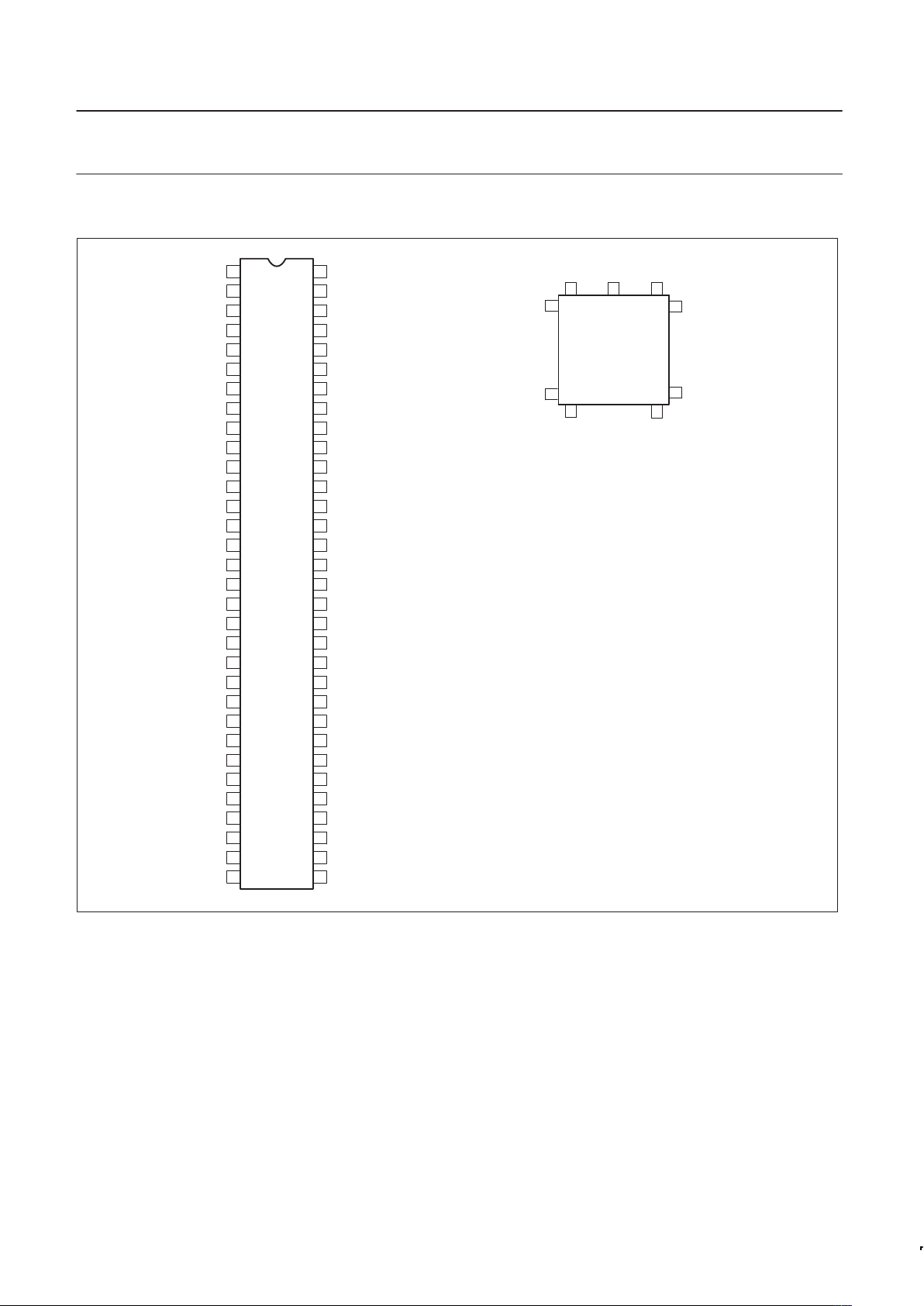
PIN CONFIGURATIONS
1
2
3
4
5
6
7
8
9
10
11
12
13
14
15
16
17
18
19
20
21
22
23
24
25
26
64
63
62
61
60
59
58
57
56
55
54
53
52
51
50
49
48
47
45
45
44
43
42
41
40
39
27
28
29
30
31
32
38
37
36
35
34
33
RxDa
TxDa
RxDc
TxDc
RxDe
MP10h
MP10g
RxDg
TxDe
TxDg
MPOa
MPOc
MPOe
MPOg
GND
MP10f
MP10e
RxDh
RxDf
RxDd
RxDb
TxDh
MPOh
Test input
MPOf
TxDf
MPOd
TxDd
INTRDN
INTRCN
V
CC
MPOb
V
CC
X2
X1/CLK
D0
D1
D2
NC
D3
NC
D4
NC
D5
RESET
D6
D7
CEN
WRN
GND
RDN
A0
A1
A2
A3
A4
A5
MP10a
MP10b
INTRAN
INTRBN
MP10c
MP10d
TxDb
1
74
32
53
75
54
33
12
PLCC
11
Pin Function Pin Function Pin Function
1
2
3
4
5
6
7
8
9
10
11
12
13
14
15
16
17
18
19
20
21
22
23
24
25
26
27
28
TxDa
MPP2g
RxDa
MPP2h
V
CC
X2
X1/CLK
D0
D1
D2
D3
D4
D5
MPI1a
RESET
D6
D7
CEN
WRN
GND
MPI1b
RDN
A0
MPP1a
A1
MPP1b
A2
MPP2a
29
30
31
32
33
34
35
36
37
38
39
40
41
42
43
44
45
46
47
48
49
50
51
52
53
54
55
56
A3
MPP2b
A4
A5
MPI0a
MPI0b
INTRAN
INTRBN
MPI0c
MPI1c
MPI0d
MPI1d
TxDb
MPP1c
MPOb
MPP1d
V
CC
INTRCN
INTRDN
MPP2c
TxDd
MPP2d
MPOd
TxDf
MPOf
MPOh
TxDh
RxDb
57
58
59
60
61
62
63
64
65
66
67
68
69
70
71
72
73
74
75
76
77
78
79
80
81
82
83
84
RxDd
RxDf
RxDh
MPI1e
MPI0e
MPI1f
MPI0f
MPP1e
GND
MPP1f
MPOg
MPP2e
MPOe
MPP2f
MPOc
MPOa
TxDg
TxDe
RxDg
MPI0g
MPI0h
MPI1g
RxDe
MPIh
TxDc
MPP1g
RxDc
MPP1h
SD00184
Figure 1. Pin Configurations
Philips Semiconductors Product specification
SCC2698B
Enhanced octal universal asynchronous
receiver/transmitter (Octal UART)
2000 Jan 31
4
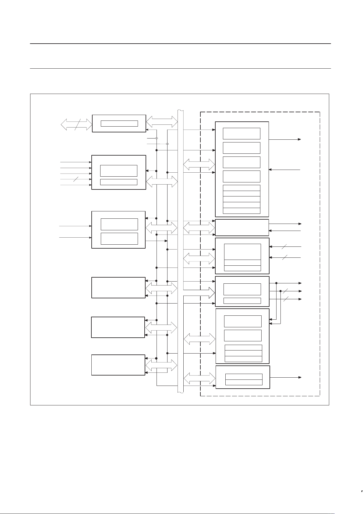
BLOCK DIAGRAM
8
D0–D7
RDN
WRN
CEN
A0–A5
RESET
X1/CLK
X2
6
BUS BUFFER
OPERATION CONTROL
ADDRESS
DECODE
R/W CONTROL
TIMING
CHANNEL A
MR1, 2
CR
SR
INPUT PORT
OUTPUT PORT
OPCR
CSR Rx
CSR Tx
CRYSTAL
OSCILLATOR
POWER-ON
LOGIC
BLOCK B
(SAME AS A)
TRANSMIT HOLD
REGISTER
TRANSMIT SHIFT
REGISTER
RECEIVE HOLD
REGISTER (3)
RECEIVE SHIFT
REGISTER
CHANGE-OF-
STATE
DETECTORS (4)
IPCR
ACR
FUNCTION SELECT
LOGIC
CHANNEL B
(AS ABOVE)
TIMING
CLOCK
SELECTORS
COUNTER/
TIMER
ACR
CTUR
CTLR
INTERRUPT CONTROL
IMR
ISR
BLOCK C
(SAME AS A)
BLOCK D
(SAME AS A)
INTERNAL DATA
BUS
TxDA
RxDA
TxDb
RxDb
MPI0
MPIb
MPP1
MPP2
MPO
INTRAN
BLOCK A
2
2
2
2
TIMING
CONTROL
SD00185
2
Figure 2. Block Diagram

Philips Semiconductors Product specification
SCC2698B
Enhanced octal universal asynchronous
receiver/transmitter (Octal UART)
2000 Jan 31
5
PIN DESCRIPTION
PIN
MNEMONIC
PIN
NO.
TYPE
NAME AND FUNCTION
D0–D7 8–13,
16, 17
I/O Data Bus: Active–High 8-bit bidirectional 3-State data bus. Bit 0 is the LSB and bit 7 is the MSB. All
data, command, and status transfers between the CPU and the Octal UART take place over this bus.
The direction of the transfer is controlled by the WRN and RDN inputs when the CEN input is low.
When the CEN input is High, the data bus is in the 3-State condition.
CEN 18 I Chip Enable: Active-Low input. When Low, data transfers between the CPU and the Octal UART are
enabled on D0–D7 as controlled by the WRN, RDN and A0–A5 inputs. When CEN is High, the Octal
UART is effectively isolated from the data bus and D0–D7 are placed in the 3-State condition.
WRN 19 I Write Strobe: Active-Low input. A Low on this pin while CEN is Low causes the contents of the data
bus to be transferred to the register selected by A0–A5. The transfer occurs on the trailing (rising)
edge of the signal.
RDN 22 I Read Strobe: Active-Low input. A Low on this pin while CEN is Low causes the contents of the
register selected by A0–A5 to be placed on the data bus. The read cycle begins on the leading
(falling) edge of RDN.
A0–A5 23, 25,
27, 29,
31, 32
I Address Inputs: Active-High address inputs to select the Octal UART registers for read/write
operations.
RESET 15 I Reset: Master reset. A High on this pin clears the status register (SR), clears the interrupt mask
register (IMR), clears the interrupt status register (ISR), clears the output port configuration register
(OPCR), places the receiver and transmitter in the inactive state causing the TxD output to go to the
marking (High) state, and stops the counter/timer. Clears power-down mode and interrupts. Clears
Test Modes, sets MR pointer to MR1.
INTRAN–
INTRDN
35, 36,
46, 47
O Interrupt Request: This active-Low open drain output is asserted on occurrence of one or more of
eight maskable interrupting conditions. The CPU can read the interrupt status register to determine
the interrupting condition(s). These pins require a pullup device and may be wire ORed.
X1/CLK 7 I Crystal 1: Crystal or external clock input. When using the crystal oscillator, this pin serves as the
connection for one side of the crystal. If a crystal is not used, an external clock is supplied at this
input. An external clock (or crystal) is required even if the internal baud rate generator is not utilized.
This clock is used to drive the internal baud rate generator, as an optional input to the timer/counter,
and to provide other clocking signals required by the chip.
X2 6 I Crystal 2: Connection for other side of crystal. If an external source is used instead of a crystal, this
connection should be left open (see Figure 9).
RxDa–RxDh 3, 56,
83, 57,
79, 58,
75, 59
I Receiver Serial Data Input: The least significant bit is received first. If external receiver clock is
specified, this input is sampled on the rising edge of the clock. If internal clock is used, the RxD input
is sampled on the rising edge of the RxC1x signal as seen on the MPO pin.
TxDa–TxDh 1, 41,
81, 49,
74, 52,
73, 55
O Transmitter Serial Data Output: The least significant bit is transmitted first. This output is held in the
marking (High) condition when the transmitter is idle or disabled and when the Octal UART is
operating in local loopback mode. If external transmitter is specified, the data is shifted on the falling
edge of the transmitter clock. If internal clock is used, the TxD output changes on the falling edge of
the TxC1x signal as seen on the MPO pin.
MPOa–MPOh 72, 43,
71, 51,
69, 53,
67, 54
O Multi-Purpose Output: Each of the four DUARTS has two MPO pins (one per UART). One of the
following eight functions can be selected for this output pin by programming the OPCR (output port
configuration register). Note that reset conditions MPO pins to RTSN.
RTSN – Request to send active-Low output. This output is asserted and negated via the command
register. By appropriate programming of the mode registers, (MR1[7])=1 R TSN can be programmed to
be automatically reset after the character in the transmitter is completely shifted or when the receiver
FIFO and shift register are full. RTSN is an internal signal which normally represents the condition of
the receiver FIFO not full, i.e., the receiver can request more data to be sent. However, it can also be
controlled by the transmitter empty and the commands 8h and 9h written to the CR (command
register).
C/TO – The counter/timer output.
TxC1X – The 1X clock for the transmitter.
TxC16X – The 16X clock for the transmitter.
RxC1X – The 1X clock for the receiver.
RxC16X – The 16X clock for the receiver.
TxRDY – Transmitter holding register empty signal.
RxRDY/FFULL – Receiver FIFO not empty/full signal.
MPI0a–MPI0h 33, 34,
37, 39,
61, 63,
76, 77
I Multi-Purpose Input 0: This pin (one in each UART) is programmable. Its state can always be read
through the IPCR bit 0, or the IPR bit 0.
CTSN: By programming MR2[4] to a 1, this input controls the clear-to-send function for the
transmitter. It is active low. This pin is provided with a change-of-state detector.
Philips Semiconductors Product specification
SCC2698B
Enhanced octal universal asynchronous
receiver/transmitter (Octal UART)
2000 Jan 31
6
PIN DESCRIPTION (Continued)
PIN
MNEMONIC
PIN
NO.
TYPE
NAME AND FUNCTION
MPI1a–MPI1h 14, 21,
38, 40,
60, 62,
78, 80
I Multi-Purpose Input 1: This pin (one for each UART) is programmable. Its state can always be
determined by reading the IPCR bit 1 or IPR bit 1.
C/TCLK – This input will serve as the external clock for the counter/timer when ACR[5] is set to 0.
This occurs only for channels a, c, e, and g since there is one counter/timer for each DUART block.
This pin is provided with a change-of-state detector.
MPP1a–MPP1h 24, 26,
42, 44,
64, 66,
82, 84
I/O Multi-Purpose Pin 1: This pin (one for each UART) is programmed to be an input or an output
according to the state of OPCR[7]. (0 = input, 1 = output). The state of the multi-purpose pin can
always be determined by reading the IPR. When programmed as an input, it will be the transmitter
clock (TxCLK). It will be 1x or 16x according to the clock select registers (CSR[3.0]). When
programmed as an output, it will be the status register TxRDY bit. These pins have a small pull-up
device.
MPP2a–MPP2h 28, 30,
48, 50,
68, 70,
2, 4
I/O Multi-Purpose Pin 2: This pin (one for each UART) is programmed to be an input or an output
according to the state of OPCR[7]. (0 = input, 1 = output). The state of the multi-purpose pin can
always be determined by reading the IPR. When programmed as an input, it will be the receiver clock
(RxCLK). It will be 1x or 16x according to the clock select registers (CSR[7:4). When programmed as
an output, it will be the ISR status register RxRDY/FIFO full bit. These pins have a small pull-up
device.
Test Input – I T est Input: This pin is used as an input for test purposes at the factory while in test mode. This pin
can be treated as ‘N/C’ by the user. It can be tied high, or left open.
V
CC
5, 45 I Power Supply: +5V supply input.
GND 20, 65 I Ground
BLOCK DIAGRAM
As shown in the block diagram, the Octal UART consists of: data
bus buffer, interrupt control, operation control, timing, and eight
receiver and transmitter channels. The eight channels are divided
into four different blocks, each block independent of each other (see
Figure 3). Figure 2 represents the DUART block.
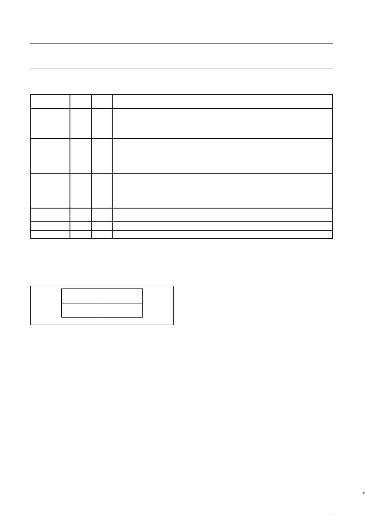
BLOCK A
CHANNELS a, b
BLOCK C
CHANNELS e, f
BLOCK D
CHANNELS g, h
BLOCK B
CHANNELS c, d
SD00186
Figure 3. Channel Architecture
Channel Blocks
There are four blocks (Figure 3), each containing two sets of
receiver/transmitters. In the following discussion, the description
applies to Block A which contains channels a and b. However, the
same information applies to all channel blocks.
Data Bus Buffer
The data bus buffer provides the interface between the external and
internal data buses. It is controlled by the operation control block to
allow read and write operations to take place between the controlling
CPU and the Octal UART.
Interrupt Control
A single interrupt output per DUART (INTRN) is provided which is
asserted on occurrence of any of the following internal events:
–Transmit holding register ready for each channel
–Receive holding register ready or FIFO full for each channel
–Change in break received status for each channel
–Counter reached terminal count
–Change in MPI input
Associated with the interrupt system are the interrupt mask register
(IMR) and the interrupt status register (ISR). The IMR can be
programmed to select only certain conditions, of the above, to cause
INTRN to be asserted. The ISR can be read by the CPU to
determine all currently active interrupting conditions. However, the
bits of the ISR are not masked by the IMR. The transmitter ready
status and the receiver ready or FIFO full status can be provided on
MPP1a, MPP1b, MPP2a, and MPP2b by setting OPCR[7]. these
outputs are not masked by IMR.
Operation Control
The operation control logic receives operation commands from the
CPU and generates appropriate signals to internal sections to
control device operation. It contains address decoding and read and
write circuits to permit communications with the microprocessor via
the data bus buffer. The functions performed by the CPU read and
write operations are shown in Table 1.
Mode registers 1 and 2 are accessed via an auxiliary pointer. The
pointer is set to MR1 by RESET or by issuing a reset pointer
command via the command register . Any read or write of the mode
register while the pointer is at MR1 switches the pointer to MR2 after
the read or write. The pointer then remains at MR2 so that
subsequent accesses are to MR2. To access MR1, the command
0001 of the command register must be executed.
Timing Circuits
The timing block consists of a crystal oscillator, a baud rate
generator, a programmable 16-bit counter/timer for each block, and
two clock selectors.
Crystal Clock
The crystal oscillator operates directly from a 3.6864MHz crystal
connected across the X1/ CLK and X2 inputs with a minimum of
external components. If an external clock of the appropriate
frequency is available, it may be connected to X1/CLK. If an external

Philips Semiconductors Product specification
SCC2698B
Enhanced octal universal asynchronous
receiver/transmitter (Octal UART)
2000 Jan 31
7
clock is used instead of a crystal, X1 must be driven and X2 left
floating as shown in Figure 9. The clock serves as the basic timing
reference for the baud rate generator (BRG), the counter/timer, and
other internal circuits. A clock frequency, within the limits specified in
the electrical specifications, must be supplied even if the internal
BRG is not used.
Table 1. Register Addressing
Units A and B Units E and F
A5 A4 A3 A2 A1 A0 READ (RDN=0)
WRITE
(WRN=0)
A5 A4 A3 A2 A1 A0 READ (RDN=0)
WRITE
(WRN=0)
0 0 0 0 0 0 MR1a, MR2a MR1a, MR2a 1 0 0 0 0 0 MR1e, MR2e MR1e, MR2e
0 0 0 0 0 1 SRa CSRa 1 0 0 0 0 1 SRe CSRe
0 0 0 0 1 0 BRG Test
2
CRa 1 0 0 0 1 0 Reserved
1
CRe
0 0 0 0 1 1 RHRa THRa 1 0 0 0 1 1 RHRe THRe
0 0 0 1 0 0 IPCRA ACRA 1 0 0 1 0 0 IPCRC ACRC
0 0 0 1 0 1 ISRA IMRA 1 0 0 1 0 1 ISRC IMRC
0 0 0 1 1 0 CTUA CTPUA 1 0 0 1 1 0 CTUC CTPUC
0 0 0 1 1 1 CTLA CTPLA 1 0 0 1 1 1 CTLC CTPLC
0 0 1 0 0 0 MR1b, MR2b MR1b, MR2b 1 0 1 0 0 0 MR1f, MR2f MR1f, MR2f
0 0 1 0 0 1 SRb CSRb 1 0 1 0 0 1 SRf CSRf
0 0 1 0 1 0 1X/16X Test
2
CRb 1 0 1 0 1 0 Reserved
1
CRf
0 0 1 0 1 1 RHRb THRb 1 0 1 0 1 1 RHRf THRf
0 0 1 1 0 0 Reserved
1
Reserved
1
1 0 1 1 0 0 Reserved
1
Reserved
1
0 0 1 1 0 1 Input port A OPCRA 1 0 1 1 0 1 Input port C OPCRC
0 0 1 1 1 0 Start C/T A Reserved
1
1 0 1 1 1 0 Start C/T C Reserved
1
0 0 1 1 1 1 Stop C/T A Reserved
1
1 0 1 1 1 1 Stop C/T C Reserved
1
Units C and D Units G and H
0 1 0 0 0 0 MR1c, MR2c MR1c, MR2c 1 1 0 0 0 0 MR1g, MR2g MR1g, MR2g
0 1 0 0 0 1 SRc CSRc 1 1 0 0 0 1 SRg CSRg
0 1 0 0 1 0 Reserved
1
CRc 1 1 0 0 1 0 Reserved
1
CRg
0 1 0 0 1 1 RHRc THRc 1 1 0 0 1 1 RHRg THRg
0 1 0 1 0 0 IPCRB ACRB 1 1 0 1 0 0 IPCRD ACRD
0 1 0 1 0 1 ISRB IMRB 1 1 0 1 0 1 ISRD IMRD
0 1 0 1 1 0 CTUB CTPUB 1 1 0 1 1 0 CTUD CTPUD
0 1 0 1 1 1 CTLB CTPLB 1 1 0 1 1 1 CTLD CTPLD
0 1 1 0 0 0 MR1d, MR2d MR1d, MR2d 1 1 1 0 0 0 MR1h, MR2h MR1h, MR2h
0 1 1 0 0 1 SRd CSRd 1 1 1 0 0 1 SRh CSRh
0 1 1 0 1 0 Reserved
1
CRd 1 1 1 0 1 0 Reserved
1
CRh
0 1 1 0 1 1 RHRd THRd 1 1 1 0 1 1 RHRh THRh
0 1 1 1 0 0 Reserved
1
Reserved
1
1 1 1 1 0 0 Reserved
1
Reserved
1
0 1 1 1 0 1 Input port B OPCRB 1 1 1 1 0 1 Input port D OPCRD
0 1 1 1 1 0 Start C/T B Reserved
1
1 1 1 1 1 0 Start C/T D Reserved
1
0 1 1 1 1 1 Stop C/T B Reserved
1
1 1 1 1 1 1 Stop C/T D Reserved
1
NOTE:
1. Reserved registers should never be read during normal operation since they are reserved for internal diagnostics.
ACR = Auxiliary control register SR = Status Register
CR = Command register THR = Tx holding register
CSR = Clock select register RHR = Rx holding register
CTL = Counter/timer lower IPCR = Input port change register
CTPL = Counter/timer preset lower register ISR = Interrupt status register
CTU = Counter/timer upper IMR = Interrupt mask register
CTPU = Counter/timer preset upper register OPCR= Output port configuration register
MR = Mode register
2. See T able 5 for BRG Test frequencies in this data sheet, and
“Extended baud rates for SCN2681, SCN68681, SCC2691, SCC2692, SCC68681
and SCC2698B”
Philips Semiconductors ICs for Data Communications, IC-19, 1994.
BRG
The baud rate generator operates from the oscillator or external
clock input and is capable of generating 26 commonly used data
communications baud rates ranging from 50 to 115.2K baud.
Thirteen of these are available simultaneously for use by the
receiver and transmitter. Eight are fixed, and one of two sets of five
can be selected by programming ACR[7]. The clock outputs from
the BRG are at 16X the actual baud rate. The counter/timer can be
used as a timer to produce a 16X clock for any other baud rate by
counting down the crystal clock or an external clock. The clock
selectors allow the independent selection, by the receiver and
transmitter, of any of these baud rates or an external timing signal.
Counter–Timer
The four Counter/Timers are programmable 16 bit dividers that are
used for generating miscellaneous clocks or generating timeout

Philips Semiconductors Product specification
SCC2698B
Enhanced octal universal asynchronous
receiver/transmitter (Octal UART)
2000 Jan 31
8
periods. These clocks may be used by any or all of the receivers
and transmitters in the OCTAR T or may be directed to an I/O pin for
miscellaneous use.
Counter/Timer programming
The counter timer is a 16–bit programmable divider that operates in
one of three modes: counter, timer, and time out.
• Timer mode generates a square wave.
• Counter mode generates a time delay.
• Time out mode counts time between received characters.
The C/T uses the numbers loaded into the Counter/Timer Lower
Register (CTPL) and the Counter/Timer Upper Register (CTPU) as
its divisor. The counter timer is controlled with six commands:
Start/Stop C/T, Read/Write Counter/Timer lower register and
Read/Write Counter/Timer upper register. These commands have
slight differences depending on the mode of operation. Please see
the detail of the commands under the CTPL/CTPU register
descriptions.
Baud Rate Generation
When these timers are selected as baud rates for receiver or transmitter via the Clock Select register their output will be configured as
a 16x clock. Therefore one needs to program the timers to generate
a clock 16 times faster than the data rate. The formula for calculating ’n’, the number loaded to the CTPU and CTPL registers, based
on a particular input clock frequency is shown below.
For the timer mode the formula is as follows:
n=
Clockinputfrequency
2 16 Baudratedesired
NOTE: ‘n’ may not assume values of 0 and 1.
The frequency generated from the above formula will be at a rate 16
times faster than the desired baud rate. The transmitter and receiver state machines include divide by 16 circuits, which provide the
final frequency and provide various timing edges used in the qualifying the serial data bit stream. Often this division will result in a non–
integer value: 26.3 for example. One may only program integer
numbers to a digital divider. There for 26 would be chosen. If 26.7
were the result of the division then 27 would be chosen. This gives
a baud rate error of 0.3/26.3 or 0.3/26.7 that yields a percentage
error of 1.14% or 1.12% respectively, well within the ability of the
asynchronous mode of operation. Higher input frequency to the
counter reduces the error effect of the fractional division
One should be cautious about the assumed benign effects of small
errors since the other receiver or transmitter with which one is communicating may also have a small error in the precise baud rate. In
a ”clean” communications environment using one start bit, eight data
bits and one stop bit the total difference allowed between the transmitter and receiver frequency is approximately 4.6%. Less than
eight data bits will increase this percentage.
Receiver and Transmitter
The Octal UART has eight full-duplex asynchronous
receiver/transmitters. The operating frequency for the receiver and
transmitter can be selected independently from the baud rate
generator, the counter/timer, or from an external input.
Registers associated with the communications channel are the
mode registers (MR1 and MR2), the clock select register (CSR), the
command register (CR), the status register (SR), the transmit
holding register (THR), and the receive holding register (RHR).
Transmitter
The SCC2698 is conditioned to transmit data when the transmitter is
enabled through the command register. The SCC2698 indicates to
the CPU that it is ready to accept a character by setting the TxRDY
bit in the status register. This condition can be programmed to generate an interrupt request at MPO or MPP1 and INTRN. When the
transmitter is initially enabled the TxRDY and TxEMT bits will be set
in the status register. When a character is loaded to the transmit
FIFO the TxEMT bit will be reset. The TxEMT will not set until: 1)
the transmit FIFO is empty and the transmit shift register has finished transmitting the stop bit of the last character written to the
transmit FIFO, or 2) the transmitter is disabled and then re–enabled.
The TxRDY bit is set whenever the transmitter is enabled and the
TxFIFO is not full. Data is transferred from the holding register to
transmit shift register when it is idle or has completed transmission
of the previous character. Characters cannot be loaded into the
TxFIFO while the transmitter is disabled.
The transmitter converts the parallel data from the CPU to a serial
bit stream on the TxD output pin. It automatically sends a start bit
followed by the programmed number of data bits, an optional parity
bit, and the programmed number of stop bits. The least significant
bit is sent first. Following the transmission of the stop bits, if a new
character is not available in the TxFIFO, the TxD output remains
High and the TxEMT bit in the Status Register (SR) will be set to 1.
Transmission resumes and the TxEMT bit is cleared when the CPU
loads a new character into the TxFIFO.
If the transmitter is disabled, it continues operating until the character currently being transmitted and any characters in the TxFIFO
including parity and stop bit(s) have been completed.
The transmitter can be forced to send a continuous Low condition by
issuing a send break command from the command register. The
transmitter output is returned to the normal high with a stop break
command.
The transmitter can be reset through a software command. If it is
reset, operation ceases immediately and the transmitter must be
enabled through the command register before resuming operation.
If CTS option is enabled (MR2[4] = 1), the CTSN input at MPI0 must
be Low in order for the character to be transmitted. The transmitter
will check the state of the CTS input at the beginning of each character transmitted. If it is found to be High, the transmitter will delay
the transmission of any following characters until the CTS has returned to the low state. CTS going high during the serialization of a
character will not affect that character.
Transmitter “RS485 turnaround”
The transmitter can also control the RTSN outputs, MPO via
MR2[5]. When this mode of operation is set, the meaning of the
MPO signal will usually be ‘end of message’. See description of the
MR2[5] bit for more detail.
Transmitter Flow control
The transmitter may be controlled by the CTSN input when enabled
by MR2(4). The CTSN input would be connected to RTSN output of
the receiver to which it is communicating. See further description in
the MR 1 and MR2 register descriptions.
Receiver
The SCC2698 is conditioned to receive data when enabled through
the command register. The receiver looks for a High–to–Low
(mark–to–space) transition of the start bit on the RxD input pin. If a
transition is detected, the state of the RxD pin is sampled each 16X
clock for 7–1/2 clocks (16X clock mode) or at the next rising edge of

Philips Semiconductors Product specification
SCC2698B
Enhanced octal universal asynchronous
receiver/transmitter (Octal UART)
2000 Jan 31
9
the bit time clock (1X clock mode). If RxD is sampled high, the start
bit is invalid and the search for a valid start bit begins again. If RxD
is still low, a valid start bit is assumed. The receiver then continues
to sample the input at one–bit time intervals at the theoretical center
of the bit. When the proper number of data bits and parity bit (if any)
have been assembled, with one half–stop bit the character will be
considered complete. The least significant bit is received first. The
data is then transferred to the Receive FIFO and the RxRDY bit in
the SR is set to a 1. This condition can be programmed to generate
an interrupt at MPO or MPP2 and INTRN. If the character length is
less than 8 bits, the most significant unused bits in the RxFIFO are
set to zero.
Receiver FIFO
The RxFIFO consists of a First–In–First–Out (FIFO) stack with a
capacity of 3 characters. Data is loaded from the receive shift register into the topmost empty position of the FIFO. The RxRDY bit in
the status register is set whenever one or more characters are available to be read, and a FFULL status bit is set if all three (3) stack
positions are filled with data. Either of these bits can be selected to
cause an interrupt. A read of the RxFIFO outputs the data at the top
of the FIFO. After the read cycle, the data FIFO and its associated
status bits (see below) are ‘popped’ thus emptying a FIFO position
for new data.
Receiver Status Bits
There are five (5) status bits that are evaluated with each byte (or
character) received: received break, framing error, parity error, overrun error, and change of break. The first three are appended to
each byte and stored in the RxFIFO. The last two are not necessarily related to the byte being received or a byte that is in the RxFIFO.
They are however developed by the receiver state machine.
The received break, framing error, parity error and overrun error (if
any) are strobed into the RxFIFO at the received character boundary, before the RxRDY status bit is set. For character mode (see
below) status reporting the SR (Status Register) indicates the condition of these bits for the character that is the next to be read from the
FIFO
The ”received break” will always be associated with a zero byte in
the RxFIFO. It means that zero character was a break character
and not a zero data byte. The reception of a break condition will
always set the ”change of break” (see below) status bit in the Interrupt Status Register (ISR). The Change of break condition is reset
by a reset error status command in the command register
Break Detection
If a break condition is detected (RxD is Low for the entire character
including the stop bit), a character consisting of all zeros will be
loaded into the RxFIFO and the received break bit in the SR is set to
1. The change of break bit also sets in the ISR The RxD input must
return to high for two (2) clock edges of the X1 crystal clock for the
receiver to recognize the end of the break condition and begin the
search for a start bit.
This will usually require a high time of one X1 clock period or 3 X1
edges since the clock of the controller is not synchronous to the X1
clock.
Framing Error
A framing error occurs when a non–zero character whose parity bit
(if used) and stop; bit are zero. If RxD remains low for one half of
the bit period after the stop bit was sampled, then the receiver operates as if the start bit of the next character had been detected.
The parity error indicates that the receiver–generated parity was not
the same as that sent by the transmitter.
The framing, parity and received break status bits are reset when
the associated data byte is read from the RxFIFO since these “error”
conditions are attached to the byte that has the error
Overrun Error
The overrun error occurs when the RxFIFO is full, the receiver shift
register is full, and another start bit is detected. At this moment the
receiver has 4 valid characters and the start bit of the 5
th
has been
seen. At this point the host has approximately 6/16–bit time to read
a byte from the RxFIFO or the overrun condition will be set. The 5
th
character then overruns the 4th and the 6th the 5th and so on until
an open position in the RxFIFO is seen. (“seen” meaning at least
one byte was read from the RxFIFO.)
Overrun is cleared by a use of the “error reset” command in the
command register.
The fundamental meaning of the overrun is that data has been lost.
Data in the RxFIFO remains valid. The receiver will begin placing
characters in the RxFIFO as soon as a position becomes vacant.
Note: Precaution must be taken when reading an overrun FIFO.
There will be 3 valid characters in the receiver FIFO. There will be
one character in the receiver shift register. However it will NOT be
known if more than one “over–running” character has been received
since the overrun bit was set. The 4
th
character is received and
read as valid but it will not be known how many characters were lost
between the two characters of the 3
rd
and 4th reads of the RxFIFO
The ”Change of break” means that either a break has been detected
or that the break condition has been cleared. This bit is available in
the ISR. The break change bit being set in the ISR and the received
break bit being set in the SR will signal the beginning of a break. At
the termination of the break condition only the change of break in
the ISR will be set. After the break condition is detected the termination of the break will only be recognized when the RxD input
has returned to the high state for two successive edges of the 1x
clock; 1/2 to 1 bit time (see above).
The receiver is disabled by reset or via CR commands. A disabled
receiver will not interrupt the host CPU under any circumstance in
the normal mode of operation. If the receiver is in the multi–drop or
special mode, it will be partially enabled and thus may cause an
interrupt. Refer to section on Wake–Up and the register description
for MR1 for more information.
Receiver Status Modes (block and character)
In addition to the data word, three status bits (parity error, framing
error, and received break) are also appended to each data character
in the FIFO (overrun is not). Status can be provided in two ways, as
programmed by the error mode control bit in the mode register. In
the ‘character’ mode, status is provided on a character–by–character basis; the status applies only to the character at the top of the
FIFO. In the ‘block’ mode, the status provided in the SR for these
three bits is the logical–OR of the status for all characters coming to
the top of the FIFO since the last ‘reset error’ command was issued.
In either mode reading the SR does not affect the FIFO. The FIFO
is ‘popped’ only when the RxFIFO is read. Therefore the status
register should be read prior to reading the FIFO.
Receiver Flow Control
The receiver can control the deactivation of RTS. If programmed to
operate in this mode, the RTSN output will be negated when a valid
start bit was received and the FIFO is full. When a FIFO position
becomes available, the RTSN output will be re–asserted automati-
cally. This feature can be used to prevent an overrun, in the receiver, by connecting the RTSN output to the CTSN input of the
transmitting device.
 Loading...