

Page 1
Philips Healthcare
SERVICE BULLETIN
Issued by
T
ITLE: SB86201431B - Expression (DCU) Motherboard Upgrade
APPLIES TO:
Geography :
:
PM-A Jason Pereira
SB Ref No.
Date : 4/13/2012
:
SB86201431B
INFORMATION ONLY — NO ACTION REQUIRED
Worldwide
Commercial (Sales) Product
Number
Range of Serial Numbers
PMS Number:
865214
ALL
Part Number:
865214
The only change from Rev. A to Rev. B is the correction of a part number
and location of an arrow in section C, slides 13 & 14. There is no change
to the procedure.
SERVICE BULLETIN INFORMATION:
This document is to provide instruction for a Geode Motherboard Upgrade on an Expression DCU.
This upgrade will be necessary whenever a 453564174041 Motherboard (Old style) has failed and
needs to be replaced. The 453564263971 motherboard (New style) is the replacement for the
453564174041 Motherboard (Old style).
Note: It may be advantageous in some circumstances to simply order the exchange
“DCU” instead of replacing the motherboard.
The below parts are necessary to perform this upgrade.
SERVICE BULLETIN SB86201431B Page 1 of 10
Page 2
(1) 453564263971 PCA Geode based MRI Motherboard
(1) 453564253291 STAMPING BRKT, GEODE MOTHERBOARD, DCU
(1) 453564155941 SCR, #6-32 X 3/8 LG, PHMS-XR, SS, NM, PL
PROCEDURE:
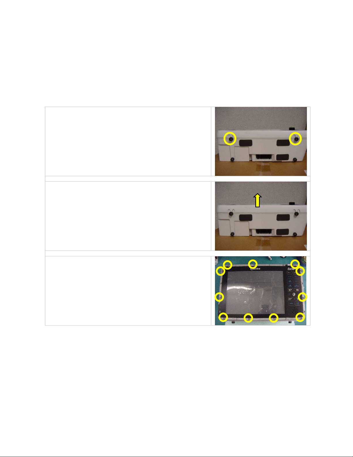
A. Prepare Unit for Upgrade
1. Remove 453564060621 front feet by removing
453564155941 Screws and 453564133441 washers.
Set aside for re-use.
2. Lift, remove and set aside 453564107941 Bezel for
re-use
3. Remove 11 ea 453564116751 screws and set aside
for re-use
SERVICE BULLETIN SB86201431B Page 2 of 10
Page 3

B. Remove 453564174041 Motherboard
1. Unplug 14 ea cables from Motherboard as
shown
2. Remove 7 ea 453564155941 Screws from
motherboard
3. Set aside screws for re-use
4. Remove 1 ea 453564099571 Screw from
453564137681 Battery Holder
5. Set aside screw and holder for re-use
6. Remove 453564105841 cable from backside of
Motherboard
7. Set aside Mother and Daughter Boards
8. Boards will not be re-used
SERVICE BULLETIN SB86201431B Page 3 of 10
Page 4

9. Unplug 453564105841 Cable from Radio
10. Set aside cable for re-use
11. Remove 4 ea 453564155941 Screws that retain
453564155441 Mounting Plate to Casting.
12. Set aside screws for re-use
13. Mounting Plate will not be re-used
SERVICE BULLETIN SB86201431B Page 4 of 10
Page 5

C. Install New Geode Motherboard
1. Assemble 453564253291 Adapter Bracket to
453564263971 Motherboard re-using 6ea
453564155941 Screws
Use 453564138561 Blue Loctite on screw threads
2. Orient and connect re-used 453564105841 Cable to
bottom side of Motherboard
3. Assemble Motherboard with Bracket to casting, re-
using 4 ea 453564109901 Screws.
Use 453564138561 Blue Loctite on screw threads
SERVICE BULLETIN SB86201431B Page 5 of 10
Page 6

4. Orient and connect previously assembled
453564105841 Cable to Radio.
Observe colored edge stripe on cable
5. Assemble re-used 453564137681 to PCA re-using 1 ea
453564099571 Screw.
Use 453564138561 Blue Loctite on screw threads
6. Assemble 1 ea re-used and 1 ea new 453564155941
Screw to Motherboard
Use 453564138561 Blue Loctite on screw threads
7. Orient and assemble already-connected 453564106041
Cable to 453564263971 (J1).
Observe Blue Stripe Orientation
8. Connect BLUE section of already-assembled AC542A
Comm Cable to 453564263971 (J15)
SERVICE BULLETIN SB86201431B Page 6 of 10
Page 7

9. Connect already-assembled 453564105741 Printer
Cable to 453564263971 (J5)
10. Connect already-assembled AC526 cable to
453564263971 (J7) connector
11. Connect already-assembled cable from the
453564155711 Display to 453564263971 (J2)
connector
12. Connect already-assembled 453564106821 Cable to
453564263971 (J45) connector
13. Connect previously assembled AC528A Cable to
453564263971 (J9)
SERVICE BULLETIN SB86201431B Page 7 of 10
Page 8

14. Connect already-assembled 453564137211 Data
Cable to 453564263971 (J10)
15. Connect already-assembled 453564060661 VGA
Cable to 453564263971 (J3)
16. Connect GRN section of already-assembled AC542A
Comm Cable to 453564263971 (J28)
17. Connect previously assembled 453564060641 USB
Cable to 453564263971 (J44)
18. Connect previously assembled AC540A Keyboard
Cable to 453564263971 (J11)
SERVICE BULLETIN SB86201431B Page 8 of 10
Page 9

D. Final Assembly
Known Pinch Point !!
1. With DCU laying on it’s back, fit front housing to
rear housing, make sure that RF gasket is in the
channel, and that all cables are tucked in and clear of
pinch points before adding screws
2. Assemble two halves with 11 ea re-used
453564116751 Screws
Use 453564138561 Blue Loctite on screw
threads
4. Assemble re-used 453564107941 Bezel
5. Assemble 2 ea re-used 453564060621 front feet using
2 ea re-used 453564155941 Screws and
453564133441 washers.
Use 453564138561 Blue Loctite on screw
threads
SERVICE BULLETIN SB86201431B Page 9 of 10
Page 10

D. Software compatibility check
Confirm monitor is loaded with version 4 (Or higher) of Expression software (ET53445). If the
unit contains <4 software, please load the newest version of Expression software available in
Incenter.
Note: The new motherboard is only compatible with version 4 or higher.
RELATED DOCUMENTS:
Please reference the Expression Service Guide as needed (It can be found in Incenter)
EC NUMBER: 2975-2012-04-02939
SERVICE BULLETIN SB86201431B Page 10 of 10
 Loading...