

Philips SAVVY VOGUE DUAL BAND Service Manual
Philips Consumer Communications
PHILIPS
CUSTOMER SERVICES
Author : Fabrice Tant
Approval : Jean Pierre Hollande
Operational Manager
SERVICE REPAIR SUPPORT
PROCEDURE
PCC/VY/691/E/TCD188LVL2/0026/TF/MLD
Creation
Date : 26/06/2000
Page : 1 of 30
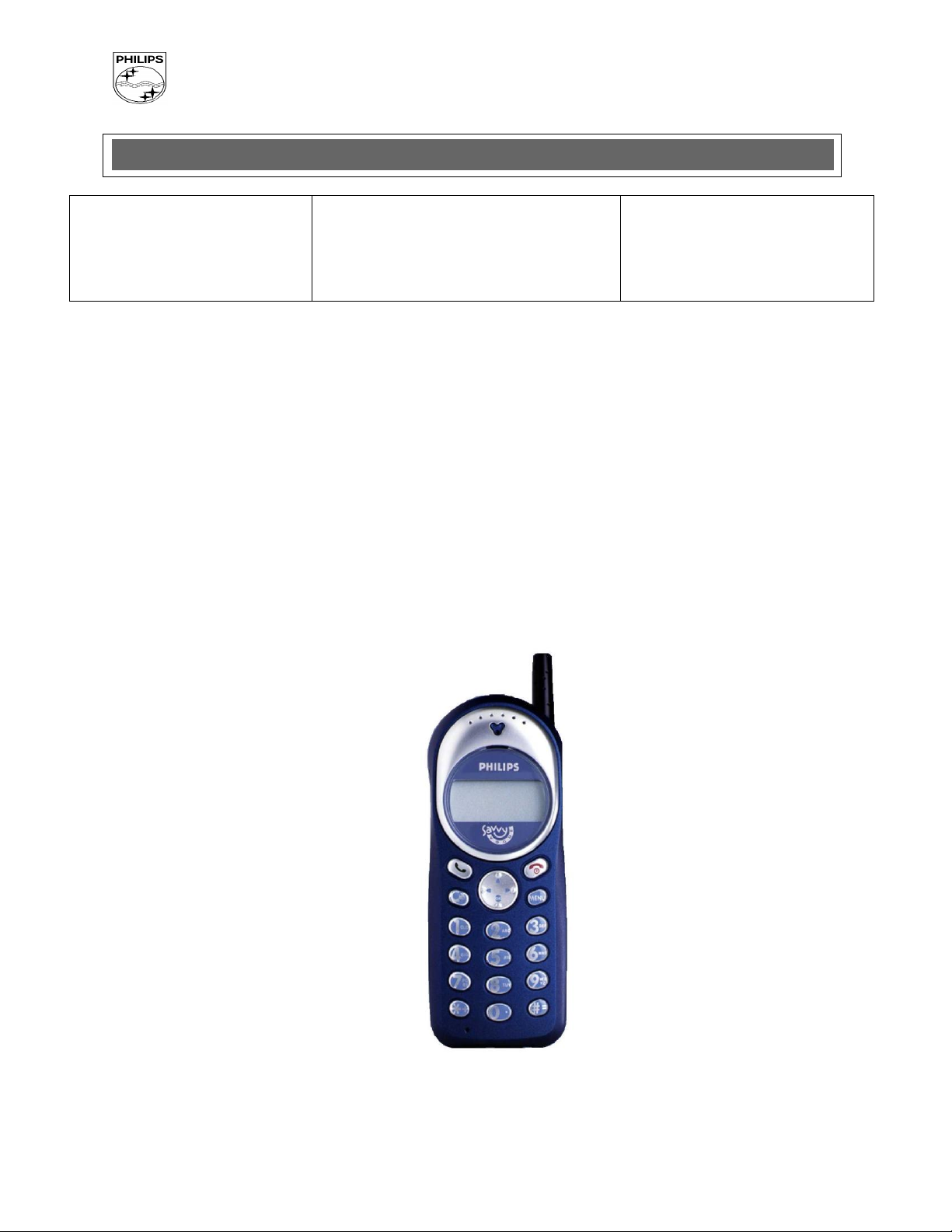
Service Manual
Repair for Cellular Telephone
SAVVY VOGUE DUAL BAND
Level 1 & Level 2
- 1 - PCC/VY/691/E/TCD188LVL2/0026/TF/MLD
Philips Consumer Communications
PHILIPS
CUSTOMER SERVICES
Author : Fabrice Tant
Approval : Jean Pierre Hollande
Operational Manager
SERVICE REPAIR SUPPORT
PROCEDURE
PCC/VY/691/E/TCD188LVL2/0026/TF/MLD
Creation
Date : 26/06/2000
Page : 2 of 30
DATE
MODIFICATION
PAGE
27/06/2000
CREATION
Service Manual
Updated dates:
- 2 - PCC/VY/691/E/TCD188LVL2/0026/TF/MLD

Philips Consumer Communications
PHILIPS
CUSTOMER SERVICES
Author : Fabrice Tant
Approval : Jean Pierre Hollande
Operational Manager
SERVICE REPAIR SUPPORT
PROCEDURE
PCC/VY/691/E/TCD188LVL2/0026/TF/MLD
Creation
Date : 26/06/2000
Page : 3 of 30
CONTENTS
1.0 PURPOSE ................................................................................................................................................................... 4
2.0 SCOPE ........................................................................................................................................................................ 4
3.0 REFERENCE ............................................................................................................................................................. 4
4.0 GLOSSARY / ACRONYM LIST ............................................................................................................................. 4
5.0 TEST EQUIPMENT AND TOOLS .......................................................................................................................... 4
6.0 TEST & INSPECTION PLAN .................................................................................................................................. 5
6.1 USER INTERFACE TEST ............................................................................................................................................. 5
6.2 RF TEST .................................................................................................................................................................... 5
7.0 BEFORE YOU START ............................................................................................................................................. 6
7.1 DESCRIPTION OF THE TRANSCEIVER .................................................................................................................... 6
7.2 THE DISPLAY ....................................................................................................................................................... 7
7.3 INSERTING THE SIM CARD (MICRO). ................................................................................................................... 8
7.4 INSERTING THE BATTERY AND BATTERY COVER. ............................................................................................... 8
7.5 REMOVING THE BATTERY COVER AND BATTERY................................................................................................ 9
7.6 CHARGING THE BATTERY .................................................................................................................................... 9
8.0 TEST PROCEDURES ............................................................................................................................................. 10
8.1 INITIAL FUNCTIONAL CHECK FOR TCD168 SAVVY DUAL BAND....................................................................... 10
8.2 RF TEST ............................................................................................................................................................ 13
8.3 CHARGING IGN (IGNITION) - BATTERY ............................................................................................................ 16
9.0 ASSEMBLY / DISMANTLEMENT PROCEDURES .................................................................................... 17
9.1 DISMANTLEMENT .............................................................................................................................................. 17
9.2 ASSEMBLY ........................................................................................................................................................ 18
9.3 OVERVIEW ........................................................................................................................................................ 23
10.0 SOLUTIONS IN CASE OF PROBLEM DURING TESTS ............................................................................ 25
10.1 THE MOBILE DOES NOT SWITCH ON ................................................................................................................... 25
10.2 CHARGE DOES NOT START OR NO CHARGER DETECTION .................................................................................... 25
10.3 THE DISPLAY SHOW “NO SIM CARD. PLEASE INSERT YOUR SIM CARD.” OR “SIM FAILURE” ....................... 25
10.4 DISPLAY PROBLEMS .......................................................................................................................................... 25
10.5 BUZZER PROBLEMS ........................................................................................................................................... 26
10.6 NO SOUND IN LOUDSPEAKER ............................................................................................................................ 26
10.7 COMMUNICATIONS PROBLEMS .......................................................................................................................... 26
10.8 DEFECTIVE ANTENNA ........................................................................................................................................ 26
10.9 KEYBOARD PROBLEMS ...................................................................................................................................... 26
10.10 CAN’T SEND SMS MESSAGES ............................................................................................................................ 26
- 3 - PCC/VY/691/E/TCD188LVL2/0026/TF/MLD
Philips Consumer Communications
PHILIPS
CUSTOMER SERVICES
Author : Fabrice Tant
Approval : Jean Pierre Hollande
Operational Manager
SERVICE REPAIR SUPPORT
PROCEDURE
PCC/VY/691/E/TCD188LVL2/0026/TF/MLD
Creation
Date : 26/06/2000
Page : 4 of 30
Window or Bezzel
Protective plastic over the LCD display
SW
Software
PN
Hardware configuration of the Mobile
CN
Matrix for types of SW used on the different Hardware
HW
Hardware
ASC
Authorized Service Center
NSC
National Service Center
Test SIM card
Use for functionality of Philips Mobiles
Test SIM card “SP”
SIM card used to simulate user interface and allows radio tests
1.0 PURPOSE
This document establishes the functional test procedures for service repair of SAVVY VOGUE transceiver.
2.0 SCOPE
The test plan is applicable to all level of service repair of SAVVY VOGUE transceiver.
3.0 REFERENCE
4.0 GLOSSARY / ACRONYM LIST
5.0 TEST EQUIPMENT AND TOOLS
Equipment / Tools
Production Test SIM Card - Part No. : 4311 255 00781
Test SIM Card “SP” - Part No. : 4311 255 00782
RF Cable - Part No. : 941-555-1 (AMP)
Digital Multimeter - Recommended Model : Fluke
Specification with current reading in mA
- 4 - PCC/VY/691/E/TCD188LVL2/0026/TF/MLD
Philips Consumer Communications
PHILIPS
CUSTOMER SERVICES
Author : Fabrice Tant
Approval : Jean Pierre Hollande
Operational Manager
SERVICE REPAIR SUPPORT
PROCEDURE
PCC/VY/691/E/TCD188LVL2/0026/TF/MLD
Creation
Date : 26/06/2000
Page : 5 of 30
6.0 TEST & INSPECTION PLAN
The following test & inspection plan is derived from the Product Test Reference for SAVVY VOGUE.
6.1 User Interface Test
Using of TEST SIM Card “SP” / Production to test DUT as follow:
On/Off Button
LCD Back-light
Keyboard Test
Buzzer Test
Audio Test
Antenna Test
LCD
IMEI
E-prom Status
Production Number
Transceiver 12NCs & Software Version
With a fast charger connected to the PRODUCT car-kit, perform check on charging IGN (Ignition) – Battery.
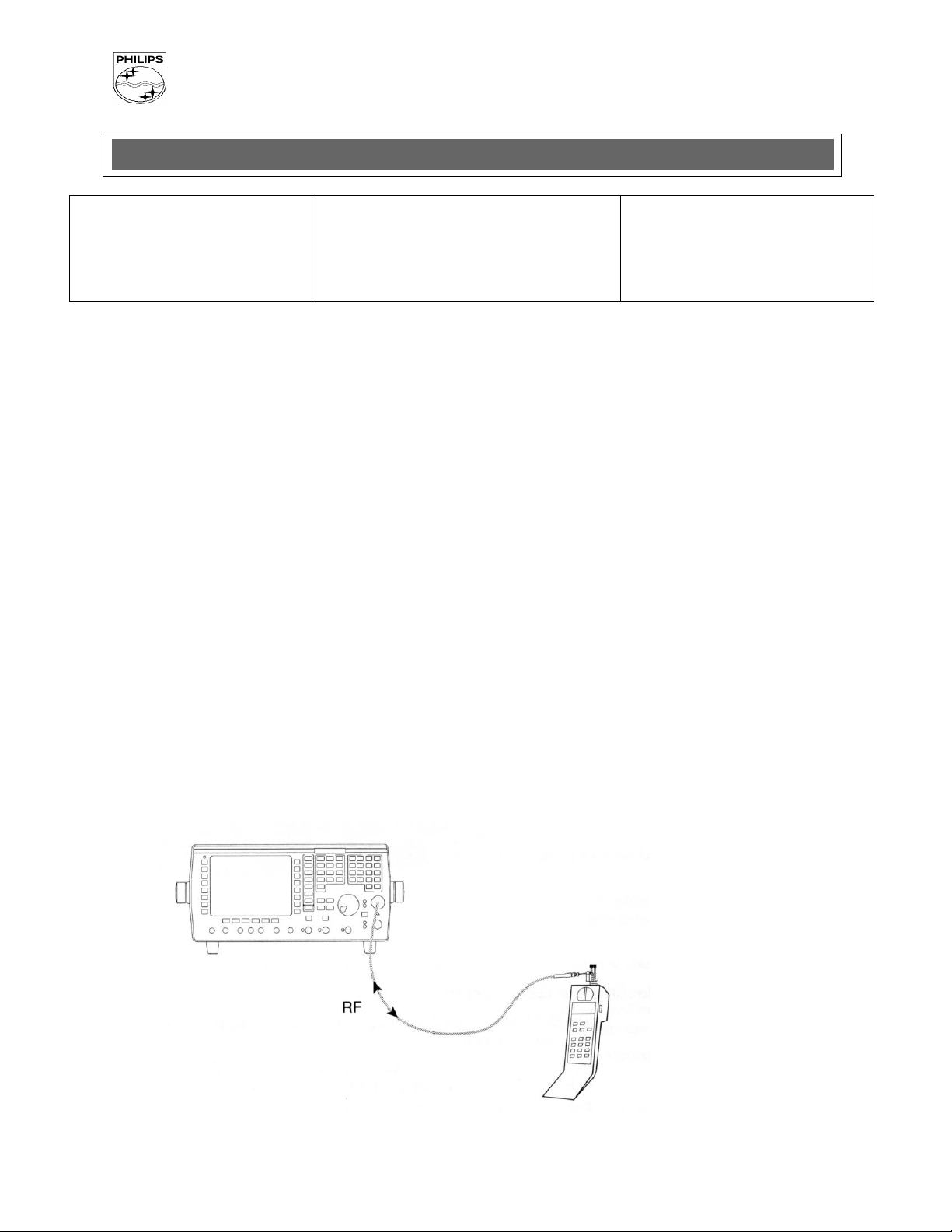
6.2 RF Test
The radio test must be performed with a Digital Radio Test Set connected with the specific RF
cable to the mobile RF connector.
- 5 - PCC/VY/691/E/TCD188LVL2/0026/TF/MLD
Philips Consumer Communications
PHILIPS
CUSTOMER SERVICES
Author : Fabrice Tant
Approval : Jean Pierre Hollande
Operational Manager
SERVICE REPAIR SUPPORT
PROCEDURE
PCC/VY/691/E/TCD188LVL2/0026/TF/MLD
Creation
Date : 26/06/2000
Page : 6 of 30
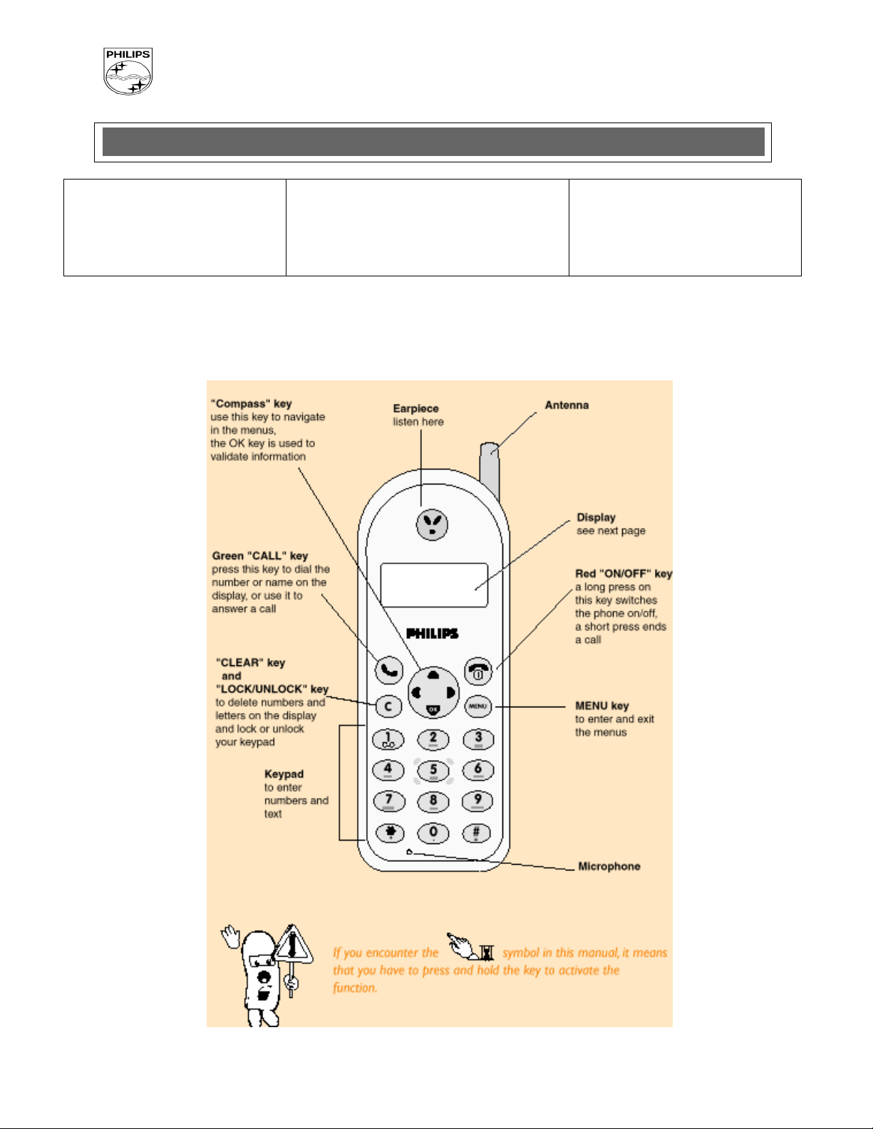
7.0 Before You Start
7.1 Description of the transceiver
- 6 - PCC/VY/691/E/TCD188LVL2/0026/TF/MLD
Philips Consumer Communications
PHILIPS
CUSTOMER SERVICES
Author : Fabrice Tant
Approval : Jean Pierre Hollande
Operational Manager
SERVICE REPAIR SUPPORT
PROCEDURE
PCC/VY/691/E/TCD188LVL2/0026/TF/MLD
Creation
Date : 26/06/2000
Page : 7 of 30
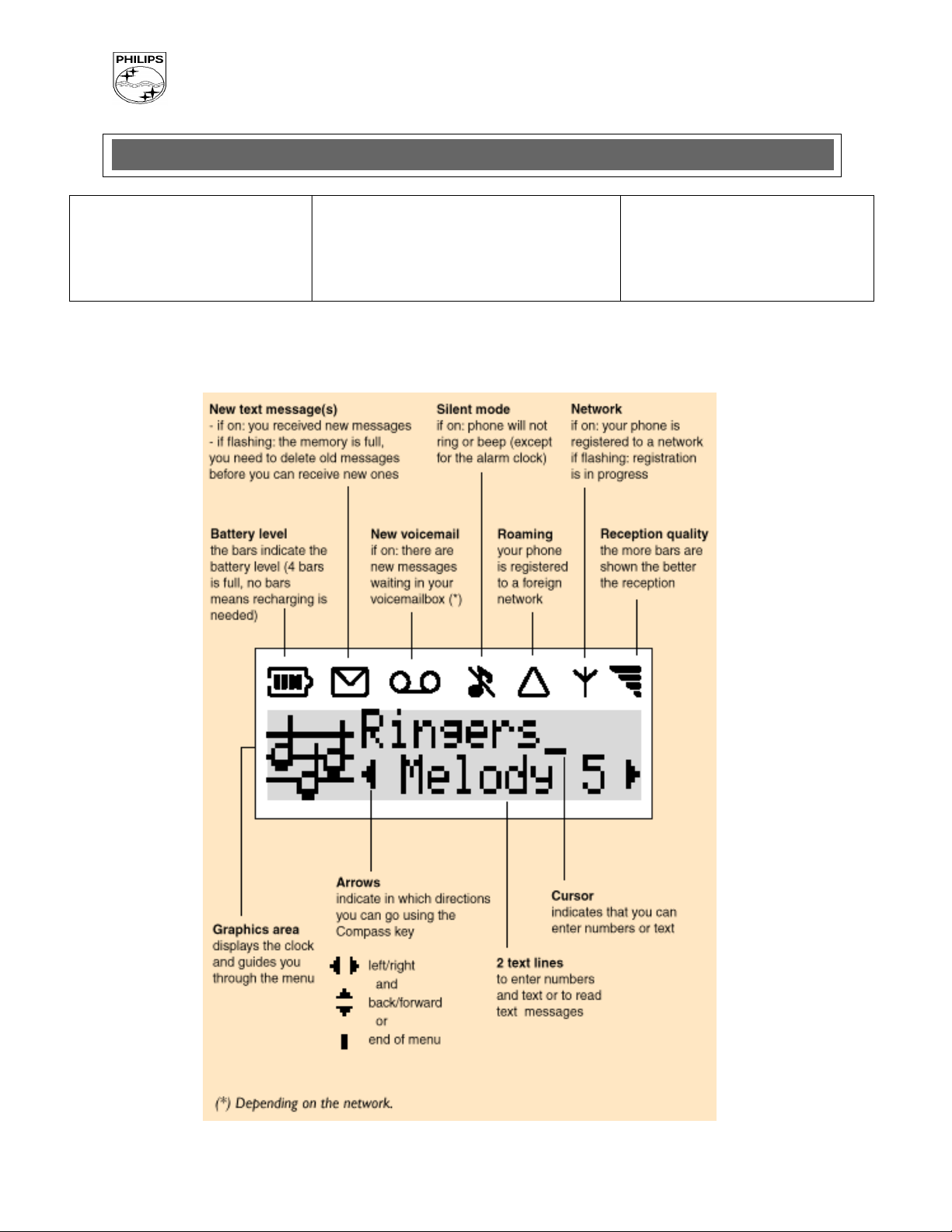
7.2 The display
- 7 - PCC/VY/691/E/TCD188LVL2/0026/TF/MLD
Philips Consumer Communications
PHILIPS
CUSTOMER SERVICES
Author : Fabrice Tant
Approval : Jean Pierre Hollande
Operational Manager
SERVICE REPAIR SUPPORT
PROCEDURE
PCC/VY/691/E/TCD188LVL2/0026/TF/MLD
Creation
Date : 26/06/2000
Page : 8 of 30
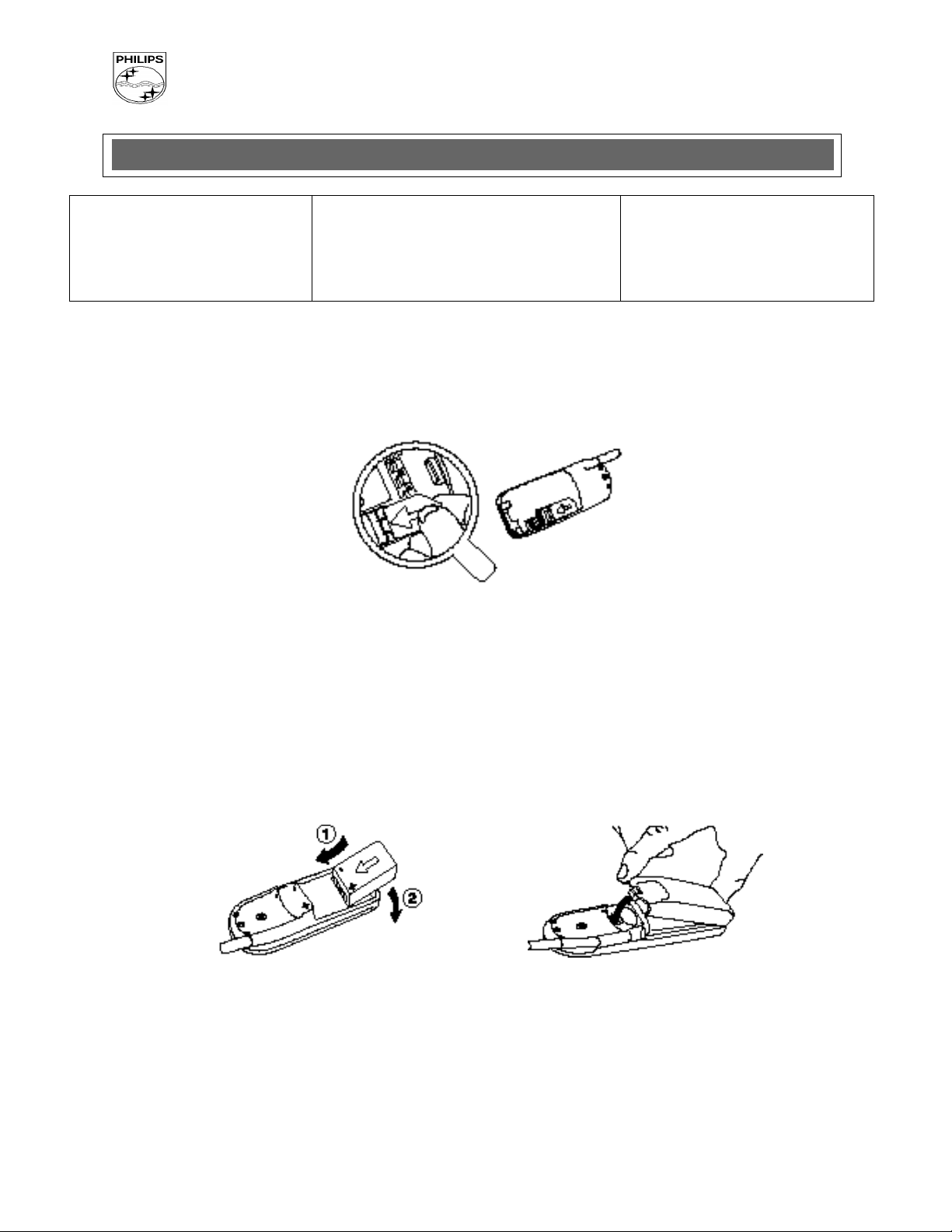
7.3 Inserting the SIM card (Micro).
7.3.1 Remove the SIM card from its support and slide the card into the appropriate slot in the battery compartment (the chip must be facing inwards and towards the bottom of the transceiver).
7.4 Inserting the Battery and Battery Cover.
7.4.1 Slide the battery onto the contact near the middle of the transceiver, and press the battery in place.
7.4.2 Hook the battery cover onto the hinges on bottom of transceiver and press forward until the latch catches.
- 8 - PCC/VY/691/E/TCD188LVL2/0026/TF/MLD
Philips Consumer Communications
PHILIPS
CUSTOMER SERVICES
Author : Fabrice Tant
Approval : Jean Pierre Hollande
Operational Manager
SERVICE REPAIR SUPPORT
PROCEDURE
PCC/VY/691/E/TCD188LVL2/0026/TF/MLD
Creation
Date : 26/06/2000
Page : 9 of 30
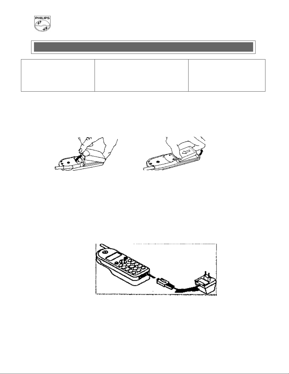
7.5 Removing the Battery Cover and Battery.
7.5.1 Press on the latch on the back of the transceiver and lift off the battery cover. Lift up on the bottom of the battery and remove from the transceiver.
7.6 Charging the battery
7.6.1 With the battery attached to the phone, plug the connector into the right socket at the base of
the phone.
7.6.2 Plug the transformer unit into an AC power socket.
7.6.3 The battery icon on the transceiver’s display indicates the state of the charge process:
Bars moving - means the battery is charging.
Steady - means the battery is fully charged.
If the battery is completely discharged, the battery icon will only appear 2 to 3 minutes after
you connect the charger.
- 9 - PCC/VY/691/E/TCD188LVL2/0026/TF/MLD
 Loading...