

Philips SAA7811HL Datasheet
DATA SH EET
Preliminary specification
File under Integrated Circuits, IC22
1999 Oct 05
INTEGRATED CIRCUITS
SAA7811HL
Single-chip DVD-ROM

1999 Oct 05 2
Philips Semiconductors Preliminary specification
Single-chip DVD-ROM SAA7811HL
FEATURES
Host interface
• Enhanced Integrated DriveElectronics (IDE) Advanced
TechnologyAttachmentProgramInterface(ATAPI)host
interface
• Built-in 12-byte ATAPI Packet command First-In,
First-Out (FIFO)
• Supports Advanced Technology Attachment (ATA) and
ATA-2 PIO and multi-word Direct Memory Access
(DMA) data transfer modes
• Supports ATA/ATAPI-4 Ultra DMA transfer modes with
data rate up to 33 MBytes/s
• Configurable as generic DMA interface, for use with
external host interface devices
• Automatic sequencing of ATAPI packet command
protocol; including command termination
• Automatic determination of block length for mode2,
form 1 and form 2 sectors (block length transferred is
programmable).
Block decoder
• Supports CD-ROM, CD-R and CD-R/W; CD-DA and
DVD-ROM formats
• Supports real time error detection and correction in
hardware for CD-ROM mode
• CD-ROM error corrector switchable between single or
dual pass (both with Error Detection/Correction [EDC])
• Internal registers are memory-mapped
• Embedded DVD-video authentication module.
Buffer memory controller
• Supports up to 2 MBytes of DRAM buffer
• Block based sector addressing.
Channel decoder
• Selectable differential and single-ended HF inputs;
compatible with TZA1033 (DVDalas2plus) and
TZA1020A (Aeger2); single-ended input has
bypassable AGC
• Internal 6-bit ADC
• Digital PLL and slicer for HF clock regeneration
• Supports Eight-to-Fourteen Modulation
(EFM) and EFM+ demodulation
• Full CD error correction strategy; t = 2 ande=4
• On-chip CD error corrector memory with ±8 frame jitter
margin
• Built-in hardware for double pass DVD error corrector;
(can correct 5 errors in C1 frame and 16 errors in
C2 frame)
• Error corrector monitor signal available
• I2C-bus output available via programmable vampire
pins.
Spindle motor control
• Advanced motor control loop allows Constant Angular
Velocity (CAV), Constant Linear Velocity (CLV) and
pseudo-CLV playback
• Support for 3-pin and 1-pin tacho control
• Motor control via incoming bit stream or tacho.
Speed operation
• Supports up to 56 × CD-ROM playback
• Supports up to 10 × DVD-ROM playback.
Multimedia functions and built-in DAC
• Supports audio playback via DRAM buffer; allows audio
discs to be played at higher speeds
• IEC958 (SPDIF, AES/EBU and DOBM) output with
Q to W subcode bits and programmable category code,
output at n = 1 rate
• Built-in digital audio DAC including: −4 × oversampling
filter
• Built-in digital volume control, attenuator and
single-sample interpolator
• Separate left and right channel routing and mute control.
Microcontroller interface
• Embedded microcontroller can operate as 33 MHz or
67 MHz equivalent 80C51
• Embedded co-processor for fast multiply, divide, shift,
and normalize instructions; supported by C-compilers
• Co-processor for MSF calculations
• Memory mapped interfaces to sub functions
• External microcontroller support

1999 Oct 05 3
Philips Semiconductors Preliminary specification
Single-chip DVD-ROM SAA7811HL
• Embedded SRAM (1.5 kbytes Xdata, 512 bytes Idata,
224 bytes data and registers)
• 4 banks: on Idata and registers; for better multi-tasking
support
• External flash EPROM programming support
– Serial boot possible with empty flash EPROM
– Internal program upload support.
• Code space support up to 1 Mbyte through built-in bank
switching
• Debug interface for embedded microcontroller.
Servo processor
• Switched current analog-to-digital converters for diode
and error signal inputs
• Selectable servo error or servo diode inputs
• Focus and radial servo loops
• Automatic closed loop gain control available for focus
and radial loops
• Built-in access procedure with fast track count input
• High-speed track crossing velocity measurement
(>350 kHz) for CD and DVD
• Special DVD track crossing support
• Fast radial brake circuitry
• EFM actuator damping circuitry
• SledgemotorservoloopwithenhancedPositionControl
Sledge (PCS) support
• Sledge stepper motor support
• Adaptive Repetitive Control (ARC)
• Debug interface for servo.
Clock multiplier
• On-chip clock multipliers allows the use of 8.4672 MHz
crystal.
Disclaimer
SupplyofthisCompactDiscICdoesnotconveyanimplied
license under any patent right to use this IC in any
Compact Disc application.
GENERAL DESCRIPTION
The SAA7811 is a single-chip device for high speed
DVD-ROM applications. The device contains the following
blocks previously contained in separate ICs:
• channel decoder
• block decoder
• servo processor
• microcontroller.
QUICK REFERENCE DATA
Note
1. The analog and digital core supply pins (V
DDA
and V
DDD(CO)
) must be connected to the same external supply.
ORDERING INFORMATION
SYMBOL PARAMETER MIN. TYP. MAX. UNIT
V
DDD(CO)
supply voltage digital part core; note 1 3.0 3.3 3.6 V
V
DDD1(3P)
supply voltage digital part pad cells 3 V 3.0 3.3 3.6 V
V
DDD2(5P)
supply voltage digital part pad cells 5 V 4.5 5.0 5.5 V
V
DDA
supply voltage analog part; note 1 3.0 3.3 3.6 V
I
DD
supply current − tbf − mA
f
XTAL
crystal frequency 8 8.4672 35 MHz
T
amb
operating ambient temperature 0 − 60 °C
T
stg
storage temperature −55 − +125 °C
TYPE NUMBER
PACKAGE
NAME DESCRIPTION VERSION
SAA7811HL LQFP208 plastic low profile quad flat package; 208 leads; body 28 × 28 × 1.4 mm SOT459-1
1999 Oct 05 4
Philips Semiconductors Preliminary specification
Single-chip DVD-ROM SAA7811HL
This text is here in white to force landscape pages to be rotated correctly when browsing through the pdf in the Acrobat reader.This text is here in
_white to force landscape pages to be rotated correctly when browsing through the pdf in the Acrobat reader.This text is here inThis text is here in
white to forcelandscapepagesto be rotated correctly when browsing through the pdf in the Acrobat reader. white to force landscape pages to be ...
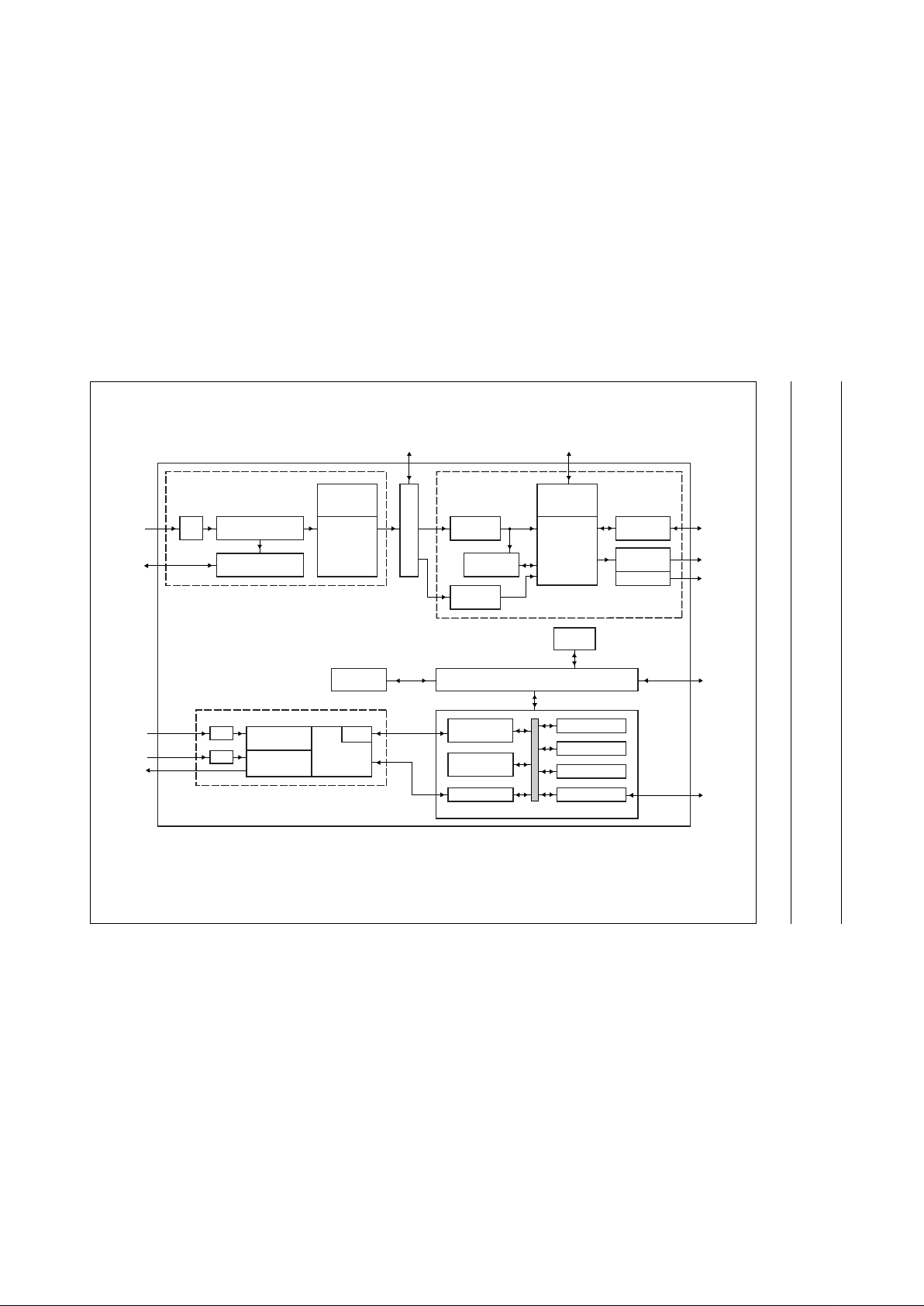
BLOCK DIAGRAM
handbook, full pagewidth
CHANNEL DECODER
BIT DETECTOR
AND DEMODULATOR
MEMORY
PROCESSOR
CD/DVD
ERROR
CORRECTOR
BLOCK DECODER
INTERFACE
DRIVE
INTERFACE
HOST
INTERFACE
SUBCODE
INTERFACE
ERROR
CORRECTOR
MEMORY
PROCESSOR
DRAM
INTERFACE
CSS
MODULE
CPU INTERFACE
CONTROL
REGISTERS
MOTOR/
TACHO INTERFACE
ADC
MULTIMEDIA
INTERFACE
DAC
SERVO
PCS
ACCELERATOR
SERVO
ACCELERATOR
SERVO
PROCESSOR
RAM
MICROCONTROLLER
SAA7811
ADDRESS
DECODER
1.5 KBYTES
AUXILIARY RAM
SFRs PORT REGS
736-BYTE RAM
1.5 KBYTES ROM
CPU
FCE404
ADC
ADC
Fig.1 Block diagram.

1999 Oct 05 5
Philips Semiconductors Preliminary specification
Single-chip DVD-ROM SAA7811HL
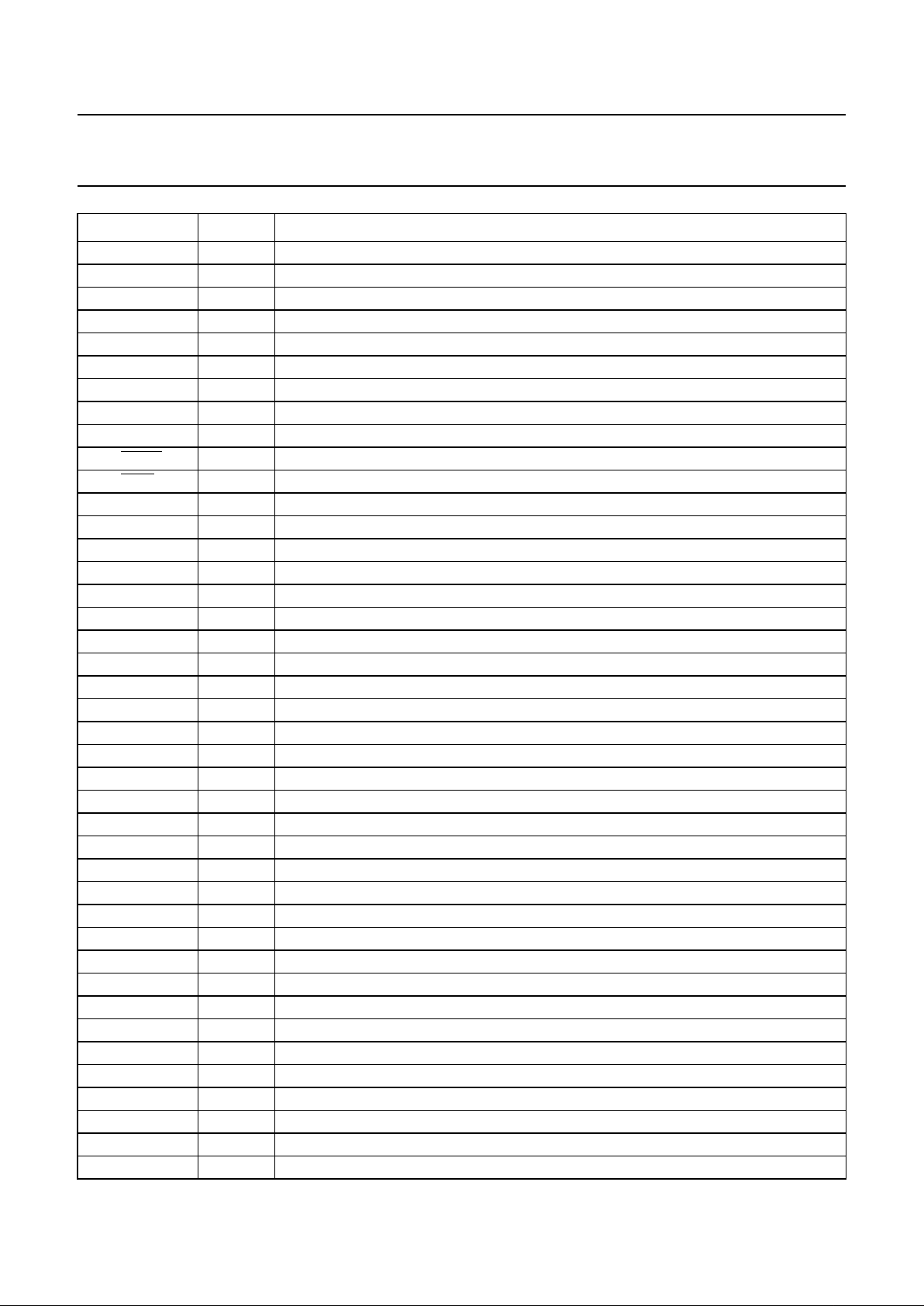
PINNING
See note 1
SYMBOL PIN DESCRIPTION
V
DDD1(3P)
1 pad digital supply (3.3 V)
V
SSD1(3P)
2 pad digital ground (3.3 V)
T1 3 tacho 1 input, tcb_tck_pregate
T2 4 tacho 2 input
T3 5 tacho 3 input
DAC/RP 6 DAC differential outputright (positive)/debug signal from MACE (opc_int)
DAC/RN 7 DAC differential output right (negative)/debug signal from MACE (servo_int)
DAC_VPOS 8 DAC V
ref
(positive)
DAC_VNEG 9 DAC V
ref
(negative)
DAC_LP 10 DAC differential output left (positive)/debug signal from MACE (dakota_int0)
DAC_LN 11 DAC differential output left (negative)/debug signal from MACE (dakota_int1)
TEST1 12 test input, tcb_tms and tcb_tdi connected to an internal pull-down resistor
TEST2 13 test input, tcb_trstn connected to an internal pull-down resistor
CRIN 14 clock input
CROUT 15 clock output
V
DDA
16 analog supply (3.3 V)
V
SSA
17 analog supply ground
HFIN_DN 18 differential HF in (negative)
HFIN_DP 19 differential HF in (positive)
HFIN_SE 20 single-ended HF in (AGC)
VCOM 21 common mode reference signal (DVDalas2plus)
I
ref
22 analog current reference
WREFLO 23 V
ref
low; connect to V
SSA
via capacitor
TEST3 24 test input; connect to V
SSA
V
SSA
25 analog supply ground
V
DDA
26 analog supply (3.3 V)
SIN_PHI 27 sine input from hall detectors
COS_PHI 28 cosine input from hall detectors
TEST4 29 test input; connect to V
SSA
XDET 30 auxiliary ADC input
ACT_EMFP 31 EMF of the actuator; positive input
ACT_EMFN 32 EMF of the actuator; negative input
TEST5 33 test input; connect to V
SSA
TEST6 34 test input; connect to V
SSA
TEST7 35 test input; connect to V
SSA
UOPB 36 decoupling point for ADC ladder
UOPT 37 upper reference voltage for ADC ladder
ALPHA0 38 gain control for TZA1030 (DROPPI)
V
SSA
39 analog supply ground
1999 Oct 05 6
Philips Semiconductors Preliminary specification
Single-chip DVD-ROM SAA7811HL
V
DDA
40 analog supply (3.3 V)
D1 41 diode input
D2/TLN 42 diode input (normalized); track-loss signal
D3/REN 43 diode input (normalized); radial error signal
D4/FEN 44 diode input (normalized); focus error signal
S1/MIRN 45 satellite diode (normalized); mirror signal
S2 46 satellite diode
VRIN 47 I/O voltage reference; for servo ADC
FTCH 48 track count input
P5_7/
DEFO 49 defect output (active LOW)/general purpose I/O
P5_6/
DEFI 50 defect input (active LOW)/general purpose I/O
P5_5/TL 51 track-loss means output/general purpose I/O
P5_4/RP/FOK 52 radial polarity/focus OK/general purpose I/O
P5_3/CE1 53 CS external SRAM/programmable I/O
P5_2/CLO 54 servo clock output/alpha0 step pulse for LADIC
P5/SDA 55 I
2
C-bus data/general purpose I/O
P5_0/SCL 56 I
2
C-bus clock/general purpose I/O
RA 57 radial output (3-state during reset)
SL 58 sledge output (3-state during reset)
FO 59 focus output (3-state during reset)
RAC_SW 60 disconnects radial actuator (active HIGH)
REF_SIN 61 pulse density modulated reference signal; removes DC offset from sin_phi
REF_COS 62 pulse density modulated reference signal; removes DC offset from cos_phi
V
DDD1(3P)
63 pad digital supply (3.3 V)
V
SSD1(3P)
64 pad digital ground (3.3 V)
P4_7/PXT2EN 65 timer 2 input enable/SIDA for DVDalas2plus
P4_6/PXT2 66 timer 2 clock input/SICL for DVDalas2plus
P4_5/PXT0 67 timer 1 clock input/SILD for DVDalas2plus
P4_4/PXT 68 timer0 clock input/CS2 for external device
V
DDD(3CO)
69 core digital supply (3.3 V)
V
SSD(3CO)
70 core digital ground
P4_3/A19 71 A19 to EPROM
P4_2/A18 72 A18 to EPROM
P4_1/A17 73 A17 to EPROM
P4_0/A16 74 A16 to EPROM
UA15 75 port 2; upper microcontroller address lines
UA14 76 port 2; upper microcontroller address lines
UA13 77 port 2; upper microcontroller address lines
UA12 78 port 2; upper microcontroller address lines
UA11 79 port 2; upper microcontroller address lines
UA10 80 port 2; upper microcontroller address lines
SYMBOL PIN DESCRIPTION
 Loading...