

Philips SAA7780 Datasheet

INTEGRATED CIRCUITS
SAA7780
ThunderBird Q3D PCI Audio Accelerator
Product specification 1999 Sep 30

ThunderBird Q3D PCI Audio SAA7780
Philips Semiconductors
Product Specification
Accelerator
• Add's reverb as an additional positional que
• Reverb preset's can be applied to any
DirectSound3D application
• EAXTM Compatible
• QXpanderTM and Stereo to 3D remapping
• Second Generation ActiMediaTM ProgrammableDSP architecture
• Comprehensive Real Mode DOS and DOS window
support
FEATURES
• Full H/W acceleration of 64 audio sources
• 64 H/W sample fetch channels
• 64 H/W sample rate convertors
• H/W mixing of 64 streams
• H/W DSP filter/effects/music synthesis applied
to 64 streams
• Concurrent processing of up to 384 audio sources
• Up to 64 DirectSound/wavetable sources processed in H/W
• 64 plus DirectSound sources processed on host
• Up to 128 total DirectSound sources
• Up to 64 3D sources
• Up to 64 H/W wavetable voices
• Up to 256 host wavetable voices
• QSound3DInteractiveTM interactive positional 3D
• H/W DSP processing for maximum performance
• Stereo speaker, headphone and quad speaker
algorithms
• Proprietary technology eliminates crosstalk cancellation and broadens "sweet spot"
• A3DTM compatible
• QSound Multi-Speaker SystemTM stereo-to-quad processing
• Transforms ordinary stereo applications to quadraphonic
• Non-3D games become immersive quad 3D
games
• Enhanced DVD movie playback
• True quadraphonic music playback from CD's,
music DVD's and MP3 players
• Effective with both stereo and Dolby Pro-LogicTM
encoded material
• QSound Environmental ModelingTM
• SoundBlaster ProTM Compatibility
• PC/PCI, DDMA and LAMTM PCI DMA support
• FM, MIDI stereo and MIDI quad music in Real
Mode DOS
• Supports low cost AC97 1.0 and serial stereo DAC
output
• Dual gameport accelerator with legacy and digital
joystick modes
• Integrated 16650 UART for Modem or other serial
port applications
• Windows
NT 5.0 (WDM) Drivers
• 0.35u TLM manufacturing technology
• 3.3v operation with 5v tolerant I/O
(R)
95, Windows
(R)
98, and Windows
GENERAL DESCRIPTION
The SAA7780 ThunderBird Q3DTM is a high-performance PCI audio accelerator targeting PC gaming
and music applications. Developed by QSound Labs
and Philips Semiconductors, it combines the most
compelling 3D, quadraphonic and music synthesis
technologies available with the powerful yet cost
effective ActiMediaTM DSP architecture. Full H/W
acceleration of DirectSoundTM, 3D audio, music synthesis, and gameport functions guarantees exceptional system performance. QSound's new Q3DTM
algorithms not only render exceptional 3D soundscapes for 3D applications but add a new dimension
to stereo applications using their unique stereo-to-3D
and stereo-to-quad remapping capabilities. Three
available PCI DMA modes assure full SoundBlaster
ProTM compatibility on most platforms without additional hardware. The Intel AC97 architecture provides high audio quality using a low cost AC97
codec.
(R)
1999 Sep 30 2 853-2174 22449

ThunderBird Q3D PCI Audio SAA7780
Philips Semiconductors
Product Specification
Accelerator
ORDERING INFORMATION
TYPE
NUMBER
NAME DESCRIPTION VERSION
PACKAGE
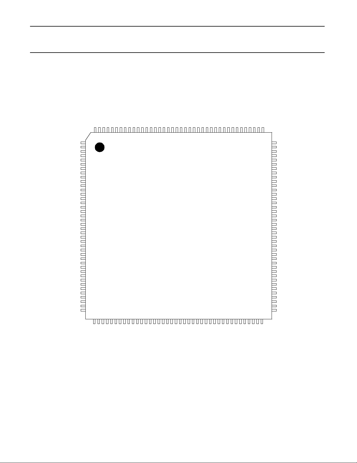
SAA7780 QFP160 plastic quad flat pack; 160 leads (lead length 1.60 mm); body
28 x 28 x 3.42 mm
QUICK REFERENCE DATA
Condition Symbol Maximum Ratings
Ambient Operating Temperature T
Ambient Storage Temperature T
A
S
Non-Operating Core and Ring Supply Voltage VDD, VDDIC -0.5V to 4.6V *
Operating Core Supply Voltage VDDIC -0.5V to 3.63V *
Operating Ring Supply Voltage VDD 3.0V to 3.63V *
5V Tolerant Supply (5.0V nominal supply) NWELL -0.5V to 5.5V *
NWELL to VDD Differential NWELL-VDD 0 ≤ (NWELL-VDD) < 4.0V
0°C to +70°C
-65°C to +150°C
25-90019
3V Tolerant I/O DC Input Voltage V
3V Tolerant I/O DC Output Voltage V
5V Tolerant I/O DC Input Voltage V
5V Tolerant I/O DC Output Voltage V
DC Input Current (at VI < 0V or VI > VDD) I
DC Output Current (at VO < 0V or VO > VDD) I
Power Dissipation P
I3
O3
I5
O5
I
O
D
-0.5V to VDD+0.5V (≤ 4.6V max)+
-0.5V to VDD+0.5V (≤ 4.6V max)+
-0.5V to 5.5V (≤ 6.0V max)+
-0.5V to VDD+0.5V (≤ 4.6V max)+
± 20mA
± 20mA
500mW
*Refer to Section 3.1 to ensure proper power supply sequencing as well as voltage ranges.
+Items in parenthesis are non-operating conditions.
1999 Sep 30 3
ThunderBird Q3D PCI Audio SAA7780
Philips Semiconductors
Product Specification
Accelerator
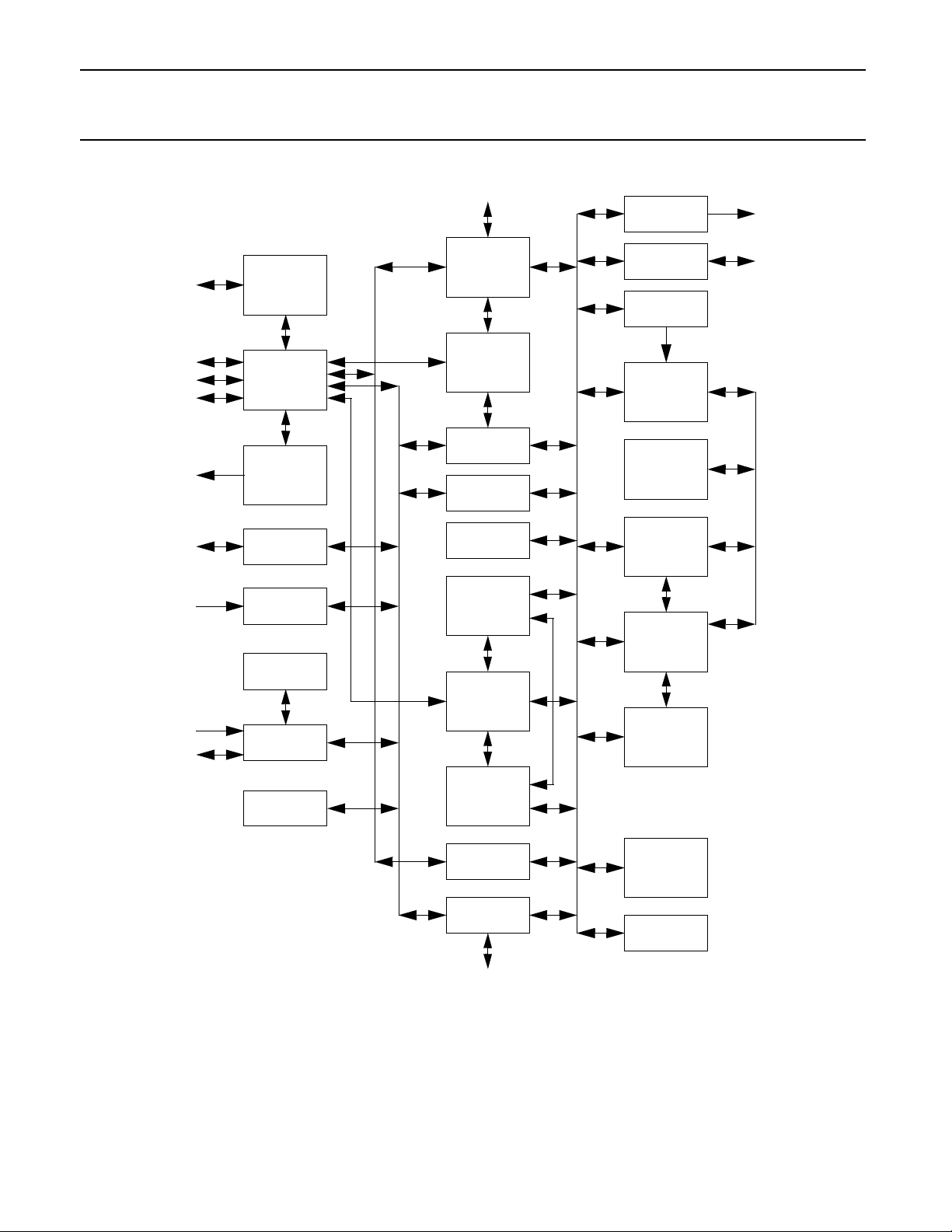
FIGURE 1 BLOCK DIAGRAM
Serial
CFG
Port
PCI
Bus
Test
Port
INTA#
Port
Port
Xtal
PCI
Configuration
Headers
PCI
Master/Slave
Interface
Serial
Interrupt
Controller
16650
UART
Game Port
Interface
PLL
Test Logic
PLL Cell
Multimedia
Timer
32 BIT DMA BUS
16 BIT PS BUS
32 BIT VREG BUS
8 BIT PS/VPB BUS
AC Link Interface
AC Link
& the DMD
Interface
Legacy
DMA
Interface
SoundBlaster
Registers
OPL3
Registers
FM
Accelerator
Sample Fetch
Accelerator
Virtual
Registers
Address
Generation
(2/64x24,
2/64x36)
DAC
Interface
General
Purpose I/O
DSP Interrupt
Controller
INTRs
Pine
DSP DATA BUS
DSP Core
DSP Code
ROM
DSP Code
Patch RAM
DSP
Memory
Controller
DSP Data
RAM
Serial
DAC
Port
GPIO
DSP CODE BUS
1999 Sep 30 4
Host/DSP
Interface
MIDI Regs
and UART
MIDI Interface
Prog
IIR Filter
Phase/Env
Accelerator

ThunderBird Q3D PCI Audio SAA7780
Philips Semiconductors
Product Specification
Accelerator
PINNING
PIN # PIN NAME PIN # PIN NAME PIN # PIN NAME PIN # PIN NAME PIN # PIN NAME
1 VDD 35 PCGNT# 69 TRDY# 103 MD15 137 MA10
2 SYNC 36 PCREQ# 70 DEVSEL# 104 VSS 138 VDDIC
3 BIT_CLK 37 GNT# 71 STOP# 105 MD14 139 MA11
4 SDATA_OUT 38 REQ# 72 PERR# 106 MD13 140 MA12
5 SDATA_IN 39 AD31 73 SERR# 107 MD12 141 MA13
6 AC_RST# 40 VSS 74 VSS 108 MD11 142 VDD
7 JAB1 41 VDD 75 PAR 109 MD10 143 MA14
8 JBB1 42 AD30 76 C/BE1# 110 MD9 144 MCS#
9 JACX 43 AD29 77 AD15 111 MD8 145 TXD
10 JBCX 44 AD28 78 AD14 112 VDD 146 RXD
11 MIDIOUT 45 AD27 79 AD13 113 MD7 147 VSSIC
12 JBCY 46 AD26 80 VDD 114 MD6 148 RTS#
13 JACY 47 VSS 81 VSS 115 MD5 149 DTR#
14 JBB2 48 AD25 82 AD12 116 MD4 150 CTS#
15 VSS 49 AD24 83 AD11 117 NWELL 151 DSR#
16 JAB2 50 C/BE3# 84 VDD 118 MD3 152 DCD#
17 VSSIC 51 IDSEL 85 AD10 119 MD2 153 RI#
18 MIDIIN 52 AD23 96 AD9 120 VSS 154 GPIO0
19 PLLAGND 53 AD22 87 AD8 121 VDD 155 GPIO1
20 PSUB 54 VDD 88 C/BE0# 122 MD1 156 GPIO2
21 PLLAPWR 55 AD21 89 AD7 123 MD0 157 MSI
22 PLLDPWR 56 VDDIC 90 VSS 124 MA0 158 MCLK
23 XTALIN 57 AD20 91 AD6 125 MA1 159 MLRCK
24 XTALOUT 58 NWELL 92 AD5 126 MA2 160 VSS
25 PLLDGND 59 AD19 93 AD4 127 MA3
26 VSS 60 VSSIC 94 AD3 128 VSS
27 DSPCLK 61 AD18 95 AD2 129 MA4
28 VDD 62 VSS 96 VDD 130 MA5
29 TRI# 63 AD17 97 AD1 131 MA6
30 NAND# 64 AD16 98 AD0 132 MA7
31 INTA# 65 C/BE2# 99 VDDIC 133 MWE#
32 IRQSER 66 FRAME# 100 CLKRUN# 134 MA8
33 RST# 67 IRDY# 101 CFGDAT 135 VDD
34 PCLK 68 VDD 102 CFGCLK 136 MA9
1999 Sep 30 5
ThunderBird Q3D PCI Audio SAA7780
Philips Semiconductors
Product Specification
Accelerator
FIGURE 2 PIN CONFIGURATION
VSS
MLRCK
MCLK
MSI
GPIO2
GPIO1
GPIO0
RI#
DCD#
DSR#
CTS#
DTR#
RTS#
VSSIC
RXD
TXD
MCS#
MA14
VDD
MA13
MA12
MA11
VDDIC
MA10
MA9
VDD
MA8
MWE#
MA7
MA6
MA5
MA4
VSS
MA3
MA2
MA1
MA0
MD0
MD1
VDD
160
159
158
157
156
155
154
153
152
151
150
149
148
147
146
145
144
143
142
141
140
139
138
137
136
135
134
133
132
131
130
129
128
127
126
125
124
123
122
121
VDD
SYNC
BIT_CLK
SDATA_OUT
SDATA_IN
AC_RST#
JAB1
JBB1
JACX
JBCX
MIDIOUT
JBCY
JACY
JBB2
VSS
JAB2
VSSIC
MIDIIN
PLLAGND
PSUB
PLLAPWR
PLLDPWR
XTALIN
XTALOUT
PLLDGND
VSS
DSPCLK
VDD
TRI#
NAND#
INTA#
IRQSER
RST#
PCLK
PCGNT#
PCREQ#
GNT#
REQ#
AD31
VSS
1
2
3
4
5
6
7
8
9
10
11
12
13
14
15
16
17
18
19
20
21
22
23
24
25
26
27
28
29
30
31
32
33
34
35
36
37
38
39
40
414243444546474849505152535455565758596061626364656667686970717273747576777879
TOP VIEW
SAA7780
120
119
118
117
116
115
114
113
112
111
110
109
108
107
106
105
104
103
102
101
100
80
99
98
97
96
95
94
93
92
91
90
89
88
87
86
85
84
83
82
81
VSS
MD2
MD3
NWELL
MD4
MD5
MD6
MD7
VDD
MD8
MD9
MD10
MD11
MD12
MD13
MD14
VSS
MD15
CFGCLK
CFGDAT
CLKRUN#
VDDIC
AD0
AD1
VDD
AD2
AD3
AD4
AD5
AD6
VSS
AD7
C/BE0#
AD8
AD9
AD10
VDD
AD11
AD12
VSS
1999 Sep 30 6
VDD
AD30
VSS
AD29
AD28
AD27
AD26
AD25
AD24
VDD
AD23
AD22
AD21
IDSEL
C/BE3#
AD20
VDDIC
VSS
AD19
AD18
AD17
VSSIC
NWELL
VDD
AD16
IRDY#
TRDY#
C/BE2#
FRAME#
VSS
PAR
STOP#
PERR#
SERR#
DEVSEL#
VDD
AD15
AD14
AD13
C/BE1#

ThunderBird Q3D PCI Audio SAA7780
Philips Semiconductors
Product Specification
Accelerator
FUNCTIONAL OVERVIEW
True Hardware Acceleration
The ThunderBird PCI
functions are performed on the ActiMediaTM DSP which frees the host CPU to perform other tasks, boosting graphic
frame rates and raising system benchmark performance.
TM
products are true hardware accelerators. Positional 3D, music synthesis and SoundBlasterTM
High Concurrency
Today's multimedia applications demand concurrent, independent audio processing of many diverse audio streams.
Mainstream applications may require 32 or more wavetable synthesis voices and 24 or more sound effects positioned
in 3D space concurrently with other audio stream processing. The ThunderBird Q3DTM can simultaneously process 64
combined audio and wavetable voice streams in H/W plus an additional 64 audio streams using QSound's efficient
MMX host engine for a total of 128 audio and wavetable streams. For greater concurrency and higher music polyphony
a professional quality 256 voice soft-synth is available. This can be used for all music synthesis reserving all 128
streams for other audio sources bringing the total concurrency to 384 streams.
Immersive 3D Audio
The ThunderBird Q3DTM is armed with the most advanced arsenal of 3D technology available. The listener is immersed
in a realistic 3 dimensional soundscape. QSound’s technology renders 3D applications using stereo speakers,
headphones or quad speakers; and transforms ordinary stereo applications from games to CD players into 3D and
quad applications.
QInteractive3DTM (QI3DTM ) utilizes the ActiMedia DSP to interactively position DirectSound streams in 3D space
around the listener. Three different 3D engines based on HRTF and patented QSound Technology are used to render
over 2 speakers, headphones or quad speakers. Since the unique 2 speaker engine requires no signal cross
cancellation, QI3D provides a more robust 3D imaging than ordinary HRTF processing with minimal sensitivity to
speaker placement, speaker quality and listener location. QI3D utilizes the industry standard DirectSound3D API and
is compatible with DirectSound3D and A3DTM applications.
QSound Environmental ModelingTM (QEMTM) adds further realism by using reverb as an additional positional que. With
QEM enabled each DirectSound3D sound source receives reverb simulating acoustic reflections based on the regions
reverb preset and the sources current position relative to the listener. Reverb presets can also me manually enabled by
the listener for DirectSound3D applications that do not support EAX. QEM is EAXTM 1.0 compatible.
QSound Multi-Speaker SystemTM(QMSSTM) utilizes a proprietary stereo-to-quad remapping algorithm to transform
ordinary stereo applications into more immersive quad applications. Unlike some other implementations that simply
mirror the front speaker content in the rear speakers QMSS creates 4 individual channels. For musical applications
different instruments or sounds will seem to emanate from one or more speakers. For 1st person gaming applications
and movie playback, QMSS will estimate approximate placement of each sound based on the stereo mix and adjust it's
amplitude and timing in each speaker accordingly.
QMSS can be used to dramatically enhance numerous stereo applications. DirectSound games become more realistic
with action all around the listener. Music CD, MP3, and MIDI playback become more immersive. Stereo and Dolby
ProLogicTM film clips become the theatre-like in presentation without a decoder required. QMSS can also be used to
enhance Dolby Digital DVD playback using only the stereo or Dolby ProLogic audio tracks. Many viewers prefer this
alternative to standard Dolby digital playback because of the additional audio content in the rear speakers. QI3D can
also be used for more traditional quad playback of Dolby Digital DVD's when combined with a soft-DVD player using the
DirectSound3D API.
QXpander enhances 2 speaker playback by broadening the sound field and mapping stereo positions to 3D positions.
1999 Sep 30 7

ThunderBird Q3D PCI Audio SAA7780
Philips Semiconductors
Product Specification
Accelerator
CD Quality Wavetable Synthesis with 320 Total Voices
ThunderBird Q3DTM includes two wavetable synthesis engines. When configured for wavetable synthesis only the
ActiMedia DSP can produce up to 64 wavetable 44KHz, 16 bit voices. Using the ActiMedia engine minimizes CPU
consumption and is ideal for games with MIDI music tracks. Also available is a professional quality soft-synth that can
produce up to 256 voices including special effects. The soft-synth is highly configurable and can be optimized for
highest quality with pure music applications or for minimum CPU consumption in gaming applications.
Both engines maximize quality and minimize cost by using system memory for wavetable sample sets and the
ActiMedia engine can be used to accelerate DirectMusic and DLS (Down Loadable Sound) sample sets using WDM
drivers.
ActiMedia DSP Architecture
The ActiMedia architecture combines the strengths of both programmable and fixed function DSP architectures. A
programmable DSP processor enables custom features, field up-grade and ease of development. An array of gateefficient fixed function DSP processors (accelerators) operate in parallel with the programmable DSP, providing an
extremely high performance-to-cost ratio. Unlike fixed-point DSP's that must use a single resolution for all audio
processing, each accelerator is designed with the optimum resolution for its function. This preserves the audio integrity
without the cost of a high-resolution or floating point programmable DSP implementation. The result is a performance,
quality and concurrency that requires 10 times the MIPS on a classical DSP architecture.
Digital Mode Dual Game Port
The S/W polling used by analog game ports can consume up to 10% of the host CPU. ThunderBird PCI products utilize
a digital operating mode that can eliminate S/W polling and accelerate the game port function resulting in significantly
improved system performance. Joystick buttons can be polled or interrupt driven to further enhance performance. A
default analog mode assures compatiblitiy with DOS and other non-DirectInputTM applications.
PCI Interface
The ThunderBird Q3DTM is a PCI 2.1 compliant multifunction device including audio, game port and 16650 UART
functions capable of bursting at 132 MB data rates. The high bandwidth and low latency of the PCI bus reduces the
need for host based processing and local memory. The PCI bus consumption of each audio stream is reduced by a
factor of 10 compared to ISA solutions. The PCI and CPU busses are no longer locked during slow ISA DMA
transactions and system performance is improved as much as 20%.
To maximize performance, the PCI interface includes dual 32 bit bus masters: DMA, DirectSound and wavetable
synthesis acceleration. A 16 bit DSP Master Device is used to transfer data directly between the host and DSP or AC97
interface. Additional slave devices support legacy and MIDI interfaces. All I/O is re-mappable creating a true "Plug and
Play" device.
Comprehensive Legacy Audio Support
SoundBlaster Pro compatibility in both Real Mode DOS and DOS windows is achieved through H/W SoundBlaster and
OPL 3 (FM) emulation registers. Legacy DMA over the PCI bus is supported on all major platforms utilizing PC/PCI,
DDMA, or VLSI's proprietary Legacy Accommodation ModeTM (LAMTM). DOS music synthesis includes stereo MIDI
playback, quad MIDI playback, and FM emulation.
Integrated I/O and Peripherals
ThunderBird Q3D products include all the required features to implement a PCI audio solution with minimal chip count.
I/O includes an AC97 link for a AC97 1.0 codec, stereo DAC serial port for multi-channel or low cost playback
1999 Sep 30 8

ThunderBird Q3D PCI Audio SAA7780
Philips Semiconductors
Product Specification
Accelerator
applications, MPU-401 UART with MIDI IN and MIDI Out connections for external keyboard, sequencer, synthesizer or
other MIDI devices, 16650 UART for modem, other serial connections or usage as GPIO's , I2C configuration port for
storage of SubSystem/Vendor ID's and other data in serial EEPROM, dual Game Port and 3 GPIO's, and an external
SRAM interface for DSP code development or field programmable applications. Only a single 14.318 MHz crystal is
required to support the internal PLL. A 20bit, 1us resolution timer is provided for DirectXTM audio/video synchronization.
Operating System Support
VXD driver support includes: WIN95, WIN98, and NT 4.0. WDM driver support will include WIN98 and NT
5.0/WIN2000.
Power Management
ThunderBird Q3D provides localized clock control and full event monitoring including interrupts, I/O and S/W events.
Independent power down control of the PLL, DSP, and codec is provided and PCI CLKRUN protocol is supported.
Power management h/w hooks exist to achieve compliancy with ACPI and "On Now" initiatives.
1999 Sep 30 9
ThunderBird Q3D PCI Audio SAA7780
Philips Semiconductors
Product Specification
Accelerator
Architectural Overview
The ThunderBird Q3D - SAA7780 is a multi-functional device that provides full duplex sound processing, DirectSound
acceleration, 3D audio acceleration, SoundBlaster emulation, FM emulation, wavetable synthesis, and other audio
effects utilizing its ActiMedia DSP processor. The ActiMedia processor consists of a number of fixed function DSP
accelerator blocks and a programmable Pine DSP core. Included within the SAA7780 are interfaces for an AC97
codec, serial DAC, MIDI port, and standard analog and digital joysticks as well as optional external code RAM.
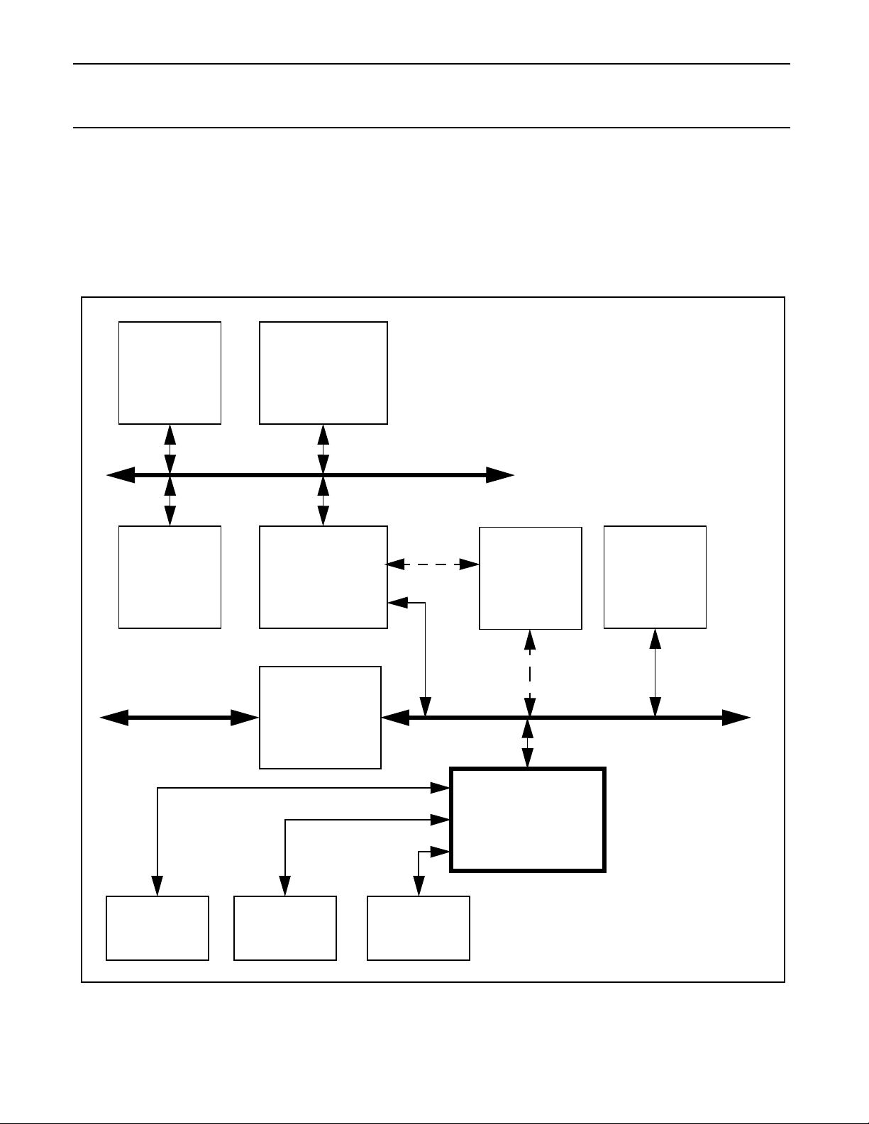
FIGURE 3 Block Diagram of a PC/AT System with the SAA7780
CPU
System
Bridge
TM
HOST BUS
AGP
Graphics
Cache
Memory
ISA BUS PCI BUS
Pentium
Controller
PCI to ISA
Multi I/O
AC97 CODEC
Serial DAC
1999 Sep 30 10
and/or
ThunderBirdTM Audio
Controller
JoystickMIDI Port

ThunderBird Q3D PCI Audio SAA7780
Philips Semiconductors
Product Specification
Accelerator
Systems that provide DDMA or have the ISA bridge on the primary PCI bus are able to perform SoundBlaster emulation
enabling the operation of legacy DOS based games. The SAA7780 chip provides two 8237 style DMA channels to
perform legacy DMA cycles on selected systems. The same two 8237 channels provide Distributed DMA support as
well. PC/PCI is also supported to provide legacy DMA support on chipsets that support said protocol.
DirectSound acceleration, both for 2D and 3D audio along with wavetable sample fetching, is accomplished using the
SAA7780 chip PCI 2.1 bus master. This bus master provides the means for the SAA7780 chip to accelerate
DirectSound audio streams as well as fetch wavetable samples for the 64 voice wavetable synthesis and effects
algorithms. Wavetable sample fetching is always retrieved from system memory saving the cost of an external
wavetable ROM. Downloadable sample sets, with software, are also supported using the bus master hardware.
Additionally, the SAA7780 chip follows the AC97 Architecture to provide high quality audio by the use of a separate
codec. Serial DACs, as well as an AC97 CODEC can be selected to provide audio into the analog world. A serial DAC
is used in case the system designer wishes to use an inexpensive playback converter and does not require a record
function. A codec and a DAC can be used if multi-channel audio is required.
The SAA7780 chip supports additional interfaces to sustain both required and optional features. These interfaces
include a standard 4-axis/4 button joystick, external MIDI port, an SRAM interface for external DSP code or enhanced
reverb, and a 16650 UART for an external modem.
The ActiMedia DSP runs the audio algorithms for wavetable synthesis, FM synthesis, special effects such as reverb
and chorus, along with sample rate conversion and data management. The imbedded DSP core and its peripherals are
managed solely by the DSP and require no intervention from the host. The DSP can pass messages to and from each
domain to provide a host software interface into the DSP domain.
Structural and Functional Overview
The SAA7780 contains components to implement the sound generation with accessories to add value to a gaming type
environment. In short, there are three basic types of blocks to implement all of the advanced features present in this
chip. The three types of blocks are PCI domain, DSP domain and mailbox. The PCI domain type of blocks refer to the
blocks that connect only to the internal and external PCI interfaces. The DSP domain blocks connected only to the DSP
code or data busses. The mailbox type interfaces between both worlds providing both functional and test operations
between the two domains. The following sections will give more details on the function and operation of each block.
PCI Interface, Configuration and Interrupt Serializer
The SAA7780 chip PCI interface is composed of master and slave state machines, an address/data/byte enable
datapath, a bus arbiter for the two on chip masters, control logic for the master and slave internal busses, an interrupt
serializer, and the standard PCI configuration register header.
The standard PCI configuration header is also supported. Since the SAA7780 is a multi-function device, there are three
PCI configuration spaces allocated for each function. The three functions are the audio device, the joystick and the
16650 UART. The purpose of the multiple configuration headers is to ensure PCI compliance and enable the operating
system to select the correct software driver for each individual device. The Serial CFG Port is used to shift in subvendor
specific data for each of the PCI configuration headers. The Serial CFG port is an industry standard I2CTM format. The
configuration headers are included in the PCI interface to reduce inter-block routing. All other PCI configuration space
registers are included in the blocks that utilize these registers.
16650 UART
In order to support an external hardware modem chip set, a 16650 UART is included in the SAA7780 chip. The 16650
UART excludes the need for an additional ISA based UART thereby reducing system costs. The 16650 UART resides
in I/O space and is re-mappable.
1999 Sep 30 11
ThunderBird Q3D PCI Audio SAA7780
Philips Semiconductors
Product Specification
Accelerator
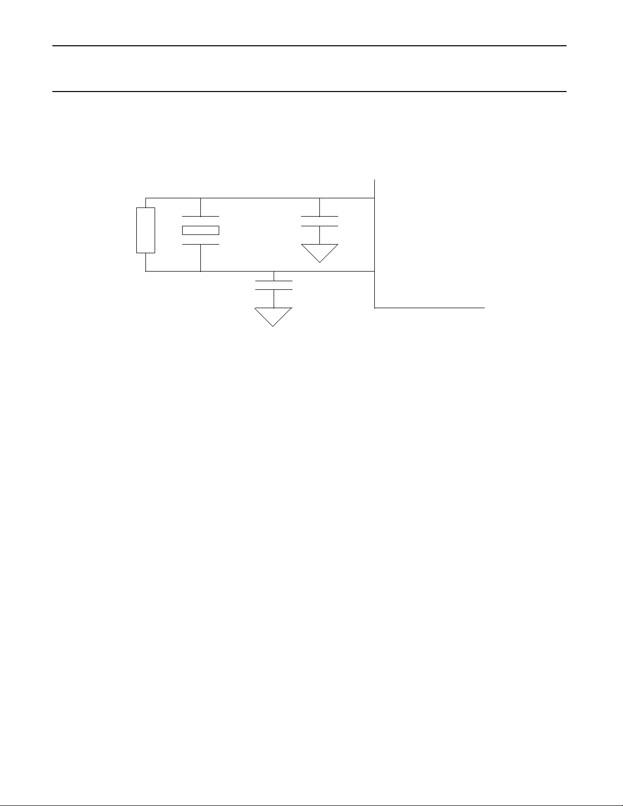
Clocks and the PLL Subsystem
Clocks for operation of the SAA7780 are derived from two sources; an external crystal and bit clock from the AC97
CODEC. The SAA7780 PLL Subsystem derives its reference from the external crystal.
FIGURE 4
xtalin
15pF
470k
The SAA7780 substem consists of a fixed layout PLL cell and a digital interface to the 8 bit PS bus. The PLL is
designed to drive the clocks for the DSP subsystem. The implementation calls for the PLL to be utilized with complete
programmable register interface to enable the tuning of the frequencies as necessary.
Multimedia Timer
The SAA7780 chip supplies a 20-bit, 1uS resolution timer for game synchronization. The timer data can be accessed as
an I/O device. This timer can be used by game developers to keep track of time elapsed to synchronize the video to the
audio stream. The timer can be polled or interrupt driven and is selectable by the user application.
DMA is for the Sound Blaster registers, the DSP Mastering Device (DMD), and the Audio codec. To cover as many
systems as possible, the DMA interface supports three modes for legacy support: Mobile PC/PCI DMA Arbitration
(PC/PCI), Distributed DMA (DDMA), and Legacy Accommodation Mode (LAM).
Legacy Accommodation Mode allows the SAA7780, in an architecturally compatible system, to snoop and snarf
selected DMA cycles on the PCI bus that were intended to the ISA Bridge. If a chip set supports Distributed DMA, the
SAA7780 will use this method since it is more efficient than LAM. Additionally, PC/PCI can be utilized as well if neither
DDMA nor LAM are supported on the selected chip set.
14.318MHz
15pF
SAA7780
xtalout
AC Link and the DSP Master Device Interface
The SAA7780 chip provides support for the AC97 specification by supplying an AC Link interface to communicate with
an industry standard AC97 CODEC. The AC Link interface is set up to allow the PCI, DMA and DSP busses to interface
with the AC97 codec via the AC Link. The AC Link is compliant with the release 1.03 of the AC97 specification.
Sound Blaster Registers
The other device that requires DMA is the SoundBlaster registers. DMA is used to transfer SoundBlaster digital audio
files from the host to a codec for playback in addition to providing a mailbox for other commands. In order for the DSP
to emulate the Sound Blaster sound effects, a legacy register set must be implemented to capture these commands.
These sixteen, 16-bit registers are used primarily to emulate SoundBlaster Pro register set as well as the SoundBlaster
1999 Sep 30 12

ThunderBird Q3D PCI Audio SAA7780
Philips Semiconductors
Product Specification
Accelerator
Pro mixer registers. These registers are used as a mailbox to the DSP data bus to deliver data to the SoundBlaster
Emulation code. The SAA7780 chip supports DMA to the Sound Blaster that legacy code requires. All data transmitted
over the SoundBlaster Registers is processed by the DSP to emulate the Sound Blaster Pro hardware.
OPL3 Registers and the FM Accelerator
The OPL3 register interface is a subset of the complete SoundBlaster register set. The OPL3 registers are separate to
point out that the FM legacy is supported at the register level. The OPL3 registers simply pass FM synthesis commands
to the SoundBlaster Emulation code and receive status from the same code.
Virtual Registers
The Virtual Registers interfaces the PCI bus and two substantial wavetable synthesis accelerators: the Sample Fetch
and Address Generation accelerators. The Virtual Registers is responsible for setting up the PCI interface for master
cycles data fetches and retrieving those fetches into a sample buffer. The Virtual Registers get commands from the
Address Generation accelerator and turns them into PCI master requests. Once the data has been retrieved, the Virtual
Register then instructs the Sample Fetch accelerator to process a block of data. Once the processing is complete, the
Sample Fetch Accelerator notifies the Virtual Registers that all is clear and that new data can be processed.
Address Generation Accelerator
The Address Generation accelerator is a preprocessing unit for the sample fetching mechanism inside the Virtual
Registers. The Address Generator will get a set of parameters from the DSP code on a per voice basis for either
DirectSound processing or wavetable synthesis. Once these voice parameters are set, the hardware is instructed to
translate the addresses and fetch the audio samples from system memory. The Address Generator is also capable of
looping with intervention from the DSP code. The DSP kills voices by instructing the Address Generator to stop fetching
data. Once the samples are fetched, they are stored in the Virtual Register’s input sample buffer for processing by the
Sample Fetch Accelerator.
Sample Fetch Accelerator
The Sample Fetch accelerator is used to process audio samples fetched by the Virtual Registers and deliver them to
the DSP code for further processing. This processing can include pitch shifting or rate conversion. The degree of pitch
shifting is under direction of DSP code indicating the Sample Fetch accelerator is programmable. The input samples
are taken from the Virtual Register’s input sample buffer and stored in DSP memory space.
MIDI Registers and UART
An MPU401 compatible UART is supplied to enable external MIDI devices to use the SAA7780 chip synthesizers as
well as its external device’s own synthesizer. The MIDI register interface is used to pass the MIDI command stream
from the host to the DSP firmware for parsing into synthesizer commands. The MPU401 UART always operates in
“dumb” mode. Both the PCI and DSP can access the MIDI UART directly. Data is presented from/to the MPU401
Registers in a mailbox fashion to the MPU401 UART.
Music DAC Interface
The music DAC interface allows for an inexpensive, high quality, playback of the final stereo mix or for providing the
unique QUAD feature when used in conjunction with the standard AC97 V1.03 CODEC. The interface is a standard
EIAJ format supporting many brands of inexpensive 16 bit DACs. The Music DAC interface is capable of playback
sample rates from 22.05 - 48.0 KHz.
1999 Sep 30 13

ThunderBird Q3D PCI Audio SAA7780
Philips Semiconductors
Product Specification
Accelerator
General Purpose Input/Output
There are five general purpose I/O pins that are controlled by the DSP. These pins can be used for power management
of external devices or for test and debug of DSP code. All are full time available under DSP code control. These GPIOs
are not controllable from the PCI bus and are generally not available to users.
PINE DSP Core
The Pine DSP core is a programmable 16-bit integer DSP with separate code and data busses (Harvard architecture).
Main features of the DSP core include 2K x 16 data RAM, 64K word code and data space, 16 x 16 bit two’s complement
parallel multiplier with 32-bit product, single cycle multiply/accumulate instructions, 36-bit ALU, two 36-bit accumulators,
six-general purpose 16-bit pointer registers, option for up to eight user-defined 16-bit registers, zero overhead looping,
repeat and block-repeat instructions with one nesting level, shifting capability, automatic saturation mode on overflow
while reading content of accumulators, divide and normalize step support.
As noted on Figure 1, the DSP subsystem is supported by two dedicated Pine internal busses called the DSP code bus
and the DSP data bus. All DSP peripherals are connected to the DSP data bus while the code bus is used for just that,
DSP code ROM and RAM. Both the DSP code and data busses are 16-bit for the address and data lines on each bus.
DSP code also enables the DSP core to act as a PCI bus master making it a powerful and flexible audio processing
unit.
DSP Interrupt Controller
The DSP Interrupt Controller is a programmable, priority encoded device that encodes two interrupt signals to the Pine
core. The DSP Interrupt Controller resides on the DSP data bus and is programmed by DSP code. Both sets of
interrupt vectors feature an enable and status bit for each interrupt based device.
DSP Memory Controller
The DSP memory controller provides controls and decodes for the regular DSP data and code RAMs as well as the
code ROMs. The Memory Controller also includes a patch mechanism to allow ROM code to be updated or fixed using
a trapping device.
Game Port
The SAA7780 Game Port interface is designed to emulate the PC-AT based legacy joystick operation as well as
support of a digital joystick mode. The legacy or analog, type of operation is designed to support all legacy software that
uses the original joystick address and the method for resolving the joystick axes positions. The Digital Mode is
designed to reduce the joystick overhead by resolving the joystick position directly and to support applications that use
DirectInput.
The legacy joystick used a one shot multi-vibrator on each of the four joystick potentiometers. These one shots were
set up to deliver a pulse that was proportional to the resistor value of the joystick potentiometers. Software would them
poll the one shots to see if they had been set to the original value. The time it took for each axes to return to the original
value was resolved into a position by the legacy software. The SAA7780 emulates the 558 based one shot circuit to
support legacy games that use the PC-AT joystick. The joystick button values were routed directly to the system bus
where only a decode was required to read the value of the button. Software would poll the buttons as well. All button
and joystick axes data is returned in a single byte wide register.
Game Port Legacy I/O Register
This register is the legacy mode register for the 558 based joystick. Typically, this register is located at legacy address
of 201h. Reads from this register will poll the status of the joystick buttons and are used to resolve the position. Writes
1999 Sep 30 14
ThunderBird Q3D PCI Audio SAA7780
Philips Semiconductors
Product Specification
Accelerator
to this register will discharge the external capacitors to emulate the 558 one shots. Software can then poll the joystick
register bit to resolve each of the joystick axes positions by timing. The joystick button register bits have meaning in
both the digital and analog modes. The axes bits are only valid for analog mode.
Game Port 558-Based Register - Gameport (RO) )
I/O GMBASE D7 D6 D5 D4 D3 D2 D1 D0
Offset 1h JOYB_2 JOYB_1 JOYA_2 JOYA_1 JOYB_Y JOYB_X JOYA_Y JOYA_X
POR Value 1 1 1 1 0 0 0 0
Bit Name R/W Function
7 JOYB_2 RO Joystick B button 2 status. The joystick buttons should be de-bounced and
de-glitched from the chip interface. The joystick button status registers are
cleared when the joystick button is pressed.
6 JOYB_1 RO Joystick B button 1 status.
5 JOYA_2 RO Joystick A button 2 status.
4 JOYA_1 RO Joystick A button 1 status.
3 JOYB_Y RO Joystick B y-coordinate. Can also be referred to as position 3.
2 JOYB_X RO Joystick B x-coordinate. Can also be referred to as position 2.
1 JOYA_Y RO Joystick A y-coordinate. Can also be referred to as position 1.
0 JOYA_X RO Joystick A x-coordinate. Can also be referred to as position 0.
SAA7780 Signal Definitions
PCI Local Bus Interface Signals
AD[31:0] 39,42,43,44,
45,46,48,49,
52,53,55,57,
59,61,63,64,
77,78,79,82,
83,85,86,87,
89,91,92,93,
94,95,97,98
IO-T PCI Address/Data
AD[31:0] contains a physical byte address during the first clock of a
PCI transaction, and data during subsequent clocks.
When the SAA7780 is a PCI master, AD[31:0] are outputs during
the address phase of a transaction. They are either inputs or outputs
during the data phase, depending on the type of PCI cycle in
process.
When the SAA7780 is a PCI slave, AD[31:0] are inputs during the
address phase. They are either inputs or outputs during the data
phase, depending on the type of PCI cycle in process.
1999 Sep 30 15

ThunderBird Q3D PCI Audio SAA7780
Philips Semiconductors
Product Specification
Accelerator
C/BE#[3:0] 50,65,76,88 IO-T PCI Bus Command and Byte Enables
C/BE#[3:0] defines the bus command during the first clock of a PCI
transaction, and the byte enables during subsequent clocks.
C/BE#[3:0] are outputs when the SAA7780 is a PCI bus master and
inputs when it is a PCI bus slave.
DEVSEL# 70 IO-STS PCI Bus Device Select
When the SAA7780 is a PCI bus master the SAA7780 uses
DEVSEL# to determine whether a master abort should occur if
DEVSEL# is not sampled active by clock 5 of the transaction, or to
determine whether a cycle is to be aborted or retried when a targetinitiated termination occurs.
When the SAA7780 is a PCI bus slave, DEVSEL# is an output
which the SAA7780 drives LOW during the second PCLK after
FRAME# assertion to the end of a transaction if the SAA7780 is
selected.
FRAME# 66 IO-STS PCI Bus Cycle Frame
When the SAA7780 is a PCI master, FRAME# is an output which
indicates the beginning of a SAA7780-initiated bus transaction.
While FRAME# is asserted data transfers continue. When FRAME#
is deasserted the transaction is in the final data phase.
When the SAA7780 is a PCI slave, FRAME# is an input that initiates
an I/O, memory or configuration register access if the SAA7780 is
selected for the transaction. The SAA7780 latches the C/BE#[3:0]
and AD[31:0] signals on the PCLK edge on which it first samples
FRAME# active.
IRDY# 67 IO-STS PCI Bus Initiator Ready
When the SAA7780 is a PCI master, IRDY# is an output which
indicates the SAA7780’s ability to complete the data phase of the
current transaction. It is always asserted from the PCLK cycle after
FRAME# is asserted to the last clock of the transaction.
When the SAA7780 is a PCI slave, IRDY# is an input which causes
the SAA7780 to hold-off completion of a read or write cycle until
sampled active.
STOP# 71 IO-STS PCI Bus Stop (Target Initiated Termination)
When the SAA7780 is a PCI master, STOP# is an input which
causes the SAA7780 to complete, abort or retry the transfer,
depending on the state of TRDY# and DEVSEL#.
When the SAA7780 is a PCI slave, it drives STOP# as active (LOW)
to terminate or retry a transaction.
1999 Sep 30 16

ThunderBird Q3D PCI Audio SAA7780
Philips Semiconductors
Product Specification
Accelerator
TRDY# 69 IO-STS PCI Bus Target Ready
When the SAA7780 is a PCI master, TRDY# is an input which
indicates the target agent’s ability to complete the data phase of the
transaction. After initiation of a PCI bus transaction, the SAA7780
inserts wait cycles until TRDY# is sampled active.
When the SAA7780 is a PCI slave, it drives TRDY# active to
indicate that the SAA7780 has sampled the data from AD[31:0]
during a write phase, or presented valid data on AD[31:0] during a
read phase.
PAR 75 IO-T PCI Bus Parity
When the SAA7780 is a PCI master, it drives PAR to reflect the
correct value for even parity on the AD[31:0] and C/BE#[3:0] buses
one clock after the address phase and after each write data phases.
When the SAA7780 is a PCI slave, it drives PAR to reflect the
correct value for even parity on the AD[31:0] and C/BE#[3:0] buses
one clock after completion of each read data phase.
PCREQ# 36 O-TS PC/PCI DMA Request
This signal requests DMA servies from en external chipset that
supports PC/PCI protocols. The SAA7780 chip asserts PCGNT#
according to the desired DMA channel required by either the
SoundBlaster or AC97 interfaces. The requested channel is
encoded serially on the PCGNT# pin.
The SAA7780 will become the bus owner when it receives an
asserted PCGNT# signal. This handshaking is synchronous to
PCLK.
PCGNT# 35 I-T PC/PCI DMA Grant
An asserted PCGNT# pin indicates that the external PC/PCI master
arbiter has granted DMA services to the the encoded DMA channel
to the requesting DMA agent on the SAA7780 chip.
REQ# 38 O-TS PCI Bus Request
This signal controls the PCI bus arbitration between the SAA7780
chip and the PCI master arbiter. When REQ# is asserted, the
SAA7780 indicates a desire to become the PCI bus owner. The
SAA7780 will become the bus owner when it receives an asserted
grant signals (GNT# is LOW). This handshaking is synchronous to
PCLK.
REQ# is three-stated while RST# is active.
1999 Sep 30 17

ThunderBird Q3D PCI Audio SAA7780
Philips Semiconductors
Product Specification
Accelerator
GNT# 37 I-T PCI Bus Grant
An asserted GNT# pin indicates that the PCI master arbiter has
granted bus ownership to the SAA7780 chip.
IRQSER 32 IO-OD PCI Bus Serial Interrupts
This pin is used to output the serial interrupt stream for legacy
interrupts. It is used only if the SAA7780 is used in a Common
Architecture system. Otherwise it is tri-stated.
INTA# 31 IO-OD PCI Bus Interrupt A
The interrupt output is a PCI compatible active low level sensitive
interrupt. It is only used if the SAA7780 is used in a non Common
Architecture system. Otherwise it is tri-stated. It is driven low when
any of the internal interrupts are asserted.
PERR# 72 IO-STS PCI Bus Parity Error
This signal indicates a data parity error for any cycle type other than
a Special Cycle command. PERR# is made active two clocks after
the completion of the data phase which caused the parity error. This
error signal may result in the generation of a non-maskable interrupt
(NMI) or other high priority interrupt sent to the CPU.
SERR# 73 IO-OD PCI Bus System Error
This signal indicates an address parity error, data parity errors on
Special Cycle commands or any other catastrophic system error.
SERR# is an open-drain bidirectional pin which is driven low for a
single PCLK cycle by the agent reporting the error. This error may
result in the generation of a non-maskable interrupt (NMI) or other
high priority interrupt sent to the CPU.
IDSEL 51 I-T Initialization Device Select
IDSEL is used as a chip select during configuration register read
and write operations. One system board address line from
AD[31:11] is used as IDSEL to select the SAA7780 configuration
space in the SAA7780 chip when used on the PCI bus.
CLKRUN# 100 O-OD PCI Bus Clock Run Request
The SAA7780 uses CLKRUN# according to the Mobile PCI protocol
to start the PCI clock or keep the clock running whenever an internal
PCI device requires it.
1999 Sep 30 18

ThunderBird Q3D PCI Audio SAA7780
Philips Semiconductors
Product Specification
Accelerator
PCLK 34 I-T PCI Bus Clock Input
PCLK is the PCI bus clock input. It is used to synchronize all PCI
bus operations and typically runs at 33MHz.
RST# 33 I PCI Bus Reset
An active low version of the system reset, this signal causes the PCI
interface to return to the idle states in all state machines and
asynchronously three-states all PCI bus signals. All registers will be
reset to their default values as well. The CODEC interface line
should be all driven inactive along with the external memory
interface. This reset will assert the DSP reset.
Serial Configuration Port
CFGDAT 101 I,PU-T Serial Configuration Data
This pin is used to shift in PCI configuration data for the Subsystem
ID and the Subsystem Vendor ID in each of the PCI configuration
headers present in the SAA7780 chip. The Serial Configuration Port
is a standard I2C interface. This line should never be pulled low.
CFGCLK 102 O-T Serial Configuration Clock
The serial clock is a 400 KHz clock generated from OSC and
supplied to an external serial EEPROM to synchronize the serial
configuration data.
Test Interface
TRI# 29 I-T Tri-State Test Enable
When this pin is pulled low and RST# is pulsed asserted, all output
and I/O pins of the SAA7780 will be forced into a three-state
condition. Pulsed assertion of the RST# signal will release the
SAA7780 from this test mode.
NAND# 30 I-T NAND Tree Test Enable
When this pin is pulled low and RST# is pulsed asserted, the
SAA7780 will enter the parametric NAND tree test mode. The
details of the NAND tree test mode are described later in this
document.
1999 Sep 30 19

ThunderBird Q3D PCI Audio SAA7780
Philips Semiconductors
Product Specification
Accelerator
16650 UART Interface
RXD 146 I-T UART Serial Data Input
This pin provides the serial bit stream to the 550-compatible UART.
This input is ignored when the Loop Mode is enabled.
TXD 145 O-T UART Serial Data Output
This pin is an output from UART, providing the serial bit stream to
external buffers or devices. This signal is forced high whenever the
transmitter is disabled, RST# is asserted, the transmit register is
empty, or the UART is in the Loop Mode.
RTS# 148 O-T UART Request To Send
An active low output that is the inverted value of the Modem Control
Register (MCR) bit 1, as follows:
When MCR[1] = 1, RTS# is low.
When MCR[1] = 0, RTS# is high.
When RST# is asserted, RTS# is forced high.
DTR# 149 O-T UART Data Terminal Ready
An active low output that is the inverted value of the Modem Control
Register bit 0, as follows:
When MCR[0] = 1, DTR# is low.
When MCR[0] = 0, DTR# is high.
When RST# is asserted, DTR# is forced high.
CTS# 150 I-T UART Clear To Send
The status of this input can be determined by reading bit 4 of the
Modem Status Register. When MSR[4] is read, it will be the inverted
value of CTS#. A change in status of CTS# sets the Delta CTS bit in
the Modem Status Register.
If the CTS# line changes state while the modem status interrupts
are enabled, an interrupt packet will be generated.
DSR# 151 I-T UART Data Set Ready
The status of this input can be determined by reading bit 5 of the
Modem Status Register. When MSR[5] is read, it will be the inverted
value of DSR#. A change in status of DSR# sets the Delta DSR bit
in the Modem Status Register.
If the DSR# line changes state while the modem status interrupts
are enabled, an interrupt will be generated.
1999 Sep 30 20

ThunderBird Q3D PCI Audio SAA7780
Philips Semiconductors
Product Specification
Accelerator
DCD# 152 I-T UART Data Carrier Detect
The status of this input can be determined by reading bit 7 of the
Modem Status Register. When MSR[7] is read, it will be the inverted
value of DCD#. A change in status of DCD# sets the Delta DCD bit
in the Modem Status Register.
If the DCD# line changes state while the modem status interrupts
are enabled, an interrupt will be generated.
RI# 153 I-T UART Ring Indicator
The status of this input can be determined by reading bit 6 of the
Modem Status Register. When MSR[6] is read, it will be the inverted
value of RI#. Bit 2 (TERI) of the Modem Status Register indicates
whether the RI# input signal has changed from a low to a high, since
the previous reading of the Modem Status Register.
If modem status interrupts are enabled when MSR[6] changes from
a 1 to a 0, an interrupt will be generated.
Joystick/Game Port
JACX 9 I/O-C,S Joystick A X Axis
Joystick A X-position.
JACY 13 I/O-C,S Joystick A Y Axis
Joystick A Y-position.
JBCX 10 I/O-C,S Joystick B X Axis
Joystick B X-position.
JBCY 12 I/O-C,S Joystick B Y Axis
Joystick B Y-position.
JAB[2:1] 7 I-T Joystick A Button Interface
Joystick A buttons. These buttons are internally de-bounced and deglitched using a low speed clock and metastable hardened flip-flops.
JBB[2:1] 14 I-T Joystick B Button Interface
Joystick B buttons. These buttons are internally de-bounced and deglitched using a low speed clock and metastable hardened flip-flops.
1999 Sep 30 21
 Loading...