

Philips saa7740h DATASHEETS

INTEGRATED CIRCUITS
DATA SH EET
SAA7740H
Digital Audio Processing IC
(DAPIC)
Product specification
Supersedes data of 1996 Mar 11
File under Integrated Circuits, IC01
1997 May 30
Philips Semiconductors Product specification
Digital Audio Processing IC (DAPIC) SAA7740H
FEATURES
Hardware
• Two digital inputs and two digital outputs in the I
format (i.e. 4 audio channels)
• Independent input/output interfaces
• Slave input/output interfaces
• Slave processing
• I2C-bus microcontroller interface
• DC filtering at the inputs
• One programmable 2nd-order digital filter unit
• Two multiply accumulate processor units
(24 × 16-bit/MAC)
• DRAM interface and address computation unit for
external delay lines
• On-chip coefficient and external delay line address
storage
• Hardware controlled soft mute via the MUTE pin
• Hardware controlled soft demute via the RST pin
• Operating ambient temperature; −40 to +85 °C.
Software
2
S-bus
• External delay line processing for delays up to 1 second
• Reverberation with selectable reverberation time (up to
5 seconds) and energy
• Three different surround sound programs to obtain a
spatial effect on 4 loudspeakers
• Passive DOLBY surround processing with the addition
of an external dynamic noise reduction IC
• Karaoke processing
• Dual 16th-order correction filtering
• Quad 8th-order correction filtering
• Digital volume and balance control
• Soft controlled soft mute/demute via the microcontroller
interface
• Input switching matrix
• Output rear and front switching matrix.
• 5-band parametric equalizer with selectable centre
frequency, slope setting and boost/cut gain settings
from −12 to +12 dB
• Stereo width control from mono to stereo to spatial
stereo
• Stereo Hall-effects for field acoustics, such as concert
halls, with 8 coefficients and 8 delayed taps per channel
APPLICATIONS
• Digital amplifiers
• Audio combination sets
• Car audio systems
• TV audio channels.
QUICK REFERENCE DATA
SYMBOL PARAMETER CONDITIONS MIN. TYP. MAX. UNIT
V
DD(tot)
I
DD(tot)
f
xtal
P
tot
T
amb
total DC supply voltage all VDD pins 4.5 5.0 5.5 V
total DC supply current f
= 16.9344 MHz − 60 − mA
xtal
input crystal frequency 12.288 16.9344 23.0 MHz
total power dissipation f
= 16.9344 MHz − 0.3 − W
xtal
operating ambient temperature −40 − +85 °C
ORDERING INFORMATION
TYPE
NUMBER
NAME DESCRIPTION VERSION
SAA7740H QFP64 plastic quad flat package; 64 leads (lead length 1.95 mm); body
PACKAGE
SOT319-2
14 × 20 × 2.8 mm
1997 May 30 2

Philips Semiconductors Product specification
Digital Audio Processing IC (DAPIC) SAA7740H
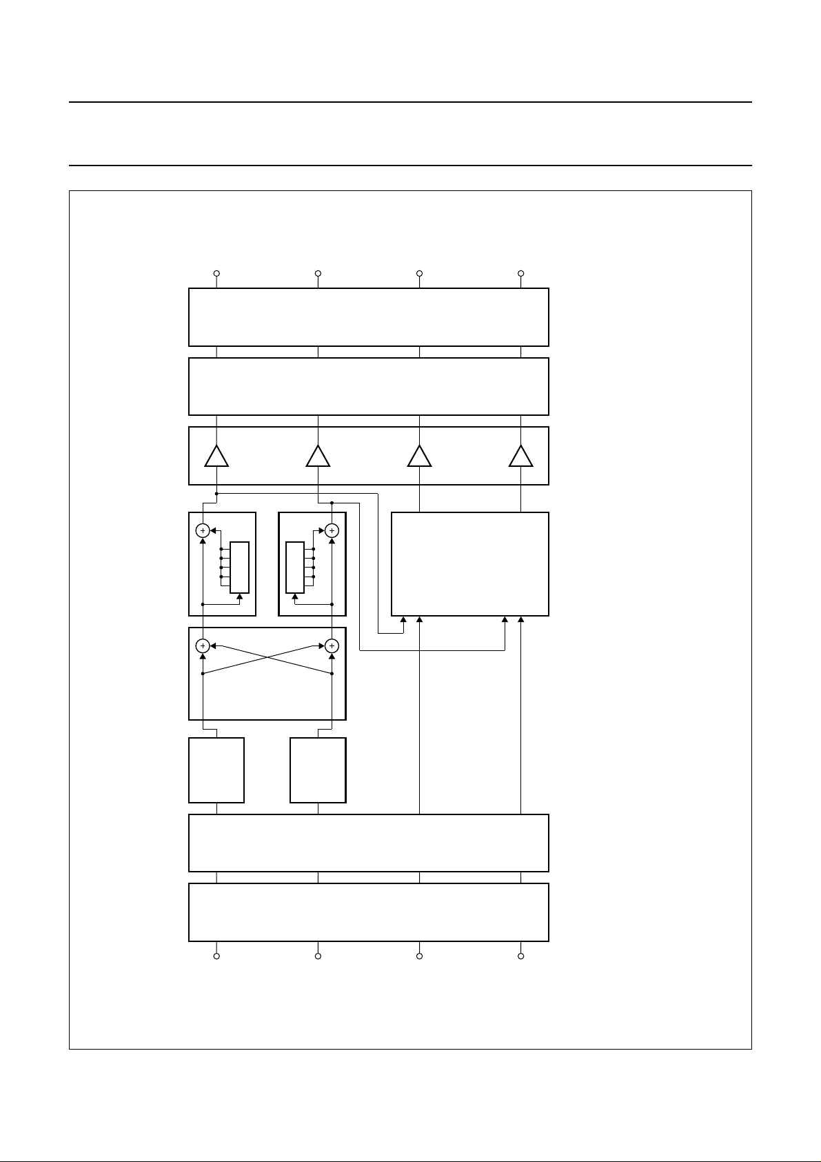
BLOCK DIAGRAM
handbook, full pagewidth
CLK1/XTAL1
XTAL2
SCCLK
DIWS
DI1D
DI2D
DIBCK
RST
ALL
V
DDXVSSX
56
59
OSCILLATOR
62
43
41
2
I S-BUS
42
44
1
64
PROGRAM
COUNTER
XTAL
INPUT
PROGRAMMABLE
SAA7740H
COUNTER
INPUT
BUFFER
ROM
CLKO
CLOCK
16
TSTCLK
636160
45
DIGITAL SIGNAL
PROCESSING CORE
2nd-ORDER FILTER
OFFSET FILTER
REGISTERS
7
COEFFICIENT
AS152AS2
TST147TST248TST3
MAC
16
RAM
16
2
I C-BUS
INTERFACE
51
49
OUTPUT
BUFFER
ADDRESS
CONTROL
UNIT
9, 13, 25, 40,
46, 50, 55
7
7, 8, 26, 32,
38, 53, 54
7
36
2
I S-BUS
OUTPUT
31 to 27/24 to 21
11, 12, 15, 16
34
35
37
19
10
17
18
14
20
33
MLC173
V
SS
V
DD
DOWS
DO1D
DO2D
DOBCK
4
MUTE
RAS
CAS
CAS2
WE
OE
A0 to A8
D0 to D3
A8B
MUX
2
SCL
3
SDA
Fig.1 Block diagram.
1997 May 30 3
Philips Semiconductors Product specification
Digital Audio Processing IC (DAPIC) SAA7740H
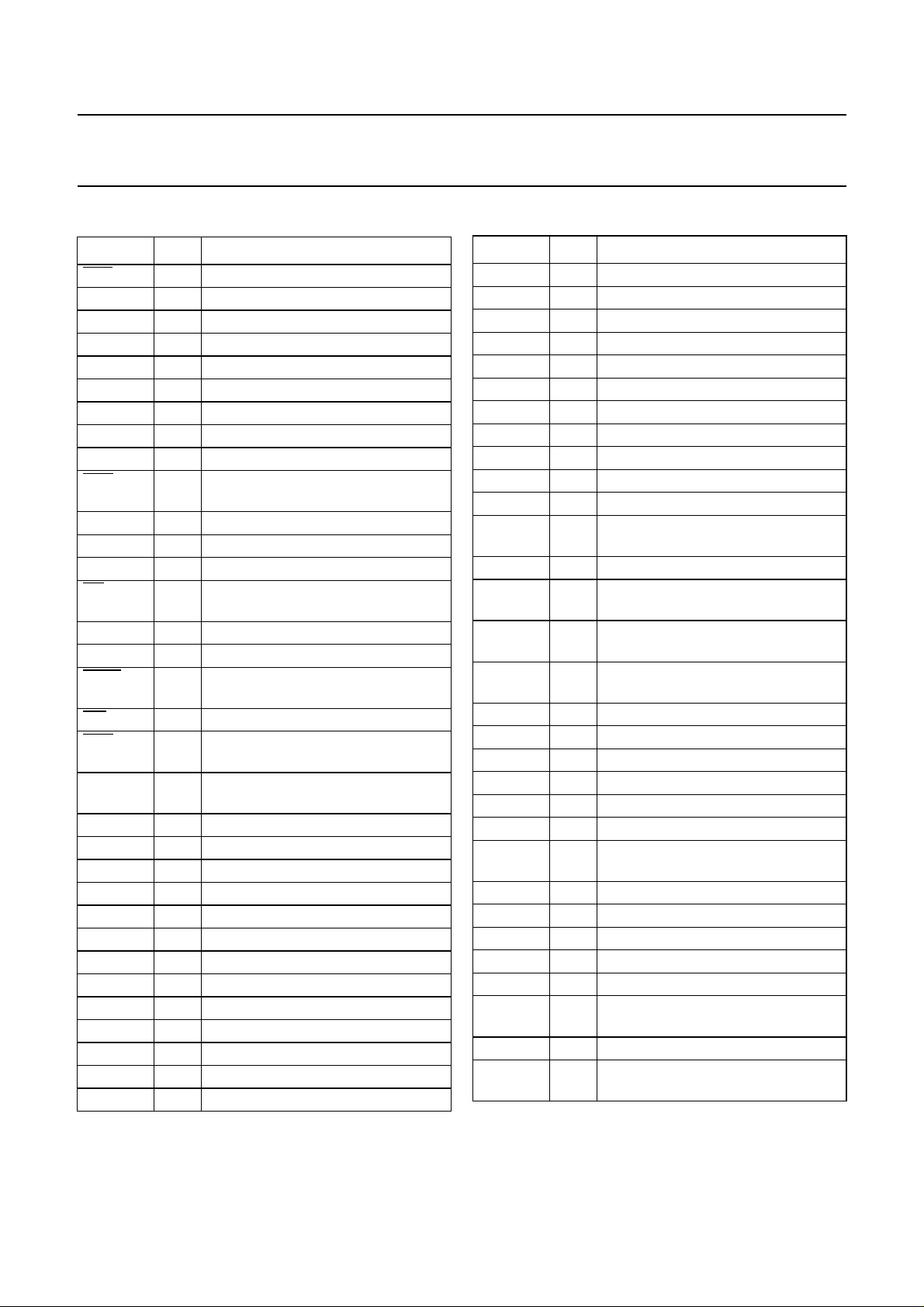
PINNING
SYMBOL PIN DESCRIPTION
RST 1 reset input (active LOW)
SCL 2 serial clock input (I
SDA 3 serial data input/output (I
2
C-bus)
2
C-bus)
MUTE 4 mute input (active HIGH)
n.c. 5 not connected
n.c. 6 not connected
V
DD
V
DD
V
SS
7 supply voltage
8 supply voltage
9 ground supply
CAS 10 column address strobe (DRAM)
(active LOW)
D0 11 input/output data bus line 0 (DRAM)
D1 12 input/output data bus line 1 (DRAM)
V
SS
13 ground supply
OE 14 output buffer enable (DRAM)
(active LOW)
D2 15 input/output data bus line 2 (DRAM)
D3 16 input/output data bus line 3 (DRAM)
CAS2 17 second column address strobe
(active LOW)
WE 18 write enable (DRAM; active LOW)
RAS 19 row address strobe (DRAM;
active LOW)
A8B 20 inverse MSB address line output
(DRAM)
A8 21 address line output 8 (DRAM)
A7 22 address line output 7 (DRAM)
A6 23 address line output 6 (DRAM)
A5 24 address line output 5 (DRAM)
V
SS
V
DD
25 ground supply
26 supply voltage
A4 27 address line output 4 (DRAM)
A3 28 address line output 3 (DRAM)
A2 29 address line output 2 (DRAM)
A1 30 address line output 1 (DRAM)
A0 31 address line output 0 (DRAM)
V
DD
32 supply voltage
MUX 33 address latch strobe output (SRAM)
SYMBOL PIN DESCRIPTION
DO1D 34 digital audio output 1 (I2S-bus)
DO2D 35 digital audio output 2 (I
2
S-bus)
DOWS 36 digital audio input word select
DOBCK 37 digital audio input serial bit clock
V
DD
38 supply voltage
n.c. 39 not connected
V
SS
DI1D 41 digital audio input 1 (I
DI2D 42 digital audio input 2 (I
40 ground supply
2
S-bus)
2
S-bus)
DIWS 43 digital audio input word select
DIBCK 44 digital audio input serial bit clock
TSTCLK 45 clock input for test mode
(should be tied LOW)
V
SS
46 ground supply
TST1 47 test pin input 1
(should be tied LOW)
TST2 48 test pin input 2
(should be tied LOW)
TST3 49 test pin input 3
(should be tied LOW)
V
SS
AS1 51 address select input 1 (I
AS2 52 address select input 2 (I
V
DD
V
DD
V
SS
CLK1/
50 ground supply
53 supply voltage
54 supply voltage
55 ground supply
56 clock or crystal input
2
C-bus)
2
C-bus)
XTAL1
n.c. 57 not connected
n.c. 58 not connected
XTAL2 59 crystal output 2
V
V
DDX
SSX
60 crystal supply voltage
61 crystal ground supply
SCCLK 62 scan test clock input
(should be tied LOW)
CLKO 63 clock signal output
ALL 64 mode select input
(should be tied HIGH)
1997 May 30 4
Philips Semiconductors Product specification
Digital Audio Processing IC (DAPIC) SAA7740H
handbook, full pagewidth
RST
SCL
SDA
MUTE
n.c.
n.c.
V
DD
V
DD
V
SS
CAS
D0
D1
V
SS
OE
D2
D3
CAS2
ALL
CLKO
64
63
1
2
3
4
5
6
7
8
9
10
11
12
13
14
15
16
17
SCCLK
62
SSX
V
61
XTAL2
V
60
59
SAA7740H
n.c.
58
n.c.
57
DDX
SS
CLK1/XTAL1
V
56
55
DD
DD
V
54
AS2
V
53
52
AS1
51
V
50
SS
49
TST3
TST2
48
TST1
47
V
46
SS
TSTCLK
45
DIBCK
44
DIWS
43
DI2D
42
DI1D
41
V
40
SS
n.c.
39
V
38
DD
DOBCK
37
DOWS
36
DO2D
35
WE
18
RAS
19
20
21
A8B
A8
22
A7
A6
24
23
A5
V
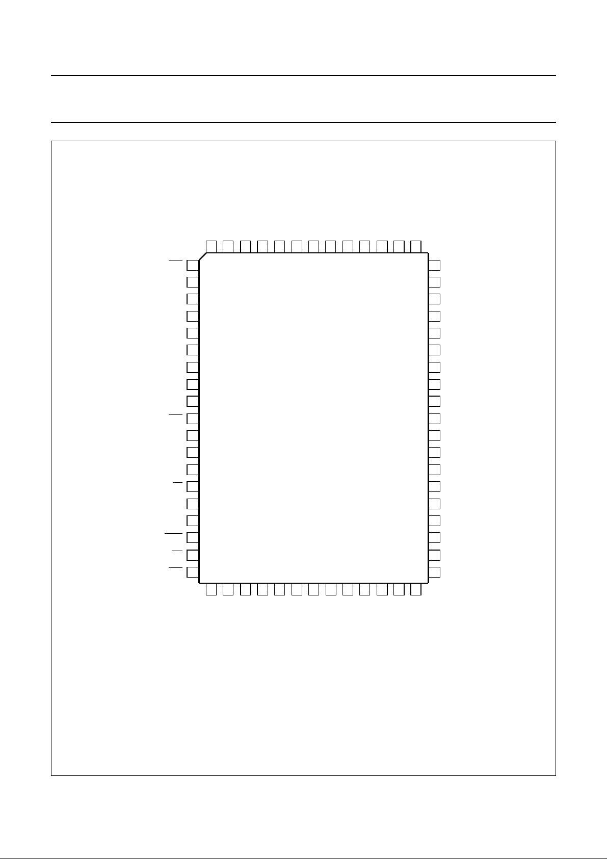
Fig.2 Pin configuration.
1997 May 30 5
25
SS
V
26
DD
A4
DO1D
34
MUX
33
27
28
29
30
31
A3
A2
A1
A0
MLC156
32
DD
V

Philips Semiconductors Product specification
Digital Audio Processing IC (DAPIC) SAA7740H
GENERAL DESCRIPTION
The SAA7740H is a function-specific digital signal
processor. The device is capable of performing processing
for listening-environments such as equalization,
hall-effects, reverberation, surround-sound and digital
volume/balance control. The SAA7740H can also be
reconfigured (in a dual and quad filter mode) so that it can
be used as a digital filter with programmable
characteristics.
For reasons of silicon efficiency, the SAA7740H realises
most functions directly in hardware. The flexibility exists in
the possibility to download function parameters, correction
coefficients and various configurations from a host
microcontroller (see Fig.1). The parameters can be
passed in real time and all functions can be switched on
simultaneously.
The communication with a host microcontroller conforms
with the standard I
2 digital stereo signals in the I2S-bus format at audio
sampling frequency (fas) and provides 2 digital stereo
outputs.
Mode description
The SAA7740H can be set in four basic modes of
operation.
2
C-bus format. The SAA7740H accepts
ENERAL DAPIC MODE
G
In the general DAPIC mode two variants are available
(see Figs 3 and 4). In this mode the DAPIC accepts
2 stereo input signals. DC filtering is performed on the
inputs before further processing. On one of the stereo
inputs a 5-band graphic equalization can be performed.
The stereo image of this signal can be controlled from
mono to stereo.
In the first variant (see Fig.3) a stereo hall-effect can be
added to the signal by means of direct reflections. In the
second variant (see Fig.4) a reverberation effect can be
added to the signal by means of exponential decaying
reflections. Surround-sound can then be created for the
rear loudspeakers. The surround-sound module is also
able to provide karaoke.
The surround-sound module accepts the second stereo
input, a microphone signal can be added via the 5-band
equalizer. At the output, each of the 4 channels can be
individually delayed via the external DRAM.
The interfacing and addressing of the DRAM is performed
by the DAPIC.
The applications for the general mode are digital
amplifiers, audio combination sets and TV audio channels.
1997 May 30 6
Philips Semiconductors Product specification
Digital Audio Processing IC (DAPIC) SAA7740H
MLC151
SWITCHES
(1)
DELAY
VOLUME/
BALANCE
(1)
5 - BAND
GRAPHIC
EQUALIZER
(1)
DELAY
STEREO
(1)
(1)
hall effect
DELAY
CONTROL
5 - BAND
GRAPHIC
EQUALIZER
DC
FILTERS
(1)
OR
SOUND
KARAOKE
SURROUND
handbook, full pagewidth
Fig.3 General DAPIC mode with hall-effect.
SWITCHES
1997 May 30 7
(1) External DRAM.

Philips Semiconductors Product specification
Digital Audio Processing IC (DAPIC) SAA7740H
MLC152
SWITCHES
(1)
DELAY
VOLUME/
BALANCE
(1)
5 - BAND
GRAPHIC
generator
reverberation
STEREO
CONTROL
EQUALIZER
(1)
5 - BAND
GRAPHIC
EQUALIZER
DC
FILTERS
(1)
OR
SOUND
KARAOKE
SURROUND
handbook, full pagewidth
Fig.4 General DAPIC mode with reverberation.
SWITCHES
1997 May 30 8
(1) External DRAM.

Philips Semiconductors Product specification
Digital Audio Processing IC (DAPIC) SAA7740H
DUAL-FILTER MODE
In the dual-filter mode one mono signal is accepted
(see Fig.5) The input can be selected from either one of
the 2 stereo inputs (from the left or right input channel).
DC filtering is performed at the input before further
processing. Two separate corrections, in parallel, can be
performed by means of an 8-band graphic equalizer.
handbook, full pagewidth
DC
FILTERS
16 POLE/ZERO
CORRECTION
FILTER
16 POLE/ZERO
CORRECTION
FILTER
16 poles and 16 zeros can be selected arbitrarily from the
Z-domain. At the output, one of the channels can be
delayed internally by the DAPIC. The two corrected
outputs can be added to either one of the two stereo
outputs.
The application for this mode is in loudspeaker correction.
FIXED
DELAY
11 SAMPLES
SWITCHES
SWITCHES
MLC153
Fig.5 Dual filter mode.
1997 May 30 9
 Loading...