


INTEGRATED CIRCUITS
DATA SH EET
SAA4963
Integrated NTSC comb filter
Preliminary specification
Supersedes data of 1996 Nov 22
File under Integrated Circuits, IC02
1997 Mar 03
Philips Semiconductors Preliminary specification
Integrated NTSC comb filter SAA4963
FEATURES
• One chip NTSC comb filter
• Time discrete but continuous amplitude signal
GENERAL DESCRIPTION
The SAA4963 is an alignment-free one chip comb filter
compatible with NTSC M systems.
processing with analog interfaces
• Internal delay lines, filters, clock processing and signal
switches
• Alignment-free
• Few external components.
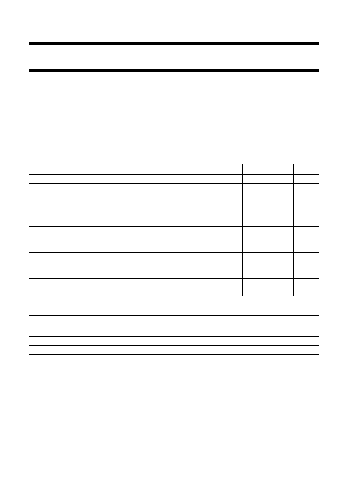
QUICK REFERENCE DATA
SYMBOL PARAMETER MIN. TYP. MAX. UNIT
V
CCA
V
DDD
V
CCO
V
CCPLL
I
CCO
I
DDD
I
CCA
I
CCPLL
V
13(p-p)
V
14(p-p)
V
7(p-p)
V
1(p-p)
V
11(p-p)
V
9(p-p)
analog supply voltage 4.75 5 5.5 V
digital supply voltage 4.75 5 5.5 V
analog supply voltage output buffer 4.75 5 5.5 V
analog supply voltage PLL 4.75 5 5.5 V
analog supply current output buffer − 35 45 mA
digital supply current − 36mA
analog supply current − 10 17 mA
analog supply current PLL − 1.5 2.5 mA
CVBS input signal (peak-to-peak value) 0.7 1 1.4 V
luminance input signal (peak-to-peak value) 0.7 1 1.4 V
chrominance input signal (peak-to-peak value) − 0.7 1 V
subcarrier input signal (peak-to-peak value) 100 200 400 mV
luminance output signal (peak-to-peak value) 0.6 1 1.54 V
chrominance output signal (peak-to-peak value) − 0.7 1.1 V
ORDERING INFORMATION
TYPE
NUMBER
SAA4963 DIP20
SAA4963T SO20
NAME DESCRIPTION VERSION
plastic dual in-line package; 20 leads (300 mil)
plastic small outline package; 20 leads; body width 7.5 mm
1997 Mar 03 2
PACKAGE
SOT146-1
SOT163-1

Philips Semiconductors Preliminary specification
Integrated NTSC comb filter SAA4963
BLOCK DIAGRAM
+5 V
+5 V
handbook, full pagewidth
+5 V
+5 V
CL3
HSEL
O
C
9
CCOMB
LPFO20.5−1
BPF
BPF
1H DELAY
LPFI
LINES
S2B
i.c.
19
CONT1
CL3
CL3
CL3
CL3
HSEL
CONT2
SAA4963
CHROMACOMB
3
MHA558
i.c.
Fig.1 Block diagram.
O
Y
11
100 nF
A
CONT1
CL3
1H DELAY
STOPS
−0.5
BPF
LINES
CL3
20 10
100 nF
100 nF
100 nF
100 nF
100 nF
REFBP REFDL
47 Ω
DDD
V
16 15
DGND
CCO
V
OGND
86
CCA
V
AGND
54
CCPLL
V
17 18
PLLGND
A
100 µF
D
100 µF
A
100 µF
A
100 µF
A
VOLTAGE
REFERENCE
CURRENT
REFERENCE
CONT1
CONT2
LPF
CONTROL
LPFO1
HSEL
CL3
CL3
LUMACOMB
STOPS
CL3
DET
H
DET
V
S2A
YCOMB
LPFO1
DELAY
COMPENSATION
DET
A
D
V
DET
H
1
FSC
CLOCK
CONTROL
2
SVHS
SYNC
12
CSY
A
SEPARATOR
330 nF
1997 Mar 03 3
CLAMP
STOPS
14
ext
Y
330 nF
13
CVBS
330 nF
BIAS
ext 7
C
100 nF
Remark: all switches in LOW position.
Philips Semiconductors Preliminary specification
Integrated NTSC comb filter SAA4963
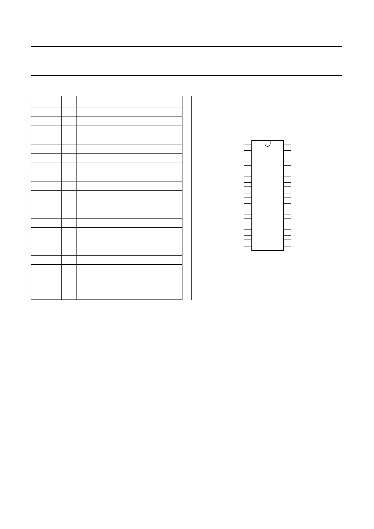
PINNING
SYMBOL PIN DESCRIPTION
FSC 1 subcarrier frequency input
SVHS 2 SVHS mode forcing
i.c. 3 internally connected
V
CCA
AGND 5 analog ground
V
CCO
C
ext
OGND 8 analog ground output buffer
C
O
REFDL 10 decoupling capacitor for delay lines
Y
O
CSY 12 storage capacitor
CVBS 13 CVBS input signal
Y
ext
V
DDD
DGND 16 digital ground
PLLGND 17 analog ground PLL
V
CCPLL
i.c. 19 internally connected
REFBP 20 decoupling capacitor for band-pass
4 analog supply voltage
6 analog supply voltage output buffer
7 external chrominance input
9 chrominance output signal
11 luminance output signal
14 external luminance input
15 digital supply voltage
18 analog supply voltage PLL
filter reference
handbook, halfpage
FSC
1
SVHS
2
i.c.
3
V
4
CCA
AGND
5
V
CCO
C
ext
OGND
C
REFDL
SAA4963
6
7
8
9
O
10
MHA559
Fig.2 Pin configuration.
20
19
18
17
16
15
14
13
12
11
REFBP
i.c.
V
CCPLL
PLLGND
DGND
V
DDD
Y
ext
CVBS
CSY
Y
O
1997 Mar 03 4

Philips Semiconductors Preliminary specification
Integrated NTSC comb filter SAA4963
FUNCTIONAL DESCRIPTION
Functional requirements
The NTSC comb filter processes the video standard
NTSC M. For SVHS signals the input signals are
bypassed to the output without processing by selecting the
SVHS mode.
A sync separation circuit is incorporated to generate
control signals for the internal clock processing. With a
sync compression of up to 12 dB (see Fig.5) the sync
separator works properly.
The IC is controlled via the pin SVHS (pin 2) which forces
the IC into the SVHS mode (bypass) if the comb filter
function is not desired. It is possible to select the following
modes:
COMB-mode: Luminance and chrominance comb filter
function active, if SVHS mode not active
SVHS-mode: No IC function active, all clocks inactive,
(pin 7) is bypassed to CO (pin 9) and Y
C
ext
(pin 14) is
ext
bypassed to YO (pin 11). This mode is forced via SVHS
(pin 2).
The mode changes from SVHS to COMB and vice versa
are always performed asynchronously with respect to the
vertical blanking interval.
Pin description
PIN 1)
FSC (
Input for the reference frequency fsc (see note 3 of Chapter
“Characteristics”). For SVHS signals the signal
performance can be increased by switching the input
signal at FSC off.
SVHS (
PIN 2)
Input signal that controls the operation mode. An internal
low-pass filter suppresses the subcarrier frequencies.
Thus applications are supported where the operation
mode (COMB or SVHS) is controlled by the DC level of the
FSC input signal at pin 1. For those applications the SVHS
input can be externally connected to FSC (pin 1).
The PLL and the clock processing are always stopped if
the selected level for SVHS is applied to SVHS
(independent of the vertical pulse).
V
CCA,VCCO,VDDD
AND V
(PINS 4, 6, 15 AND 18)
CCPLL
Supply voltages.
AGND, OGND, DGND
AND 17)
16
AND PLLGND (PINS 5, 8,
Ground connection. AGND is used as signal reference for
all analog input and output signals.
C
(PIN 7)
ext
Input for an external chrominance signal which is
correlated with the external VBS signal in SVHS-mode.
(PIN 9)
C
O
Chrominance output signal. This output delivers the comb
filtered chrominance from the CVBS signal in
COMB-mode or the external chrominance signal from the
input C
if the IC is forced into the SVHS-mode.
ext
In COMB-mode the output is delayed by an additional
processing delay.
Table 2 C
MODE C
output signal
O
OUTPUT SIGNAL
O
COMB comb filtered chrominance signal
SVHS external chrominance signal from C
REFDL (
PIN 10)
ext
input
Decoupling capacitor for the delay line reference voltage.
Y
(PIN 11)
O
VBS output signal. This output delivers the comb filtered
luminance signal (including synchronization pulses) in
COMB-mode or the external (C)VBS signal from the input
Y
if the IC is forced into SVHS-mode. In COMB-mode
ext
the output is delayed by an additional processing delay.
Table 1 SVHS function
SVHS SELECTED MODE
LOW COMB
HIGH SVHS (PLL and clock processing stopped)
1997 Mar 03 5
Table 3 Y
MODE Y
output signal
O
OUTPUT SIGNAL
O
COMB comb filtered luminance signal
SVHS external (C)VBS signal from Y
ext
input

Philips Semiconductors Preliminary specification
Integrated NTSC comb filter SAA4963
CSY (PIN 12)
Sync top capacitor for the sync separator.
CVBS (
PIN 13)
Input for the CVBS signal in COMB-mode.
(PIN 14)
Y
EXT
Input for an external luminance signal in SVHS-mode.
REFBP (
PIN 20)
Decoupling capacitor for the band-pass filter reference
voltage.
Internal functional description
WITCHED CAPACITOR DELAY LINE
S
Delays the CVBS input signal by 1 line. Input signals for
the delay lines are the CVBS signal, the clock CL3 (3 × fsc)
and the control signal HSEL.
Output signals are the non-delayed and the 1-line delayed
CVBS signal.
WITCHED CAPACITOR BAND-PASS FILTERS (BPFS)
S
L
OW-PASS FILTER INPUT (LPFI)
Analog input low-pass filter to reduce the outband
frequencies of EMC. The input low-pass filter is included in
the signal path.
OW-PASS FILTER OUTPUTS (LPFO1 AND LPFO2)
L
Two different types of output low-pass filters LPFO1 and
LPFO2 are necessary to get equal signal delays within the
luminance path and the chrominance path (important for
good transient behaviour). The low-pass output filter type
LPFO1 is used for the luminance output while LPFO2 is
used for the chrominance output. The filters are analog 3rd
order elliptic low-pass filters that convert the output signals
from the time discrete to the time continuous domain
(reconstruction filter).
CONTROL
LPF
Automatic tuning of the low-pass filters is achieved by
adjusting the filter delays. The control information for all
filters (CONT1 and CONT2) is derived from a built-in
reference filter (LPFO1-type) that is part of a control loop.
The control loop tunes the reference filter delay and thus
all other filter delays to a time reference derived from the
system clock CL3.
The comb filter input BPFs attenuate the low frequencies
to guarantee a correct signal processing within the
comb filter.
The comb filter output BPF reduces the alias components
that are the result of the signal processing within the
comb filter.
C
HROMINANCE COMB FILTER
Separates the chrominance from the band-pass filtered
CVBS signal.
D
ELAY COMPENSATION
Compensates the internal processing time of the
band-pass filters and the chrominance comb filter section.
UMINANCE COMB FILTER
L
The comb filtered luminance output signal is obtained by
adding the delayed CVBS signal and the inverted comb
filtered chrominance signal.
ONTROL AND CLOCK PROCESSING (CLOCK CONTROL)
C
The control and clock processing block consists of the
sub-blocks PLL, clock processing and mode control. Only
if the input level at SVHS (pin 2) selects the COMB mode
the PLL and the clock processing are released for
operation.
Main tasks of the control and clock processing are:
• Clock generation of system clock CL3
• Delay line start control
• Mode control.
The signal processing is based on a 3 × fsc system clock
(CL3), that is generated by the clock processing from the
fsc-signal at FSC (pin 1) via a PLL. A clock phase
correction of 180° is necessary every line because the
subcarrier frequency divided by the line frequency results
not in an integer value. Additionally the clock processing is
synchronized fieldwise by the H-signal (correction of line
frequency instabilities).
1997 Mar 03 6
 Loading...