

Philips saa3049a DATASHEETS
INTEGRATED CIRCUITS
DATA SH EET
SAA3049A
Infrared remote control decoder
Product specification
Supersedes data of 1996 Apr 15
File under Integrated Circuits, IC02
1996 Sep 13
Philips Semiconductors Product specification
Infrared remote control decoder SAA3049A
FEATURES
• Decodes 64 remote control commands with a maximum
of 32 subaddresses
• Accepts RECS80 codes with pulse position modulation
(SAA3004, SAA3007, SAA3008) or RC5 codes with
bi-phase transmission (SAA3006, SAA3010)
• Suitable for low voltage and low SAA3049A supply
current applications
• Adding circuitry for binary decoding allows a maximum
of 2048 commands to be used, for example 1-of-16
decoder (HEF4515).
ORDERING INFORMATION
TYPE
NUMBER
SAA3049AP DIP20 plastic dual in-line package; 20 leads (300 mil) SOT146-1
SAA3049AT SO20 plastic small outline package; 20 leads; body width 7.5 mm SOT163-1
NAME DESCRIPTION VERSION
GENERAL DESCRIPTION
The main function of the SAA3049A is to check and
convert the received coded data (RECS80/RC5) into
latched binary outputs. The device address can be
hard-wired for a particular address, allowing several
devices in one location. Alternatively, received data with
any address can be accepted; the received data and
address are then outputs.
PACKAGE
1996 Sep 13 2
Philips Semiconductors Product specification
Infrared remote control decoder SAA3049A
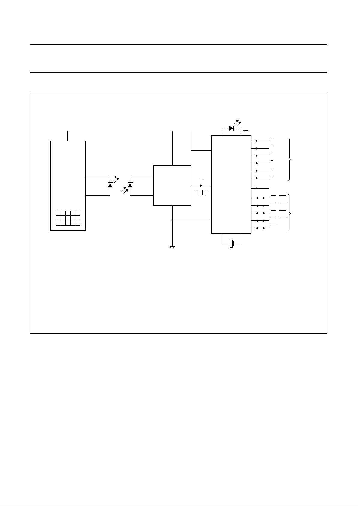
SYSTEM DIAGRAM
handbook, full pagewidth
Remote control transmitters (see individual data sheet for full specification):
SAA3004: V
SAA3007: V
SAA3008: V
SAA3006: V
SAA3010: V
V
Batt
REMOTE
CONTROL
TRANSMITTER
SAA3004
SAA3007
SAA3008
or
SAA3006
SAA3010
= 4to 11 V (max.); 7 × 64 = 448 commands (RECS80 code).
Batt
= 2 to 6.5 V (max.); 20 × 64 = 1280 commands (RECS80 code).
Batt
= 2 to 6.5 V (max.); 20 × 64 = 1280 commands (RECS80 code).
Batt
= 2 to 7 V (max.); 32 × 64 = 2048 commands (RC5 code).
Batt
= 2 to 7 V (max.); 32 × 64 = 2048 commands (RC5 code).
Batt
CQW89A
CQY89A
IR
BPW50
PREAMPLIFIER
+5 V
IR
V
CC
REMOTE
CONTROL
DECODER
IN
SAA3049A
command acknowledge
CA
4 MHz
bits
A
B
C
D
E
F
T0
A0 (S0)
A1 (S1)
A2 (S2)
A3 (S3)
A4
MGE374
data
toggle
address
Fig.1 System diagram.
1996 Sep 13 3
Philips Semiconductors Product specification
Infrared remote control decoder SAA3049A
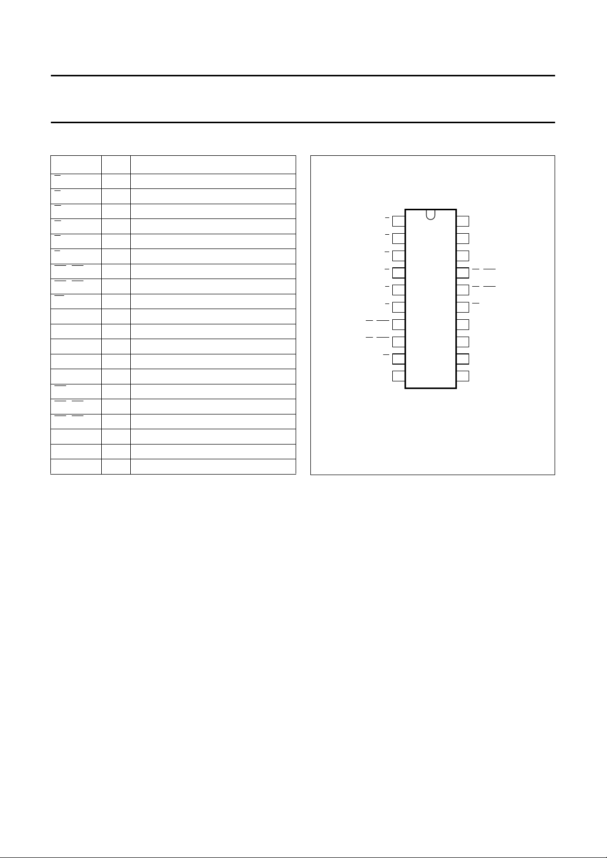
PINNING
SYMBOL PIN DESCRIPTION
A 1 data output
B 2 data output
C 3 data output
D 4 data output
E 5 data output
F 6 data output
A0 (S0) 7 data/address output/input
A1 (S1) 8 data/address output/input
IN 9 digital input
GND 10 ground
MODE 11 RC5/RECS80 mode selection
XTAL1 12 crystal oscillator
XTAL2 13 crystal oscillator
RESET 14 reset input
A4 15 address output/input
A3 (S3) 16 address output/input
A2 (S2) 17 address output/input
T0 18 T0 bit
CRI 19 command received indicator
V
CC
20 supply voltage
handbook, halfpage
1
A
2
B
3
C
4
D
5
E
SAA3049A
6
F
GND
7
8
9
IN
10
MGD347
A0 (S0)
A1 (S1)
Fig.2 Pin configuration.
20
19
18
17
16
15
14
13
12
11
V
CC
CRI
T0
A2 (S2)
A3 (S3)
A4
RESET
XTAL2
XTAL1
MODE
1996 Sep 13 4

Philips Semiconductors Product specification
Infrared remote control decoder SAA3049A
LIMITING VALUES
In accordance with the Absolute Maximum Rating System (IEC 134).
SYMBOL PARAMETER CONDITIONS MIN. MAX. UNIT
V
CC
V
I
I
I
I
O
P
tot
P
o
I
DD
I
SS
T
amb
T
stg
supply voltage −0.5 +7 V
input voltage any pin −0.5 VCC+ 0.5 V
DC input current any pin −−10 mA
DC output current any pin − 10 mA
total power dissipation − 125 mW
power dissipation per output − 30 mW
positive supply current −50 +50 mA
negative supply current −100 +50 mA
operating ambient temperature −40 +85 °C
storage temperature −65 +150 °C
HANDLING
Inputs and outputs are protected against electrostatic charge in normal handling. However, to be totally safe, it is
desirable to take normal precautions appropriate to handling MOS devices (see
“Handling MOS Devices”
).
1996 Sep 13 5
 Loading...