

Philips SAA3008T, SAA3008U-N1 Datasheet

DATA SH EET
Preliminary specification
File under Integrated Circuits, IC02
December 1988
INTEGRATED CIRCUITS
SAA3008
Infrared remote control transmitter
(RECS 80 low voltage)

December 1988 2
Philips Semiconductors Preliminary specification
Infrared remote control transmitter
(RECS 80 low voltage)
SAA3008
GENERAL DESCRIPTION
The SAA3008 transmitter IC is designed for infrared remote control systems. It has a capacity for 1280 commands
arranged in 20 sub-system address groups of 64 commands each. The subsystem address may be selected by
press-button, slider switches or be hard-wired.
Commands are transmitted in patterns which are pulse distance coded. Modulated pulse transmissions allow a
narrow-band receiver to be used for improved noise rejection. The modulation frequency of the SAA3008 is 38 kHz which
is1⁄12 of the oscillator frequency of 455 kHz (typical).
Features
• Modulated transmission
• Ceramic resonator controlled frequency
• Data-word-start with reference time of unique start pattern
• Supply voltage range 2 V to 6.5 V
• 40 mA output current capability
• Very low standby current (< 4 µA at V
DD
= 6 V)
• Up to 20 subsystem address groups; up to 1280 commands
• Up to 64 commands per subsystem address; up to 1280 commands
• Requires few additional components
PACKAGE OUTLINES
SAA3008P: 20-lead DIL; plastic (SOT146); SOT146-1; 1996 December 6.
SAA3008T: 20-lead mini-pack; plastic (SO20; SOT163A); SOT163-1; 1996 December 6.
December 1988 3
Philips Semiconductors Preliminary specification
Infrared remote control transmitter
(RECS 80 low voltage)
SAA3008
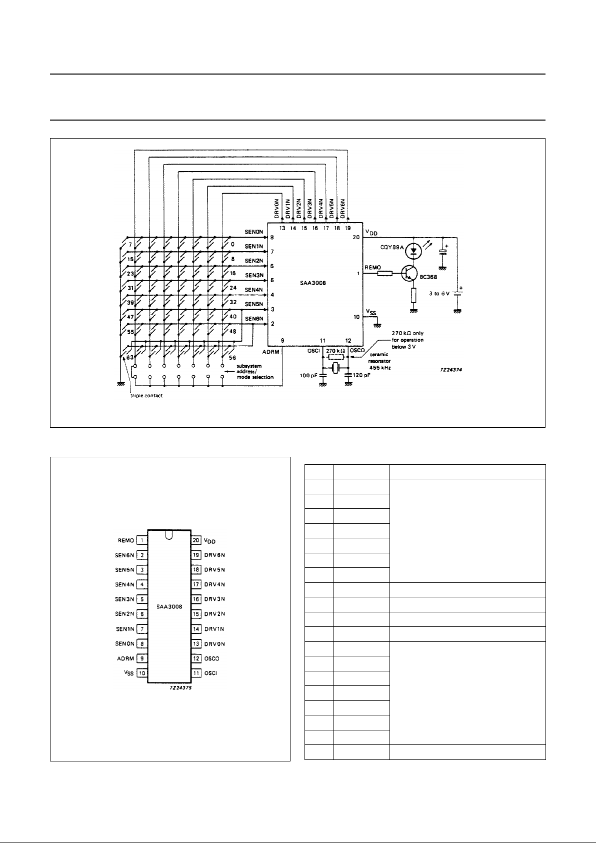
Fig.1 SAA3008 application example.
Fig.2 Pinning diagram.
PINNING
1 REMO remote data output
2 SEN6N
sense inputs from key matrix
3 SEN5N
4 SEN4N
5 SEN3N
6 SEN2N
7 SEN1N
8 SEN0N
9 ADRM address/mode control input
10 V
SS
ground (0 V)
11 OSCI oscillator input
12 OSCO oscillator output
13 DRV0N
drive outputs to key matrix
14 DRV1N
15 DRV2N
16 DRV3N
17 DRV4N
18 DRV5N
19 DRV6N
20 V
DD
positive supply voltage

December 1988 4
Philips Semiconductors Preliminary specification
Infrared remote control transmitter
(RECS 80 low voltage)
SAA3008
FUNCTIONAL DESCRIPTION
Key matrix (DRV0N -DRV6N and SEN0N-SEN6N)
The transmitter keyboard is arranged as a scanned matrix
with seven driver outputs (DRV0N to DRV6N) and seven
sensing inputs (SEN0N to SEN6N) as shown in Fig.1.
The driver outputs are open-drain n-channel transistors
which are conductive in the stand-by mode. The sensing
inputs enable the generation of 56 command codes. With
two external diodes connected (or triple contact), as in
Fig.1, all 64 commands are addressable. The sense lines
have p-channel pull-up transistors, so that they are HIGH
until pulled LOW by connecting them to an output via a key
depression to initiate a code transmission.
The maximum allowable value of contact series resistance
for keyboard switches in the ON-state is 7 kΩ.
Address/mode input (ADRM)
Subsystem addresses are defined by connecting one or
two of the key matrix driver lines (DRV0N to DRV6N) to the
ADRM input. This allows up to 20 subsystem addresses to
be generated for the REMO output (bits S3, S2, S1 and
S0) as shown in Table 1 and Fig.3.
The transmission mode is defined by the DRV6N to ADRM
connection as follows:
• Mode 1 DRV6N not connected to ADRM
• Mode 2 DRV6N connected to ADRM
In Mode 1 the reference time REF equals 3To, this may be
used as a reference time for the decoding sequence.
In Mode 2 an additional modulated pulse has been
inserted into the middle of the reference time, therefore,
these pulses are now separated by 1.5To. This unique
start pattern START uses the detection of a beginning
word (see Fig.3).
When more than one connection is made to ADRM then all
connections should be decoupled using diodes.
The ADRM input has switched pull-up and pull-down
loads. In the stand-by mode only pull-down load is active
and ADRM input is held LOW (this condition is
independent of the ADRM circuit configuration and
minimizes power loss in the standby mode). When a key is
pressed the transmitter becomes active pull-down is
switched OFF, pull-up is switched ON) and the driver line
signals are sensed for the subsystem address coding.
The subsystem address is sensed only within the first scan
cycle, whereas the command code is sensed in every
scan. The transmitted subsystem address remains
unchanged if the subsystem address selection is changed
while the command key is pressed. A chance of the
subsystem address does not start a transmission.
In a multiple keystroke sequence (Fig.6) the second
word B might be transmitted with subsystem address 18 or
19 instead of the preselected subsystem address
(Table 1). This is only relevant for systems decoding
subsystem address 18 or 19.
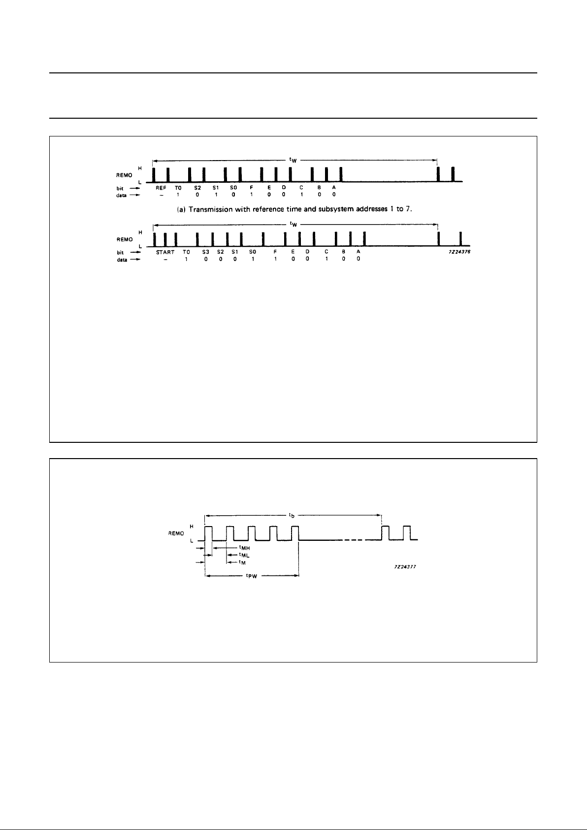
Remote control signal output (REMO)
The REMO output driver stage incorporates a bipolar
emitter-follower which allows a high output current in the
output active (HIGH) state (Fig.7).
The information is defined by the distance ‘t
b
’ between the
leading edges of the modulated pulses (Fig.4). The
distance tbis a multiple of the basic unit To(Table 3) which
equals 1152 periods of the oscillator frequency f
osc
(Table 3). The pulses are modulated with 6 periods of1⁄
12
of the oscillator frequency (38 kHz).
The format of the output data is illustrated in Figs 3 and 4.
A data word starts with the reference time and toggle bit T0
and is followed by the definition bits for the subsystem
address S3, S2, S1 and S0 (bit S3 is transmitted only for
subsystem addresses 8 to 20).
The selected command key is defined by bits F, E, D, C, B
and A as shown in Table 2.
The toggle bit T0 acts as an indication for the decoder
whether the next instruction should be considered as a
new command or not. The codes for the subsystem
address and the selected key are given in Table 3.
December 1988 5
Philips Semiconductors Preliminary specification
Infrared remote control transmitter
(RECS 80 low voltage)
SAA3008
Oscillator (OSCI, OSCO)
The external components for the oscillator circuit are connected to OSCI and OSCO. The oscillator operates with a
ceramic resonator in the frequency range 350 kHz to 500 kHz, as defined by the resonator. When operating at a supply
voltage of below 3 V a 270 kHz resistor should be connected in parallel with the resonator.
Fig.3 Data format of remote control signal (REMO).
Where:
Reference time
start pattern T0 toggle bit
S3, S2, S1, S0 subsystem address
A to F command bits
t
W word length
binary values determined by pulse spacing
(b) Transmission with start-pattern and subsystem address 8 to 20.
Fig.4 Waveform for one pulse period at REMO output; for timing values see Table 3.

December 1988 6
Philips Semiconductors Preliminary specification
Infrared remote control transmitter
(RECS 80 low voltage)
SAA3008
Table 1 Definition of subsystem addresses
address driver line(s) subsystem address
number connected to ADRM S3 S2 S1 S0
1 no connection − 11 1
2 DRV0N − 00 0
3 DRV1N − 00 1
4 DRV2N − 01 0
5 DRV3N − 01 1
6 DRV4N − 10 0
7 DRV5N − 10 1
8 DRV0N and DRV2N 0 0 0 0
9 DRV0N and DRV3N 1 0 0 0
10 DRV0N and DRV4N 0 1 0 0
11 DRV0N and DRV5N 1 1 0 0
12 DRV1N and DRV2N 0 0 0 1
13 DRV1N and DRV3N 1 0 0 1
14 DRV1N and DRV4N 0 1 0 1
15 DRV1N and DRV5N 1 1 0 1
16 DRV2N and DRV3N 1 0 1 0
17 DRV2N and DRV4N 0 1 1 0
18 DRV2N and DRV5N 1 1 1 0
19 DRV3N and DRV4N 0 1 1 1
20 DRV3N and DRV5N 1 1 1 1
 Loading...