

Philips SA615DK, SA615N, SA615D Datasheet

INTEGRATED CIRCUITS
SA615
High performance low power mixer FM IF
system
Product specification
Replaces data of 1992 Nov 03
IC17 Data Handbook
1997 Nov 07
Philips Semiconductors Product specification
SA615High performance low power mixer FM IF system
DESCRIPTION
The SA615 is a high performance monolithic low-power FM IF
system incorporating a mixer/oscillator, two limiting intermediate
frequency amplifiers, quadrature detector, muting, logarithmic
received signal strength indicator (RSSI), and voltage regulator. The
SA615 combines the functions of Signetics’ SA602 and SA604A, but
features a higher mixer input intercept point, higher IF bandwidth
(25MHz) and temperature compensated RSSI and limiters
permitting higher performance application. The SA615 is available in
20-lead dual-in-line plastic, 20-lead SOL (surface-mounted miniature
package) and 20-lead SSOP (shrink small outline package).
The SA605 and SA615 are functionally the same device types. The
difference between the two devices lies in the guaranteed
specifications. The SA615 has a higher I
intercept point, lower conversion mixer gain, lower limiter gain, lower
AM rejection, lower SINAD, higher THD, and higher RSSI error than
the SA615. Both the SA605 and SA615 devices will meet the EIA
specifications for AMPS and TACS cellular radio applications.
For additional technical information please refer to application notes
AN1994, 1995 and 1996, which include example application
diagrams, a complete overview of the product, and artwork for
reference.
, lower input third order
CC
FEATURES
•Low power consumption: 5.7mA typical at 6V
•Mixer input to >500MHz
•Mixer conversion power gain of 13dB at 45MHz
•Mixer noise figure of 4.6dB at 45MHz
•XTAL oscillator effective to 150MHz (L.C. oscillator to 1GHz local
oscillator can be injected)
•102dB of IF Amp/Limiter gain
•25MHz limiter small signal bandwidth
•Temperature compensated logarithmic Received Signal Strength
Indicator (RSSI) with a dynamic range in excess of 90dB
•Two audio outputs – muted and unmuted
•Low external component count; suitable for crystal/ceramic/LC
filters
•Excellent sensitivity: 0.22µV into 50Ω matching network for 12dB
SINAD (Signal to Noise and Distortion ratio) for 1kHz tone with RF
at 45MHz and IF at 455kHz
•SA615 meets cellular radio specifications
•ESD hardened
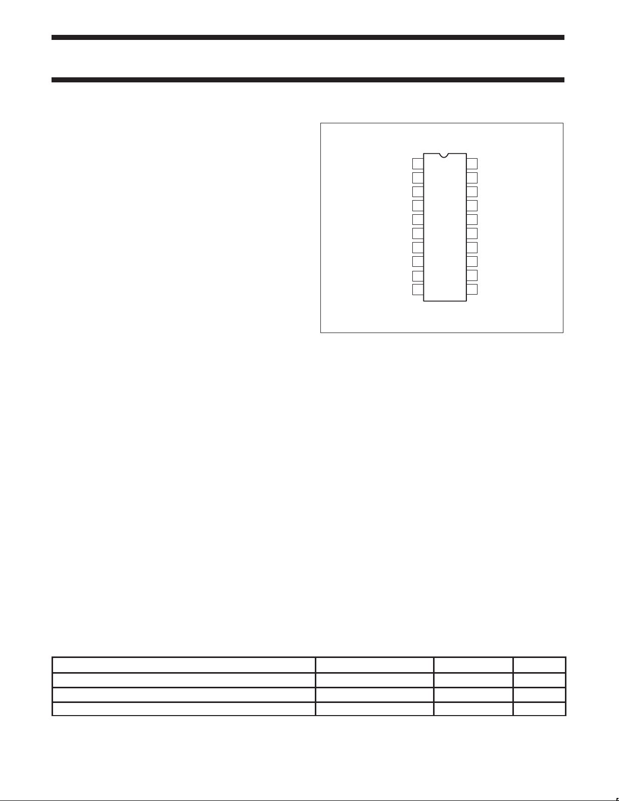
PIN CONFIGURATION
N, D and DK Packages
RF
1
IN
RF BYPASS
XTAL OSC
XTAL OSC
MUTE
RSSI
MUTED AUDIO OUT
UNMUTED AUDIO OUT
QUADRATURE IN
NOTE:
See back page for package dimensions
2
3
4
5
IN
6
V
CC
7
OUT
8
9
10
Figure 1. Pin Configuration
20
19
18
17
16
15
14
13
12
11
APPLICATIONS
•Cellular radio FM IF
•High performance communications receivers
•Single conversion VHF/UHF receivers
•SCA receivers
•RF level meter
•Spectrum analyzer
•Instrumentation
•FSK and ASK data receivers
•Log amps
•Wideband low current amplification
MIXER OUT
IF AMP DECOUPLING
IF AMP IN
IF AMP DECOUPLING
IF AMP OUT
GND
LIMITER IN
LIMITER DECOUPLING
LIMITER DECOUPLING
LIMITER OUT
SR00341
ORDERING INFORMATION
DESCRIPTION TEMPERATURE RANGE ORDER CODE DWG #
20-Pin Plastic Dual In-Line Package (DIP) –40 to +85°C SA615N SOT146-1
20-Pin Plastic Small Outline Large (SOL) package –40 to +85°C SA615D SOT108-1
20-Pin Plastic Shrink Small Outline Package (SSOP) –40 to +85°C SA615DK SOT266-1
1997 Nov 07 853-1402 18665
2
Philips Semiconductors Product specification
SA615High performance low power mixer FM IF system
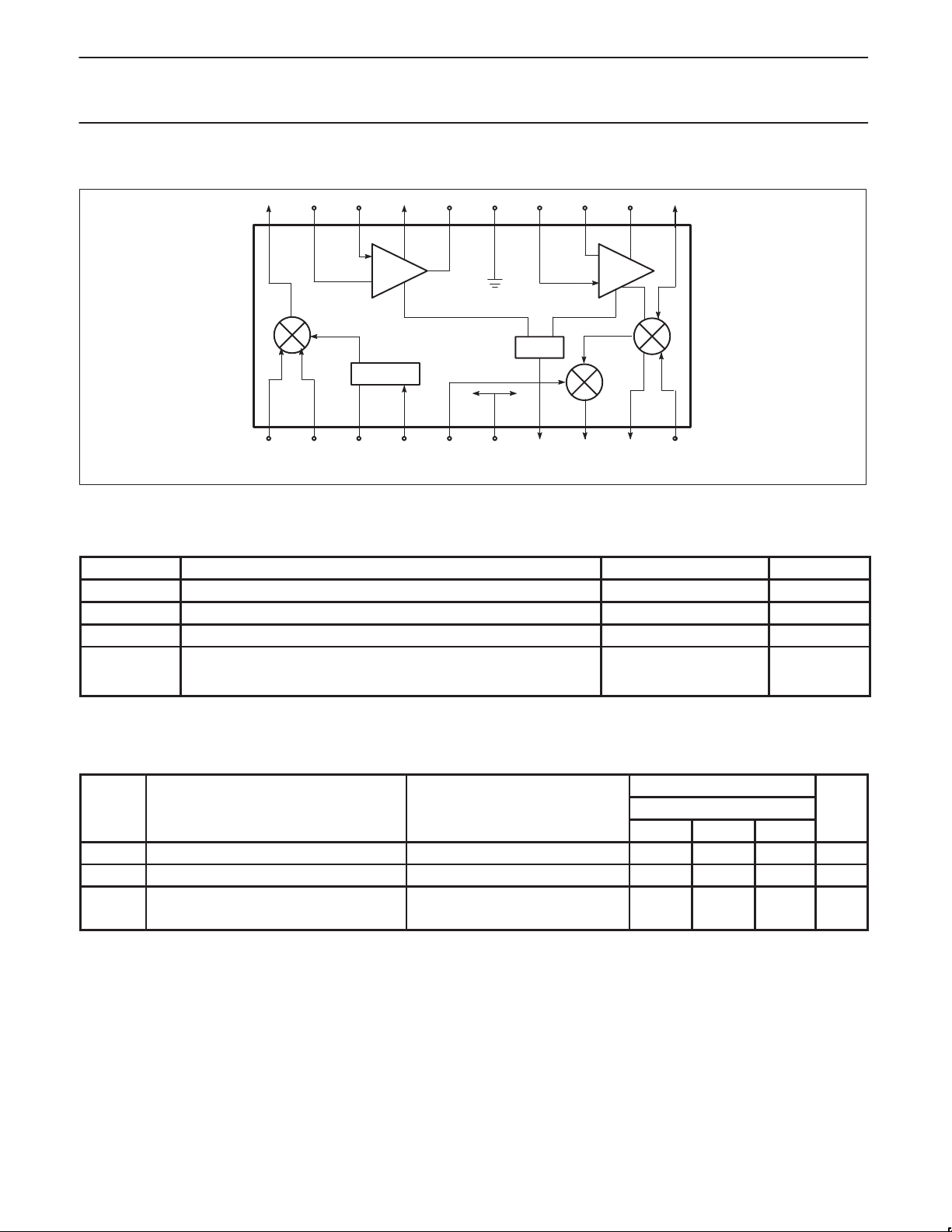
BLOCK DIAGRAM
20 19 18 17 16 15 14 13 12 11
IF
AMP
OSCILLATOR
EB
RSSI
LIMITER
10987654321
SR00342
Figure 2. Block Diagram
ABSOLUTE MAXIMUM RATINGS
SYMBOL PARAMETER RATING UNITS
T
V
θ
CC
STG
T
A
JA
Single supply voltage 9 V
Storage temperature range –65 to +150 °C
Operating ambient temperature range SA615 –40 to +85 °C
Thermal impedance D package
N package
SSOP package
90
75
117
°C/W
DC ELECTRICAL CHARACTERISTICS
VCC = +6V, TA = 25°C; unless otherwise stated.
LIMITS
SYMBOL PARAMETER TEST CONDITIONS SA615 UNITS
MIN TYP MAX
V
I
Power supply voltage range 4.5 8.0 V
CC
DC current drain 5.7 7.4 mA
CC
Mute switch input threshold (ON) 1.7 V
(OFF) 1.0 V
1997 Nov 07
3
Philips Semiconductors Product specification
SA615High performance low power mixer FM IF system
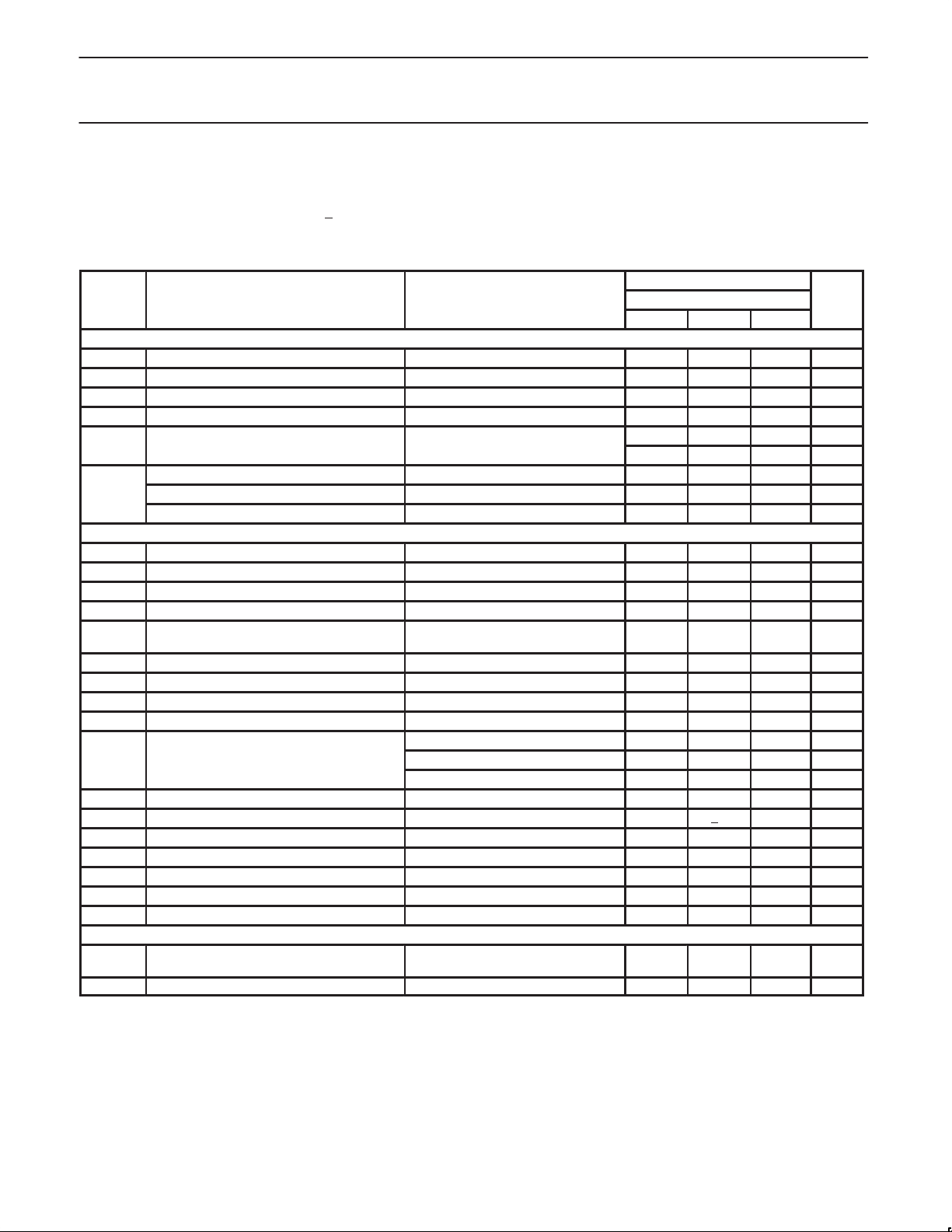
AC ELECTRICAL CHARACTERISTICS
TA = 25°C; VCC = +6V, unless otherwise stated. RF frequency = 45MHz + 14.5dBV RF input step–up; IF frequency = 455kHz; R17 = 5.1k; RF
level = –45dBm; FM modulation = 1kHz with +
Test circuit Figure 3. The parameters listed below are tested using automatic test equipment to assure consistent electrical characterristics.
The limits do not represent the ultimate performance limits of the device. Use of an optimized RF layout will improve many of the listed
parameters.
SYMBOL PARAMETER TEST CONDITIONS SA615 UNITS
Mixer/Osc section (ext LO = 300mV)
f
Input signal frequency 500 MHz
IN
f
OSC
Crystal oscillator frequency 150 MHz
Noise figure at 45MHz 5.0 dB
Third-order input intercept point f1 = 45.00; f2 = 45.06MHz -12 dBm
Conversion power gain Matched 14.5dBV step-up 8.0 13 dB
RF input resistance Single-ended input 3.0 4.7 kΩ
RF input capacitance 3.5 4.0 pF
Mixer output resistance (Pin 20) 1.25 1.50 kΩ
IF section
IF amp gain 50Ω source 39.7 dB
Limiter gain 50Ω source 62.5 dB
Input limiting -3dB, R17 = 5.1k T est at Pin 18 -109 dBm
AM rejection 80% AM 1kHz 25 33 43 dB
Audio level, R10 = 100k 15nF de-emphasis 60 150 260
Unmuted audio level, R11 = 100k 150pF de-emphasis 530 mV
SINAD sensitivity RF level -118dB 12 dB
THD Total harmonic distortion -30 -42 dB
S/N Signal-to-noise ratio No modulation for noise 68 dB
IF RSSI output, R9 = 100kΩ
RSSI range R9 = 100kΩ Pin 16 80 dB
RSSI accuracy R9 = 100kΩ Pin 16 +2 dB
IF input impedance 1.40 1.6 kΩ
IF output impedance 0.85 1.0 kΩ
Limiter intput impedance 1.40 1.6 kΩ
Unmuted audio output resistance 58 kΩ
Muted audio output resistance 58 kΩ
RF/IF section (int LO)
Unmuted audio level 4.5V = VCC, RF level = -27dBm 450
System RSSI output 4.5V = VCC, RF level = -27dBm 4.3 V
NOTE:
1. The generator source impedance is 50Ω, but the SA615 input impedance at Pin 18 is 1500Ω. As a result, IF level refers to the actual signal
that enters the SA615 input (Pin 8) which is about 21dB less than the ”available power” at the generator.
8kHz peak deviation. Audio output with C-message weighted filter and de-emphasis capacitor.
LIMITS
MIN TYP MAX
50Ω source -1.7 dB
1
IF level = -118dBm 0 160 800 mV
IF level = -68dBm 1.7 2.5 3.3 V
IF level = -18dBm 3.6 4.8 5.8 V
mV
mV
RM
S
RM
S
1997 Nov 07
4

Philips Semiconductors Product specification
SA615High performance low power mixer FM IF system
CIRCUIT DESCRIPTION
The SA615 is an IF signal processing system suitable for second IF
or single conversion systems with input frequency as high as 1GHz.
The bandwidth of the IF amplifier is about 40MHz, with 39.7dB(v) of
gain from a 50Ω source. The bandwidth of the limiter is about
28MHz with about 62.5dB(v) of gain from a 50Ω source. However,
the gain/bandwidth distribution is optimized for 455kHz, 1.5kΩ
source applications. The overall system is well-suited to battery
operation as well as high performance and high quality products of
all types.
The input stage is a Gilbert cell mixer with oscillator. Typical mixer
characteristics include a noise figure of 5dB, conversion gain of
13dB, and input third-order intercept of –10dBm. The oscillator will
operate in excess of 1GHz in L/C tank configurations. Hartley or
Colpitts circuits can be used up to 100MHz for xtal configurations.
Butler oscillators are recommended for xtal configurations up to
150MHz.
The output of the mixer is internally loaded with a 1.5kΩ resistor
permitting direct connection to a 455kHz ceramic filter. The input
resistance of the limiting IF amplifiers is also 1.5kΩ. With most
455kHz ceramic filters and many crystal filters, no impedance
matching network is necessary. To achieve optimum linearity of the
log signal strength indicator , there must be a 12dB(v) insertion loss
between the first and second IF stages. If the IF filter or interstage
network does not cause 12dB(v) insertion loss, a fixed or variable
resistor can be added between the first IF output (Pin 16) and the
interstage network.
The signal from the second limiting amplifier goes to a Gilbert cell
quadrature detector . One port of the Gilbert cell is internally driven
by the IF. The other output of the IF is AC-coupled to a tuned
quadrature network. This signal, which now has a 90
relationship to the internal signal, drives the other port of the
multiplier cell.
Overall, the IF section has a gain of 90dB. For operation at
intermediate frequencies greater than 455kHz, special care must be
given to layout, termination, and interstage loss to avoid instability.
The demodulated output of the quadrature detector is available at
two pins, one continuous and one with a mute switch. Signal
attenuation with the mute activated is greater than 60dB. The mute
input is very high impedance and is compatible with CMOS or TTL
levels.
A log signal strength completes the circuitry. The output range is
greater than 90dB and is temperature compensated. This log signal
strength indicator exceeds the criteria for AMPs or TACs cellular
telephone.
NOTE: dB(v) = 20log V
OUT/VIN
° phase
1997 Nov 07
5
 Loading...