

Philips SA577D Datasheet

RF COMMUNICATIONS PRODUCTS
SA577
Unity gain level programmable power
compandor
Product specification
Replaces data of December 15, 1993
IC17 Data Handbook
Philips Semiconductors
1997 Nov 07
Philips Semiconductors Product specification
SYMBOL
PARAMETER
UNITS
SA577Unity gain level programmable low power compandor
DESCRIPTION
The SA577 is a unity gain level programmable compandor designed
for low power applications. The SA577 is internally configured as an
expandor and a compressor to minimize external component count.
FEA TURES
•Operating voltage range: 1.8V to 7V
•Low power consumption (1.4mA @ 3.6V)
•0dB level programmable (10mV
RMS
to 1.0V
RMS
)
•Over 90dB of dynamic range
•Wide input/output swing capability (rail-to-rail)
•Low external component count
•SA577 meets cellular radio specifications
•ESD hardened
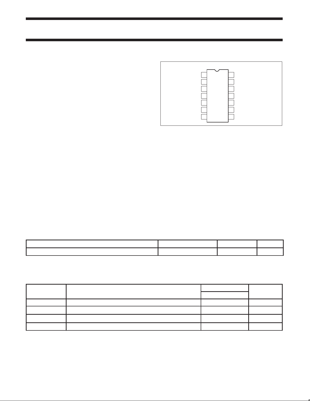
PIN CONFIGURATION
D Package
GCELL
RECT
EXP
EXP
1
IN
2
IN
3
CAP
4
OUT
5
V
REF
6
I
REF
7
GND
Figure 1. Pin Configuration
14
V
CC
13
COMP
12
COMP
11
COMP
10
RECT
9
GCELL
8
COMP
APPLICATIONS
•High performance portable communications
•Cellular radio
•Cordless telephone
•Consumer audio
•Wireless microphones
•Modems
•Electric organs
•Hearing aids
•Automatic level control (ALC)
CAP2
IN
CAP1
IN
IN
OUT
SR00716
ORDERING INFORMATION
DESCRIPTION TEMPERATURE RANGE ORDER CODE DWG #
14-Pin Plastic Small Outline (SO)
ABSOLUTE MAXIMUM RATINGS
T
V
θ
CC
T
A
STG
JA
Supply voltage 8 V
Operating ambient temperature range –40 to +85
Storage temperature range –65 to +150
Thermal impedance SO 125
–40 to +85°C
SA577D SOT108-1
RATING
SA577
°C
°C
°C/W
1997 Nov 07 853-1535 18666
2
Philips Semiconductors Product specification
dBV
V
V
SA577Unity gain level programmable low power compandor
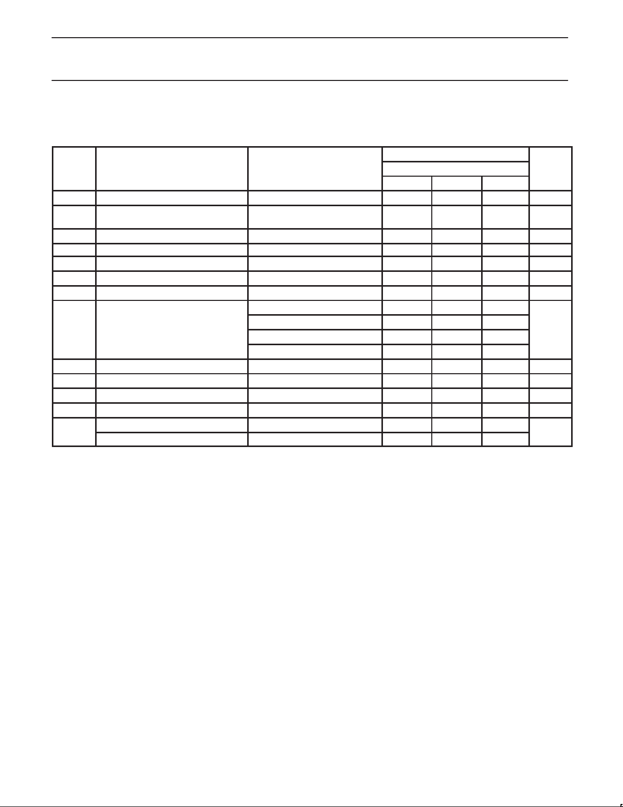
ELECTRICAL CHARACTERISTICS
TA = 25°C, VCC = 3.6VDC, compandor 0dB level = –20dBV = 100mV
R1, R2 and R3 are 1% resistors.
SYMBOL PARAMETER TEST CONDITIONS SA577 UNITS
V
I
V
Supply voltage
CC
Supply current
CC
Reference voltage
REF
R
Summing amp output load 10 kΩ
L
1
2
THD Total harmonic distortion 1kHz, 0dB, BW = 3.5kHz 0.25 1.5 %
E
Expandor output noise voltage BW = 20kHz, RS = 0Ω 10 25 µV
NO
0dB Unity gain level 0dB at 1kHz –1.5 0.18 1.5 dB
Programmable range
3
R1 = R3 = 18.7kΩ, R2 = 24.3kΩ 0
R1 = R3 = 22.6kΩ, R2 = 100kΩ –10
R1 = R3 = 7.15kΩ, R2 = 100kΩ –20
R1 = R3 = 1.33kΩ, R2 = 200kΩ –40
V
Output voltage offset No signal –150 1 150 mV
OS
Expandor output DC shift No signal to 0dB –100 7 100 mV
Tracking error relative to 0dB output -20dB expandor –1.0 0.3 1.0 dB
Crosstalk, COMP to EXP 1kHz, 0dB, C
Output swing low 0.2
O
Output swing high VCC – 0.2
, output load RL = 10kΩ, Freq = 1kHz, unless otherwise specified.
RMS
LIMITS
MIN TYP MAX
2 3.6 7 V
No signal
= 100kΩ
R
2
1.4 2 mA
VCC = 3.6V 1.7 1.8 1.9 V
= 10µF –80 –65 dB
REF
NOTE:
1. Operation down to V
2. Reference voltage, V
3. Unity gain level can be adjusted CONTINUOUSLY between –40dBV = 10mV
= 1.8V is possible, see application note AN1762.
CC
, is typically at 1/2 VCC.
REF
AN1762.
and 0dBV = 1.0V
RMS
. For details see application note
RMS
1997 Nov 07
3
 Loading...