

Philips S1A, S1D, S1J, S1G, S1M Datasheet
DISCRETE SEMICONDUCTORS
DATA SH EET
ook, halfpage
M3D168
S1 series
SMA controlled avalanche rectifiers
Product specification 2000 Feb 14

Philips Semiconductors Product specification
SMA controlled avalanche rectifiers S1 series
FEATURES
• Glass passivated
• High maximum operating temperature
• Ideal for surface mount automotive applications
• Low leakage current
DESCRIPTION
DO-214AC surface mountable package with glass
passivated chip.
The well-defined void-free case is of a transfer-moulded
thermo-setting plastic.The small rectangular package has
two J bent leads.
• Excellent stability
• Guaranteed avalanche energy absorption capability
• UL 94V-O classified plastic package
• Shipped in 12 mm embossed tape
• Marking: cathode, date code, type code
lumns
ka
cathode
band
• Easy pick and place.
Top view Side view
MSA474
Fig.1 Simplified outline (DO-214AC) and symbol.
LIMITING VALUES
In accordance with the Absolute Maximum Rating System (IEC 134).
SYMBOL PARAMETER CONDITIONS MIN. MAX. UNIT
V
RRM
repetitive peak reverse voltage
S1A − 50 V
S1B − 100 V
S1D − 200 V
S1G − 400 V
S1J − 600 V
S1K − 800 V
S1M − 1000 V
V
R
continuous reverse voltage
S1A − 50 V
S1B − 100 V
S1D − 200 V
S1G − 400 V
S1J − 600 V
S1K − 800 V
S1M − 1000 V
2000 Feb 14 2

Philips Semiconductors Product specification
SMA controlled avalanche rectifiers S1 series
SYMBOL PARAMETER CONDITIONS MIN. MAX. UNIT
V
RMS
I
F(AV)
I
FSM
T
stg
T
j
root mean square voltage
S1A − 35 V
S1B − 70 V
S1D − 140 V
S1G − 280 V
S1J − 420 V
S1K − 560 V
S1M − 700 V
average forward current averaged over any 20 ms period;
− 1A
Ttp= 110 °C; see Fig.2
non-repetitive peak forward current t = 8.3 ms half sine wave;
S1A to S1J − 30 A
S1K and S1M − 25 A
Tj=25°C prior to surge;
VR=V
RRMmax
storage temperature −65 +175 °C
junction temperature See Fig.3 −65 +175 °C
ELECTRICAL CHARACTERISTICS
Tj=25°C unless otherwise specified.
SYMBOL PARAMETER CONDITIONS TYP. MAX. UNIT
V
F
I
R
forward voltage IF= 1 A; see Fig.4 − 1.1 V
reverse current VR=V
RRMmax
; see Fig.5
S1A to S1J − 1 µA
S1K and S1M − 5 µA
V
R=VRRMmax
t
rr
reverse recovery time when switched from IF= 0.5 A to IR=1A;
; Tj= 165 °C; see Fig.5 − 50 µA
1 −µs
measured at IR= 0.25 A; see Fig.9
C
d
diode capacitance VR= 4 V; f = 1 MHz; see Fig.6 8 − pF
THERMAL CHARACTERISTICS
SYMBOL PARAMETER CONDITIONS VALUE UNIT
R
R
th j-tp
th j-a
thermal resistance from junction to tie-point; see Fig.7 27 K/W
thermal resistance from junction to ambient note 1 100 K/W
note 2 150 K/W
Notes
1. Device mounted on Al
printed-circuit board, 0.7 mm thick; thickness of copper ≥35 µm.
2O3
2. Device mounted on epoxy-glass printed-circuit board, 1.5 mm thick; thickness of copper ≥40 µm. For more
information please refer to the
‘General Part of associated Handbook’
.
2000 Feb 14 3
Philips Semiconductors Product specification
SMA controlled avalanche rectifiers S1 series
GRAPHICAL DATA
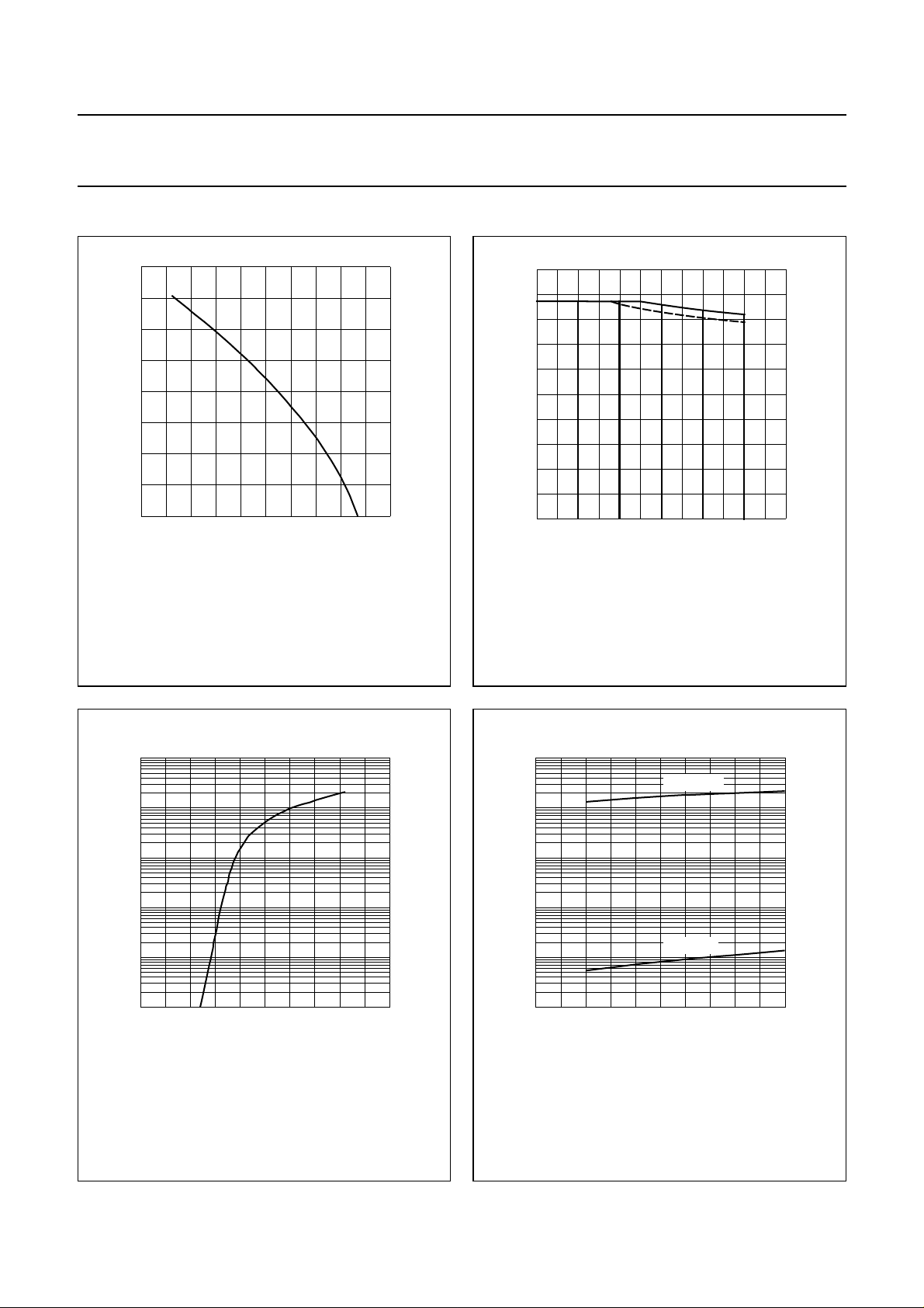
handbook, halfpage
2
I
F(AV)
(A)
1.5
1
0.5
0
0 40 200
VR=V
; δ = 0.5; a = 1.57.
RRMmax
80
120 160
Ttp (°C)
Fig.2 Maximum permissible average forward
current as a function of tie-point
temperature (including losses due to
reverse leakage).
MCD822
200
handbook, halfpage
T
j
(°C)
160
120
80
DG JKM
40
0
0 400 1200
Device mounted as shown in Fig.8.
Solid line: Al2O3 printed-circuit board.
Dotted line: epoxy printed-circuit board.
800
MGD483
VR (V)
Fig.3 Maximum permissible junction temperature
as a function of reverse voltage.
2
10
handbook, halfpage
I
F
(A)
10
1
−1
10
−2
10
−3
10
Tj=25°C.
1.5 2
MCD795
VF (V)
Fig.4 Forward current as a function of forward
voltage; typical values.
VR (%V
MCD802
Rmax
1000 20 40
)
2
10
handbook, halfpage
I
R
(µA)
10
1
−1
10
−2
10
−3
2.50 0.5 1
10
Tj = 165 °C
Tj = 25 °C
60 80
Fig.5 Reverse current as a function of reverse
voltage; typical values.
2000 Feb 14 4
 Loading...