

Philips RSAT 2 Customer's Manual
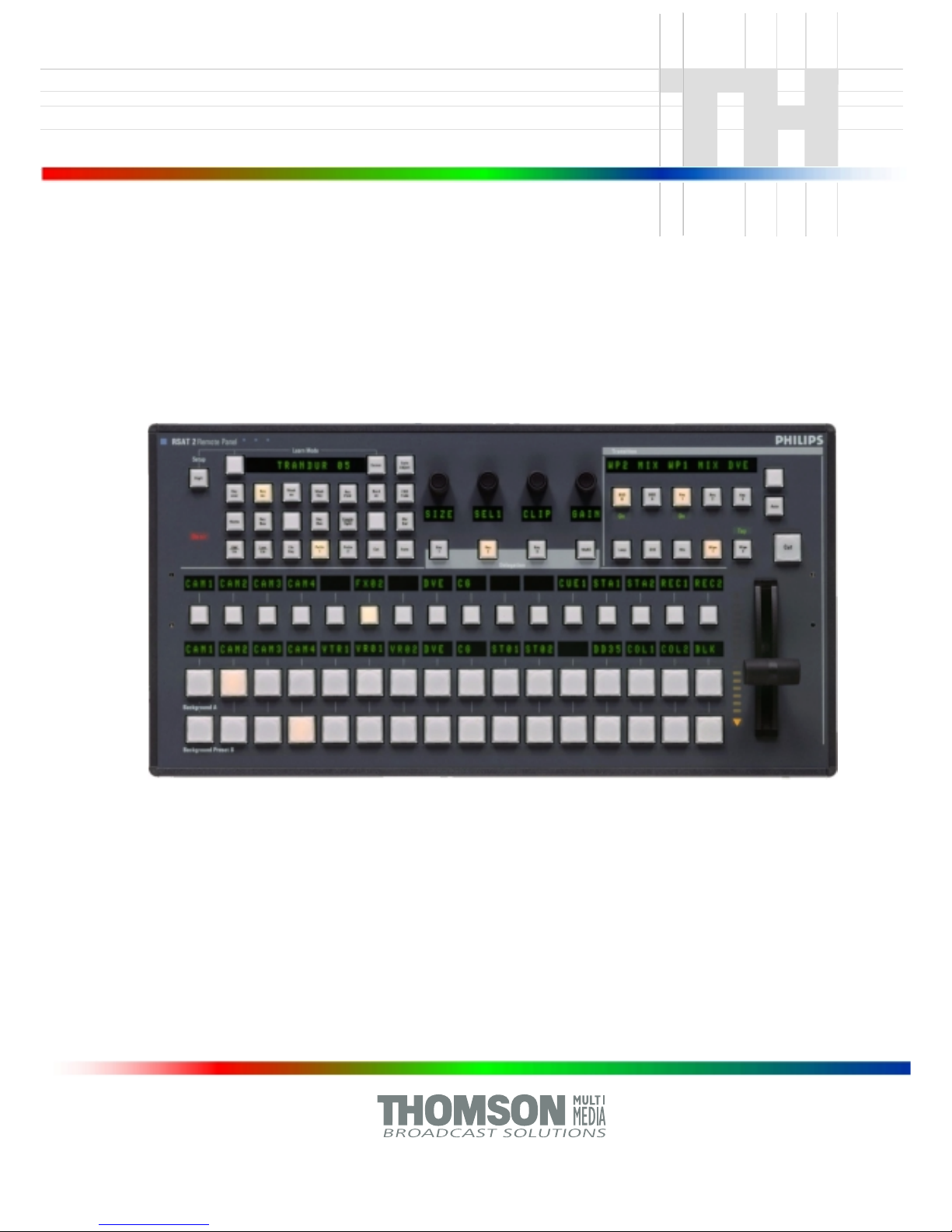
RSAT 2
Remote Control Panel
Customer‘s Manual
BTS Media Solutions GmbH
Brunnenweg 9
D-64331 Weiterstadt, Germany
P.O. Box 1 165
Tel: +49 (0) 6155-870-0
Fax: +49 (0) 6155-870-300
Web Sites
Internet: www.thomsonbroadcast.com
www.imagingsystems.de
Intranet: www.weiterstadt.thmulti.com
Information in this document is subject to change without notice.
This document and any updates and/or supplemental information, including any copies thereof, cannot be reproduced, neither
communicated to a third party, without written authorization from THOMSON multimedia Broadcast Solutions.
Please notify THOMSON multimedia Broadcast Solutions of any errors in this document. We also would appreciate any comments
you have to improve this manual.
BTS Media Solutions GmbH 2002. All rights reserved.
Copyrights
Published by
All product names mentioned in this manual are the trademarks of their respective owners.
Trademarks
Before reading the entire
manual, please check for any
supplements at the end
of the manual.
Item Rev Date SerialNoPages
affected
Volume/Contents Remarks
1 0 07.2000 100 All Customer‘s Manual First Issue
2 1 11.2001 chapter 6 Oberating Instructions Macros
Remote Panel RSAT 2
Revision Report
Documentation Order Number
Customer’s Manual
RU 0065, 000 351 763 000

Remote Panel RSA T2
Contents
I
Operating Instructions - Rev . 1 / 11.2001
CONTENTS
Page
Revision Report
1. General 1
1.1 Application examples 1
1.2 Control and display elements 1
2. Technical Data 3
3. Installation and Start-up 5
3.1 Safety Instructions 5
3.2 Mounting the Remote Control Panel RSA T2 6
3.3 Rack Mounting 8
3.4 Connecting to the DD35 control panel 10
3.5 Port re-configuration RS-422 / RS-232 11
4. Operation 13
4.1 How to start the Satellite Panel 13
4.2 How to learn a new function 14
4.3 What can be learned 15
4.4 Loading and saving setups 16
4.5 RSAT2 Makros and Control Panel M/E Delegation 19
5. Setup / Tests 22
6. Annex 24
6.2 Default Macros 25

Remote Panel RSA T2
Contents
II
Operating Instructions - Rev . 1 / 11.2001
Remote Control Panel RSA T2 1. General
Operating Instructions - Rev . 1 / 11.2001
1
1. GENERAL
The remote control panel RSAT2 is used for copying button functions of the DD35
main operation panels for control of mixer functions from another workplace.
Connected to DD35 main panel via RS-422 cable which can be ordered optionally.
When the learn mode is applied single button functions also the built in Digipots and
the Fader can be trained with functions of the DD35 main panel –
Standard predefined settings for single M/E operation are also availlable.
1.1 APPLICATION EXAMPLES
Remote control on source selection, effects register recall, transitions, macros,
Shot-Box, Keyer adjust ...., specifically in conjunction with the use of an additional
sidepanel control PC.
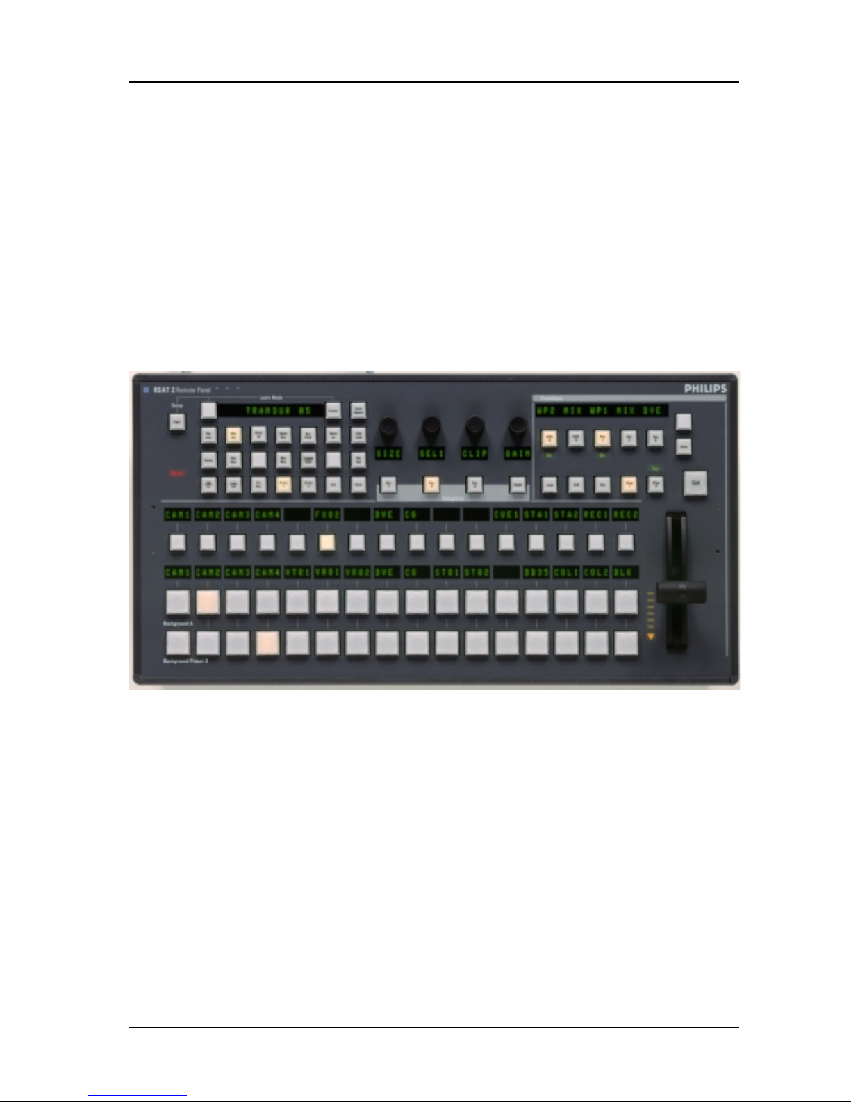
Fig. 1: RSAT2 Remote Control Panel
1.2 CONTROL AND DISPLAY ELEMENTS
3 x16 button source selection busses with 4 digit displays
Transition control field with fader
4x Digipots
4x Delegation buttons
Learn mode buttons with Display
2x Menu control buttons (Step up/down)
22 additionally programmable buttons
In learn mode only one function per button or digipot is programmable. Delegation
functions are not available. Also, functions of the display panel RPV are not recordable.

Remote Control Panel RSAT11. General
2
Operating Instructions - Rev . 1 / 11.2001
The programmable memory of the RSAT2 is part of the DD35. Thus the programmed function set for the RSA T2 buttons can be switched from application to application. More complex button sequences can be achieved by programmed recall of
macro buttons of the DD35 main panel.
The standard unit is equipped with 1x reconfigurable 9 Pin D-Sub interface for connection to a host processor. Without further options the factory configuration is a
RS-422/485 port for direct connection to DD35’s panel controller.

Remote Control Panel RSA T2 2. Technical Data
Operating Instructions - Rev . 1 / 11.2001
3
2. TECHNICAL DATA
Mechanics Width: 240 mm, Length: 464 mm, Depth: 115 mm
Weight: 5 kg
Desk cut out: 441 x 217 mm
Optional 19” Mounting frame
Voltage supply Line voltage: 100 V – 240 V $10 %, autosense
Line current: 0.8 A
Line frequency: 50 Hz to 60 Hz
Wide AC range power supply block
Power consumption: < 50 W
Environmental Operating temperature: +0° C ... 40° C
requirements Storage/transport temp: –40° C ... 85° C
Humidity: v95%, DIN IEC 68-2-14
non-condensing
Electromagnetic EMA: EN 55103-1, EN 55 022, Class B,
compability ESD: EN 61000-4-2
EMI: EN 61000-4-3
Burst: EN 61000-4-4 , IEC 1000-4-4
RF immunity: EN 61000-4-6
Safety VDE 0805, EN 60 950
Interface RS-422/485 port for direct connection to the DD35 panel controller.
9pin D-sub, female. Port re-configurable for RS-232.
Communication is asynchron with 38.4 kbaud, 1 start, 8 data, no parity, 1 stop bit.A factory re-configuration is recommended for use of an RSA T2 with a PC.
Standard Accessories Accessory pack with tools fuses and button spare parts.
Options 19” Mounting frame für rack mounting.
Order no.: RC 2326, 000 351 762 600

Remote Control Panel RSA T22. Technical Data
4
Operating Instructions - Rev . 1 / 11.2001
Remote Control Panel RSA T2 3. Installation and Startup
Operating Instructions - Rev . 1 / 11.2001
5
3. INSTALLATION AND STARTUP
3.1 SAFETY INSTRUCTIONS
Caution!
These instructions are for use by qualified personnel only. T o reduce the risk
of electric shock, do not perform any installation other than that contained in
the Operating Instructions unless you are qualified to do so.
Refer all servicing to qualified service personnel.
Attention!
Electrostatic sensitive devices on the p. c. boards. Observe the following
precaution for handling:
Handling or mounting the RSAT2 unit call for special attention to personal
safety. Personnel should be connected to ground potential via a wristlet (e.g.
3M Wristlet Serial 2200).
Do not touch the p. c. boards during mounting.
Repair the p. c. boards only at static-safe work stations.
Use antistatical protective bags when carrying the p.c. boards.
Remote Control Panel RSA T23. Installation and Startup
6
Operating Instructions - Rev . 1 / 11.2001
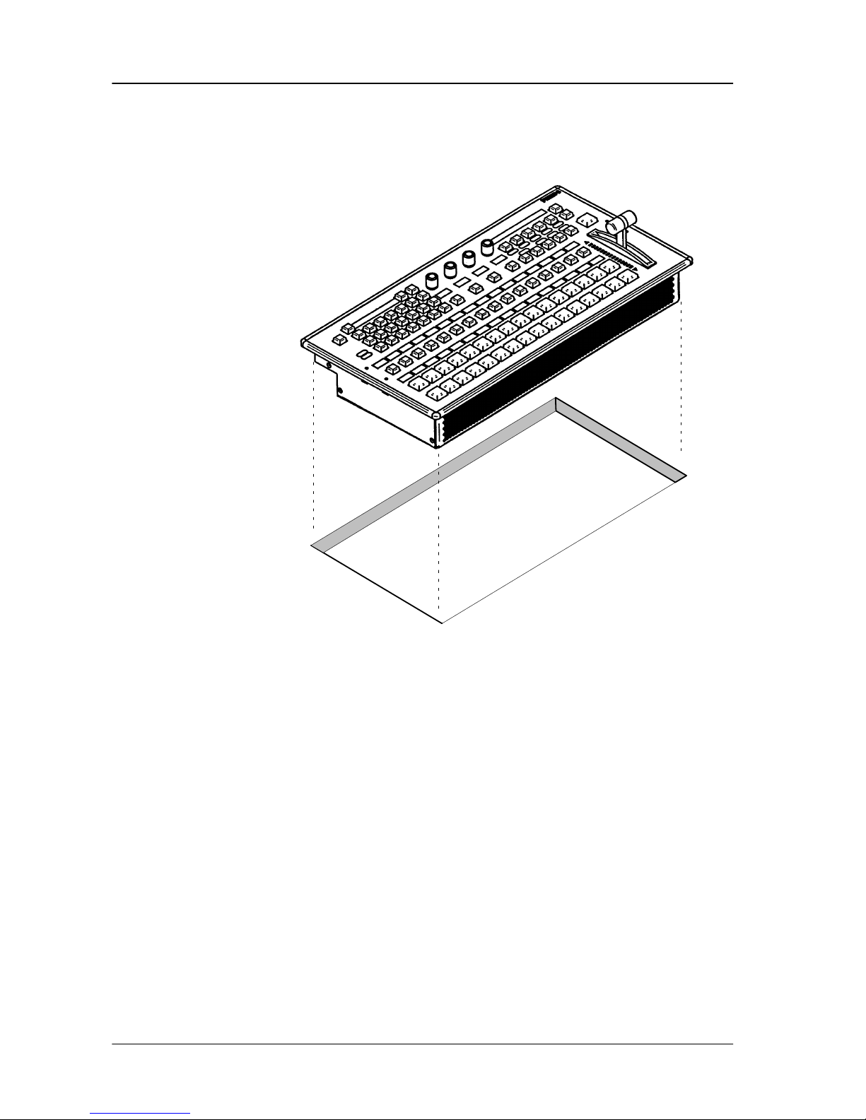
3.2 DESK MOUNTING
Cut-out dimensions: 441 x 217 mm
Fig. 2: Panel cut out
Unpack the R S AT2 panel and remove the panel module from the mounting box.
The locking mechanism can be removed by the two release tools delivered in
the accessory pack. Therefore the module can be removed very simply.
Disconnect the cables.
Cut-out the openings in the desk.
Put in the mounting box of the panel. For fastening, bores are provided in the
frame. The housing can be fastened with countersunk wood screws with a diameter of 4 mm. The length of the screw depends on the plate thickness of the
desk. A set with mounting parts is included in the delivery of the panel.
Connect the cables into the corresponding plugs of the modules.
Put in the panel module in in the mounting box. By pressing, the modules enga-
ges independently. After mounting the panels please close all locking holes
witch the plastic caps delivered in the accessory pack.
Remote Control Panel RSA T2 3. Installation and Startup
Operating Instructions - Rev . 1 / 11.2001
7
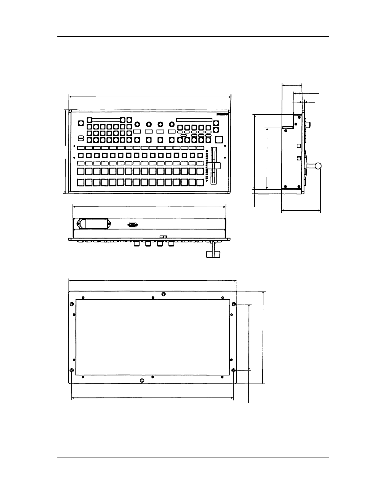
19” Mounting Frame
All dimensions are [ mm ]
482.6
465.1
190.5
265.9
6 Rack units
439
464
240
58
25.8
7
114.5
12.5 215
176.7
Fig. 3: Mechanicak dimensions
Remote Control Panel RSAT23. Installation and Startup
8
Operating Instructions - Rev . 1 / 11.2001
3.3 RACK MOUNTING
Caution:
Mounting the RSAT panel has only be done by qualified service personnel
being informed about the dangers involved!
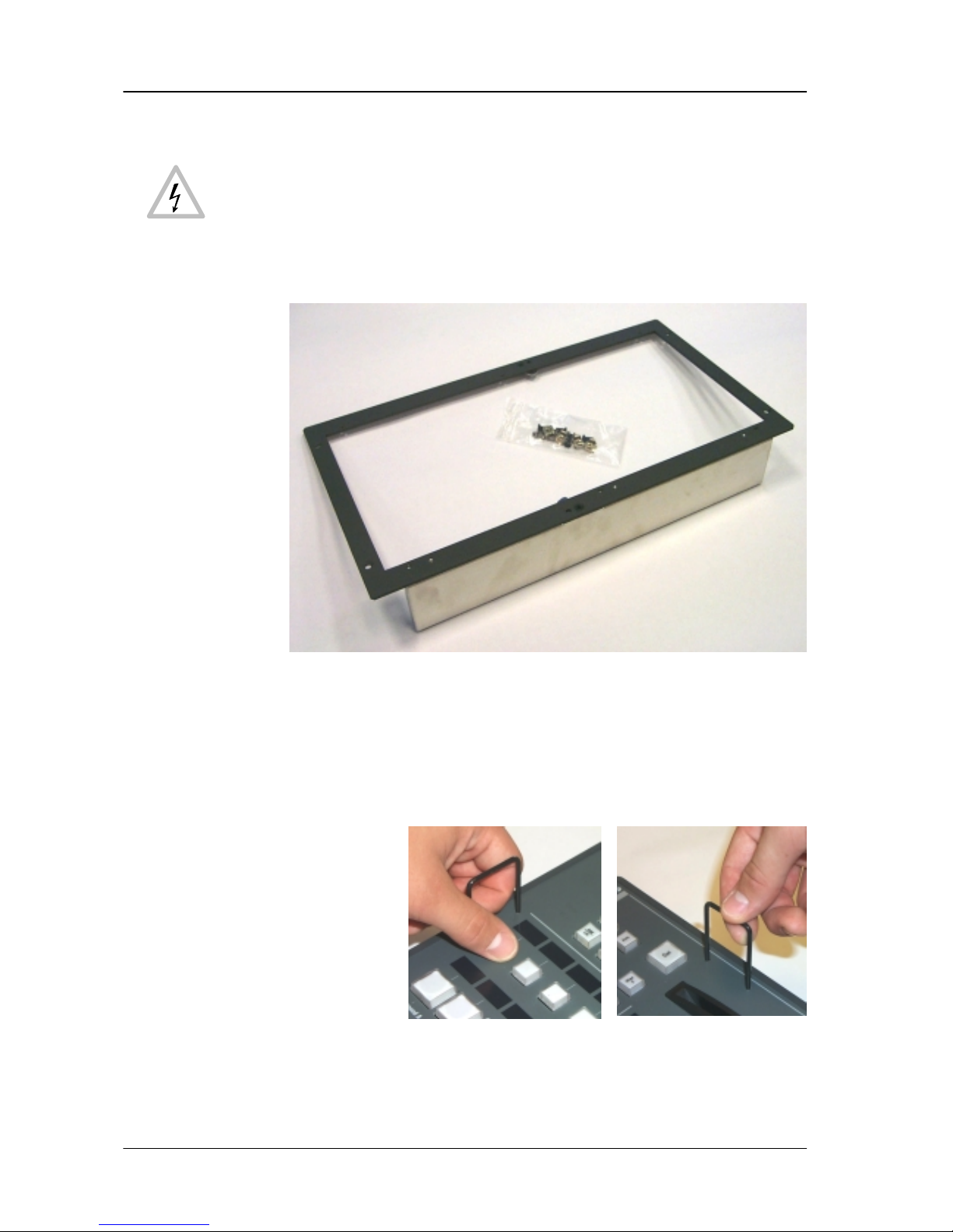
Fig. 4: 19” mounting frame for RSAT2 remote control panel with mounting accessories
Mounting the 19” frame:
Mount the 19” frame into the rack by useing the deliverd accessories
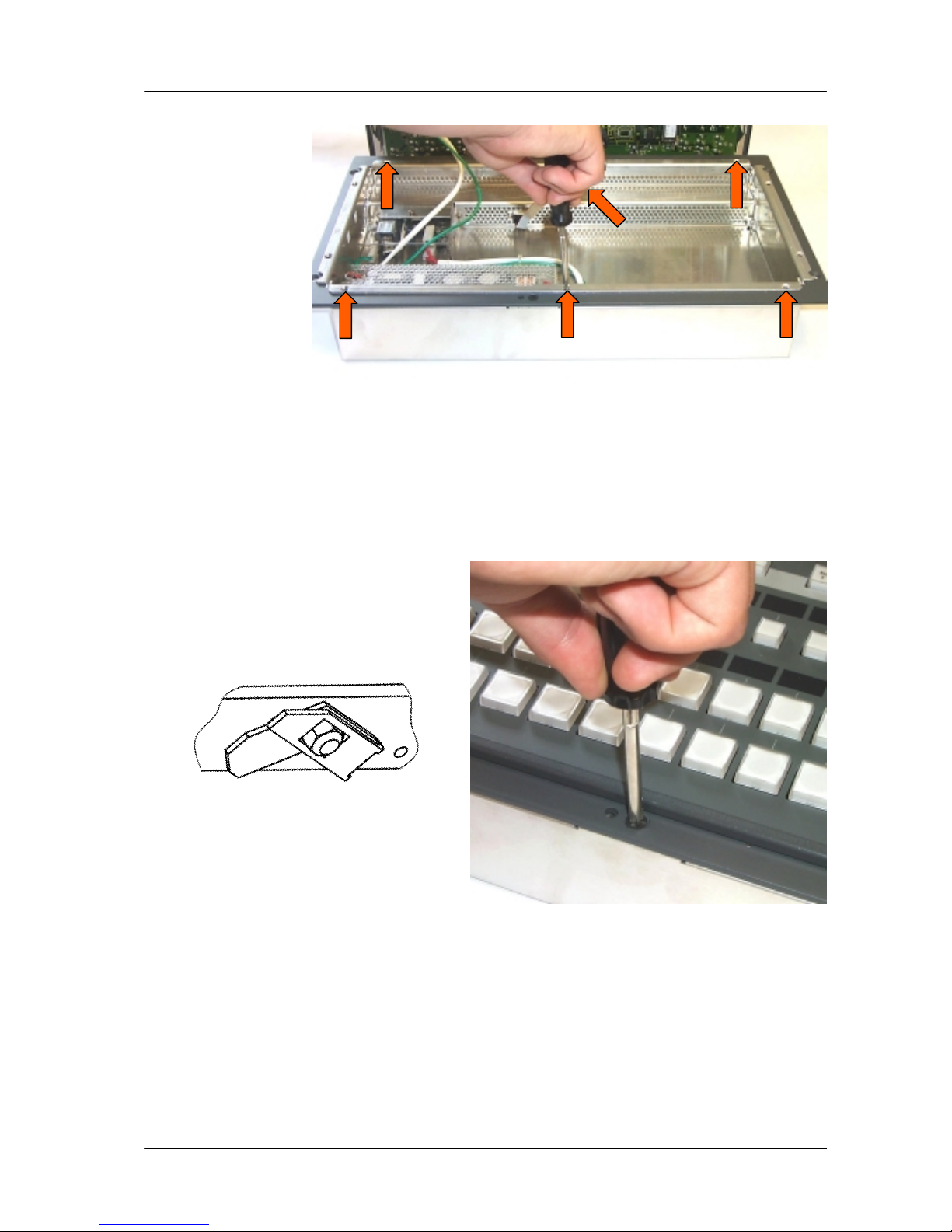
Demount the RSA T2 module by useing the two release tools
(see figures below).
Fig. 5: Release tools
Disconnect control, DC and the ground cable.
Remote Control Panel RSA T2 3. Installation and Startup
Operating Instructions - Rev . 1 / 11.2001
9
Fig. 6: Mounting the RSAT2 case
Put in the RSA T2 case into the 19” frame and fasten it with 6 screws (see acces-
sories).
Connect the cable and put in the RSAT2 module in the case. By pressing, the
module engages independently.
After mounting, please secure the modules with the two locking screws (see
figure below).
Locking mechanism
Fig. 7: Locking the RSAT2 module
 Loading...