

Philips Pronto RFX9400, RFX9400/05, RFX9400/79, RFX9400/37B, RFX9400/37 Starter Manual
...
RFX9400
Starter’s Guide
Manual de inicio
Guide de démarrage
FR
ES
EN


ENGLISH
RFX9400 Starter’s Guide
ESPAÑOLFRANÇAIS
Starter’s Guide
Manual de inicio
Guide de démarrage
RFX9400
1
RFX9400 Starter’s Guide
RFX9400 Starter’s Guide
Contents
Before You Start..............................................2
Unpacking the Extender
...................................3
Configuring the Extender
..................................4
Stand-alone Connection
...............................4
Network Connection
....................................4
Installing the Extender
.....................................6
Connecting the Extender to AV-equipment
.........6
Support..........................................................7
Troubleshooting
..........................................7
Firmware Update
........................................9
Specifications
...............................................10
IFU Approbation / Safety Content RFX9400
...........i
FCC Compliancy
..........................................i
Regulations According to R&TTE
.....................ii
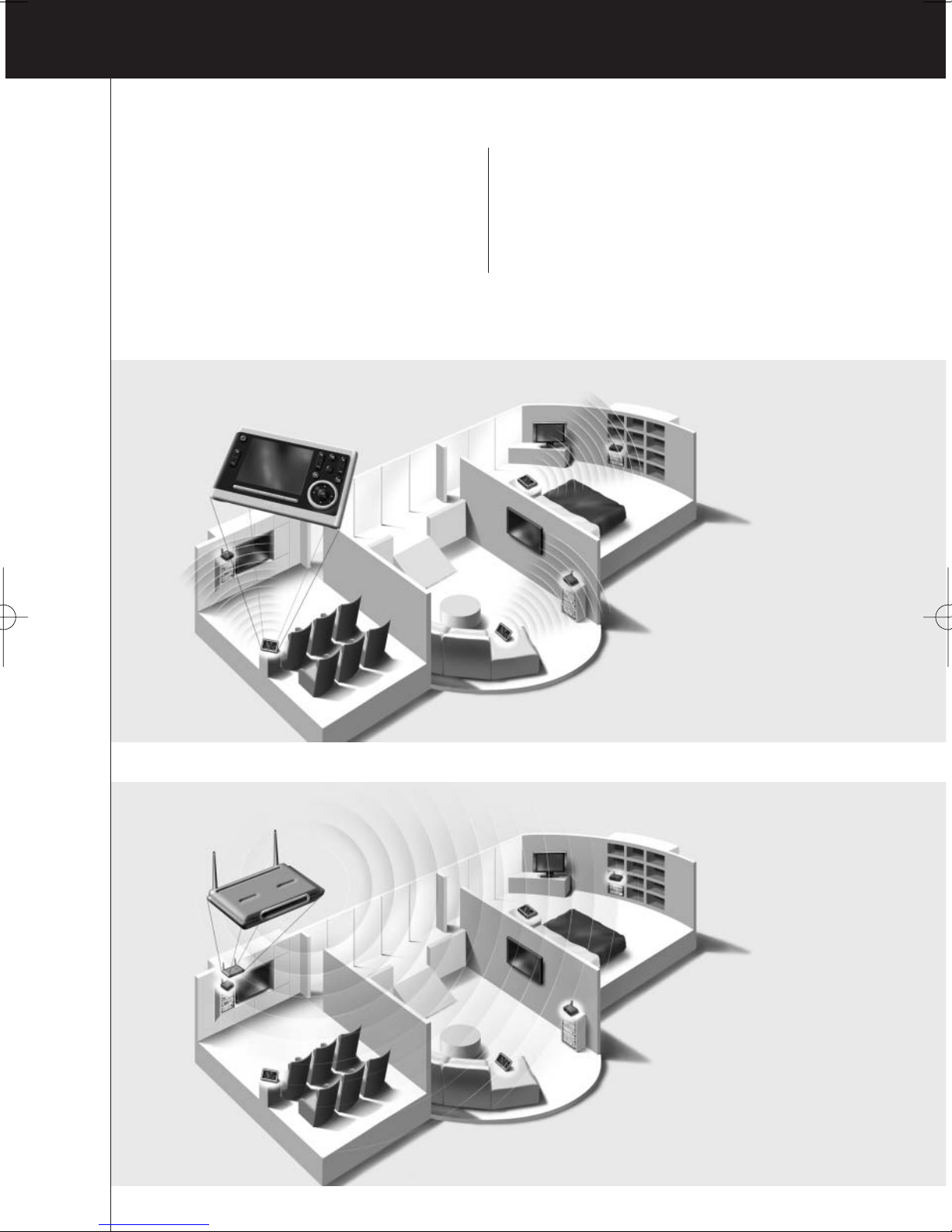
Stand-alone Mode
Network Mode
ENGLISH
2
RFX9400 Starter’s GuideRFX9400 Starter’s Guide
Before You Start
The Pronto Wireless Extender is an important element of the Pronto System and makes it possible
to control AV-equipment via RF in the entire house.
In order to use the Extender in a wireless Pronto Network:
• Configure the Extender: connect it to the PC and use the Configuration Tool.
• Install the Extender: connect it to external AV-equipment, like a TV or receiver.
The Extender can be used in two ways:
Stand-alone Mode
This is the so-called ‘Ad-Hoc Mode’: a router is not required.
Stand-alone Advantages:
• The Extender is easily configured and installed.
• It operates independently from other networks and network settings.
Refer to the chapter ‘Stand-alone Connection’ on page 4 to configure the Extender in Stand-alone
Mode.
Note If you want to use the Escient Fireball audio server in combination with one or more Extenders,
the Extenders have to be configured in Network Mode.
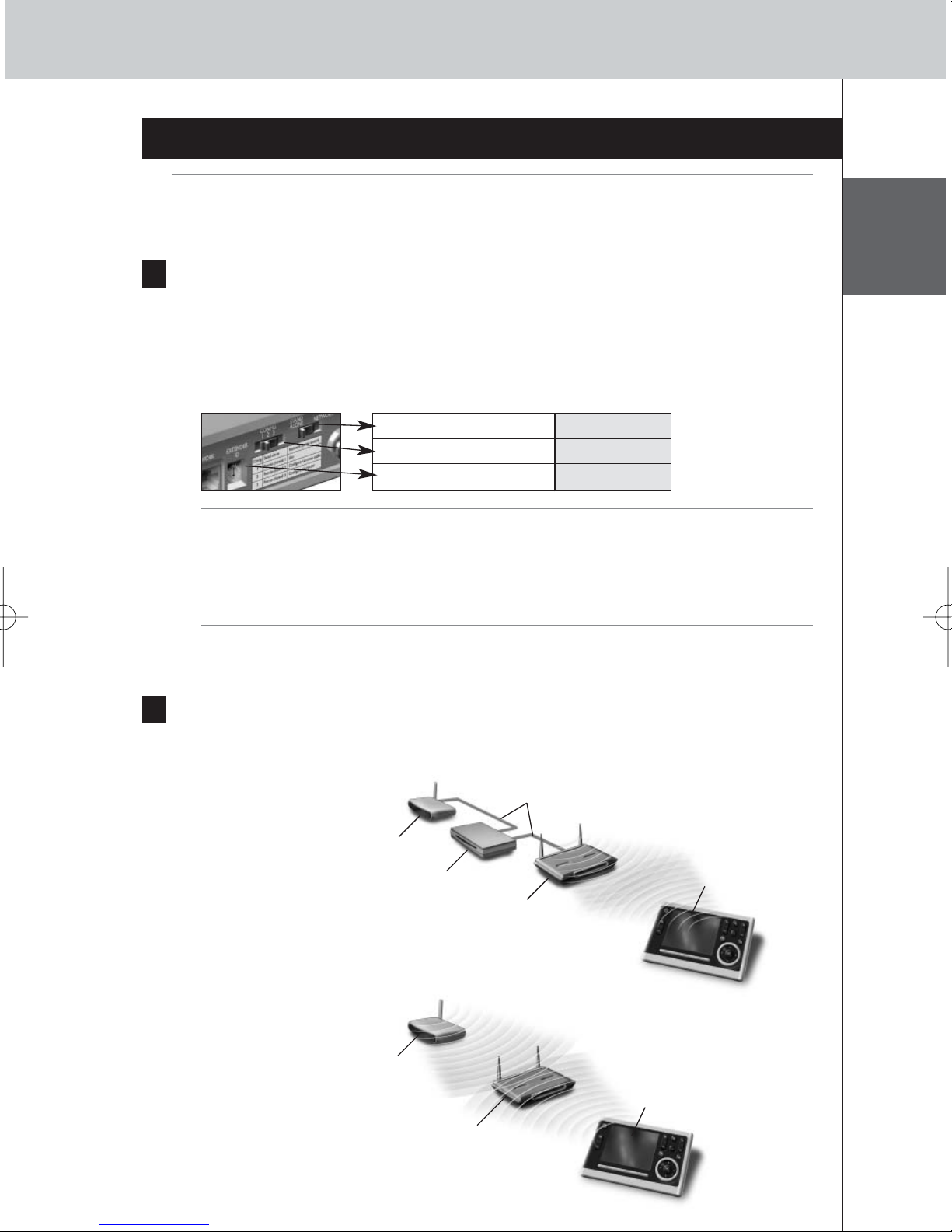
Network Mode
This is the so-called ‘Infrastructure Mode’: the Extender is used in a network with a router.
Network Advantages:
•A network allows the use of repeaters, which enlarges the range of the Pronto System.
• When using a dedicated Pronto Network, the Extender can operate independently from settings
in other networks.
• The Extender in Network Mode can be given a fixed IP address, which increases reliability.
• The network connection can be encrypted.
Refer to the chapter ‘Network Connection’ on page 4 to configure the Extender in Network Mode.
Note An Extender that has been configured in Stand-alone Mode can always be reconfigured for use
in Network Mode and vice versa.
You can use up to 16 different Extenders in the same Pronto Network.
3
RFX9400 Starter’s Guide
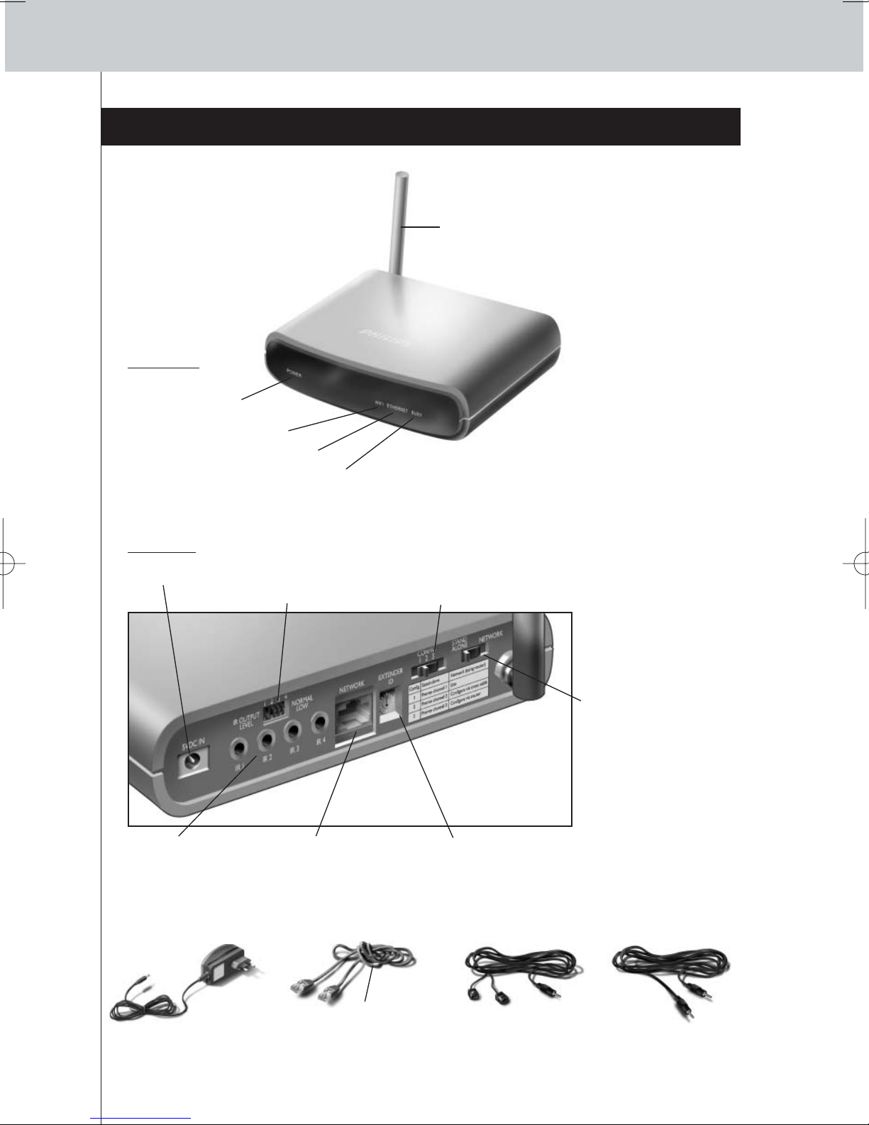
Unpacking the Extender
Pronto Wireless Extender
Front Panel
Antenna
Configuration switch
• In Stand-alone Mode:
changes the RF
channel.
• In Network Mode:
indicates the
connection type.
Power input
4 IR outputs
4 dipswitches for
the IR outputs
Back Panel
Extender ID switchEthernet input
(RJ45)
Stand-alone/
Network switch
2 Dual IR Emitters
2 Mini-jack IR Cables
Power Adapter Configuration Cable
Crossed Ethernet cable
WiFi LED
Ethernet LED
Busy LED
Power LED
ENGLISH
4
RFX9400 Starter’s Guide
Configuring the Extender
Note Before you start configuring the Extender, check if there are any firmware updates available in
the Downloads section on www.pronto.philips.com.
Refer to the chapter ‘Firmware Update’ on page 9 for further details.
Stand-alone Connection
To configure the Stand-alone Extender:
1 Plug in the Extender’s power adapter.
The Extender will start up. When start-up has finished, the Power and WiFi LEDs are green.
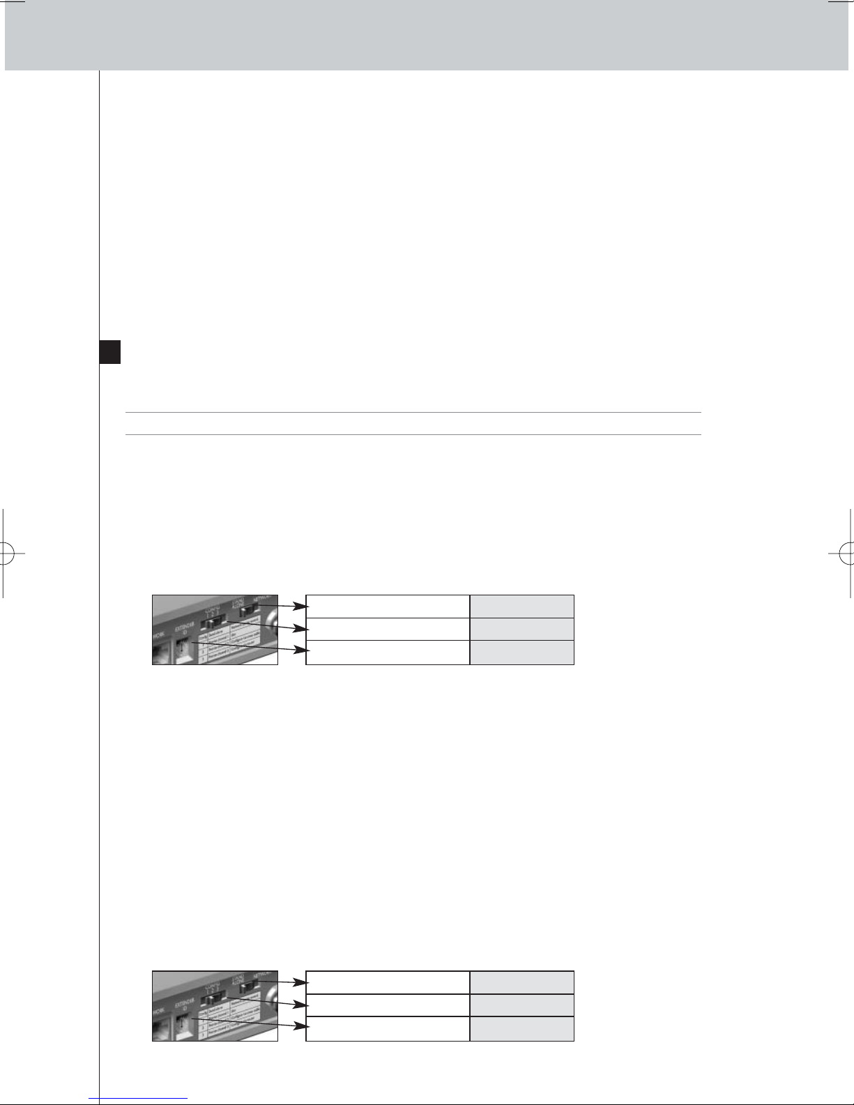
2 Use the default switch settings of the Extender:
Note • If there is already an Extender with ID 0, set the Extender ID switch to an ID that is not
used yet.
• If there is any interference with other products in or around the house, the
Configuration switch can be set to a different RF channel.
•Make sure the same Extender ID and RF channel are used on the Extender and the
Pronto Control Panel.
3 Configure the Control Panel’s configuration file so that the Control Panel can work
with the Extender. For more details, refer to the ProntoEdit Professional Online Help.
Network Connection
In the case of a network connection, the Extender is made part of the wireless Pronto Network.
There are two ways to use the Extender in a network:
• Wired connection
• Wireless connection
Stand-alone/Network Stand-alone
Configuration switch 1
Extender ID 0
Extender
Router
Wireless
Access Point
Straight Ethernet Cable
Extender
Wireless
Access Point
Control Panel
Control Panel
5
RFX9400 Starter’s Guide
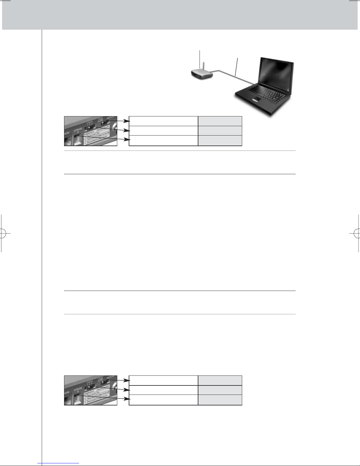
To configure the Network Extender:
1 Connect the Extender to the PC with the
configuration cable (this is the crossed
Ethernet cable enclosed).
2 Set the switches correctly:
Note • If there is already an Extender with ID 0, set the Extender ID switch to an ID that is not
used yet.
•Make sure the same Extender ID is used on the Extender and the Pronto Control Panel.
3 Plug in the Extender’s power adapter.
The Extender will start up. After startup, the Power and Ethernet LEDs are green and the Busy
LED is red/green blinking.
4 Open the browser.
5 Type the IP address of the Extender (printed on the bottom of the Extender) in the
address bar of the browser.
The Configuration Tool opens in the browser.
6 Follow the onscreen instructions and make sure you have the following information at
hand:
• If the Extender will be connected wirelessly to the Pronto Network: the SSID and
encryption settings.
• If the Extender will be operating with a fixed IP address: the IP address, netmask and
default gateway.
Tip To ensure optimal performance, use a dedicated network for all Pronto communication.
This makes the Pronto Network independent from other network traffic and changes in
network settings.
7 Disconnect the Extender from the PC.
8 Connect the Extender to the Pronto Network:
• For a wired connection, connect the Extender to the router by means of a straight Ethernet
cable.
• For a wireless connection, you do not need to connect any more cables.
9 Set the switches correctly:
The Extender will restart. After startup,
• In a wired network connection, the Power and Ethernet LEDs are green and the Busy LED
blinks green when it’s processing a code or a macro from the Control Panel.
• In a wireless network connection, the Power and WiFi LEDs are green and the Busy LED
blinks green when it’s processing a code or a macro from the Control Panel.
Extender Configuration
cable
Stand-alone/Network Network
Configuration switch 2
Extender ID 0
Stand-alone/Network Network
Configuration switch 1
Extender ID 0
ENGLISH
6
RFX9400 Starter’s Guide
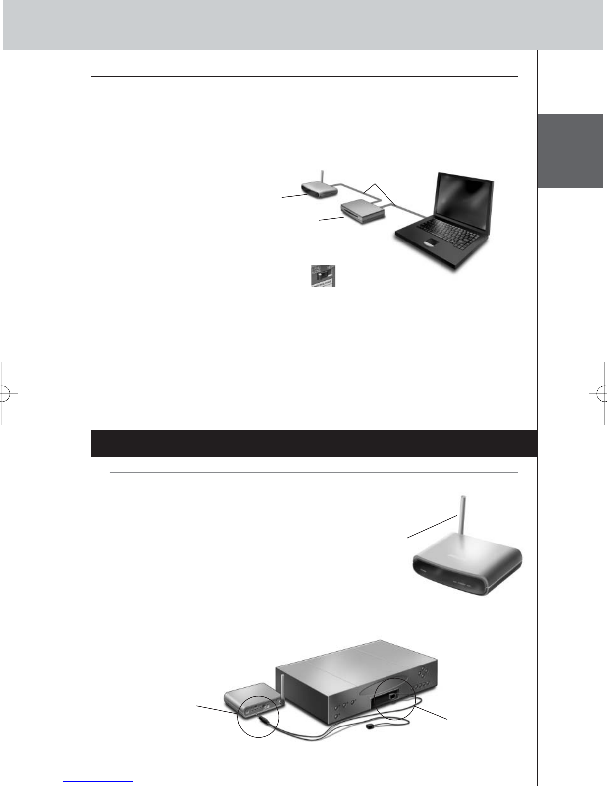
Configuring the Extender through a Router
When the Extender is already installed and connected to external AV-equipment, it is possible to
configure it through a router.
1 Connect the Extender to the router, and the router to the PC, as indicated below.
2 Set the Extender’s Configuration switch to 3.
3 Open the ProntoEdit Professional on the PC.
4 In the Tools menu, select Extender Discovery.
The Extender Discovery tool appears, with a list of all the detected Extenders in the Pronto
Network.
5 Select the Extender that you want to configure and click on the Configure button.
The Configuration Tool opens in the browser.
6 Finalize the configuration, as described in the instructions on page 5.
Installing the Extender
Warning Keep the Extender away from heat sources such as amplifiers.
Before connecting the Extender to external AV-equipment,
make sure that the antenna is placed correctly.
Connecting the Extender to AV-equipment
To connect the Extender to AV-equipment, use one of the following cables enclosed with the
Extender:
•a Dual IR emitter;
Place the antenna
in an upright
position.
Extender
Straight
Ethernet cable
Router
Insert the mini-jack
connector of the
Dual IR emitter in
the IR output of
the Extender.
Attach the
emitter to the
infrared receiver
of the AVcomponent.
7
RFX9400 Starter’s Guide
LEDs
Colors
Ethernet LED WiFi LED Busy LED
The Extender’s IP address is
being determined.
Green blinking
The Extender’s IP address is
being determined.
The Extender is busy processing
a short code or macro from the
Control Panel.
The Extender is functioning
normally.
Green
The Extender is functioning
normally.
The Extender is busy processing
a long macro from the Control
Panel.
–
Red/green blinking
– The Extender is being
configured.
Refer to the topic ‘There is an
IP conflict’ on page 7.
Red
Refer to the topic
‘The Extender cannot
communicate with the
wireless network’ on page 8.
Refer to the topic ‘There are
duplicate Extender IDs’
on page 8.
Refer to the topic ‘The IP address
cannot be determined’ on
page 7.
Red blinking
The Extender is starting up.
Wait until startup has finished.
-or-
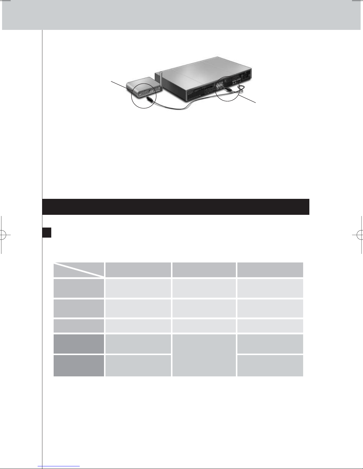
•a mini-jack IR cable.
Adjusting the Power Level of the IR Outputs
At the back of the Extender, there are 4 dipswitches, one for each IR output. Use these dipswitches
to configure the power level of the Dual IR emitters and the mini-jack cables.
For example, flip the dipswitch down to lower the power level when the Extender is connected to
an external IR bus system.
Support
Troubleshooting
What Do the LEDs Indicate?
Insert one mini-jack
connector of the
mini-jack cable in
the IR output of the
Extender.
Insert the other
mini-jack
connector in the
AV-component.
There is an IP conflict
There is another AV-component in the network that is using the same fixed IP address as the
Extender. Change the IP address of the Extender in the Configuration Tool.
If the problem persists, check the router settings.
The IP address cannot be determined
• When using the Extender: make sure that the Extender is connected to the router with a straight
Ethernet cable.

ENGLISH
8
RFX9400 Starter’s Guide
• When configuring the Extender: make sure the PC is not using a fixed IP address but is using
DHCP instead.
•Make sure the router is switched on. If the router is using DHCP, the Extender’s IP address cannot
be determined. Make sure to use the correct network settings on the router.
The Extender cannot communicate with the wireless network
The WiFi LED is red
•Make sure that the Extender is in range of the Wireless Access Point.
•Make sure that you filled in the correct secret in the Configuration Tool.
• Add the Extender’s MAC address to the router’s list of accepted MAC addresses.
The WiFi LED is red blinking
• Check the router’s network settings and make sure that it can operate with the Extender.
• If the LED doesn’t stop blinking, unplug the power adapter, wait a few seconds, and plug it in
again.
Finding the Exact Location of an AV-component’s IR Receiver
1 Remove the protective tape of the Dual IR emitters.
2 Set the Dual IR emitters to the minimal power level, and hold the adhesive side of one
of the emitters 0.4 - 0.8 inch / 1 - 2 cm in front of the AV-component.
3 Make sure the Control Panel is configured to operate with the AV-component.
4 Move the emitter across the front panel of the AV-component, and at the same time,
send commands with the Control Panel to the AV-component.
Take note of when the AV-component reacts to the IR signals of the emitter.
5 When the AV-component reacts, position the emitter in that place.
Operating AV-components with the Extender
The AV-components do not respond to commands from the Extender
• Check if the Busy LED blinks green when you send a command with the Control Panel. If the Busy
LED does not blink, the Extender is not receiving commands from the Control Panel;
•Make sure that the Control Panel is configured correctly in ProntoEdit Professional;
•Make sure that the Extender is configured correctly in the Configuration Tool and connected
properly to the AV-components;
•Make sure that the switches on the Extender are set correctly.
•Make sure that the Wireless Access Point is on and configured correctly.
•Make sure that the Extender is in range of the Wireless Access Point. If the Wireless Access
Point is placed higher or lower than the Extender, place the Extender’s antenna horizontally for
optimum range.
There are duplicate Extender IDs
Using the Extender ID switch, assign a unique ID to each Extender in the same Pronto Network.
Make sure the Control Panel is configured accordingly in ProntoEdit Professional.
You can use up to 16 different Extenders in the same Pronto Network.
9
RFX9400 Starter’s Guide
The Busy LED blinks green when the Control Panel is not in use
This does not mean that something is wrong with the Extender. It merely indicates that the Extender
is being operated by a different Control Panel. When the Busy LED stops blinking, you can use the
Extender again.
Resetting the Extender
This is only necessary when the Extender displays unusual behavior.
To perform a reset, unplug the Extender from the electrical socket. Wait a few seconds, and plug it
in again.
Firmware Update
When an update of the Extender firmware is available, this will be announced on the Philips Pronto
website: www.pronto.philips.com.
Note You can always see the current version of the firmware in the Configuration Tool.
1 Download the new version of the firmware on the PC.
2 Unplug the Extender. The Extender can be updated in the following ways.
Updating the Extender with the configuration cable
1
Connect the Extender to the PC with the configuration cable.
2 Set the switches correctly.
3 Open the browser.
4 Type the IP address of the Extender (printed on the bottom of the Extender) in the
address bar of the browser.
The Configuration Tool opens in the browser.
5 Select Firmware Update in the left navigation pane.
The Firmware Update page opens.
6 Follow the onscreen instructions.
Updating the Extender through a router
If the Extender is already installed and connected to AV-equipment, it may be more convenient to
update it through a router.
1 Connect the Extender to the router, and the router to the PC.
2 Set the switches correctly.
Stand-alone/Network Network
Configuration switch 2
Extender ID 0
Stand-alone/Network Network
Configuration switch 3
Extender ID 0
 Loading...