

Page 1

User Guide
Guía del Usuario
Mode d'emploi
RFX6500
SBC LI910
Page 2

User Guide
Gu’a del usuario
Mode dÕemploi
RF Extender
ENESFR
Page 3

Page 4

User Guide
1
EN
User Guide RF Extender
© 2005 Royal Philips Electronics NV
Remark:
All rights are reserved. Reproduction in whole or in part is prohibited without prior
consent of the copyright owner.
Royal Philips Electronics is not liable for omissions or for technical or editorial
errors in this manual or for damages directly or indirectly resulting from the use of
the RFX6500 / SBC LI910 RF Extender.
The information in this user guide may be subject to change without prior notice.
All brand or product names are trademarks or registered trademarks of their
respective companies or organizations.
RF Extender
User Guide
Page 5

User Guide
2
Contents
Contents 2
How to Use the RF Extender 3
Introduction 3
How to Install the RF Extender 5
How to Connect the RF Extender 5
How to Position the Blaster Unit 6
How to Install the Dual IR Emitters 7
How to Position the Receiver Unit 9
How to Do More 12
How to Set the Extender IDs 12
How to Avoid Interference from Other Prontos 13
How to Use a Longer Connection Cable 13
How to Fine-Tune the Installation Using the Dip Switches 14
How to Turn Off the IR Blaster 14
How to Set the Dual IR Emitter Power Levels 14
Tr oubleshooting 16
Specifications 17
Page 6

User Guide
3
EN
How to Use the RF Extender
Introduction
Infrared (IR) remote controls do not work properly when obstacles between the
remote control and the audio/video devices disturb the operating signal. This
problem can be solved using radio frequency (RF) as a carrier for IR commands.
The Pronto Remote Control, in combination with the RF Extender, can operate
audio/video devices from virtually any location.
The RF Extender consists of two units: a Receiver unit, and a Blaster unit.
The Receiver unit receives RF signals sent out by the Pronto Remote Control. This
unit is connected to the Blaster unit, which converts the signals into IR signals.
The Blaster unit then transmits the IR signals to the audio/video devices.
When the Blaster unit cannot reach all devices or transmits with too much power,
you can use the included Dual IR emitters. You can set up the Dual IR emitters in
two ways:
■ The Dual IR emitters in combination with the Blaster unit.
When there is limited space around the IR receivers of the devices, for
instance in a small closet.
■ The Dual IR emitters instead of the Blaster unit.
When you want to transmit IR signals very accurately, you turn off the Blaster
unit, and control the devices by using the Dual IR emitters alone.
Pronto Receiver unit Blaster unit
RF signals IR signals
Page 7

User Guide
4
The arrangements in the situation shown above can also be combined. You can
control all RF Extenders individually with one or more Pronto Remote Controls.
How to Use the RF Extender
Situation A:
Your devices can be
remotely controlled
when they are not in
the line of sight of the
remote control.
Situation C:
The RF Extender is
placed inside a closet,
a rack or another piece
of furniture together
with your devices.
Situation B:
The RF Extender
controls devices placed
in an adjacent room.
Page 8
User Guide
5
EN
How to Install the RF Extender
Make sure you have the following components: RF Extender Receiver unit,
RF Extender Blaster unit, power adapter, connection cable, Dual IR emitters and
screws.
The installation of the RF Extender consists of 4 main steps:
■ Connecting the RF Extender;
■ Positioning the Blaster unit;
■ Installing the Dual IR emitters;
■ Positioning the Receiver unit.
How to Connect the RF Extender
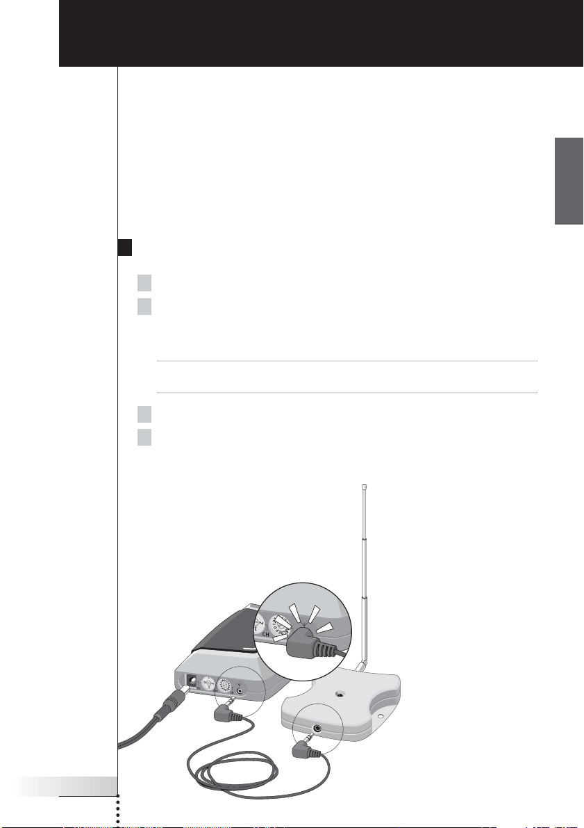
1 Plug the power cable into the Blaster unit.
2 Plug the power adapter into the mains wall socket.
When connected, a red LED on the Blaster unit will start blinking.
After a few seconds, the LED will stop blinking and stay on.
Remark The LED on the Blaster unit will also blink when the Blaster unit sends out
IR signals to the audio/video devices.
3 Plug the connection cable into the Blaster unit until it clicks.
4 Plug the connection cable into the Receiver unit until it clicks.
When connected, the LED on the Receiver unit will stay on for 3 seconds.
Afterwards, the LED will go off.
Page 9

User Guide
6
How to Position the Blaster Unit
For optimal results, the Blaster unit should be positioned horizontally, either facing
up, or facing down.
Make sure to place the Blaster unit in a central position aimed directly at the
audio/video devices. The IR blaster (the dark plastic window on top of the Blaster
unit) in particular should be aimed at the devices, since the IR signals sent out by
the IR blaster must reach the IR receivers of the devices.
For optimal IR reception, position the Blaster unit so the devices are located within
the working range of the Blaster unit, as shown in the picture below.
How to Install the RF Extender
IR reflection area
Page 10
User Guide
7
EN
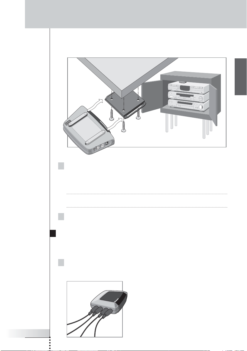
1 Screw the mounting plate to a rack, closet or another piece of
furniture.
Provide sufficient space to connect the power adapter and to slide the Blaster
unit back on.
Note Depending on the surface, it may be possible to attach the mounting plate to
the furniture using a piece of 2-sided tape or velcro.
2 Slide the Blaster unit onto the mounting plate.
How to Install the Dual IR Emitters
The Dual IR emitters can be used in combination with, or as an alternative for the
Blaster unit.
1 Plug the Dual IR emitters into the Blaster unit.
How to Install the RF Extender
Once you have found the best position, you can optionally mount the Blaster unit
onto a piece of furniture using the mounting plate and screws, which are included.
Page 11

User Guide
8
2 Attach the Dual IR emitters to a neighboring surface facing the
IR receiver (for aesthetic purposes or when it is difficult to locate the
IR receiver).
– OR –
Attach the Dual IR emitters directly to the IR receivers of the
audio/video devices.
Make sure the Dual IR emitters are connected properly and that they are placed
within range of the IR receivers.
How to Install the RF Extender
Page 12

User Guide
9
EN
How to Install the RF Extender
How to Position the Receiver Unit
For optimal performance, the Receiver unit should be placed
in a location where there is little or no RF interference.
In most cases, however, you will notice no RF interference.
There may be RF interference when other appliances
(such as WiFi base stations, audio/video devices, microwave
ovens, or wireless telephones) are operated nearby.
The LED on the Receiver unit indicates the
amount of RF interference.
The amount of RF interference present is indicated by the
rate at which the LED blinks and the brightness of the LED
when blinking (a higher rate of blinking and a brighter
light means more RF interference).
To avoid interference, place the Receiver unit in a
position in which the Receiver unit LED blinks and burns
as little as possible.
Remark Do not operate the Pronto Remote Control while positioning the Receiver unit,
since both RF interference and operation of the Pronto Remote Control will cause
the LED of the Receiver unit to blink.
To find the position with the least amount of RF interference, try out the
following steps:
1 Try to create the worst-case scenario, by turning on all devices that
may cause RF interference. If the RF Extender and the Pronto Remote
Control work properly in this scenario, they will certainly work in other
situations.
2 Extend the antenna of the Receiver unit, and direct it upwards.
Page 13
User Guide
10
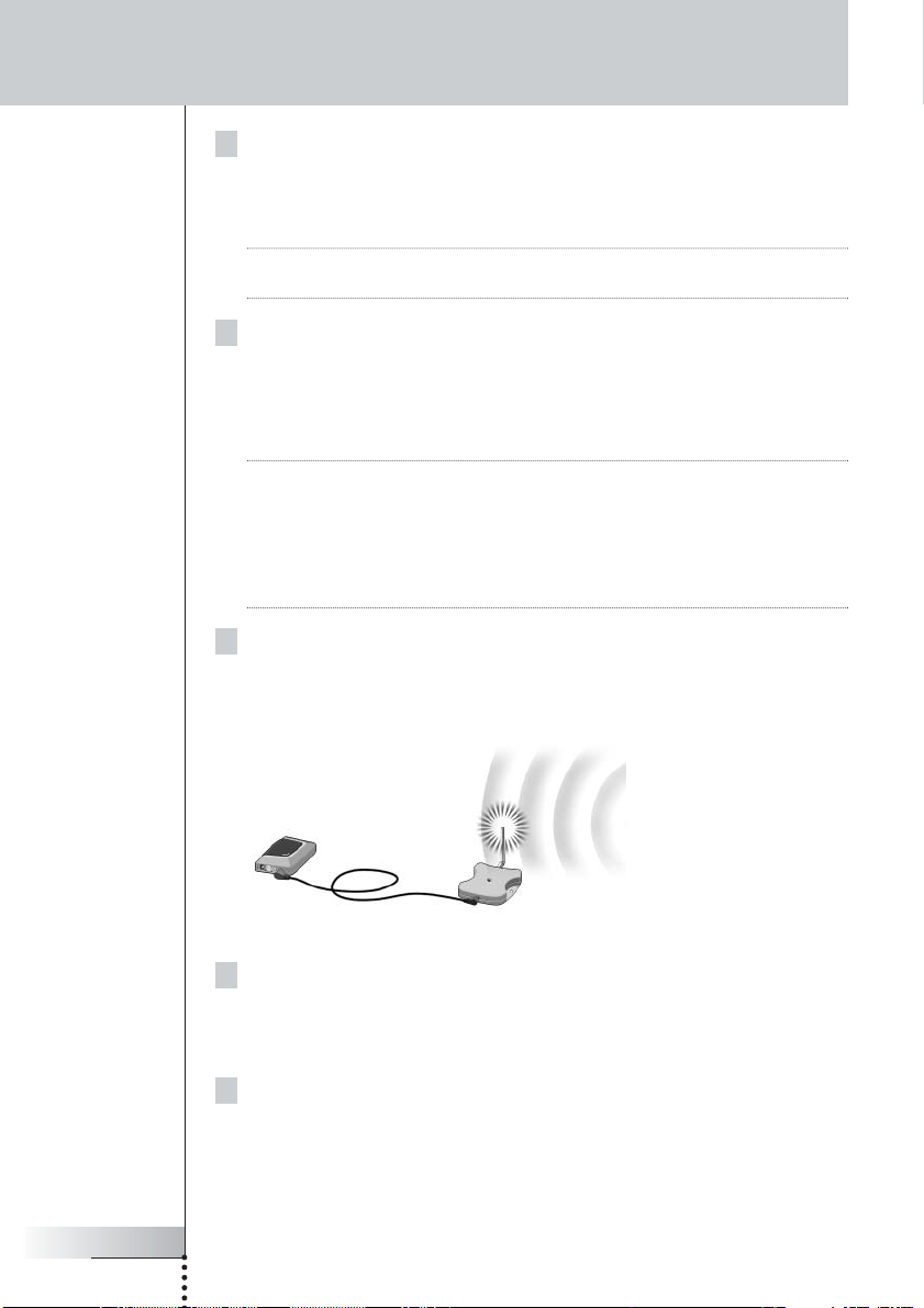
3 Check the LED on the Receiver unit for RF interference.
If the LED does not blink, or blinks only sporadically, position the Receiver unit
there, and continue with step 7. If the LED still blinks, continue with the next
step.
Note When the LED blinks only sporadically, with low light intensity, there are no
problems with RF interference.
4 Try out other positions moving the Receiver unit around, and check the
LED for RF interference.
If the LED does not blink, or blinks only sporadically, mount the Receiver unit in
that place, and continue with step 7. If the LED still blinks, continue with the
next step.
Tip Do not position the Receiver unit:
■ Near audio/video devices, since these devices may cause RF interference.
In particular, keep the Receiver unit away from optical audio/video devices,
such as a DVD player.
■ Near microwave ovens or wireless access points.
■ Inside a metal closet, since metal objects can disturb RF signals.
5 Retract the antenna, keeping it directed upwards.
Retracting in the antenna will cause the Receiver unit to be less sensitive to
interference. It will also decrease the working range of the Pronto Remote
Control.
How to Install the RF Extender
6 Try out other positions moving the Receiver unit around, and check the
LED for RF interference.
If the LED does not blink, or blinks only sporadically, mount the Receiver unit in
that place.
7 Try out your Pronto Remote Control.
When sending commands with the Pronto Remote Control, the LEDs of both
the Receiver unit and the Blaster unit should blink.
Page 14

User Guide
11
EN
8 If necessary, aim the antenna in the direction where the Pronto Remote
Control will be used, to improve the performance in that direction.
How to Install the RF Extender
Once you have found the best position you can optionally mount the Receiver
unit onto a piece of furniture using 2 screws.
Tip Depending on the surface, it may be possible to attach the Receiver unit to the
furniture using a piece of 2-sided tape or velcro. Find the right position and make
sure there is sufficient space.
When the cable for connecting the Receiver unit and the Blaster unit is too short,
you can use a longer cable (see How to Use a Longer Connection Cable p. 13).
Page 15
User Guide
12
How to Set the Extender IDs
The RF Extender can be used in several situations as illustrated in the picture on
p. 4: out of sight, in an adjacent room, or inside a closet.
Since the RF Extender ‘communicates’ with the Pronto Remote Control, you must
set the same Extender ID (identity) on both appliances. The settings depend on
whether you have a single RF Extender or multiple RF Extenders.
Single RF Extender
When you use only one RF Extender, you can accept the default setting for the
Extender ID (ID=0).
■ On the Pronto Remote Control, choose the same Extender ID for each device
controlled by the RF Extender.
Refer to the Pronto User Guide for more information.
Multiple RF Extenders
If you want to operate several of your devices independently, e.g. grouped in
different locations, you need multiple RF Extenders. When using several
RF Extenders, it is important to assign a unique Extender ID to each Blaster unit.
You can assign 16 Extender IDs (from 0 to 9 and from A to F).
For the three RF Extenders in the picture on p. 4, you can set the Extender IDs as
described below:
■ For situation A, set the Extender ID to 0;
■ For situation B, set the Extender ID to 1;
■ For situation C, set the Extender ID to 2.
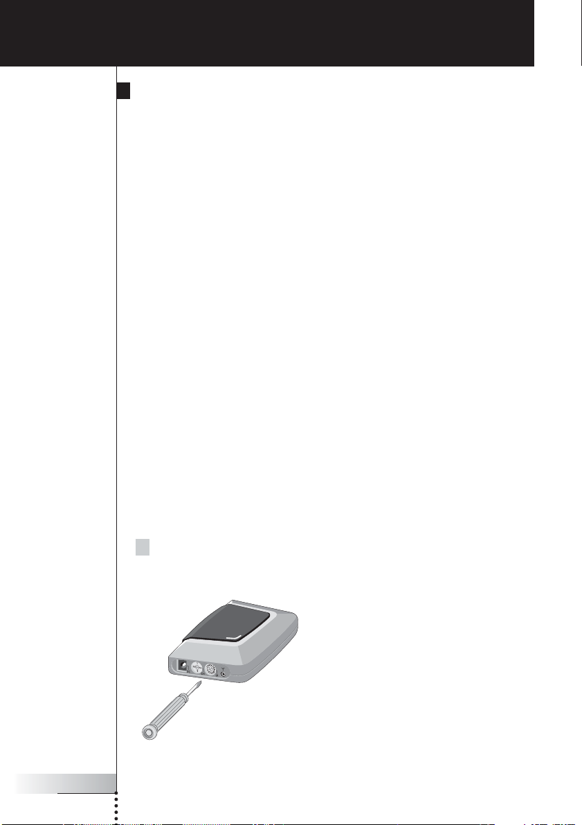
1 Choose an Extender ID for the Blaster unit by turning the ID dial with a
small screwdriver.
How to Do More
Page 16

User Guide
13
EN
2 On the Pronto Remote Control, choose the same Extender ID for each
device controlled by the RF Extender.
Refer to the Pronto User Guide for more information.
3 Try to operate the devices with the Pronto Remote Control.
The red LED on the Blaster unit will blink when the RF Extender receives a
correct command.
Note The LED of the Receiver unit will always blink when RF signals are being
received, even when the extender ID of the Pronto Remote Control and the
Extender ID of the blaster do not match.
The LED of the Blaster unit will blink only when the configuration of the
Pronto Remote Control matches the Extender ID on the Blaster unit.
4 Repeat this procedure for every RF Extender.
How to Avoid Interference from Other Prontos
If the red LED on the Blaster unit is blinking without the Pronto Remote Control
sending commands, the Receiver unit picks up signals from another Pronto Remote
Control on the same channel. You can solve this problem by changing the channel.
You configure the channel on the Pronto Remote Control and on the Blaster unit.
Both channels must be the same. Four channels (CH from 0 to 3) can be assigned.
1 Choose a channel on the Blaster unit by turning the CH dial with a
small screwdriver.
2 On the Pronto Remote Control, choose the same channel.
Refer to the Pronto manual for more information.
3 Try to operate your devices with the Remote Control.
How to Use a Longer Connection Cable
When the connection cable included is not long enough to connect the Receiver
unit to the Blaster unit, you can use a longer cable (up to 20 ft / 6 m). You can
connect the Receiver unit to the Blaster unit with a standard shielded stereo audio
cable with 2.5 mm male jacks on both sides.
How to Do More
Page 17

User Guide
14
How to Fine-Tune the Installation Using the Dip Switches
At the bottom of the Blaster unit, you find 5 dip switches (numbered 1-5). When
you use Dual IR emitters to send the IR signals to the audio/video devices,
configure the dip switches to:
■ Turn the IR blaster on or off (independently from the Dual IR emitters);
■ Configure the power levels of the Dual IR emitters, e.g.:
■ When you configure the Dual IR emitters in wired IR solutions using a
connecting block.
In this case, you can adjust the power levels of the Dual IR emitters.
■ When you use a device that interferes with IR signals, such as a plasma
TV set.
In this case, you can raise the power levels of the Dual IR emitters, since
plasma technology might cause IR interference.
■ When you want to operate 2 identical devices that are placed next to each
other using 2 RF Extenders.
In this case, you can lower the power levels of the Dual IR emitters, in
order to prevent the devices from receiving IR signals intended for another
device.
Switch Switches 1 + 2 Switches 3 + 4 Switch 5
Function Dual IR emitters 1 - 2 Dual IR emitters 3 - 4 IR blaster
Power level Power level On/Off
By default, all dip switches are set to 1 (On).
How to Turn Off the IR Blaster
When you decide to control the audio/video devices with Dual IR emitters only,
you can turn off the IR blaster of the Blaster unit.
■ To turn off the IR blaster, set switch 5 to 0 (Off).
How to Set the Dual IR Emitter Power Levels
You can use dip switches 1 to 4 to set the power level of the Dual IR emitters.
To set the power level:
■ For Dual IR emitters 1 and 2, use switches 1 and 2;
■ For Dual IR emitters 3 and 4, use switches 3 and 4.
You can choose between 4 power levels (0, 1, 2 and 3). By default, power
level 3 is selected for each group of Dual IR emitters.
How to Do More
Page 18

User Guide
15
EN
You can set the power level as indicated below:
Power level Switch 1 Switch 2 Switch 3 Switch 4
(Operating distance)
0 (0.7 m) 0 (Off) 0 (Off) 0 (Off) 0 (Off)
1 (1.5 m) 0 (Off) 1 (On) 0 (Off) 1 (On)
2 (2.0 m) 1 (On) 0 (Off) 1 (On) 0 (Off)
3 (2.5 m - default setting) 1 (On) 1 (On) 1 (On) 1 (On)
Remark The Dual IR emitters still send out IR signals when the power level is set to zero.
The emission is never completely turned off.
How to Do More
Page 19

User Guide
16
The red LED on the Receiver unit blinks when the Pronto Remote
Control is not being used
■ This indicates RF interference. See p. 9.
The red LED on the Blaster unit blinks when the Pronto Remote
Control is not being used
■ This indicates that another Pronto Remote Control is being used in the
proximity of the Receiver unit. See p. 13.
There is no red LED on my Blaster unit
■ Make sure the power adapter is connected properly. See p. 5.
The red LED on the Receiver unit does not blink when connecting
it to the Blaster unit
■ Make sure the power adapter is connected properly to the Blaster unit.
See p. 5.
■ Make sure the connection cable between the Receiver unit and the Blaster
unit is connected properly. See p. 5.
The Dual IR emitters are no longer adhesive
■ Replace the adhesive with a fresh piece of transparent 2-sided tape.
I cannot find the exact location of the device’s IR receiver
■ Set the Dual IR emitters to the minimal power level, and hold one of the
emitters 0.4 - 0.8 inch / 1 - 2 cm in front of the device.
Move the emitter across the front panel, and take note of when the device
reacts to the IR signals of the emitter.
When the device reacts, position the emitter in that place.
■ Check the manual for the device.
If you are still in doubt, contact your supplier or the manufacturer.
Troubleshooting
Page 20

User Guide
17
EN
The specifications and design of this product are subject to change without notice.
Hardware Blaster unit Red LED (continuously on when powered, blinking
during IR emission)
16 IDs and 4 CHs
4 outputs for IR emitters
Input for Receiver unit
Possibility of having multiple RF extenders in one
home not interfering
Positioning: freestanding, mounted horizontally or
hanging up side down
Hardware Receiver unit Red LED (blinking when receiving RF commands and
RF interference)
Output for Blaster unit
RF antenna
Dimensions Blaster unit 4.5 x 3.2 x 1.1 inch (112.9 x 81.2 x 26.8 mm)
Dimensions Receiver unit 3.0 x 2.9 x 0.9 inch (77 x 73 x 23.5 mm)
Dimensions antenna Extended: 0.7 inch (17.7 mm)
Retracted: 0.4 inch (9.7 mm)
Fully rotatable (360°)
Operating temperature 32°F to 122°F (0°C to 50°C)
Infrared (IR) Operating distance: 16.4 ft – 22.9 ft (5-7 meters)
IR frequency range: DC/flash codes, 25kHz-100kHz
Radio Frequency (RF) Operating distance: 147.6 ft (45 m) outdoor
Dual IR emitters Number of IR emitters : up to 8 (4x2), emitters wired in
series
3.5 mm mono mini-plug
Cable length: 10 ft (2.5 meters)
Min. range: 3 ft (75 cm)
Power adapter RFX 6500: 120V / 60 Hz AC Power adapter
(400mA/12V DC adapter, UL-approved)
SBC LI910: 230V / 50 Hz AC Power adapter
(400mA/12V DC adapter, CE-approved)
Accessories Connection cable (standard shielded stereo audio
cable, 2.5 mm male jacks on both sides, up to
20 ft / 6 m)
Dual IR emitters
Power adapter
Mounting kit (Plate and screws)
Specifications
Page 21

Page 22

Guía del usuario
1
ES
Guía del usuario Extensor de RF
© Copyright 2005 Royal Philips Electronics, Interleuvenlaan 72 - 74, 3000 Leuven
(Bélgica).
Observaciones:
Todos los derechos reservados. Queda prohibida la reproducción total o parcial sin
consentimiento previo del propietario del copyright.
Royal Philips Electronics no se hace responsable de las omisiones o errores
técnicos o editoriales que pueda contener este manual, ni de los daños directa o
indirectamente resultantes del uso del extensor de RF RFX 6500 / SBC LI910.
La información de este manual del usuario puede estar sujeta a cambios sin previo
aviso. Todos los nombres de marcas y productos son marcas comerciales o marcas
registradas de sus respectivas compañías u organizaciones.
Extensor de RF
Guía del usuario
Page 23

Guía del usuario
2
Índice de contenido 2
Cómo usar el extensor de RF 3
Introducción 3
Cómo instalar el extensor de RF 5
Cómo conectar el extensor de RF 5
Cómo colocar la unidad Transmisora 6
Cómo instalar los emisores de IR duales 7
Cómo colocar la unidad Receptora 9
Otras operaciones 12
Cómo establecer las identidades del extensor 12
Cómo evitar interferencias de otros mandos a distancia Pronto 13
Cómo usar un cable de conexión más largo 13
Cómo poner a punto la instalación utilizando los conmutadores DIP 14
Cómo apagar el transmisor de IR 14
Cómo ajustar los niveles de potencia de los emisores de IR duales 15
Resolución de problemas 16
Especificaciones 17
Índice de contenido
Page 24

Guía del usuario
3
ES
Introducción
Los mandos a distancia por infrarrojos (IR) no funcionan correctamente si existen
obstáculos entre ellos y los dispositivos de audio/vídeo que alteran la señal
operativa. Este problema puede resolverse fácilmente utilizando las radio-
frecuencias (RF) para la transmisión de comandos de IR. El mando a distancia
Pronto, combinado con el extensor de RF, puede controlar el funcionamiento de
dispositivos de audio/vídeo prácticamente desde cualquier lugar.
El extensor de RF se compone de dos unidades: una unidad Receptora y una
unidad Transmisora. La unidad Receptora recibe las señales de RF enviadas por
el mando a distancia Pronto. Esta unidad está conectada a la unidad Transmisora,
que convierte las señales en señales de IR. A continuación, la unidad Transmisora
transmite las señales de IR a los dispositivos de audio/vídeo.
Cómo usar el extensor de RF
Pronto Unidad
Receptora
Unidad
Transmisora
Señales de RF Señales de IR
Cuando la señal de la unidad Transmisora no llega a todos los dispositivos o se
transmite con excesiva potencia, se pueden utilizar los emisores de IR duales
incluidos. Los emisores de IR duales pueden configurarse de dos maneras
distintas:
■ Los emisores de IR duales en combinación con la unidad Transmisora.
Cuando existe poco espacio alrededor de los receptores IR de los dispositivos,
por ejemplo, en el interior de un armario pequeño.
■ Los emisores de IR duales en lugar de la unidad Transmisora.
Cuando se deseen transmitir señales de IR de gran precisión, deberá
desconectarse la unidad Transmisora y controlar los dispositivos utilizando
únicamente los emisores de IR duales.
Page 25

Guía del usuario
4
Las disposiciones de la situación representada anteriormente también pueden
combinarse. Se pueden controlar todos los extensores de RF individualmente
mediante uno o más mandos a distancia Pronto.
Cómo usar el extensor de RF
Situación A:
Los dispositivos se
pueden controlar
remotamente cuando
no están en el campo
visual del mando a
distancia.
Situación C:
El extensor de RF se
coloca en el interior de
un armario u otro tipo
de mueble junto con
los dispositivos.
Situación B:
El extensor de RF
controla los dispositivos
situados en una
habitación contigua.
Page 26

Guía del usuario
5
ES
Asegúrese de que dispone de los componentes siguientes: unidad Receptora del
extensor de RF, unidad Transmisora del extensor de RF, adaptador de potencia,
cable de conexión, emisores de IR duales y tornillos.
La instalación del extensor de RF consiste en 4 pasos principales:
■ Conexión del extensor de RF.
■ Colocación de la unidad Transmisora.
■ Instalación de los emisores de IR duales.
■ Colocación de la unidad Receptora.
Cómo conectar el extensor de RF
1 Conecte el cable de alimentación a la unidad Transmisora.
2 Conecte el adaptador de corriente a una toma eléctrica.
Cuando esté conectado, en la unidad Transmisora se iluminará un LED rojo que
empezará a parpadear.
A los pocos segundos, el LED dejará de parpadear y permanecerá iluminado.
Observaciones El LED de la unidad Transmisora también parpadeará cuando dicha
unidad envíe señales de IR a los dispositivos de audio/vídeo.
3 Conecte el cable de conexión a la unidad Transmisora (deberá oír un
‘clic’).
4 Conecte el cable de conexión a la unidad Receptora (deberá oír un
‘clic’).
Cuando esté conectado, el LED de la unidad Receptora permanecerá
iluminado durante 3 segundos. A continuación, el LED se apagará.
Cómo instalar el extensor de RF
Page 27

Guía del usuario
6
Cómo colocar la unidad Transmisora
Para obtener resultados óptimos, la unidad Transmisora debe colocarse
horizontalmente, ya sea boca arriba o boca abajo.
Asegúrese de colocar la unidad Transmisora en una posición central, dirigida
directamente a los dispositivos de audio/vídeo. Concretamente el transmisor de IR
(la ventana de plástico oscuro situada en la parte superior de la unidad
Transmisora) deberá estar dirigido hacia los dispositivos, ya que las señales de IR
que envía el transmisor de IR deben llegar a los receptores de IR de los
dispositivos.
Para una recepción óptima de las señales de IR, coloque la unidad Transmisora de
manera que los dispositivos estén situados dentro de su radio de alcance, tal
como se muestra en la imagen siguiente.
Cómo instalar el extensor de RF
Área de reflexión de IR
Page 28

Guía del usuario
7
ES
Una vez hallada la posición óptima, puede fijar la unidad Transmisora a un
mueble utilizando la placa de fijación y los tornillos que se incluyen.
Cómo instalar el extensor de RF
1 Fije la placa a una estantería, un armario u otro tipo de mueble con los
tornillos.
Deje espacio suficiente para conectar el adaptador de corriente y colocar la
unidad Transmisora en ella.
Nota Según la superficie, se puede fijar la placa al mueble mediante una cinta
adhesiva de doble cara o con velcro.
2 Deslice la unidad Transmisora en la placa de fijación.
Cómo instalar los emisores de IR duales
Los emisores de IR duales se pueden utilizar en combinación con la unidad
Transmisora o bien en sustitución de esta.
1 Conecte los emisores de IR duales a la unidad Transmisora.
Page 29

Guía del usuario
8
2 Fije los emisores de IR duales a una superficie cercana encarados
hacia el receptor de IR (con fines estéticos o cuando sea difícil
localizar el receptor de IR).
-o bienConecte directamente los emisores de IR duales a los receptores de IR
de los dispositivos de audio/vídeo.
Asegúrese de que los emisores de IR duales estén correctamente conectados y de
que se hallen dentro del radio de alcance de los receptores de IR.
Cómo instalar el extensor de RF
Page 30

Guía del usuario
9
ES
Cómo colocar la unidad Receptora
Para un rendimiento óptimo, la unidad Receptora deberá
situarse en un lugar en el que no haya prácticamente
ningún tipo de interferencias de RF.
No obstante, en la mayoría de los casos no notará
interferencias de RF.
Pueden producirse interferencias de RF cuando haya cerca
otros aparatos en funcionamiento (como estaciones WiFi,
dispositivos de audio/vídeo, hornos microondas o
teléfonos inalámbricos).
El LED de la unidad Receptora indica la cantidad de
interferencias de RF.
La cantidad de interferencias de RF presentes se indica
mediante la velocidad y el brillo del parpadeo del LED
(a mayor velocidad y brillo, más interferencias de RF).
Para evitar interferencias, coloque la unidad Receptora
en una posición en la que el LED de dicha unidad
parpadee y brille lo menos posible.
Observaciones No utilice el mando a distancia Pronto mientras esté colocando la unidad
Receptora, ya que tanto las interferencias de RF como el propio mando a
distancia Pronto harían que el LED de la unidad Receptora parpadease.
Para hallar la posición con menos interferencias de RF, pruebe lo siguiente:
1 Intente reproducir la peor situación posible conectando todos los
dispositivos que puedan causar interferencias de RF. Si el extensor de
RF y el mando a distancia Pronto funcionan correctamente en dicha
situación, también lo harán en otras situaciones.
2 Extienda la antena de la unidad Receptora hacia arriba.
Cómo instalar el extensor de RF
Page 31

Guía del usuario
10
3 Fíjese en el LED de la unidad Receptora por si se producen
interferencias de RF.
Si el LED no parpadea o lo hace sólo esporádicamente, coloque la unidad
Receptora en ese lugar y siga con el paso 7. Si el LED sigue parpadeando, siga
con el paso siguiente.
Nota Cuando el LED parpadea sólo esporádicamente y con poca intensidad, no
existen problemas de interferencias de RF.
4Pruebe a colocar la unidad Receptora en otras posiciones y
compruebe el LED por si hay interferencias de RF.
Si el LED no parpadea o parpadea sólo esporádicamente, instale la unidad
Receptora en ese lugar y siga con el paso 7. Si el LED sigue parpadeando, siga
con el paso siguiente.
Consejos prácticos
No coloque la unidad Receptora:
■ Cerca de dispositivos de audio/vídeo, puesto que estos dispositivos
pueden producir interferencias de RF. Especialmente, mantenga la unidad
Receptora lejos de dispositivos ópticos de audio/vídeo, como reproductores
de DVD.
■ Cerca de hornos microondas o puntos de acceso inalámbrico.
■ En el interior de un armario metálico, ya que los objetos de metal pueden
alterar las señales de RF.
5 Repliegue la antena manteniéndola hacia arriba.
Si repliega la antena, la unidad Receptora tendrá menor sensibilidad a las
interferencias. También se reducirá el radio de alcance del mando a distancia
Pronto.
Cómo instalar el extensor de RF
6Pruebe a colocar la unidad Receptora en otras posiciones y
compruebe el LED por si hay interferencias de RF.
Si el LED no parpadea, o parpadea sólo esporádicamente, instale la unidad
Receptora en ese lugar.
7Pruebe el mando a distancia Pronto.
Cuando se envíen commandos con el mando a distancia Pronto, los LED de la
unidad Receptora y de la unidad Transmisora deberian parpadean.
Page 32

Guía del usuario
11
ES
8 Si fuera necesario, dirija la antena hacia el lugar donde se utilizará el
mando a distancia Pronto para optimizar su funcionamiento en dicha
dirección.
Cómo instalar el extensor de RF
Una vez localizada la mejor posición, si lo desea, puede fijar la unidad
Receptora a un mueble utilizando 2 tornillos.
Consejos prácticos
Según la superficie, se puede fijar la unidad Receptora al mueble mediante una
cinta adhesiva de doble cara o con velcro. Encuentre la posición correcta y
asegúrese de que hay espacio suficiente.
Si el cable de conexión entre la unidad Receptora y la unidad Transmisora es
demasiado corto, se puede utilizar un cable más largo (véase pág. Cómo usar un
cable de conexión más largo p. 13).
Page 33

Guía del usuario
12
Cómo establecer las identidades del extensor
El extensor de RF puede utilizarse en diversas situaciones, tal como se indica en la
imagen de la pág. 4: fuera del campo de visión, en una habitación contigua o en el
interior de un armario.
Puesto que el extensor de RF se ‘comunica’ con el mando a distancia Pronto, es
necesario establecer la misma identidad de extensor (ID de extensor) en ambos
aparatos. La configuración dependerá de si se dispone de un único extensor de RF
o de varios.
Un único extensor de RF
Cuando utilice únicamente un extensor de RF, podrá aceptar el valor por defecto de
la ID del extensor (ID=0).
■ En el mando a distancia Pronto, seleccione la misma ID de extensor para cada
dispositivo controlado por el extensor de RF.
Para más información, consulte el manual del usuario del mando a distancia
Pronto.
Varios extensores de RF
Si desea controlar varios dispositivos de forma independiente (por ejemplo,
agrupados en varias ubicaciones diferentes), deberá utilizar varios extensores de
RF. Si se utilizan varios extensores de RF, es importante asignar una ID de extensor
exclusiva a cada unidad Transmisora. Puede asignar 16 ID de extensor (de 0 a 9 y
de la A a la F).
Para los tres extensores de RF de la imagen de la pág. 4, puede establecer las ID
de extensor tal y como se describe a continuación:
■ Para la situación A, asigne la ID de extensor 0;
■ Para la situación B, asigne la ID de extensor 1;
■ Para la situación C, asigne la ID de extensor 2.
1 Seleccione una ID de extensor para la unidad Transmisora girando el
selector de ID con un destornillador pequeño.
Otras operaciones
Page 34

Guía del usuario
13
ES
2En el mando a distancia Pronto, seleccione la misma ID de extensor
para cada dispositivo controlado por el extensor de RF.
Para más información, consulte el manual del usuario del mando a distancia
Pronto.
3Pruebe a utilizar el mando a distancia Pronto para controlar sus
dispositivos.
El LED rojo de la unidad Transmisora parpadeará cuando el extensor de RF
reciba un comando correcto.
Nota El LED de la unidad Receptora parpadeará siempre que se reciban señales
de RF, incluso aunque la ID de extensor del mando a distancia Pronto y la ID
de extensor de la unidad Transmisora no coincidan.
El LED de la unidad Transmisora parpadeará sólo si la configuración del
mando a distancia Pronto coincide con la ID de extensor de la unidad
Transmisora.
4 Repita este procedimiento con cada extensor de RF.
Cómo evitar interferencias de otros mandos a distancia
Pronto
Si el LED rojo de la unidad Transmisora parpadea sin que el mando a distancia
Pronto esté enviando ningún comando, la unidad Receptora estará recogiendo las
señales emitidas por otro mando a distancia Pronto del mismo canal. Este
problema puede resolverse cambiando el canal.
Configure el canal del mando a distancia Pronto y el de la unidad Transmisora.
Ambos canales deberán ser el mismo. Pueden asignarse cuatro canales
(CH de 0 a 3).
1 Seleccione un canal para la unidad Transmisora girando el selector CH
con un destornillador pequeño.
2En el mando a distancia Pronto, seleccione el mismo canal.
Para más información, consulte el manual del mando a distancia Pronto.
3Pruebe a utilizar el mando a distancia para controlar sus dispositivos.
Cómo usar un cable de conexión más largo
Si el cable de conexión incluido no es lo suficientemente largo para conectar la
unidad Receptora con la transmisora, puede utilizar un cable más largo (de hasta
6 m). Puede conectar la unidad Receptora a la transmisora utilizando un cable
blindado de audio estéreo estándar con conectores macho de 2,5 mm en ambos
extremos.
Otras operaciones
Page 35

Guía del usuario
14
Cómo poner a punto la instalación utilizando los
conmutadores DIP
En la base de la unidad Transmisora hay 5 conmutadores DIP (numerados del 1 al
5). Si utiliza los emisores de IR duales para enviar señales de IR a dispositivos de
audio/vídeo, configure los conmutadores DIP de la siguiente manera:
■ Encienda el transmisor de IR o apáguelo (independientemente de los emisores
de IR duales).
■ Configure los niveles de potencia de los emisores de IR duales, por ejemplo:
■ Si configura los emisores de IR duales en soluciones de IR no inalámbricas
utilizando un bloque de conexión.
En este caso, se pueden ajustar los niveles de potencia de los emisores de
IR duales.
■ Si utiliza un dispositivo que produce interferencias en las señales de IR,
como un televisor de plasma.
En este caso, se puede elevar el nivel de potencia de los emisores de IR
duales, ya que la tecnología de plasma podría producir interferencias de
IR.
■ Si desea utilizar dos dispositivos idénticos situados uno cerca del otro
mediante el uso de dos extensores de RF.
En este caso, se puede disminuir el nivel de potencia de los emisores de
IR duales a fin de impedir que los dispositivos reciban señales de IR
destinadas a otro dispositivo.
Conmutador Conmutadores 1 + 2 Conmutadores 3 + 4 Conmutador 5
Función Emisores de IR duales 1 - 2 Emisores de IR duales 3 - 4 Transmisor de IR
Nivel de potencia Nivel de potencia Encendido/Apagado
Por defecto, todos los conmutadores DIP están ajustados en la posición 1 (en
funcionamiento).
Cómo apagar el transmisor de IR
Si desea controlar sus dispositivos de audio/vídeo solamente mediante los
emisores de IR duales, puede apagar el transmisor de IR de la unidad Transmisora.
■ Para apagar el transmisor de IR, coloque el conmutador 5 en la posición 0
(apagado).
Otras operaciones
Page 36

Guía del usuario
15
ES
Cómo ajustar los niveles de potencia de los emisores de
IR duales
Puede utilizar los conmutadores DIP del 1 al 4 para establecer el nivel de potencia
de los emisores de IR duales.
Para ajustar el nivel de potencia:
■ Para los emisores de IR duales 1 y 2, utilice los conmutadores 1 y 2.
■ Para los emisores de IR duales 3 y 4, utilice los conmutadores 3 y 4.
Se pueden seleccionar cuatro niveles de potencia distintos (0, 1, 2 y 3).
Por defecto, el nivel de potencia seleccionado para cada grupo de emisores de IR
duales es el 3.
Puede ajustar el nivel de potencia tal como se indica a continuación:
Nivel de potencia Conmutador 1 Conmutador 2 Conmutador 3 Conmutador 4
(distancia operativa)
0 (0.7 m) 0 (apagado) 0 (apagado) 0 (apagado) 0 (apagado)
1 (1.5 m) 0 (apagado) 1 (encendido) 0 (apagado) 1 (encendido)
2 (2.0 m) 1 (encendido) 0 (apagado) 1 (encendido) 0 (apagado)
3 (valor por 1 (encendido) 1 (encendido) 1 (encendido) 1 (encendido)
defecto: 2,5 m)
Observaciones Los emisores de IR duales siguen enviando señales de IR cuando el nivel
de potencia se ha ajustado a cero. La emisión nunca se desactiva
completamente.
Otras operaciones
Page 37

Guía del usuario
16
El LED rojo de la unidad Receptora parpadea cuando no se está
utilizando el mando a distancia Pronto
■ Indica que hay interferencias de RF. Consulte la pág. 9.
El LED rojo de la unidad Transmisora parpadea cuando no se está
utilizando el mando a distancia Pronto
■ Indica que se está utilizando otro mando a distancia Pronto en las
proximidades de la unidad Receptora. Consulte la pág. 13.
En la unidad Transmisora no se ve ningún LED rojo
■ Asegúrese de que el adaptador de corriente esté conectado correctamente.
Consulte la pág. 5.
El LED rojo de la unidad Receptora no parpadea al conectarla a la
unidad Transmisora
■ Asegúrese de que el adaptador de corriente esté conectado correctamente a la
unidad Transmisora. Consulte la pág. 5.
■ Asegúrese de que el cable de conexión entre la unidad Receptora y la unidad
Transmisora esté correctamente conectado. Consulte la pág. 5.
Los emisores de IR duales han perdido su capacidad adhesiva
■ Sustituya el adhesivo por un nuevo pedazo de cinta adhesiva de doble cara.
No puedo encontrar la localización exacta del receptor de IR del
dispositivo
■ Ajuste los emisores de IR duales al nivel de potencia mínimo y coloque uno de
los emisores delante del dispositivo a 1-2 cm de distancia.
Mueva el emisor por el panel delantero y observe la reacción del dispositivo a
las señales de IR del emisor.
Cuando el dispositivo reaccione, coloque el emisor en ese lugar.
■ Consulte el manual del dispositivo.
Si tiene alguna duda, póngase en contacto con su proveedor o con el
fabricante.
Resolución de problemas
Page 38

Guía del usuario
17
ES
Las especificaciones y el diseño de este producto están sujetos a cambios sin
previo aviso.
Unidad transmisora (hardware) LED rojo (iluminado continuamente cuando está en
funcionamiento; parpadeando durante la emisión de IR)
16 ID y 4 CH
4 salidas para emisores de IR
Entrada para la unidad Receptora
Posibilidad de disponer de varios extensores de
RF en una misma vivienda sin que se produzcan
interferencias
Colocación: sin empotrar, montada horizontalmente o
colgando al revés
Unidad receptora (hardware) LED rojo (parpadea cuando recibe comandos de RF y
detecta interferencias de RF).
Salida de la unidad Transmisora
Antena de RF
Dimensiones unidad Transmisora 112,9 x 81,2 x 26,8 mm
Dimensiones unidad Receptora 77 x 73 x 23,5 mm
Dimensiones antena Extendida: 17,7 mm
Replegada: 9,7 mm
Completamente giratoria (360°)
Temperatura operativa de 0°C a 50°C
Infrarrojos (IR) Distancia operativa: de 5 a 7 metros
Margen de frecuencias de IR: códigos DC/flash,
25kHz-100kHz
Radiofrecuencia (RF) Distancia operativa: 45 m en el exterior
Emisores de IR duales Número de emisores de IR: hasta 8 emisores (4x2)
conectados en serie por cable
Miniconector mono de 3,5 mm
Longitud del cable: 2,5 metros
Radio de alcance mínimo: 75 cm
Adaptador de corriente RFX 6500: adaptador de CA de 120 V / 60 Hz
(adaptador de CC de 400 mA / 12 V, aprobado por UL)
SBC LI910: adaptador de CA de 230 V / 50 Hz
(adaptador de CC de 400 mA / 12 V, aprobado por CE)
Accesorios Cable de conexión (cable blindado de audio estéreo
estándar, conectores macho de 2,5 mm en ambos
extremos, hasta 6 m de longitud)
Emisores de IR duales
Adaptador de corriente
Kit de montaje (placa y tornillos)
Especificaciones
Page 39

Page 40

Mode d’emploi
1
FR
Mode d’emploi Prolongateur de signal RF
© Copyright 2004 Royal Philips Electronics, Interleuvenlaan 72 - 74, 3000 Leuven
(Belgique).
Remarque :
Tous les droits sont réservés. Toute reproduction partielle ou totale est interdite
sans l’autorisation préalable du titulaire du droit d’auteur.
Royal Philips Electronics décline toute responsabilité en cas d’omissions, d’erreurs
techniques ou d’édition dans ce mode d’emploi ou de dommages résultant
directement ou indirectement de l’utilisation du Prolongateur de signal
RF RFX6500 / SBC LI910.
Les informations contenues dans ce mode d’emploi peuvent faire l’objet de
modifications sans avis préalable. Tous les noms de marque ou de produit sont des
marques de commerce ou des marques déposées de leurs sociétés ou
organisations respectives.
Prolongateur de signal RF
Mode d’emploi
Page 41

Mode d’emploi
2
Table des matières
Table des matières 2
Comment utiliser le Prolongateur de signal RF ? 3
Introduction 3
Comment installer le Prolongateur de signal RF ? 5
Comment brancher le Prolongateur RF ? 5
Comment positionner le blaster ? 6
Comment installer les émetteurs IR doubles ? 7
Comment positionner le récepteur ? 9
Que faire de plus? 12
Comment définir les ID d’extension ? 12
Comment éviter les interférences avec d'autres télécommandes Pronto ? 13
Comment utiliser un câble plus long ? 13
Comment régler minutieusement l’installation avec des commutateurs DIP ? 14
Comment désactiver le diffuseur infrarouge ? 14
Comment régler le niveau de puissance des émetteurs IR doubles ? 15
Dépannage 16
Spécifications 17
Page 42

Mode d’emploi
3
FR
Comment utiliser le Prolongateur de signal RF ?
Introduction
Les télécommandes à infrarouges (IR) ne fonctionnement pas correctement si des
obstacles empêchent le transfert du signal entre la télécommande et les dispositifs
audio/vidéo. Ce problème peut être résolu grâce à la radiofréquence (RF) qui fait
office d’onde porteuse pour les commandes infrarouges. La télécommande Pronto,
en association avec le Prolongateur de signal RF, peut faire fonctionner
virtuellement les dispositifs audio/vidéo à partir de n’importe quel endroit.
Le Prolongateur de signal RF est composée de deux appareils : un Récepteur et
un Blaster. Le Récepteur reçoit les signaux de RF envoyés par la télécommande
Pronto. Cet appareil est relié au Blaster, lequel convertit les signaux en signaux IR.
Le Blaster transmet les signaux IR aux dispositifs audio/vidéo.
Lorsque le Blaster n’atteint pas tous les dispositifs ou s’il n’est pas assez puissant,
vous pouvez utiliser les émetteurs IR doubles fournis. Vous pouvez les régler de
deux façons :
■ Les émetteurs infrarouges doubles en association avec le Blaster.
Cette configuration s’applique lorsque l’espace est limité autour des
récepteurs IR des dispositifs, par exemple dans un petit placard.
■ Les émetteurs IR doubles à la place du Blaster.
Lorsque vous voulez transmettre des signaux IR très précis, désactivez le
Blaster et commandez les dispositifs en utilisant uniquement les émetteurs IR
doubles.
Pronto Récepteur Blaster
Signaux RF Signaux IR
Page 43

Mode d’emploi
4
Les dispositions proposées pour le cas ci-dessus peuvent également être
combinées. Vous pouvez commander toutes les Prolongateurs RF individuellement
avec une ou plusieurs télécommandes Pronto.
Comment utiliser le Prolongateur de signal RF ?
Situation A :
Vos dispositifs peuvent
être commandés à
distance lorsqu’ils ne
sont pas dans la ligne
de visée de la
télécommande.
Situation C :
Le Prolongateur RF est
placée dans un placard,
un bâti ou un autre
meuble avec vos
dispositifs.
Situation B :
Le Prolongateur RF
commande les
dispositifs placés dans
une pièce voisine.
Page 44

Mode d’emploi
5
FR
Comment installer le Prolongateur de signal RF ?
Vérifiez que vous êtes bien en possession des composants suivants : Récepteur du
Prolongateur RF, Blaster du Prolongateur RF, adaptateur d’alimentation, câble de
connexion, émetteurs IR doubles et vis.
L’installation du Prolongateur RF se décompose en 4 étapes principales :
■ Branchement du Prolongateur RF ;
■ Positionnement du Blaster ;
■ Installation des émetteurs IR doubles ;
■ Positionnement du Récepteur.
Comment brancher le Prolongateur RF ?
1 Raccordez l’adaptateur d’alimentation au Blaster.
2 Raccordez l’adaptateur d’alimentation à la prise secteur.
Une fois que vous avez connecté le Blaster, un voyant DEL se met à clignoter.
Au bout de quelques secondes, il cesse de clignoter et reste fixe.
Remarque Le voyant du Blaster clignote également lorsque ce dernier envoie des
signaux IR vers les dispositifs audio/vidéo.
3Branchez le câble de connexion au Blaster jusqu’à ce qu’un déclic se
fasse entendre.
4 Branchez le câble de connexion au Récepteur jusqu’à ce qu’un déclic
se fasse entendre.
Une fois le Récepteur connecté, le
voyant correspondant reste allumé
pendant 3 secondes.
Il s’éteindra plus tard.
Page 45

Mode d’emploi
6
Comment positionner le blaster ?
Pour obtenir les meilleurs résultats possible, le Blaster doit être installé à
l’horizontale, face orientée vers le haut ou vers le bas.
Veillez à placer le Blaster de façon centrée et orientée vers les dispositifs
audio/vidéo. Le diffuseur infrarouge (la fenêtre en plastique sombre située audessus du Blaster) en particulier doit être orienté vers les dispositifs car les
signaux IR envoyés par le diffuseur infrarouge doivent atteindre les récepteurs IR
des dispositifs.
Pour obtenir une réception optimale des IR, positionnez le Blaster de façon à ce
que les dispositifs soient installés dans sa plage de fonctionnement, comme
indiqué sur l’image ci-dessous.
Comment installer le Prolongateur de signal RF ?
Zone de réflexion des
infrarouges
Page 46

Mode d’emploi
7
FR
1Vissez la plaque sur un bâti, un placard ou un autre meuble.
Laissez suffisamment d’espace pour brancher l’adaptateur d’alimentation et
faire glisser le Blaster.
Remarque En fonction de la surface, il peut être possible de fixer la plaque de
montage au meuble par l’intermédiaire d’un ruban adhésif à double face
ou d’une bande velcro.
2 Faites glisser le Blaster sur la plaque.
Comment installer les émetteurs IR doubles ?
Les émetteurs IR doubles peuvent être utilisés en association avec le Blaster ou à
sa place.
1 Branchez les émetteurs IR doubles au Blaster.
Comment installer le Prolongateur de signal RF ?
Dès que vous avez trouvé la position optimale, vous pouvez éventuellement
installer le Blaster sur un meuble en utilisant la plaque de montage et les vis
fournies.
Page 47

Mode d’emploi
8
2 Fixez les émetteurs IR doubles sur une surface proche orientée vers le
récepteur IR (à des fins esthétiques ou lorsque le récepteur IR est
difficile à localiser).
–ou–
Fixez les émetteurs IR doubles directement sur les récepteurs IR des
dispositifs audio/vidéo.
Vérifiez que les émetteurs sont correctement branchés et qu’ils sont placés à la
portée des récepteurs IR.
Comment installer le Prolongateur de signal RF ?
Page 48

Mode d’emploi
9
FR
Comment positionner le récepteur ?
Pour améliorer au maximum les performances, le
Récepteur doit être placé dans un endroit non ou peu
exposé aux interférences des RF.
Toutefois, vous remarquerez qu’il n’y a généralement pas
d’interférences RF.
Ces interférences sont possibles lorsque d’autres
appareils (des stations de base WiFi, des dispositifs
audio/vidéo, des fours à micro-ondes ou des téléphones
sans fil) fonctionnent à proximité.
Le voyant du Récepteur indique la quantité
d’interférences RF.
La quantité d’interférences RF est signalée par la vitesse à
laquelle le voyant clignote et par la luminosité de ce
dernier (plus la vitesse et la luminosité sont élevées, plus
les interférences RF sont importantes).
Pour éviter les interférences, placez le Récepteur de façon
à ce que le voyant correspondant clignote et s’allume le
moins possible.
Remarque N’utilisez pas la télécommande Pronto lorsque vous positionnez le Récepteur
car les interférences RF et le fonctionnement de la télécommande Pronto
feront clignoter le voyant correspondant.
Pour trouver la position la moins exposée aux interférences RF, suivez la
procédure ci-après :
1 Essayez de créer le pire scénario possible en allumant tous les
appareils susceptibles de provoquer des interférences RF. Si le
Prolongateur RF et la télécommande Pronto fonctionnent correctement
dans cette situation, il est presque certain qu’elles fonctionneront
également dans d’autres situations.
2 Déroulez l’antenne du Récepteur et orientez-la vers le haut.
Comment installer le Prolongateur de signal RF ?
Page 49

Mode d’emploi
10
3 Observez le voyant du Récepteur pour vérifier l’absence
d’interférences RF.
Si le voyant ne clignote pas ou s’il clignote de façon irrégulière, placez le
Récepteur à cet endroit et passez à l’étape 7. Si le voyant continue de
clignoter, passez à l’étape suivante.
Remarque Lorsque le voyant clignote de façon irrégulière et si la lumière émise est
de faible intensité, les interférences RF sont faibles.
4 Essayez d’autres positions en déplaçant le Récepteur et observez le
voyant pour détecter la présence éventuelle d’interférences.
Si le voyant ne clignote pas ou s’il clignote de façon irrégulière, installez le
Récepteur à cet endroit et passez à l’étape 7. Si le voyant continue de
clignoter, passez à l’étape suivante.
Remarque Ne placez pas le Récepteur aux endroits suivants :
■ Près des dispositifs audio/vidéo car ces derniers peuvent provoquer
des interférences RF. Éloignez le Récepteur des dispositifs
audio/vidéo optiques, un lecteur DVD par exemple.
■ Près de fours à micro-ondes ou de points d’accès sans fil.
■ Dans un placard métallique car les objets en métal peuvent
perturber les signaux de radiofréquence.
5 Rentrez l’antenne en la gardant toujours orientée vers le haut.
Si l’antenne est rentrée, le Récepteur sera moins sensible aux interférences.
Cela réduit également la plage de fonctionnement de la télécommande Pronto.
Comment installer le Prolongateur de signal RF ?
6 Essayez d’autres positions en déplaçant le Récepteur et observez le
voyant pour détecter la présence éventuelle d’interférences.
Si le voyant ne clignote pas ou s’il clignote de façon irrégulière, installez le
Récepteur à cet endroit.
7 Essayez votre télécommande Pronto.
Lorsque vous envoyez des commandes, les voyants du Récepteur et du Blaster
doivent clignoter.
Page 50

Mode d’emploi
11
FR
8 Orientez si nécessaire l’antenne dans le sens d’utilisation de la
télécommande Pronto, et ce afin d’améliorer les performances dans
cette direction.
Comment installer le Prolongateur de signal RF ?
Dès que vous avez trouvé la meilleure position, vous pouvez éventuellement
installer le Récepteur sur un meuble en utilisant 2 vis.
Astuce En fonction de la surface, il peut être possible de fixer le Récepteur sur le
meuble en utilisant un ruban adhésif double face ou une bande velcro. Trouvez la
meilleure position et veillez à ce qu’il y ait suffisamment d’espace.
Lorsque le câble qui permet de relier le Récepteur au Blaster est trop court, vous
pouvez utiliser un câble plus long (voir Utilisation d’un câble plus long p. 13).
Page 51

Mode d’emploi
12
Comment définir les ID d’extension ?
Le Prolongateur RF peut être utilisée dans différentes situations comme indiqué
sur le dessin p. 4: hors du champ de vision, dans une pièce voisine ou dans un
placard.
Comme le Prolongateur RF ‘communique’ avec la télécommande Pronto, vous
devez définir le même ID (identification) de Prolongateur sur les deux
appareils. Les paramètres sont différents si vous disposez d’un seul Prolongateur
RF ou si vous en avez plusieurs.
Prolongateur RF unique
Lorsque vous utilisez un seul Prolongateur RF, vous pouvez accepter le paramètre
défini par défaut pour l’ID de Prolongateur (ID=0).
■ Sur la télécommande Pronto, choisissez le même ID de Prolongateur pour
chaque appareil commandé par le Prolongateur RF.
Consultez le mode d’emploi du Pronto pour en savoir plus à ce sujet.
Plusieurs Prolongateurs RF
Si vous voulez faire fonctionner plusieurs dispositifs indépendamment, s’ils sont
placés à différents endroits par exemple, vous avez besoin de plusieurs
Prolongateurs RF. Lorsque vous utilisez plusieurs Prolongateurs RF, il est important
d’attribuer un ID de Prolongateur unique à chaque Blaster. Vous pouvez attribuer
16 ID de Prolongateur (de 0 à 9 et de A à F).
Pour les trois Prolongateurs RF de l’image p. 4, vous pouvez définir les ID de
Prolongateur comme indiqué ci-après :
■ Dans la situation A, réglez l’ID de Prolongateur sur 0 ;
■ Dans la situation B, réglez l’ID de Prolongateur sur 1 ;
■ Dans la situation C, réglez l’ID de Prolongateur sur 2.
1 Choisissez un ID de Prolongateur pour le Blaster en faisant tourner le
cadran ID avec un petit tournevis.
Que faire de plus ?
Page 52

Mode d’emploi
13
FR
2 Sur la télécommande Pronto, choisissez le même ID de Prolongateur
pour chaque dispositif commandé par le Prolongateur RF.
Consultez le mode d’emploi du Pronto pour savoir plus à ce sujet.
3 Essayez de faire fonctionner les dispositifs avec la télécommande
Pronto.
Le voyant rouge du Blaster clignote lorsque le Prolongateur RF reçoit une
commande correcte.
Remarque Le voyant du Récepteur continue de clignoter à la réception de signaux
RF, même lorsque l’ID de Prolongateur de la télécommande Pronto ne
correspond pas à l’ID de Prolongateur du Blaster.
Le voyant du Blaster clignote uniquement lorsque la configuration de la
télécommande Pronto correspond à l’ID de Prolongateur du Blaster.
4 Répétez cette procédure pour chaque Prolongateur RF.
Comment éviter les interférences avec d’autres
télécommandes Pronto ?
Si le voyant rouge du Blaster clignote alors que la télécommande Pronto
n’envoie aucune commande, cela signifie que le Récepteur reçoit les signaux
d’une autre télécommande Pronto sur le même canal. Vous pouvez résoudre ce
problème en changeant de canal.
Configurez le canal sur la télécommande Pronto et sur le Blaster. Les deux canaux
doivent être identiques. Quatre canaux (CH de 0 à 3) peuvent être attribués.
1 Choisissez un canal sur le Blaster en faisant tourner le cadran CH avec
un petit tournevis.
2 Sur la télécommande Pronto, choisissez le même canal.
Consultez le mode d’emploi de la télécommande Pronto pour en savoir plus à
ce sujet.
3 Essayez de faire fonctionner vos dispositifs avec la télécommande.
Comment utiliser un câble plus long ?
Lorsque le câble de connexion n’est pas assez long pour raccorder le Récepteur au
Blaster, vous pouvez utiliser un câble plus long (jusqu’à 6 m). Vous pouvez
raccorder le Récepteur au Blaster avec un câble audio stéréo à paires torsadées
blindées et des fiches mâles de 2,5 mm aux deux extrémités.
Que faire de plus ?
Page 53

Mode d’emploi
14
Comment régler minutieusement l’installation avec
des commutateurs DIP ?
Au-dessous du Blaster, vous trouverez 2 commutateurs DIP (numérotés de 1 à 5).
Lorsque vous utilisez des émetteurs IR doubles pour envoyer les signaux IR vers les
dispositifs audio/vidéo, configurez les commutateurs de façon à :
■ Activer ou désactiver le diffuseur infrarouge (indépendamment des émetteurs
IR doubles) ;
■ Configurer les niveaux de puissance des émetteurs IR doubles, par exemple :
■ Lorsque vous configurez les émetteurs IR doubles des solutions IR câblées
en utilisant un bloc de connexion.
Dans ce cas, vous pouvez régler les niveaux de puissance des émetteurs IR
doubles.
■ Lorsque vous utilisez un dispositif à l’origine d’interférences IR tel qu’un
écran plasma.
Dans ce cas, vous pouvez augmenter les niveaux de puissance des
émetteurs IR doubles car la technologie plasma peut provoquer des
interférences IR.
■ Lorsque vous voulez faire fonctionner 2 dispositifs identiques placés tout
près l’un de l’autre en utilisant 2 Prolongateurs RF.
Dans ce cas, vous pouvez réduire les niveaux de puissance des émetteurs
IR doubles, et ce afin d’éviter que les signaux IR se soient envoyés vers un
autre appareil que celui visé.
Commutateur Commutateurs 1 + 2 Commutateurs 3 + 4 Commutateur 5
Fonction Émetteurs IR doubles 1-2 Émetteurs IR doubles 3-4 Blaster IR
Niveau de puissance Niveau de puissance Activé/Désactivé
Tous les commutateurs DIP sont par défaut réglés sur 1 (Activé).
Comment désactiver le diffuseur infrarouge ?
Lorsque vous décidez de commander les dispositifs audio/vidéo avec des
émetteurs IR doubles uniquement, vous pouvez désactiver le diffuseur infrarouge
du Blaster.
■ Pour désactiver le diffuseur infrarouge, changez le commutateur de 5 sur 0.
Que faire de plus ?
Page 54

Mode d’emploi
15
FR
Comment régler le niveau de puissance des émetteurs IR
doubles ?
Vous pouvez utiliser les commutateurs DIP 1 à 4 pour régler le niveau
d’alimentation des émetteurs IR doubles.
Pour régler le niveau de puissance :
■ Pour les émetteurs IR doubles 1 et 2, utilisez les commutateurs 1 et 2.
■ Pour les émetteurs IR doubles 3 et 4, utilisez les commutateurs 3 et 4.
Vous pouvez choisir 4 niveaux de puissance (0, 1, 2 et 3). Le niveau de puissance 3
est sélectionné par défaut pour chaque groupe d’émetteurs IR doubles.
Vous pouvez régler le niveau de puissancecomme indiqué ci-après :
Niveau de puissance Commutateur Commutateur Commutateur Commutateur
(distance de 1234
fonctionnement)
0 (0.7 m) 0 (Désactivé) 0 (Désactivé) 0 (Désactivé) 0 (Désactivé)
1 (1.5 m) 0 (Désactivé) 1 (Activé) 0 (Désactivé) 1 (Activé)
2 (2.0 m) 1 (Activé) 0 (Désactivé) 1 (Activé) 0 (Désactivé)
3 (2,5 m - paramètre 1 (Activé) 1 (Activé) 1 (Activé) 1 (Activé)
défini par défaut)
Remarque Les émetteurs infrarouges doubles continuent d’envoyer des signaux
infrarouges lorsque le niveau de puissance est réglé sur zéro. L’émission
n’est jamais complètement nulle.
Que faire de plus ?
Page 55

Mode d’emploi
16
Le voyant rouge du Récepteur clignote alors que la télécommande
Pronto n’est pas utilisée
■ Ceci indique la présence d’interférences RF. Reportez-vous à la p. 9.
Le voyant rouge du Blaster clignote alors que la télécommande
Pronto n’est pas utilisée
■ Ceci indique qu’une autre télécommande Pronto est utilisée à proximité du
Récepteur. Reportez-vous à la p. 13.
Aucun voyant rouge ne s’allume sur le Blaster
■ Vérifiez que l’adaptateur d’alimentation est correctement branché. Reportez-
vous à la p. 5.
Le voyant rouge du Récepteur ne clignote pas lorsqu’il est
connecté au Blaster
■ Vérifiez que l’adaptateur d’alimentation est correctement branché au Blaster.
Reportez-vous à la p. 5.
■ Vérifiez que le câble de connexion qui relie le Récepteur au Blaster est
correctement branché. Reportez-vous à la p. 5.
Les émetteurs IR doubles ne collent plus
■ Remplacez l’adhésif par un nouveau ruban double face.
Je ne parviens pas à trouver l’emplacement qui convient au
récepteur IR du dispositif
■ Réglez les émetteurs IR doubles au niveau de puissance minimum et
maintenez l’un des émetteurs à 1-2 cm de l’avant du dispositif.
Déplacez l’émetteur devant le panneau avant et observez le moment où
l’appareil réagit aux signaux IR de l’émetteur.
Lorsque le dispositif réagit, installez l’émetteur à cet endroit.
■ Reportez-vous au mode d’emploi du dispositif.
Si vous avez encore des doutes, contactez votre fournisseur ou le fabricant.
Dépannage
Page 56

Mode d’emploi
17
FR
Les spécifications et la conception de ce produit peuvent être modifiées sans
préavis.
Blaster Voyant rouge (il est allumé lorsque l’appareil est en
marche et clignote pendant l’émission d’IR)
16 ID et 4 CH
4 sorties pour les émetteurs IR
Entrée du Récepteur
Possibilité d’installer plusieurs Prolongateurs RF dans
une même maison sans interférences
Position : sur pied, à l’horizontale ou suspendu face
vers le bas
Récepteur Voyant rouge (il clignote pendant la réception des
commandes et des interférences RF)
Sortie du Blaster
Antenne RF
Dimensions du Blaster 112,9 x 81,2 x 26,8 mm
Dimensions du Récepteur 77 x 73 x 23,5 mm
Dimensions de l’antenne Déroulée : 17,7 mm
Rétractée : 9,7 mm
Pivote à 360°
Température de fonctionnement 0°C à 50°C
Infrarouges (IR) Distance de fonctionnement : 5-7 mètres
Bande de radiofréquences : codes flash/CC,
25kHz-100kHz
Radiofréquence (RF) Distance de fonctionnement : 45 m à l’extérieur
Émetteurs IR doubles Nombre d’émetteurs IR : jusqu’à 8 (4x2) émetteurs
câblés en série
Mini-fiche mono de 3,5 mm
Longueur du câble : 2,5 mètres
Plage minimum : 75 cm
Adaptateur d’alimentation RFX 6500 : 120 V / 60 Hz Adaptateur d’alimentation c.a.
(adaptateur c.c. 400 mA/12 V, homologué UL)
SBC LI910 : adaptateur d’alimentation c.a. 230 V /
50 Hz (adaptateur c.c. 400 mA/12 V, homologué CE)
Accessoires Câble de connexion (câble audio stéréo à paires
torsadées blindées, fiches mâles de 2,5 mm aux deux
extrémités, jusqu’à 6 m)
Émetteurs infrarouges doubles
Adaptateur d’alimentation
Kit de montage (plaque et vis)
Spécifications
Page 57

RFX6500-SBCLI910
FCC Compliancy
This device complies with Part 15 of the FCC Rules. Operation is subject to the
following two conditions:
■ This device should not cause harmful interference.
■ This device must accept any interference received, including interference that may
cause undesired operation.
This equipment has been tested and found to comply with the limits for a Class B digital
device, pursuant to part 15 of the FCC rule and ICES 003 in Canada.
These limits are designed to provide reasonable protection against harmful interference
in residential installations. This equipment generates, uses, and can radiate radio
frequency energy and, if not installed and used in accordance with the instructions, may
cause harmful interference to radio communications.
However, there is no guarantee that interference will not occur in a particular
installation. If the equipment does cause harmful interference to radio or television
reception, which can be determined by turning thee equipment off and on, the user is
encouraged to try to correct the interference by using one or more of the following
measures:
■ Reorient or relocate the receiving antenna.
■ Increase the separation between the equipment and receiver.
■ Connect the equipment into to an outlet on a different circuit from the receiver.
■ Consult the dealer or an experienced radio/TV technician for help.
CAUTION: User changes or modifications not expressly approved by the party responsible for
compliance may void the user’s authority to operate the equipment.
Notice for Canada / Remarque pour le Canada
This Class B digital apparatus complies with Canadian ICES-003.
Cet appareil numérique de la Classe B est conforme à la norme NMB-003 du Canada.
CE Regulations According to R&TTE
Declaration of Conformity
Hereby, Philips Consumer Electronics, Business Line Home Control, Interleuvenlaan
74-82, 3001 Leuven, Belgium declares under his responsibility that the RF extender
SBCLI910 is in compliance with the essential requirements and other relevant provisions
of Directive 1999/5/EC:
■ EMC: ETSI EN 301 489-1 and ETSI EN 301 489-3
■ Safety: IEC 60065
This device complies also to the WEEE Directive 2002/96/EC
Name & Signature,
Heysse Gert
Approbation & Safety Manager
Date:1-09-2005
Page 58

RFX6500-SBCLI910
Note: for Europe only
Disposal of Your Old Product
Your product is designed and manufactured with high quality materials
and components, which can be recycled and reused. Please inform
yourself about the local separate collection system for electrical and
electronic products, including those marked by following symbol:
Finnish Philips Consumer Electronics, Business Line Home Control vakuuttaa täten että SBC LI910
tyyppinen laite on direktiivin 1999/5/EY oleellisten vaatimusten ja sitä koskevien direktiivin
muiden ehtojen mukainen.
Dutch Hierbij verklaart, Philips Consumer Electronics, Business Line Home Control dat het toestel
SBC LI910 in overeenstemming is met de essentiële eisen en de andere relevante bepalingen van
richtlijn 1999/5/EG.
French Par la présente, Philips Consumer Electronics, Business Line Home Control, déclare que l’appareil
SBC LI910 est conforme aux exigences essentielles et aux autres dispositions pertinentes de la
directive 1999/5/CE
Swedish Härmed intygar, Philips Consumer Electronics, Business Line Home Control, att denna SBC LI910
står I överensstämmelse med de väsentliga egenskapskrav och övriga relevanta bestämmelser
som framgår av direktiv 1999/5/EG.
Danish Undertegnede Philips Consumer Electronics, Business Line Home Control erklærer herved, at
følgende udstyr SBC LI910 overholder de væsentlige krav og øvrige relevante krav i direktiv
1999/5/EF
German Hiermit erklärt Philips Consumer Electronics, Business Line Home Control die Übereinstimmung
des Gerätes SBC LI910 mit den grundlegenden Anforderungen und den anderen relevanten
Festlegungen der Richtlinie 1999/5/EG.
Greek ΜΕΤΗΝ ΠΑΡΟΥΣΑ Philips Consumer Electronics, Business Line Home Control ∆ΗΛΩΝΕΙ ΟΤΙ
SBC LI910 ΣΥΜΜΟΡΦΩΝΕΤΑΙ ΠΡΟΣΤΙΣ ΟΥΣΙΩ∆ΕΙΣ ΑΠΑΙΤΗΣΕΙΣ ΚΑΙ ΤΙΣΛΟΙΠΕΣ
ΣΧΕΤΙΚΕΣ ∆ΙΑΤΑΞΕΙΣΤΗΣ Ο∆ΗΛΙΑΣ 1999/5/ΕΚ.
Italian Con la presente Philips Consumer Electronics, Business Line Home Control dichiara che questo
SBC LI910 è conforme ai requisiti essenziali ed alle altre disposizioni pertinenti stabilite dalla
direttiva 1999/5/CE.
Spanish Por medio de la presente, Philips Consumer Electronics, Business Line Home Control, declara que
el SBC LI910 cumple con los requisitos esenciales y cualesquiera otras disposiciones aplicables o
exigibles de la Directiva 1999/5/CE
Portuguese Philips Consumer Electronics, Business Line Home Control declara que este SBC LI910 está
conforme com os requisitos essenciais e outras disposições da Directiva 1999/5/CE.
Page 59

Notes - Notas - Notes
Page 60

Notes - Notas - Notes
Page 61

Notes - Notas - Notes
Concept and realisation of the Guide:
The Human Interface Group
De Regenboog 11, 2800 Mechelen (Belgium)
http://www.higroup.com
3104 205 3384.1
Page 62

 Loading...