

Page 1

BiPAP® Focus™ Ventilator
SERVICE MANUAL
REF 1029568 Rev A
Page 2

Copyright © 2006. Respironics, Inc.
ALL RIGHTS RESERVED.
This work is protected under Title 17 of the United States copyright code and is the sole property of Respironics.
No part of this document may be copied or otherwise reproduced, or stored in any electronic information
retrieval system, except as specifically permitted under United States copyright law, without the prior written
consent of Respironics.
In the U.S. and Canada
Respironics California, Inc.
2271 Cosmos Court
Carlsbad, CA 92011
USA
1-800-345-6443
For Technical support, contact:
Respironics, Inc. Customer Service
Within the U.S.A. 1-800-345-6443
Outside the U.S.A. 724-387-4000
Facsimile 724-387-5012
service@respironics.com
II BiPAP® Focus™ Ventilator Service Manual © Respironics, Inc. REF 1029568 Rev A
Page 3

Table of Contents
1. Introduction and Intended Use. . . . . . . . . . . . . . . . . . . . . . . . . . . . 1-1
Recommended Tools and Test Equipment . . . . . . . . . . . . . . . . . . . . . . . . . . . . 1-2
Where to Go for Help . . . . . . . . . . . . . . . . . . . . . . . . . . . . . . . . . . . . . . . . . . . 1-3
2. Warnings and Cautions . . . . . . . . . . . . . . . . . . . . . . . . . . . . . . . . 2-1
Warnings . . . . . . . . . . . . . . . . . . . . . . . . . . . . . . . . . . . . . . . . . . . . . . . . . . . 2-1
Cautions . . . . . . . . . . . . . . . . . . . . . . . . . . . . . . . . . . . . . . . . . . . . . . . . . . . . 2-2
Notes . . . . . . . . . . . . . . . . . . . . . . . . . . . . . . . . . . . . . . . . . . . . . . . . . . . . . . 2-3
3. Theory of Operation. . . . . . . . . . . . . . . . . . . . . . . . . . . . . . . . . . . 3-1
. . . . . . . . . . . . . . . . . . . . . . . . . . . . . . . . . . . . . . . . . . . . . . . . . . . . . . . . . . 3-1
Back Panel . . . . . . . . . . . . . . . . . . . . . . . . . . . . . . . . . . . . . . . . . . . . . . . . . . 3-6
Specifications . . . . . . . . . . . . . . . . . . . . . . . . . . . . . . . . . . . . . . . . . . . . . . . . 3-6
Default Settings . . . . . . . . . . . . . . . . . . . . . . . . . . . . . . . . . . . . . . . . . . . . 3-6
Settings: CPAP Mode . . . . . . . . . . . . . . . . . . . . . . . . . . . . . . . . . . . . . . . . . 3-6
Settings: S/T Mode . . . . . . . . . . . . . . . . . . . . . . . . . . . . . . . . . . . . . . . . . . 3-7
Measured Data . . . . . . . . . . . . . . . . . . . . . . . . . . . . . . . . . . . . . . . . . . . . . 3-8
Alarm Settings . . . . . . . . . . . . . . . . . . . . . . . . . . . . . . . . . . . . . . . . . . . . . 3-9
Options . . . . . . . . . . . . . . . . . . . . . . . . . . . . . . . . . . . . . . . . . . . . . . . . . . . 3-9
Nurse Call Station/Serial Communications Connector Pinout . . . . . . . . . . . . 3-10
Physical . . . . . . . . . . . . . . . . . . . . . . . . . . . . . . . . . . . . . . . . . . . . . . . . . 3-10
Power . . . . . . . . . . . . . . . . . . . . . . . . . . . . . . . . . . . . . . . . . . . . . . . . . . . 3-11
Triggers and Cycles . . . . . . . . . . . . . . . . . . . . . . . . . . . . . . . . . . . . . . . . . 3-11
Environmental . . . . . . . . . . . . . . . . . . . . . . . . . . . . . . . . . . . . . . . . . . . . . 3-11
Bacteria Filter . . . . . . . . . . . . . . . . . . . . . . . . . . . . . . . . . . . . . . . . . . . . . 3-12
Date of Manufacture . . . . . . . . . . . . . . . . . . . . . . . . . . . . . . . . . . . . . . . . 3-12
Pneumatics. . . . . . . . . . . . . . . . . . . . . . . . . . . . . . . . . . . . . . . . . . . . . . . . . 3-13
4. Periodic Maintenance . . . . . . . . . . . . . . . . . . . . . . . . . . . . . . . . . 4-1
Storing the BiPAP Focus . . . . . . . . . . . . . . . . . . . . . . . . . . . . . . . . . . . . . . . . 4-2
Cleaning the Reusable Air Inlet Filter . . . . . . . . . . . . . . . . . . . . . . . . . . . . . . . 4-2
Replacing the Air Inlet Filter(s) . . . . . . . . . . . . . . . . . . . . . . . . . . . . . . . . . . . . 4-3
Replacing the Battery . . . . . . . . . . . . . . . . . . . . . . . . . . . . . . . . . . . . . . . . . . 4-3
5. Diagnostic Mode and Troubleshooting . . . . . . . . . . . . . . . . . . . . . . 5-1
Entering Diagnostic Mode. . . . . . . . . . . . . . . . . . . . . . . . . . . . . . . . . . . . . . . . 5-1
Product Information. . . . . . . . . . . . . . . . . . . . . . . . . . . . . . . . . . . . . . . . . . . . 5-2
System Settings . . . . . . . . . . . . . . . . . . . . . . . . . . . . . . . . . . . . . . . . . . . . . . 5-3
Preferences. . . . . . . . . . . . . . . . . . . . . . . . . . . . . . . . . . . . . . . . . . . . . . . . . . 5-3
Significant Event Log. . . . . . . . . . . . . . . . . . . . . . . . . . . . . . . . . . . . . . . . . . . 5-5
Setting Up the Serial Interface for DRPT . . . . . . . . . . . . . . . . . . . . . . . . . . . . . 5-5
REF 1029568 Rev A BiPAP® Focus™ Ventilator Service Manual © Respironics, Inc. III
Page 4

Table of Contents
6. Ventilator Communications . . . . . . . . . . . . . . . . . . . . . . . . . . . . . . 6-1
7. Performance Verification. . . . . . . . . . . . . . . . . . . . . . . . . . . . . . . . 7-1
Generating a Diagnostic Report (DRPT) . . . . . . . . . . . . . . . . . . . . . . . . . . . . . . . 5-9
Sensor Readings . . . . . . . . . . . . . . . . . . . . . . . . . . . . . . . . . . . . . . . . . . . . . . 5-11
System Test . . . . . . . . . . . . . . . . . . . . . . . . . . . . . . . . . . . . . . . . . . . . . . . . . 5-15
Significant Event Codes . . . . . . . . . . . . . . . . . . . . . . . . . . . . . . . . . . . . . . . . . 5-16
Download Service Software to the Service PC . . . . . . . . . . . . . . . . . . . . . . . . . . . 6-1
Installing Communications Software on the Service PC . . . . . . . . . . . . . . . . . . . . 6-2
Starting the BiPAP Focus Wizard . . . . . . . . . . . . . . . . . . . . . . . . . . . . . . . . . . . 6-4
Downloading Controller Board Software to the Ventilator . . . . . . . . . . . . . . . . . . . 6-4
Downloading UI Software to the Ventilator . . . . . . . . . . . . . . . . . . . . . . . . . . . . . 6-8
Reprogramming the BiPAP Focus Serial Number . . . . . . . . . . . . . . . . . . . . . . . 6-13
Required Test Equipment. . . . . . . . . . . . . . . . . . . . . . . . . . . . . . . . . . . . . . . . . 7-2
Preliminary Cleaning, Inspection, and Setup . . . . . . . . . . . . . . . . . . . . . . . . . . . 7-3
Electrical Safety Test . . . . . . . . . . . . . . . . . . . . . . . . . . . . . . . . . . . . . . . . . . . . 7-3
Alarm/LED Test . . . . . . . . . . . . . . . . . . . . . . . . . . . . . . . . . . . . . . . . . . . . . . . . 7-4
BiPAP Focus System Run-in. . . . . . . . . . . . . . . . . . . . . . . . . . . . . . . . . . . . . . . 7-5
Equipment Required . . . . . . . . . . . . . . . . . . . . . . . . . . . . . . . . . . . . . . . . . . 7-5
Procedure . . . . . . . . . . . . . . . . . . . . . . . . . . . . . . . . . . . . . . . . . . . . . . . . . . 7-5
Real-time Clock Calibration . . . . . . . . . . . . . . . . . . . . . . . . . . . . . . . . . . . . . . . 7-6
Equipment Required . . . . . . . . . . . . . . . . . . . . . . . . . . . . . . . . . . . . . . . . . . 7-6
Procedure . . . . . . . . . . . . . . . . . . . . . . . . . . . . . . . . . . . . . . . . . . . . . . . . . . 7-6
If Real-Time Clock Calibration Fails . . . . . . . . . . . . . . . . . . . . . . . . . . . . . . . . 7-8
MFTS Calibration . . . . . . . . . . . . . . . . . . . . . . . . . . . . . . . . . . . . . . . . . . . . . . 7-8
Multi Function Test Station Set-up (MFTS) . . . . . . . . . . . . . . . . . . . . . . . . . . 7-8
MFTS software setup . . . . . . . . . . . . . . . . . . . . . . . . . . . . . . . . . . . . . . . . . . 7-9
Unit Under Test setup . . . . . . . . . . . . . . . . . . . . . . . . . . . . . . . . . . . . . . . . 7-10
Calibration . . . . . . . . . . . . . . . . . . . . . . . . . . . . . . . . . . . . . . . . . . . . . . . . 7-11
Field Calibration . . . . . . . . . . . . . . . . . . . . . . . . . . . . . . . . . . . . . . . . . . . . . . 7-17
Equipment Required . . . . . . . . . . . . . . . . . . . . . . . . . . . . . . . . . . . . . . . . . 7-17
Recording Serial Numbers . . . . . . . . . . . . . . . . . . . . . . . . . . . . . . . . . . . . . 7-17
Procedure . . . . . . . . . . . . . . . . . . . . . . . . . . . . . . . . . . . . . . . . . . . . . . . . . 7-18
Performance Verification . . . . . . . . . . . . . . . . . . . . . . . . . . . . . . . . . . . . . . . . 7-28
Procedure . . . . . . . . . . . . . . . . . . . . . . . . . . . . . . . . . . . . . . . . . . . . . . . . . 7-28
Performance Verification Data Form . . . . . . . . . . . . . . . . . . . . . . . . . . . . . . . . 7-29
8. Component Removal/Installation. . . . . . . . . . . . . . . . . . . . . . . . . . . 8-1
Disconnecting Power . . . . . . . . . . . . . . . . . . . . . . . . . . . . . . . . . . . . . . . . . . . . 8-4
Top Enclosure . . . . . . . . . . . . . . . . . . . . . . . . . . . . . . . . . . . . . . . . . . . . . . . . . 8-4
VGA Assembly . . . . . . . . . . . . . . . . . . . . . . . . . . . . . . . . . . . . . . . . . . . . . . . . . 8-6
User Interface Board . . . . . . . . . . . . . . . . . . . . . . . . . . . . . . . . . . . . . . . . . . . 8-10
Controller PCB . . . . . . . . . . . . . . . . . . . . . . . . . . . . . . . . . . . . . . . . . . . . . . . 8-11
Valve Assembly . . . . . . . . . . . . . . . . . . . . . . . . . . . . . . . . . . . . . . . . . . . . . . . 8-13
Blower . . . . . . . . . . . . . . . . . . . . . . . . . . . . . . . . . . . . . . . . . . . . . . . . . . . . . 8-14
IV BiPAP® Focus™ Ventilator Service Manual © Respironics, Inc. REF 1029568 Rev A
Page 5

Table of Contents
Secondary Alarm . . . . . . . . . . . . . . . . . . . . . . . . . . . . . . . . . . . . . . . . . . . . . 8-15
Primary Alarm . . . . . . . . . . . . . . . . . . . . . . . . . . . . . . . . . . . . . . . . . . . . . . . 8-16
Main Body Assembly . . . . . . . . . . . . . . . . . . . . . . . . . . . . . . . . . . . . . . . . . . 8-16
Interconnect Diagrams . . . . . . . . . . . . . . . . . . . . . . . . . . . . . . . . . . . . . . . . . 8-17
9. BiPAP Focus Replacement Parts List . . . . . . . . . . . . . . . . . . . . . . . 9-1
Complete Parts List . . . . . . . . . . . . . . . . . . . . . . . . . . . . . . . . . . . . . . . . . . . . 9-1
Exterior. . . . . . . . . . . . . . . . . . . . . . . . . . . . . . . . . . . . . . . . . . . . . . . . . . . . . 9-3
Exterior
(continued) . . . . . . . . . . . . . . . . . . . . . . . . . . . . . . . . . . . . . . . . . . . . . . . . . . 9-4
Front Panel/User Interface . . . . . . . . . . . . . . . . . . . . . . . . . . . . . . . . . . . . . . . 9-4
Ventilator Interior . . . . . . . . . . . . . . . . . . . . . . . . . . . . . . . . . . . . . . . . . . . . . 9-5
Communications Cables . . . . . . . . . . . . . . . . . . . . . . . . . . . . . . . . . . . . . . . . . 9-6
Electronic Parts. . . . . . . . . . . . . . . . . . . . . . . . . . . . . . . . . . . . . . . . . . . . . . . 9-7
REF 1029568 Rev A BiPAP® Focus™ Ventilator Service Manual © Respironics, Inc. V
Page 6

Table of Contents
VI BiPAP® Focus™ Ventilator Service Manual © Respironics, Inc. REF 1029568 Rev A
Page 7

Chapter 1. Introduction and Intended Use
The BiPAP Focus Non-invasive Ventilator is a microprocessor-controlled,
electrically powered mechanical ventilator. The BiPAP® Focus™ Ventilator
System provides noninvasive ventilation for adult (over 30 kg or 66 lbs.)
patients for the treatment of respiratory insufficiency and distress, and
obstructive sleep apnea. The BiPAP Focus is appropriate for acute, sub-acute,
and intra-hospital transport settings.
The BiPAP Focus System is intended for use with nasal and full face masks.
The BiPAP Focus is not intended to be a life-support device.
The BiPAP Focus Ventilator meets or exceeds all applicable safety
requirements, consensus guidelines, US regulatory statutes, and international
regulatory standards for life support/mechanical ventilation devices.
Read this manual thoroughly prior to performing service or maintenance on the
BiPAP Focus Ventilator. This manual contains advanced troubleshooting,
calibration, and maintenance instructions for the BiPAP Focus. All
maintenance and repair work should be performed by qualified biomedical
technicians who have received appropriate training and authorization to
provide maintenance, repair, and service for the BiPAP Focus.
Review the operating instructions for the BiPAP Focus Ventilator before
running tests, checking operational readiness, or initiating patient use. These
instructions include important information about ventilator safety and
operation.
For additional information about accessories or related equipment, such as
humidifiers and remote alarm systems, refer to the appropriate instruction
manual prior to operating with the BiPAP Focus Ventilator.
The BiPAP Focus Operator’s Manual for the BiPAP Focus Ventilator lists all
applicable warnings and cautions. Review these notices thoroughly before
operating the ventilator.
REF 1029568 Rev A BiPAP® Focus™ Ventilator Service Manual © Respironics, Inc. 1-1
Page 8

Chapter 1
Introduction and Intended Use
Recommended Tools
and Test Equipment
Table 1-1 lists the recommended tools, test equipment, and materials required
to service and maintain the BiPAP Focus Ventilator.
Description Manufacturer and Model
Test Equipment
Digital multimeter (DMM) accurate to three decimal
places
Electrical safety analyzer Dale LT 5440 or equivalent
Pneumatic calibration analyzer capable of measuring
low pressure (cmH
(liters)
O), flow rate (LPM), and volume
2
Ventilator Accessories
Connector, plastic, 22mm OD Respironics P/N 1006242 or equivalent
Connector, 22-mm (quantity 2) Respironics P/N or equivalent
Flow Control Valve Respironics P/N 1006120
Pressure test adapter Respironics P/N 312710
Tee, plastic with silicone rubber coupling Respironics P/N C06260 or equivalent
Tee silicone (quantity 2) Respironics P/N 1006243 or equivalent
Hand Tools and Materials
Pliers Local supplier
#1 Phillips head screwdriver Local supplier
#2 flat head screwdriver Local supplier
#2 Phillips head screwdriver Local supplier
Cleaning Cloth Local supplier
Isopropyl Alcohol Local supplier
Metric hex key set (rounded ends), 1.5 to 4 mm Local supplier
Mild detergent or antiseptic wipes Local supplier
Needle nose pliers Local supplier
BiPAP Focus Communications Cable Kit
(USB & DB9)
PC or laptop (required for downloading software) Required: Windows XP operating
Pen size flat head screwdriver Local supplier
Pen size Phillips head screwdriver Local supplier
Test lung, hard sided Respironics P/N 1021671 or local
Torque driver capable of 1 to 25 in.-lbs (N-m) Local supplier
Local Supplier
Respironics P/N 1012598 or equivalent
Respironics P/N 1030010
systems, serial comm port, and USB
port
supplier
Table 1-1: Recommended Test Equipment, Tools, and Materials
1-2 BiPAP® Focus™ Ventilator Service Manual © Respironics, Inc. REF 1029568 Rev A
Page 9

Introduction and Intended Use
Where to Go for Help For Customer Service and Product Support contact:
Respironics, Inc.
USA telephone: 1-800-345-6443
USA: 1-800-886-0245
International telephone: 724-387-4000
International fax: 724-387-5012
service@respironics.com.
clinical@respironics.com.
www.respironics.com.
Chapter 1
REF 1029568 Rev A BiPAP® Focus™ Ventilator Service Manual © Respironics, Inc. 1-3
Page 10

Chapter 1
Introduction and Intended Use
(This page is intentionally blank.)
1-4 BiPAP® Focus™ Ventilator Service Manual © Respironics, Inc. REF 1029568 Rev A
Page 11

Chapter 2. Warnings and Cautions
Warnings, Cautions, and Notes are used throughout this manual to
identify possible safety hazards, conditions that may result in
equipment or property damage, and important information that must be
considered when performing service and testing procedures on the
BiPAP Focus.
WARNING: A condition that could cause injury to a patient, operator or technician if
the operating instructions in this manual are not followed correctly.
CAUTION: A condition that could cause damage to, or shorten the service life of,
the device.
NOTE: Important information concerning the construction or operation of the
device.
Warnings • To assure the safety of the service technician and the specified
performance of the device, Respironics recommends that only
technicians having prior training or experience servicing
ventilatory devices perform any repairs or adjustment to the BiPAP
Focus.
• Use only Respironics repair/service parts. Use of non-Respironics
parts may alter ventilator reliability resulting in damage. Use of
non-Respironics repair parts will affect the ventilator warranty.
Contact Customer Service at 1-800-345-6443 or 724-387-4000
for more information.
• High voltages are present in the AC/DC Power Supply, Power Cord
and VGA PCB. To avoid electrical shock, disconnect the power
cord before attempting any repairs on the device or cleaning.
• DO NOT immerse this device into any fluids or allow any liquid to
enter the cabinet or the filter intake.
• To avoid personal injury, always disconnect external AC and DC
power sources from the ventilator before servicing or cleaning.
• To avoid personal injury or the possibility of damage to the
ventilator, regularly inspect the power cord to ensure it is free from
defects and any obvious wear and is properly grounded.
• This device is not for life support.
REF 1029568 Rev A BiPAP® Focus™ Ventilator Service Manual © Respironics, Inc. 2-1
Page 12

Chapter 2
Warnings and Cautions
• Never troubleshoot while a patient is connected to the ventilator,
since normal operation is suspended.
• If the ventilator has been operating, the internal parts may be hot.
Use caution when accessing.
• To prevent disease transmission, use protective equipment when
handling contaminated bacteria filters or other patient
accessories. Follow manufacturers' labeling and institutional
guidelines for disposal of contaminated accessories.
• To avoid cross-contamination between the test equipment and
ventilator, always install a bacteria filter between the main outlet
and test device.
• Explosion hazard. Do not operate the ventilator in the presence of
flammable anesthetic agents.
• To avoid the risk of fire, use only Respironics-approved batteries.
All battery connections are keyed to ensure proper connection. Do
not attempt to connect a battery incorrectly. Only qualified
technicians should install the battery.
• Use only Respironics-supplied cables with the nurse call station/
serial communications connector.
• To avoid personal injury or the possibility of damage to the
ventilator, DO NOT operate this device if it has failed any of its
diagnostic tests, either self or service initiated.
Cautions • Federal law (US) restricts this device to sale by, or on the order of,
a physician.
• Failure to replace a dirty filter may cause the device to operate at
higher than normal temperatures and damage the device.
• Use only Respironics-approved filters.
• Use only Respironics-approved batteries.
• The gray reusable air inlet filter must be completely dry before
use. Never place a wet filter into the device.
• Do not place more than one gray reusable air inlet filters that
come with the ventilator into the device at the same time. One
gray reusable air inlet filter and one white disposable ultra-fine
filter may be used.
• Replace any filter that is damaged.
• Do not attempt to clean or reuse disposable air inlet filters.
• Electronic components used in this device are subject to damage
from static electricity. Repairs made to this device must be
performed only in an antistatic, Electro-static Discharge (ESD)protected environment.
2-2 BiPAP® Focus™ Ventilator Service Manual © Respironics, Inc. REF 1029568 Rev A
Page 13

Chapter 2
Warnings and Cautions
• Care should be taken to avoid exposure of the BiPAP Focus to
temperatures at or near the extremes of those specified in Chapter
3. If exposure to such temperatures has occurred, the device
should be allowed to return to room temperature before being
turned on.
• Never place liquids on or near the BiPAP Focus.
• The information in this manual is provided for service personnel
reference.
• Always ensure that you are following proper electrostatic discharge
(ESD) grounding procedures before handling static-sensitive
devices.
• Be careful not to pull or crimp any cables, tubes or wires.
• Troubleshooting and repair should be performed only by a
qualified service technician.
Notes • Refer to the BiPAP Focus Operator’s Manual for product use,
additional Warnings, Cautions and Notes.
REF 1029568 Rev A BiPAP® Focus™ Ventilator Service Manual © Respironics, Inc. 2-3
Page 14

Chapter 2
Warnings and Cautions
(This page is intentionally blank.)
2-4 BiPAP® Focus™ Ventilator Service Manual © Respironics, Inc. REF 1029568 Rev A
Page 15

Chapter 3. Theory of Operation
The BiPAP® Focus™ Ventilator System provides noninvasive breathing
support for adult patients weighing 30 kg (66 lbs.) or greater.
The BiPAP Focus System offers two ventilation modes:
• Continuous positive airway pressure (CPAP), which provides a single
level of positive pressure to the patient.
• Spontaneous/Timed (S/T), which provides two levels of positive
pressure (one during inspiration and one during exhalation), and
delivers timed breaths if the patient does not initiate a breath.
The BiPAP Focus System alarms annunciate when high or low pressure
regulation, apnea, patient disconnect, low power, or loss of mains power
conditions occur. The system displays a real-time estimated delivered pressure
bar graph.
An Apnea Rate (#Apnea) Alarm is provided to alert the caregiver to repeated
periods of short apneas of 10 seconds or more. The caregiver can set the value
for how many apnea periods (10 seconds or more) can occur within an hour
before alarming. The total number of Apnea periods (10 seconds or more) for
the previous hour is displayed as part of the patient data. Because the previous
hours data is displayed, the number of apnea periods for the first hour is an
estimate only.
The BiPAP Focus System includes alarm silence and alarm pre-silence
features. Battery backup provides a minimum of 45 minutes of backup power
at default settings in case AC power is not available (for example, during
transport within the hospital).
The BiPAP Focus System features Digital Auto-Trak™, which allows it to
recognize and compensate for unintentional leaks and promote synchrony by
adjusting its trigger and cycle algorithms to maintain optimum performance.
REF 1029568 Rev A BiPAP® Focus™ Ventilator Service Manual © Respironics, Inc. 3-1
Page 16
Chapter 3
Theory of Operation
Air Delivery System Components
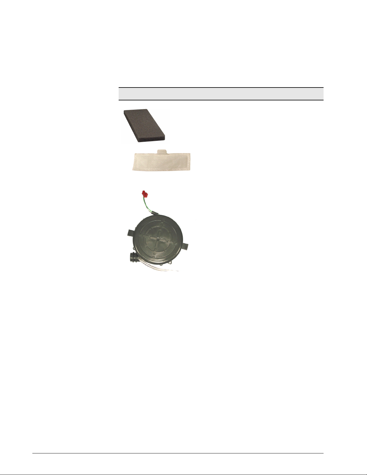
Air Inlet Filter(s) The air inlet filter removes coarse particulate from
Blower The blower draws room air though the air inlet filter and
ambient air as it is entrained into the blower assembly.
See Section 4 for periodic maintenance information.
The BiPAP Focus has a reusable dust filter that is gray in
color. An optional pollen filter, white in color is also
available.
muffler, and outputs air for delivery to the patient. The
DC impeller-type blower recirculates air through the flow
valve when not delivering gas to the patient. Compressor
speed is determined by patient settings. The controller
PCB controls compressor speed.
Table 3-1: Air Delivery System Components
3-2 BiPAP® Focus™ Ventilator Service Manual © Respironics, Inc. REF 1029568 Rev A
Page 17
Chapter 3
Theory of Operation
Air Delivery System Components (Continued)
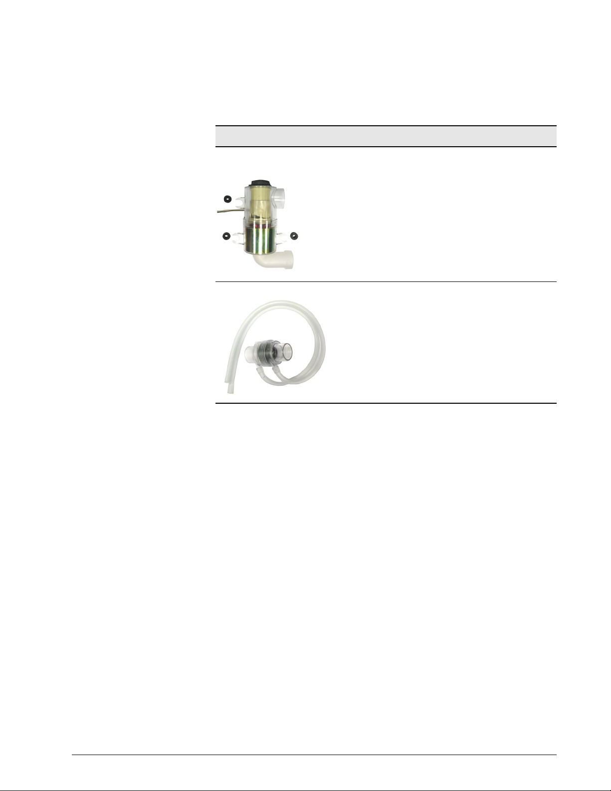
Flow valve (FV) The flow valve (valve assembly) is a mechanical sliding
assembly driven by an electromagnetic coil. Valve
commands from the PCB control current (-125mA to
675mA) to the coil. Movement of the flow valve is
proportional to the current through the coil. The flow
valve operates as a closed-loop system, using feedback
from the flow sensor and pressure transducers.
Air Flow Sensor The air flow sensor measures flow from the flow valve.
The ventilator uses this measurement to provide closed
loop control of the flow valve and to compute the flow
and volume delivered to the patient.
Table 3-1: Air Delivery System Components
REF 1029568 Rev A BiPAP® Focus™ Ventilator Service Manual © Respironics, Inc. 3-3
Page 18
Chapter 3
Theory of Operation
Electronic System Components
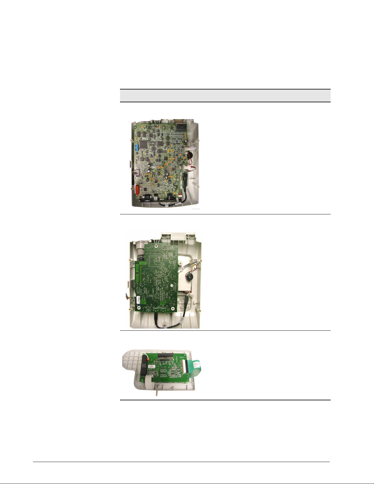
User Interface PCB • Motorola 68332 microcontroller
• Inter-processor communication with controller PCB
• VGA Display, Keyboard and front panel LED Interface
• Primary alarm driver
• Remote alarm relay
• USB and RS-232 serial communication
• Internal Battery charging and monitoring
• Temperature monitor
• Microcontroller watchdog and reset logic
• Voltage monitoring
Controller PCB • Blower On / Off / Closed-Loop Speed Control
• Air Flow Valve Controller
• Pressure Measurement
• RS-232 Communication
• Inter-processor communication with interface PCB
• Backup alarm driver
VGA PCB • STN Blue Mode Transmissive Viewing
• One-Quarter VGA (320 x 240)
• Dot Pitch 0.36mm x 0.36mm
Table 3-2: Electronic System Components
3-4 BiPAP® Focus™ Ventilator Service Manual © Respironics, Inc. REF 1029568 Rev A
Page 19
Theory of Operation
Electronic System Components (Continued)
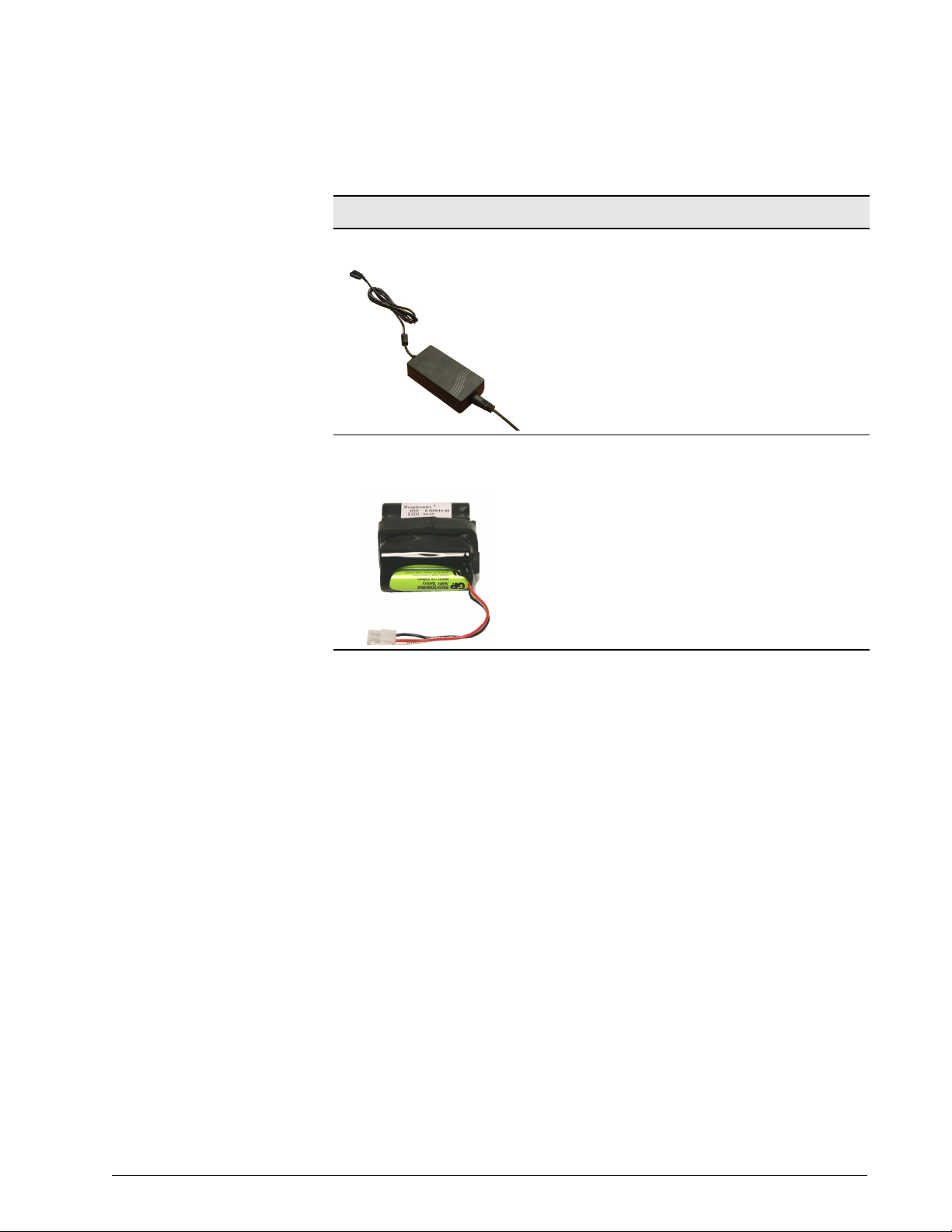
External AC/DC Power Supply • 90-240 VAC, 40-60Hz Input
• 120 Watt 18 Volt DC Output
Chapter 3
Internal NiMH (Nickel Metal Hydride)
Battery
Table 3-2: Electronic System Components
• 8 cell 3.8 Amp Hour provides 9.6 Volt output
nominal
• In-line thermal fuse
• Built-in thermistor for temperature monitoring
• Nominal charge time under 5 hours
• Nominal run time 45 minutes
REF 1029568 Rev A BiPAP® Focus™ Ventilator Service Manual © Respironics, Inc. 3-5
Page 20
Chapter 3
Theory of Operation
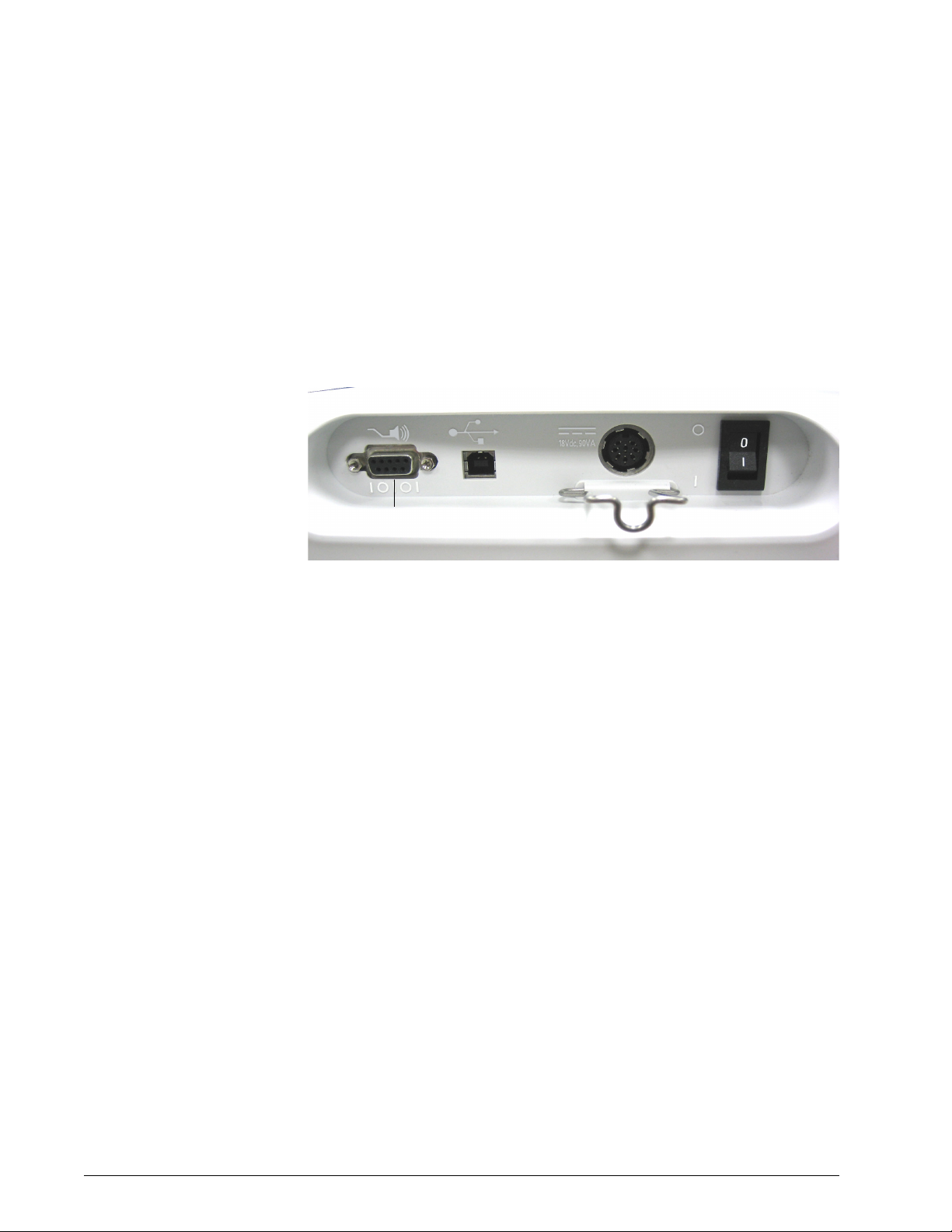
Back Panel The back panel has three connection points and the On/Off switch.
• Nurse call station / serial communications port
•USB port
• AC/DC Power supply input & power cord relief clip
•ON/OFF switch
USB
port
AC/DC power
supply input
ON/OFF switch
Shown in the
OFF position
Nurse call station/serial
communications port
Specifications Default Settings
S/T mode RR = 4/min
IPAP = 12 cmH
EPAP = 4 cmH
Rise-Time = 2 Ramp Start = 4 cmH
Settings: CPAP Mode
CPAP
Continuous Positive Airway
Pressure
Power cord relief clip
Figure 3-1: Back Panel
O I-Time = 1 sec
2
O Ramp Time = 0 min
2
Range: 4-20 cmH
Resolution: 1 cmH
Dynamic accuracy: ±5 cmH
O (4-20 hPa)
2
O (1 hPa)
2
O
2
O (5 hPa)
2
Ramp Time
Period over which the ventilator
increases inspiratory pressure
from Ramp Start setting to
CPAP setting.
Range: 0-45 min.
Resolution: 5 min.
Accuracy: ±10% of setting
3-6 BiPAP® Focus™ Ventilator Service Manual © Respironics, Inc. REF 1029568 Rev A
Page 21

Chapter 3
Theory of Operation
Ramp Start
Initial inspiratory pressure
Settings: S/T Mode
IPAP
Inspiratory positive airway
pressure, the inspiration
pressure setting
EPAP
Expiratory positive airway
pressure, the exhalation
pressure setting
Rise-Time
How quickly the ventilator
increases inspiratory pressure
from EPAP pressure to 67% of
pressure support level
Range: 4 cmH2O to CPAP setting (4 hPa to
CPAP setting)
Resolution: 1 cmH2O (1 hPa)
Range: 4-30 cmH
Resolution: 1 cmH
O (4-30 hPa)
2
O (1 hPa)
2
Dynamic accuracy: ±5 cmH2O (5 hPa)
IPAP cannot be set below EPAP.
Range: 4-25 cmH
O (4-25 hPa)
2
Resolution: 1 cmH2O (1 hPa)
Dynamic accuracy: ±5 cmH
O (5 hPa)
2
Range: 1-6 (where 1 = 0.1 sec and 6 = 0.6 sec)
Resolution: 1
Accuracy: ± (0.15 + 10% of setting) sec
Rate
Respiratory rate, used to
determine if a timed breath is
delivered
Range: 1-30/min
Resolution: 1/min
Accuracy: ±1/min or ±10% of setting, whichever
is greater over a 4-minute period.
I-Time and Rate settings cannot allow I-Time to
exceed expiratory time.
I-Time
Inspiratory time
Range: 0.5-3 sec
Resolution: 0.1 sec
Accuracy: ± (0.1 + 10% of setting) sec
I-Time and Rate settings cannot allow I-Time to
exceed expiratory time.
Ramp Time Range: 0-45 min
Resolution: 5 min
Accuracy: ±10% of setting
Ramp Start
Initial inspiratory pressure
Range: 4 cmH
2
Resolution: 1 cmH
O to EPAP (4 hPa to EPAP)
O (1 hPa)
2
REF 1029568 Rev A BiPAP® Focus™ Ventilator Service Manual © Respironics, Inc. 3-7
Page 22

Chapter 3
Theory of Operation
Measured Data
Patient circuit pressure bar
graph (continuous display)
Rate
Measured respiratory rate
Est. Vt
Estimated delivered tidal
volume
Est. MV
Estimated exhaled minute
volume
Range: 0-35 cmH2O (0-35 hPa)
Resolution: 1 cmH
Accuracy: ±10% of scale
In the event of total loss of power, the inspiratory
and expiratory pressure measured at the patient
exhalation port at 60 L/min is less than 1 cmH2O
by virtue of mask and ventilator design.
Range: 0-60/min
Resolution: 1/min
Accuracy: ± (1 + 10% reading)
Range: 0-4000 mL
Resolution: 1 mL
Accuracy (S/T Mode): ± (50 mL + 10% reading)
(when leak <60 L/min, using the Vision circuit)
Accuracy (CPAP Mode): ± (100 mL + 10%
reading) (when leak <60 L/min, using the Vision
circuit)
Vt display flashes when peak inspiratory flow for
successive breaths varies by more than 15 L/
min.
Range: 0-99 L/min
Resolution: 0.1 L/min
Accuracy: ± 1 L or ± 10% actual, whichever is
greater (when leak is <60 L/min using the Vision
circuit).
O (1hPa)
2
Leak
Estimated Patient leak
#Apnea
Brief apnea periods
Trigger
Breath trigger
NOTE: Est. Vt and Est. MV estimates are at ambient temperature and pressure, dry
(ATPD). Pressure signals are filtered using a 50-Hz low pass Butterworth filter.
Range: 0-150 L/min
Resolution: 1 L/min
Accuracy: ± (15 L/min +10%)
Range: 0-99/hour
Resolution: 1/hour
Accuracy: ± 1/hour (after 1 hour)
Range: Patient or Timed (ventilator)
3-8 BiPAP® Focus™ Ventilator Service Manual © Respironics, Inc. REF 1029568 Rev A
Page 23

Alarm Settings
Chapter 3
Theory of Operation
Apnea
The length of time without a
spontaneous breath that triggers the
Apnea alarm
#Apnea
The number of periods (10-seconds or
more) in the previous hour where the
patient has not initiated a
spontaneous breath.
NOTE: For the first hour, this value is
an estimate only.
Options
Display Units
Unit of pressure: centimeters of water
(cmH
O), hectoPascals (hPa), or
2
millibars (mbar).
Alarm Volume
Audible alarm volume
Range: 20, 40, 60 sec or OFF
Default setting: 20 sec
Range: 5, 10, 20, or OFF
Default setting: OFF
Range: cmH
Range: OFF, or minimum volume, to
maximum volume, in 5 discrete
settings.
O, hPa, or mbar
2
Contrast
Screen contrast
Brightness
Screen brightness
Reverse Video
Toggles reverse video
Screen Lock Timer Range: ON or OFF
Range: 20% to 100%
Range: 10% to 100%
Range: ON or OFF
REF 1029568 Rev A BiPAP® Focus™ Ventilator Service Manual © Respironics, Inc. 3-9
Page 24

Chapter 3
Theory of Operation
Nurse Call Station/Serial Communications Connector Pinout
Pin Signal
Nurse Call Station
1 Nurse call station common
6 Normally open (NO) during normal (non-alarm) operation
9 Normally closed (NC) during normal (non-alarm) operation
Serial Communications
2 Respironics advanced serial protocol (RASP) RS-232 Transmit (Tx)
3 RASP RS-232 Receive (Rx)
4 Not used
5 RS-232 signal ground
7 RS-232 Tx (reserved for future use)
8 RS-232 Rx (reserved for future use)
NOTE:
• When pins 1 and 6 are used, the relay is open during normal operation,
and closed during an alarm condition including loss of power.
• When pins 1 and 9 are used, the relay is closed during normal operation,
and open during an alarm condition including loss of power.
• Female DB9 connector pin configuration:
WARNING: Use only Respironics-supplied cables with the nurse call station/serial
communications connector.
Physical
BiPAP Focus
System Dimensions
355-mm H x 290-mm W x 140-mm D (14.0-in. H x 11.4-in.
W x 5.5-in. D)
Excluding accessories, gas inlets, patient connections.
Weight 4.5 kg (10 lbs.)
3-10 BiPAP® Focus™ Ventilator Service Manual © Respironics, Inc. REF 1029568 Rev A
Page 25

Chapter 3
Theory of Operation
Power
Input range 90-264 V~, 47-63 Hz, 90 VA
Battery backup 3.8 amp-hour (Ah) nickel metal hydride (NiMH) battery
provides 45 minutes of operation at default settings.
System automatically activates the battery charge cycle
when connected to AC power and the ON/OFF switch is
ON ( | ) (during normal operation or Standby mode).
Recharge time is typically under 5 hours, but may extend
further depending on machine settings if operating on
battery prior to recharge, or if operating in elevated
ambient temperature (above 28°C). Charge is complete
when the green CHARGING LED extinguishes.
Nurse call station relay Rated current: 0.280 A
Rated voltage: 250V
Fuse type No replaceable fuses.
Power cord Refer to the“Complete Parts List” on page 9-1
Triggers and Cycles
Volume-based trigger
Flow reversal cycle
Shape signal
Timed trigger
IPAP maximum of 3.0 seconds
Peak flow cycle
Supplemental Oxygen
Flow and pressure into
oxygen valve
Maximum flow: 15 L/min at ambient pressure
Environmental
Temperature Operating: +5 to +35°C at 10 to 95% relative
humidity
Storage: -20 to 60°C at 95% relative humidity
Atmospheric pressure Operating: 83 to 102 kPa (830 to 1020 mBar)
REF 1029568 Rev A BiPAP® Focus™ Ventilator Service Manual © Respironics, Inc. 3-11
Page 26

Chapter 3
Theory of Operation
Storage When the BiPAP Focus is not in use for periods
of 2 weeks or longer, it is recommended that the
unit be stored in a clean, sanitized plastic bag.
Bacteria Filter
Dead space 68 mL
Bacteria/viral filter
efficiency
Resistance 0.7 cmH
Connectors Male connector 15-mm I.D./22-mm O.D.
>99.99%
P/N 342077
O/L/s at 0.5 L/s
2
Female connector 22-mm I.D.
Date of Manufacture
The 12-digit serial number located on the base of the unit indicates the date of
manufacture. From left to right, the fifth and sixth digits indicate the year; the
seventh and eighth, the month; the ninth and tenth, the day. For example, the
serial number 0001050903-20 indicates that the device was manufactured 3
September, 2005.
3-12 BiPAP® Focus™ Ventilator Service Manual © Respironics, Inc. REF 1029568 Rev A
Page 27
Pneumatics BiPAP Focus System pneumatic diagram:
Chapter 3
Theory of Operation
Air inlet
port
BiPAP Focus System
Air inlet
filter
Muffler
Blower
(motor)
Pressure sensor
Flow sensor
Control
valve
Tubing (elbow)
Diffuser
Bacteria filter
(mandatory)
Patient circuit
(to mask outlet)
Oxygen adapter
(if using oxygen)
Oxygen valve
(if using oxygen)
Outlet port and
pressure sensor
REF 1029568 Rev A BiPAP® Focus™ Ventilator Service Manual © Respironics, Inc. 3-13
Page 28

Chapter 3
Theory of Operation
(This page is intentionally blank.)
3-14 BiPAP® Focus™ Ventilator Service Manual © Respironics, Inc. REF 1029568 Rev A
Page 29

Chapter 4. Periodic Maintenance
This chapter provides guidelines and illustrates the cleaning and maintenance
procedures for the BiPAP Focus system.
Table summarizes maintenance procedures for the BiPAP Focus System.
To ensure correct operation, perform all maintenance at the recommended
intervals.
BiPAP Focus System Maintenance
Part Interval Procedure
Battery Replace the battery if a
Batt. Charge Failure alarm
occurs, or as indicated in
See “Replacing the
Battery” on page 4-3.
Air inlet filter(s) Reusable: clean monthly
or as needed.
Reusable: every year or as
needed.
Disposable: replace as
needed.
The air path cannot be
cleaned.
System exterior As needed. Clean the exterior of the ventilator with
Qualified service technician only.
NOTE: If the unit has been in
storage or has not been used for 3
months, the battery will require a
full charge.
Follow the “Cleaning the Reusable Air
Inlet Filter” on page 4-2.
Replace.
Do not attempt to clean or reuse
disposable filters.
a soft damp cloth moistened with any
of the following solutions:
• Mild detergent or soapy water
• 10% bleach solution (90% water)
• Isopropyl alcohol (91%)
• Quaternary ammonium germicides
(sprays or disposable cloths)
Do not spray or immerse in liquid. Do
not allow liquid to penetrate the
system.
Flow Valve
Assembly
10,000 hours
(Total operating hours
Refer to Figure 5-3 on
page 5-3.)
Replace Flow Valve Assembly
Table 4-1: BiPAP Focus System Maintenance
REF 1029568 Rev A BiPAP® Focus™ Ventilator Service Manual © Respironics, Inc. 4-1
Page 30

Chapter 4
Periodic Maintenance
Storing the BiPAP
Focus
Cleaning the
Reusable Air Inlet
Filter
When the BiPAP Focus is not in use for periods of 2 weeks or longer, it is
recommended that the unit be stored in a clean, sanitized plastic bag.
While the unit is being stored, ensure that the power switch on the back of the
unit is in the OFF (O) position. If the switch is not turned OFF, the internal
battery will be depleted within two weeks. If the unit is stored with the power
switch in the OFF (O) position, the internal battery will deplete within 3
months.
Follow these steps to clean the reusable air inlet filter (Figure 1):
1. Remove the filter via the main rear access door (filter door) and
examine for damage or debris on the filter.
2. Wash using one of the following solutions, then rinse thoroughly:
• Liquid dishwashing detergent
• White distilled vinegar (5% acidicy)
• Isopropyl alcohol (99.9%)
• Hydrogen peroxide (3%)
• Bleach
• Sodium hypochloride (6%)
3. Allow the filter to dry completely before reinstalling.
Figure 1: Reusable Air Filter
Reusable
air inlet filter
(gray)
CAUTION: Failure to replace a dirty filter may cause the device to operate at higher
than normal temperatures and damage the device.
CAUTION: Use only Respironics-approved filters.
CAUTION: The gray reusable air inlet filter must be completely dry before use. Never
place a wet filter into the device.
Filter door
4-2 BiPAP® Focus™ Ventilator Service Manual © Respironics, Inc. REF 1029568 Rev A
Page 31

Chapter 4
Periodic Maintenance
Replacing the Air
Inlet Filter(s)
The reusable air inlet filter (gray) must be installed and replaced every year.
An additional ultra-fine disposable filter (white) is also recommended for
enhanced particulate filtering.
CAUTION: Replace any filter that is damaged.
CAUTION: Do not attempt to clean or reuse disposable air inlet filters.
CAUTION: Do not place more than one gray reusable air inlet filters that come with
the ventilator into the device at the same time. One gray reusable air inlet
filter and one white disposable ultra-fine filter may be used.
Replacing the Battery WARNING: To avoid the risk of fire, use only Respironics-approved batteries. All battery
connections are keyed to ensure proper connection. Do not attempt to connect
a battery incorrectly. Only qualified technicians should install the battery.
NOTE: NOTE: If a Low Battery or Battery Depleted alarm occurs during Pre-
Operational Check, then the battery requires charging. If a Batt. Charge
Failure alarm occurs, the battery may be fully depleted. A re-charge is
recommended before proceeding. If the battery does not begin to charge
after one hour and the Batt. Charge Failure persists, contact customer
service for a replacement battery.
NOTE: Battery alarms will sound towards the end of the battery test. Gas delivery
will continue during this time, until the battery is depleted.
If the number of battery powered operations is greater than 220 per year, the
battery should be replaced every six months. If the number of battery
powered operations is less than 220 per year, the battery should be replaced
every year. It is recommended that the battery be tested once per month. A
fully charged battery is designed to operate for 45 minutes at default settings
(See “Power” on page 3-11). If the battery does not continue to deliver gas for
45 minutes at these settings, it should be replaced.
REF 1029568 Rev A BiPAP® Focus™ Ventilator Service Manual © Respironics, Inc. 4-3
Page 32

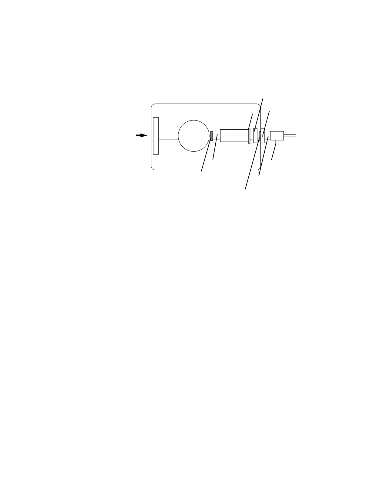
Chapter 4
Periodic Maintenance
Battery compartment
Battery cable
connector
Figure 4-1: Replacing the Battery
Follow these steps:
1. Turn the system OFF and disconnect the DC power supply.
2. Remove the two screws that secure the battery compartment door.
3. Unplug the battery cable and remove the old battery from its
compartment.
4. Insert a new Respironics-approved battery (see “BiPAP Focus
Replacement Parts List” on page 9-1) into the compartment and plug
the battery cable into its connector.
5. Replace the battery compartment door and screws.
6. Reconnect the DC power supply.
CAUTION: Use only Respironics-approved batteries.
4-4 BiPAP® Focus™ Ventilator Service Manual © Respironics, Inc. REF 1029568 Rev A
Page 33

Chapter 5. Diagnostic Mode and
Troubleshooting
This section describes the BiPAP Focus diagnostic mode and other
troubleshooting procedures.
Diagnostic mode allows:
• View product information, including serial numbers and versions of
software and hardware.
• View and adjust system settings, including Language, time since last
service, date and time.
• View and adjust operator preferences, including units of pressure,
alarm volume, contrast, brightness, reverse video and screen lock.
• View the significant event log.
• View the UI board controls and sensor readings for troubleshooting.
• Test alarm indicators and view internal voltages for troubleshooting.
• Test blower and controller board backup alarm.
Entering Diagnostic
Mode
WARNING: Diagnostic mode suspends normal ventilation: disconnect the patient from
the ventilator before entering diagnostic mode.
CAUTION: Troubleshooting and repair should be performed only by a qualified
service technician.
To enter diagnostic mode, simultaneously press the Alarm/Reset and Alarm/
Silence keys on the ventilator front panel at power up for 15 seconds or until
diagnostic mode appears on the screen. At the warning prompt, press Enter to
start diagnostic mode. The diagnostic main menu (Figure 5-1) appears.
REF 1029568 Rev A BiPAP® Focus™ Ventilator Service Manual © Respironics, Inc. 5-1
Page 34

Chapter 5
Diagnostic Mode and Troubleshooting
Figure 5-1: Diagnostic Mode Main Menu
Press the arrow keys to highlight the menu selection, then press Enter.
To exit diagnostic mode at any time, turn the ventilator off.
Product Information The product information screen (Figure 5-2) displays serial number and
version number information for hardware and software components of the
ventilator.
To view the product information screen, use the arrow keys to highlight
PRODUCT INFORMATION on the diagnostic mode main menu, then
press Enter. Press Menu to return to the main menu.
Figure 5-2: Diagnostic Mode: Product Information Screen
5-2 BiPAP® Focus™ Ventilator Service Manual © Respironics, Inc. REF 1029568 Rev A
Page 35

Diagnostic Mode and Troubleshooting
System Settings The systems settings screen (Figure 5-3) allows:
• Set the date and time: select the month, day, year, hour, minute, and
12- or 24-hour format.
• Language, Time Since Service: choose the Language and reset the
time since the last service
1. Use the arrow keys to highlight the field or button whose value to
change, then press Enter.
2. Use the arrow keys to adjust a value or select a setting from a drop-
down menu, then press Enter (or press Cancel to exit without making a
change).
3. Press the Menu key to return to the main menu.
Chapter 5
Figure 5-3: Diagnostic Mode: System Settings Screen
Preferences The preferences screen (Figure 5-13) allows:
• Adjust display units.
• Adjust alarm volume.
• Adjust display contrast.
• Adjust display brightness.
• Select reverse or normal video.
• Adjust screen lock timer.
REF 1029568 Rev A BiPAP® Focus™ Ventilator Service Manual © Respironics, Inc. 5-3
Page 36

Chapter 5
Diagnostic Mode and Troubleshooting
Figure 5-4: Diagnostic Mode: Preferences Screen
To view the preferences screen, use the arrow keys to highlight PREFERENCES
on the diagnostic mode main menu, then press Enter.
1. Use the arrow keys to highlight the button whose value to change, then
press Enter:
2. If selected:
Display Units, the screen shows the current ventilator units settings.
Use the arrow keys to highlight cmH
O, hPa, or mbar then press Enter.
2
Alarm Volume, a popup screen displays the current alarm volume
setting. Use the arrow keys to adjust the volume from 1 to 5 (in
increments of 1), then press Enter (or press Cancel to exit without
making a change). The alarm volume cannot be turned completely off.
Contrast, a popup screen displays the current display contrast setting.
Use the arrow keys to adjust the contrast from 20% to 100% (in
increments of 20%), then press Enter (or press Cancel to exit without
making a change).
Brightness, a popup screen displays the current display brightness
setting. Use the arrow keys to adjust the contrast from 10% to 100%
(in increments of 10%), then press Enter (or press Cancel to exit
without making a change).
Reverse Video, pressing Enter toggles between reverse and normal
video.
Screen Lock Timer, the screen displays on/off lock setting. Use the
arrow keys to select, the press Enter.
3. Press the Menu key to return to the main menu.
5-4 BiPAP® Focus™ Ventilator Service Manual © Respironics, Inc. REF 1029568 Rev A
Page 37

Chapter 5
Diagnostic Mode and Troubleshooting
Significant Event Log The significant event log (Figure 5-5) allows viewing a log of system events,
including settings changes, alarms, and codes that can be used for
troubleshooting. See “Significant Event Log” on page 5.which describes
significant event codes in detail. The log includes the 200 most recent events.
Setting Up the Serial
Interface for DRPT
Figure 5-5: Diagnostic Mode: Significant Event Log
To view the significant event log, use the arrow keys to highlight SIGNIFICANT
EVENT LOG on the diagnostic mode main menu, use the arrow keys to scroll
up and down. Press Menu to return to the main menu.
Follow these steps to connect the ventilator and a PC to create a diagnostic
report (DRPT):
1. Connect BiPAP Focus Communications Cable (P/N 1030010)
between the PC and BiPAP Focus ventilator. Connect the male end
labeled Diagnostics to the back of the ventilator and the female end to
the service PC.
2. Power up the ventilator in diagnostic mode: simultaneously press the
Alarm/Reset and Alarm Silence keys for approximately 15 seconds
while turning ventilator power on.
3. Launch the HyperTerminal program on the PC by clicking Start >
Programs > Accessories > Communications > HyperTerminal, then
double-clicking on the HyperTerminal icon.
4. Enter a name for the connection (BiPAP Focus Communications is
entered in Figure 5-6) and choose an icon, then click OK).
REF 1029568 Rev A BiPAP® Focus™ Ventilator Service Manual © Respironics, Inc. 5-5
Page 38

Chapter 5
Diagnostic Mode and Troubleshooting
Figure 5-6: Entering a Name for the Connection to the BiPAP Focus Ventilator
5. Select the appropriate serial port (Figure 5-7 shows Com1 selected),
then click OK.
Figure 5-7: Selecting the Serial Port
6. Enter these settings for the serial port (Figure 5-8):
Figure 5-8: Serial Port Settings
5-6 BiPAP® Focus™ Ventilator Service Manual © Respironics, Inc. REF 1029568 Rev A
Page 39

Chapter 5
Diagnostic Mode and Troubleshooting
7. Click OK.
8. The blank HyperTerminal window remains. Continue configuring the
properties. Click File > Properties from the menu bar.
9. Click on the Settings tab (Figure 5-9).
10. Select ANSIW from the Emulation drop-down list box.
Figure 5-9: HyperTerminal Settings Tab
11. Click the Terminal Setup button.
12. Select underline and blink for cursor settings then click OK.
Figure 5-10: Terminal Settings
13. Click the ASCII Setup button (Figure 5-9).
REF 1029568 Rev A BiPAP® Focus™ Ventilator Service Manual © Respironics, Inc. 5-7
Page 40

Chapter 5
Diagnostic Mode and Troubleshooting
14. Match the ASCII Setup screen (Figure 5-11), then click OK.
Figure 5-11: ASCII Setup Screen
15. Save this configuration. Select File > Save As and save to the desktop
if you want to create an icon for BiPAP Focus Communications on the
Windows desktop.
5-8 BiPAP® Focus™ Ventilator Service Manual © Respironics, Inc. REF 1029568 Rev A
Page 41

Chapter 5
Diagnostic Mode and Troubleshooting
Generating a
Diagnostic Report
(DRPT)
1. With the BiPAP Focus ventilator in diagnostic mode and the serial
communcations cable, the end labeled Diagnostics connected to the
ventilator, start HyperTerminal, open the BiPAP Focus
Communications file, or click on the BiPAP Focus Communications
icon on the PC (if created).
2. Type DRPT (all caps) in the dialog box, and press the Enter key. This
pulls information found in the significant event log.
3. If the ventilator is connected and communication occurs, a response
similar to the following appears:
Respironics Inc. BiPAP Focus Ventilator
Serial Number: 8772060206-04
Date & Time : 6/19/06 20:49
Event ID Date Time
905 Pwr O n r e set 6/1 9 / 0 6 20:43
300 POS T S u c ce ssful 6/1 9 / 0 6 20:43
102 Pow e r O f f 6/1 9 / 0 6 20:42
4 3 7 B a t t e r y V o l t a g e F a i l e d 6 / 1 9 / 0 6 2 0 : 4 2 V 6 1 5 , 6 1 5
639 Dis c o n n e ct 6/1 9 / 0 6 20:42
6 3 5 B a t t e r y D e p l e t e d 6 / 1 9 / 0 6 2 0 : 4 2 6 3 7 , 6 3 3
644 Apne a 6/19/06 20 : 4 2
639 Disconnect 6/19/06 20:
6 3 5 B a t t e r y D e p l e t e d 6 / 1 9 / 0 6 2 0 : 4 1 6 8 7 , 6 4 9
6 4 3 L o w B a t t e r y 6 / 1 9 / 0 6 2 0 : 4 1 7 1 4 , 7 2 3
905 Pwr O n r e set 6/1 9 / 0 6 20:41
300 POS T S u c ce ssful 6/1 9 / 0 6 20:41
102 Pow e r O f f 6/1 9 / 0 6 20:41
905 Pwr O n r e set 6/1 9 / 0 6 20:26
300 POS T S u c ce ssful 6/1 9 / 0 6 20:26
102 Pow e r O f f 6/1 4 / 0 6 16:52
905 Pwr O n r e set 6/1 3 / 0 6 16:32
300 POS T S u c ce ssful 6/1 3 / 0 6 16:32
102 Pow e r O f f 6/1 3 / 0 6 16:32
639 Dis c o n n e ct 6/1 3 / 0 6 16:31
905 Pwr O n r e set 6/1 3 / 0 6 16:27
300 POST Successful 6/13/06 16:27
REF 1029568 Rev A BiPAP® Focus™ Ventilator Service Manual © Respironics, Inc. 5-9
Page 42

Chapter 5
Diagnostic Mode and Troubleshooting
Figure 5-12 shows how to interpret each line of the DRPT report.
437 Battery Voltage Failed 6/19/06 20:42 V 615,615
615, 615 - Actual
measurement value
(A/D counts)
V or T - System errors
V= voltage, T= temperature
20:42 - Time stamp of most recent
diagnostic mode occurrence
6/19/06 - Date stamp of most recent
diagnostic code occurrence
Battery Voltage Failed - description
437 - Diagnostic Code
Figure 5-12: Interpreting the DRPT Report
5-10 BiPAP® Focus™ Ventilator Service Manual © Respironics, Inc. REF 1029568 Rev A
Page 43

Diagnostic Mode and Troubleshooting
Sensor Readings The sensor readings screen (Figure 5-13) allows:
View sensor readings: view these readings to see the real-time effect of
changes to voltages, temperature and control signals.
Chapter 5
Figure 5-13: Diagnostic Mode: Sensors Screen
Table 5-1 defines sensor readings for the BiPAP Focus.
NOTE: Hi = 1 and Lo = 0
Sensor Readings Defined
Diagnostics Label Actual Measured Value Description
+3.3V +3.3V_MEAS Measurement of +3.3V
Supply count limits: 883 to 976
Voltage (V) = counts * 0.003662
+5V +5V_MEAS Measurement of +5V
Supply count limits: 884 to 977
Voltage (V) = counts * 0.005371
+12V +12V_MEAS Measurement of +12V supply
Count limits: 889 to 983
Voltage(V) = counts * 0.012817
Table 5-1: Sensor Readings Defined (Sheet 1 of 4)
REF 1029568 Rev A BiPAP® Focus™ Ventilator Service Manual © Respironics, Inc. 5-11
Page 44

Chapter 5
Diagnostic Mode and Troubleshooting
Diagnostics Label Actual Measured Value Description
+18Vin 18VIN_MEAS Measurement of +18V (mains input)
+18V Boost 18V_BOOST_MEAS Measurement of +18V_Boost supply
VBATT/VTEMP VBATT_VTEMP_MEAS Battery Temperature measurement when
Sensor Readings Defined
Count limits: 882 to 1008
Voltage(V) = counts * 0.019043
Count limits: 923 to 1020
Voltage(V) = counts * 0.019043
unit operating from Mains or Battery
Voltage measurement when operating on
battery.
Counts limit (volt.): 624 to 936
Voltage(V) = counts * 0.012817
Counts limit (temp.): 79 to 421
Within limits - battery temp ok.
VOptoCap OPTO_CAP_MEAS Measurement of backup capacitor voltage
on User Interface Board.
Count limits: 616 to 782
Voltage(V) = counts * 0.005371
Board Temp BOARD_TEMP_MEAS Measurement of temperature on the User
Interface PCB
Count limits: 233 to 540
Temp. (degC) = ((counts * .00244) - 0.6) *
100
Ambient Temp TEMP_DATA Measurement of Ambient Temperature
within the unit
Limits : 0 to 60degC.
+18VINCMP VIN_COMP_BUF Signal for detection if the incoming mains
voltage is above a certain threshold
(15.64V typically).
Hi: Above threshold
Lo: Below threshold
Table 5-1: Sensor Readings Defined (Sheet 2 of 4)
5-12 BiPAP® Focus™ Ventilator Service Manual © Respironics, Inc. REF 1029568 Rev A
Page 45

Chapter 5
Diagnostic Mode and Troubleshooting
Sensor Readings Defined
Diagnostics Label Actual Measured Value Description
+18VBSTCMP 18V_BOOST_COMP Signal for detection if the 18V_Boost mains
voltage is above a certain threshold
(15.64V typically)
Hi: Above threshold
Lo: Below threshold
BattChrgFault BATT_CHRG_FAULT_BUF Signal for detection if there is a fault in the
battery charging
Hi: Fault
Lo: No Fault
BattOnChrg BATT_ON_CHG_BUF Signal for detection if the battery is being
charged
Hi: Battery charging
Lo: Battery not charging
BattChrgToc BATT_CHR_TOC Signal for detection if a top-off charge is
being applied to battery
Hi: Battery NOT in TOC state
Lo: Battery in TOC state
BattChrgRdy BATT_CHG_READY_BUF Signal for detection if the battery is ready
PORLATCH EXT_WDOG_LATCHED Signal for detection if the processor was
for charging
Hi: Ready for charging
Lo: Not ready for charging
reset due to a drop in the +3.3V rail. This
signal must be primed by software, with the
EXT_WDOG_LATCH_CLR signal. This can
be done using the PORLATCLK diagnostics
label in the System Test screen.
Hi: Loss of +3.3V supply caused last reset
Lo: Last reset not caused by loss of +3.3V
supply. Probably caused by watchdog
(software reset)
Table 5-1: Sensor Readings Defined (Sheet 3 of 4)
REF 1029568 Rev A BiPAP® Focus™ Ventilator Service Manual © Respironics, Inc. 5-13
Page 46

Chapter 5
Diagnostic Mode and Troubleshooting
Diagnostics Label Actual Measured Value Description
PWRSWMON PWR_SW_MON_PROC User interface Standby Key monitor
PWRSWLATCH PWR_SW_LATCHED Latched User interface Standby Key
Sensor Readings Defined
Hi: Standby key is in-active (released).
Lo: Standby key is active (pressed).
monitor. This signal must be primed by
software with the PWR_SW_CLK signal.
This can be done using the PWRSWCLK
diagnostics label in the System Test screen.
Hi: Standby key has NOT been pressed.
Lo: Standby key has been pressed.
Table 5-1: Sensor Readings Defined (Sheet 4 of 4)
5-14 BiPAP® Focus™ Ventilator Service Manual © Respironics, Inc. REF 1029568 Rev A
Page 47

Diagnostic Mode and Troubleshooting
System Test The alarm, indicator, and voltage screen (Figure 5-14) allows:
• Test alarms: toggle the primary alarm speaker, backup alarm speaker,
or remote alarm ON or OFF.
• Indicators: toggle the Alarm LED, Silence LED, and the On Battery
LED, ON or OFF.
• Miscellaneous Tests: toggle the following settings ON or OFF:
Blower, VBattMeasEn, V Out Enable, POWERSWCLK, PWRTUIOFF,
PORLATCLK, WDSTROBE.
NOTE: When the V BattMeasEn signal is asserted is enables the measurement
of the Battery Thermistor temperature on the sensor readings screen.
Chapter 5
Figure 5-14: Diagnostic Mode: System Test Screen
System Test Defined
Diagnostics
Label Schematic Label Description
BLOWER TCB_SWITCH_ON
and
TCB_SWITCH_OFF
V BattMeasEn VBATT_MEAS_EN Selects ADC measurement of battery voltage or battery
Table 5-2: System Test Defined (Sheet 1 of 2)
REF 1029568 Rev A BiPAP® Focus™ Ventilator Service Manual © Respironics, Inc. 5-15
Used to turn blower on/off TCB_SWITCH_ON Hi and
TCB_SWITCH_OFF Lo: Blower ON TCB_SWITCH_ON Lo
and TCB_SWITCH_OFF Hi: Blower OFF
These signals are mutually exclusive in software
temperature
Hi: Battery voltage measured by ADC
Lo: Battery temperature measured by ADC
Page 48

Chapter 5
Diagnostic Mode and Troubleshooting
Diagnostics
Label Schematic Label Description
V Out Enable VOUT_EN Option to turn on/off the power out to the TCB.
PWRSWCLK PWR_SW_CLK Clocks the Standby Switch latch.
PWRTUIOFF PWR_TUI_OFF PWR_TUI_OFF: Control line to switch off the power.
PORLATCLK EXT_WDOG_LATC
H_CLR
System Test Defined
Reserved for future use. Therefore, the option to control
the power to the UI cannot be changed in software.
If used, the following applies:
HI: Turns on the 18V_Boost out to the Controller Board.
LO: Turns off the 18V_Boost out to the Controller Board.
Lo to Hi: Clocks a '1' to the latch output.
Hi to Lo: No change of state.
Hi: Clears the latch which removes the 18V_Boost rail
from the system, thereby shutting down power by placing
the unit in Standby mode.
Lo: No change in state
Clocks the Power On Reset latch. This can be used to
determine if an external power on reset has occurred due
to the +3.3V rail dropping.
Significant Event
Codes
Lo to Hi: No change of state.
Hi to Lo: Clocks a '1' to the latch output.
WDSTROBE WDSTROBE WDSTROBE: External watchdog strobe. Software is
required to apply a high pulse of 50ns minimum duration
at a maximum of every 1.2seconds to avoid the watchdog
resetting the processor.
Table 5-2: System Test Defined (Sheet 2 of 2)
The BiPAP Focus Ventilator generates a log of system events, including
settings changes, alarms, and codes that can be used for troubleshooting. If a
ventilator inoperative condition or unexpected reset occurs, the significant
event log includes the ventilator settings, patient data, and alarm conditions
that were in effect.
The significant event log can include at least 200 of the most recent events,
with the most recent events listed first. The ventilator maintains the significant
event log regardless of whether there is power to the ventilator.
The significant event log includes the following information:
1. Event ID: This includes a code and brief text description of the event.
5-16 BiPAP® Focus™ Ventilator Service Manual © Respironics, Inc. REF 1029568 Rev A
Page 49

Chapter 5
Diagnostic Mode and Troubleshooting
2. Date: Each event is date-stamped in a month/day/year format (for
example, 10/20/02).
3. Time : Each event is time-stamped in hour/minute/second format (for
example, 09:15:23).
4. Old value: For settings changes, the previously selected value is
displayed.
5. New value: For settings changes, the most recently selected value is
displayed.
Use the arrow keys to scroll through the log.
NOTE: Table 5-3 lists event IDs, and recommends corrective actions if
appropriate. When performing corrective actions:
• Perform the corrective actions in the order listed (if applicable)
until the problem is resolved.
• Before replacing a part, slave in a replacement part to verify that
it corrects the problem. If so, verify that the problem recurs with
the original part installed, then replace the part and confirm that
the problem is corrected.
Significant Event Log: Event IDs
Code Short text for code Comment / Corrective Action
1 ERR SOFTWARE Controller processor detected a software error.
If this persists and leads to multiple resets and the
system declaring a system error because too many
errors occurred in 24 hours, replace the controller PCB.
2 ERR PROGRAM CRC FAILURE Controller processor detected a program memory
checksum error.
If this persists replace the controller PCB.
3 ERR EXTERNAL RAM
FAI LUR E
4 ERR FIQ STACK OVERFLOW Controller processor detected a stack overflow.
Table 5-3: Significant Event Log: Event IDs (Sheet 1 of 22)
Controller processor detected an external RAM memory
error.
If this persists replace the controller PCB.
If this persists and leads to multiple resets and the
system declaring a system error because too many
errors occurred in 24 hours, replace the controller PCB.
REF 1029568 Rev A BiPAP® Focus™ Ventilator Service Manual © Respironics, Inc. 5-17
Page 50

Chapter 5
Diagnostic Mode and Troubleshooting
Code Short text for code Comment / Corrective Action
5 ERR FIQ STACK UNDERFLOW Controller processor detected a stack underflow.
6 ERR NEST STACK OVERFLOW Controller processor detected a stack overflow.
7 ERR NEST STACK
UNDERFLOW
8 ERR IRQ STACK OVERFLOW Controller processor detected a stack overflow.
9 ERR IRQ STACK UNDERFLOW Controller processor detected a stack underflow.
Significant Event Log: Event IDs (Continued)
If this persists and leads to multiple resets and the
system declaring a system error because too many
errors occurred in 24 hours, replace the controller PCB.
If this persists and leads to multiple resets and the
system declaring a system error because too many
errors occurred in 24 hours, replace the controller PCB.
Controller processor detected a stack underflow.
If this persists and leads to multiple resets and the
system declaring a system error because too many
errors occurred in 24 hours, replace the controller PCB.
If this persists and leads to multiple resets and the
system declaring a system error because too many
errors occurred in 24 hours, replace the controller PCB.
10 ERR TMR STACK OVERFLOW Controller processor detected a stack overflow.
If this persists and leads to multiple resets and the
system declaring a system error because too many
errors occurred in 24 hours, replace the controller PCB.
11 ERR TMR STACK
UNDERFLOW
12 ERR SVC STACK OVERFLOW, Controller processor detected a stack overflow.
13 ERR SVC STACK UNDERFLOW Controller processor detected a stack underflow.
14 ERR THREAD STACK
OVERFLOW
15 ERR ARM UNDEFINED
INSTRUCTION EXCEPTION
Controller processor detected a stack underflow.
If this persists and leads to multiple resets and the
system declaring a system error because too many
errors occurred in 24 hours, replace the controller PCB.
If this persists and leads to multiple resets and the
system declaring a system error because too many
errors occurred in 24 hours, replace the controller PCB.
Controller processor detected a stack overflow.
If this persists and leads to multiple resets and the
system declaring a system error because too many
errors occurred in 24 hours, replace the controller PCB.
Controller processor detected an unexpected exception.
If this persists and to multiple resets and the system
declaring a system error because too many errors
occurred in 24 hours, replace the controller PCB.
Table 5-3: Significant Event Log: Event IDs (Sheet 2 of 22)
5-18 BiPAP® Focus™ Ventilator Service Manual © Respironics, Inc. REF 1029568 Rev A
Page 51

Chapter 5
Diagnostic Mode and Troubleshooting
Significant Event Log: Event IDs (Continued)
Code Short text for code Comment / Corrective Action
16 ERR ARM SWI EXCEPTION Controller processor detected an unexpected exception.
If this persists and leads to multiple resets and the
system declaring a system error because too many
errors occurred in 24 hours, replace the controller PCB.
17 ERR ARM PREFETCH
EXCEPTION
18 ERR ARM ABORT EXCEPTION Controller processor detected an unexpected exception.
20 ERR AIC DEFAULT HANDLER Controller processor detected an unexpected interrupt.
Controller processor detected an unexpected exception.
If this persists and leads to multiple resets and the
system declaring a system error because too many
errors occurred in 24 hours, replace the controller PCB.
If this persists and leads to multiple resets and the
system declaring a system error because too many
errors occurred in 24 hours, replace the controller PCB.
If this persists and leads to multiple resets and the
system declaring a system error because too many
errors occurred in 24 hours, replace the controller PCB.
21 ERR AIC SPURIOUS
HANDLER
22 ERR CAL DATA CRC FAILURE Controller processor detected a calibration data
23 ERR INVALID DRIFT INDEX AT
CAL
24 ERR UNRECOGNIZED CAL
VERSION BY SW
Controller processor detected an unexpected interrupt.
If this persists and leads to multiple resets and the
system declaring a system error because too many
errors occurred in 24 hours, replace the controller PCB.
checksum error.
1. Attempt to re-calibrate the system.
2. If this fails, replace the controller PCB.
Controller processor detected that the flow sensor drift
check has failed. Flow sensor drift and calibration
information can be monitored using the "D) Drift
Screen" from the debug screen using the RASP utility,
capture screen output to a file.
1. Attempt to re-calibrate the system.
2. If this fails, replace the controller PCB.
Controller processor detected that the calibration table
version check has failed.
1. Attempt to re-calibrate the system.
2. If this fails, replace the controller PCB.
Table 5-3: Significant Event Log: Event IDs (Sheet 3 of 22)
REF 1029568 Rev A BiPAP® Focus™ Ventilator Service Manual © Respironics, Inc. 5-19
Page 52

Chapter 5
Diagnostic Mode and Troubleshooting
Code Short text for code Comment / Corrective Action
25 ERR DRIFT FLOW TOO HIGH Controller processor detected that the flow sensor drift
27 ERR DRIFT PRESSURE TOO
HIGH
28 ERR CAL DATA BLANK Controller processor detected that the calibration table
29 ERR DRIFT SECONDARY
PRESSURE TOO HIGH
30 ERR INVALID NVDATA
SCHEMA
31 ERR INVALID NVDATA LOCK Controller processor detected an error accessing the
32 ERR INVALID NVDATA
CHECKSUM
33 ERR NVDATA STORAGE
ERROR
Significant Event Log: Event IDs (Continued)
check has failed.
Flow sensor drift and calibration information can be
monitored using the "D) Drift Screen" from the debug
screen using the RASP utility, capture screen output to
a file.
1. Attempt to re-calibrate the system.
2. If this fails, replace the controller PCB.
Controller processor detected that the drift check on
the primary pressure has failed. Pressure sensor drift
and calibration information can be monitored using
using the "D) Drift Screen" from the debug screen using
the RASP utility, capture screen output to a file.
1. Attempt to re-calibrate the system.
2. If this fails,replace the controller PCB.
is blank.
1. Attempt to re-calibrate the system.
2. If this fails, replace the controller PCB.
Controller processor detected that the drift check on
the secondary pressure has failed.
1. Attempt to re-calibrate the system.
2. If this fails, replace the controller PCB.
Controller processor detected an error in format of the
calibration data in EEPROM.
1. Attempt to re-calibrate the system.
2. If this fails,replace the controller PCB.
calibration data in EEPROM.
1. Attempt to re-calibrate the system.
2. If this fails,replace the controller PCB.
Controller processor detected a checksum error on the
calibration in EEPROM.
1. Attempt to re-calibrate the system.
2. If this fails,replace the controller PCB.
Controller processor detected that the data structure is
bigger than the EEPROM device.
1. Attempt to re-calibrate the system.
2. If this fails,replace the controller PCB.
Table 5-3: Significant Event Log: Event IDs (Sheet 4 of 22)
5-20 BiPAP® Focus™ Ventilator Service Manual © Respironics, Inc. REF 1029568 Rev A
Page 53

Chapter 5
Diagnostic Mode and Troubleshooting
Significant Event Log: Event IDs (Continued)
Code Short text for code Comment / Corrective Action
34 ERR NVDATA QUEUE FULL Controller processor detected that the queue to the
EEPROM manager thread is full.
If this persists and leads to multiple resets and the
system declaring a system error because too many
errors occurred in 24 hours, replace the controller PCB.
35 ERR NVDATA READBACK
FAI LUR E
36 ERR NVDATA RANGE
FAI LUR E
37 ERR CORRUPT RTC VALUE Controller processor detected that the Real Time Clock
Controller processor detected that a write operation to
EEPROM failed the readback check.
If this persists and leads to multiple resets and the
system declaring a system error because too many
errors occurred in 24 hours, replace the controller PCB.
Controller processor detected that a write operation to
EEPROM failed the range check for that data item.
If this persists and leads to multiple resets and the
system declaring a system error because too many
errors occurred in 24 hours, replace the controller PCB.
time and the RTOS tick timer has drifted since it was
last tested. When changing the time, this could happen
and an RTC Failure Alarm maybe annuciated, this
alarm can be reset by pressing Alarm Reset.
No action necessary.
38 ERR RTC NOT TICKING Controller processor detected that the Real Time Clock
39 ERR UI QUEUE FULL Controller processor detected a RTOS queue full
40 ERR INVALID BIST TEST
CALL
time and the RTOS tick timer has drifted significantly
(>4 seconds) since it was last tested. When changing
the time, this could happen and an RTC Failure Alarm
maybe annuciated, this alarm can be reset by pressing
Alarm Reset.
No action necessary.
condition.
If this persists and leads to multiple resets and the
system declaring a system error because too many
errors occurred in 24 hours, replace the controller PCB.
Controller processor detected an invalid BIST test was
attempted to be run.
If this persists and leads to multiple resets and the
system declaring a system error because too many
errors occurred in 24 hours, replace the controller PCB.
Table 5-3: Significant Event Log: Event IDs (Sheet 5 of 22)
REF 1029568 Rev A BiPAP® Focus™ Ventilator Service Manual © Respironics, Inc. 5-21
Page 54

Chapter 5
Diagnostic Mode and Troubleshooting
Code Short text for code Comment / Corrective Action
41 ERR PRESSURE REG OVER Controller processor detected that a high pressure
42 ERR BIST THREAD LOCKED Controller processor detected that the built in selftest
43 ERR ALARM VOLTAGE
FAI LUR E
44 ERR 12VREF FAILURE Controller processor detected that the limits test on the
Significant Event Log: Event IDs (Continued)
condition (i.e. 5 cmH20 above the IPAP or CPAP
setting) lasted for greater than ten seconds.
1. Check for kicked tubes on the Primary pressure
sensor.
2. Check for blockages near the Primary pressure
sensor in the gas outlet port.
3. Replace the controller PCB.
4. If this persists replace the pneumatics subassembly
(blower and valve).
thread is locked, i.e. it's not alive as expected.
If this persists and leads to multiple resets and the
system declaring a system error because too many
errors occurred in 24 hours, replace the controller PCB.
Controller processor detected that the backup alarm
buzzer voltage test failed a limits check for greater than
five seconds.
1. Enter Diagnostics mode and use the System Test
screen, to check if the backup alarm can be turned
on and off.
2. Replace the controller PCB.
12V reference voltage signal failed.
Replace the controller PCB.
45 ERR 5VREF FAILURE Controller processor detected that the limits test on the
46 ERR VBULK FAILURE Controller processor detected that the limits test on the
47 ERR NEG15VREF FAILURE Controller processor detected that the limits test on the
48 ERR FL12 SENSOR RAILED Controller processor detected that the limits test on the
5V reference voltage signal failed.
Replace the controller PCB.
VBULK reference voltage signal failed.
Replace the controller PCB.
-15V reference voltage signal failed.
Replace the controller PCB.
Flow sensor signal failed.
1. Replace the controller PCB.
2. If this persists replace the pneumatics subassembly
(blower and valve)
Table 5-3: Significant Event Log: Event IDs (Sheet 6 of 22)
5-22 BiPAP® Focus™ Ventilator Service Manual © Respironics, Inc. REF 1029568 Rev A
Page 55

Chapter 5
Diagnostic Mode and Troubleshooting
Significant Event Log: Event IDs (Continued)
Code Short text for code Comment / Corrective Action
49 ERR PV2 SENSOR FAILURE Controller processor detected that the limits test on the
secondary pressure sensor signal failed.
1. Replace the controller PCB.
2. If this persists replace the pneumatics subassembly
(blower and valve)
50 ERR FLASH FAILURE Controller processor detected a Boot Flash failure
Replace the controller PCB.
51 ERR UNRECOGNIZED BOARD
REV
52 ERR MOTOR FAILURE Controller processor detected a stalled blower, i.e. less
53 ERR BLOWER RPM FAILED
TOLERANCE
54 ERR BLOWER OFF CURRENT
HIGH
55 ERR PRINTF BUFFER
OVERFLOW
Controller processor detected an out of range board
revision
Replace the controller PCB.
than 1000 RPM.
1. If this persists replace the pneumatics subassembly
(blower and valve).
2. If this persists, replace the controller PCB. The
original pneumatics subassembly (blower and valve)
should be re-inserted and the system retested and
recalibrated
Controller processor detected an out of tolerance
blower speed, i.e. outside +/- 5500 RPM from the
target blower speed for more than 5 seconds.
1. If this persists replace the pneumatics subassembly
(blower and valve).
2. If this persists, replace the controller PCB. The
original pneumatics subassembly (blower and valve)
should be re-inserted and the system retested and
recalibrated
Controller processor detected a current draw of more
than 100mA for more than 5 seconds, when the motor
is powered off.
1. If this persists replace the pneumatics subassembly
(blower and valve).
2. If this persists, replace the controller PCB. The
original pneumatics subassembly (blower and valve)
should be re-inserted and the system retested and
recalibrated
Controller processor detected a buffer overflow while
outputting serial data.
If this persists and leads to multiple resets and the
system declaring a system error because too many
errors occurred in 24 hours, replace the controller PCB.
Table 5-3: Significant Event Log: Event IDs (Sheet 7 of 22)
REF 1029568 Rev A BiPAP® Focus™ Ventilator Service Manual © Respironics, Inc. 5-23
Page 56

Chapter 5
Diagnostic Mode and Troubleshooting
Code Short text for code Comment / Corrective Action
56 ERR BLOWER ON CURRENT
HIGH
57 ERR THERAPY EVENT QUEUE
FULL
59 ERR P1 SENSOR RAILED Controller processor detected that the limits test on the
60 ERR P2 SENSOR RAILED Controller processor detected that the limits test on the
61 ERR RTC BATTERY DEAD Controller processor detected that the Real Time Clock
62 ERR BLOWER RPM
EXCEEDED MAX
63 ERR INTERNAL WATCHDOG
FAI LUR E
Significant Event Log: Event IDs (Continued)
Controller processor detected a current draw of more
than 3000mA for more than 10 seconds, when the
motor is powered on.
1. If this persists replace the pneumatics subassembly
(blower and valve)
2. If this persists, replace the controller PCB.
3. The original pneumatics subassembly (blower and
valve) should be re-inserted and the system retested
and recalibrated
Controller processor detected a RTOS queue full
condition.
If this persists and leads to multiple resets and the
system declaring a system error because too many
errors occurred in 24 hours, replace the controller PCB.
Primary pressure sensor signal failed.
1. Replace the controller PCB.
2. If this persists replace the pneumatics subassembly
(blower and valve)
Secondary pressure sensor signal failed.
1. Replace the controller PCB.
2. If this persists replace the pneumatics subassembly
(blower and valve)
time and the RTOS tick timer has drifted significantly
since it was last tested. When changing the time, this
could happen and an RTC Battery depleted technical
alert maybe annuciated, this can be reset by pressing
Alarm Reset. No action necessary.
Controller processor detected an out of tolerance
blower speed, i.e. above 23337 RPM for more than 3
seconds.
1. If this persists replace the pneumatics subassembly
(blower and valve)
2. If this persists, replace the controller PCB. The
original pneumatics subassembly (blower and valve)
should be re-inserted and the system retested and
recalibrated
Controller processor detected an internal watchdog
failure.
If this persists and leads to multiple resets and the
system declaring a system error because too many
errors occurred in 24 hours, replace the controller PCB.
Table 5-3: Significant Event Log: Event IDs (Sheet 8 of 22)
5-24 BiPAP® Focus™ Ventilator Service Manual © Respironics, Inc. REF 1029568 Rev A
Page 57

Chapter 5
Diagnostic Mode and Troubleshooting
Significant Event Log: Event IDs (Continued)
Code Short text for code Comment / Corrective Action
64 ERR EXTERNAL WATCHDOG
FAI LUR E
65 ERR UNEXPECTED
WATCHDOG
67 ERR RTOS INIT FAILURE Controller processor detected an initialisation failure
Controller processor detected an external watchdog
failure.
If this persists and leads to multiple resets and the
system declaring a system error because too many
errors occurred in 24 hours, replace the controller PCB.
Controller processor detected a watchdog failure, when
it wasn't expecting one.
If this persists and leads to multiple resets and the
system declaring a system error because too many
errors occurred in 24 hours, replace the controller PCB.
when starting the RTOS.
If this persists and leads to multiple resets and the
system declaring a system error because too many
errors occurred in 24 hours, replace the controller PCB.
68 ERR SERIAL QUEUE FULL Controller processor detected a RTOS queue full
condition.
If this persists and leads to multiple resets and the
system declaring a system error because too many
errors occurred in 24 hours, replace the controller PCB.
69 ERR SNORE SAMPLING
THREAD LOCKED
70 ERR MAIN EXECUTION
THREAD LOCKED
71 ERR INTERNAL RAM
FAI LUR E
72 ERR EVENT LOG QUEUE
FULL
Controller processor detected that the snore sampling
thread is locked, i.e. it's not alive as expected.
If this persists and leads to multiple resets and the
system declaring a system error because too many
errors occurred in 24 hours, replace the controller PCB.
Controller processor detected that the main execution
thread is locked, i.e. it's not alive as expected.
If this persists and leads to multiple resets and the
system declaring a system error because too many
errors occurred in 24 hours, replace the controller PCB.
Controller processor detected an internal RAM memory
checksum error.
If this persists and leads to multiple resets and the
system declaring a system error because too many
errors occurred in 24 hours, replace the controller PCB.
Controller processor detected a RTOS queue full
condition.
If this persists and leads to multiple resets and the
system declaring a system error because too many
errors occurred in 24 hours, replace the controller PCB.
Table 5-3: Significant Event Log: Event IDs (Sheet 9 of 22)
REF 1029568 Rev A BiPAP® Focus™ Ventilator Service Manual © Respironics, Inc. 5-25
Page 58

Chapter 5
Diagnostic Mode and Troubleshooting
Code Short text for code Comment / Corrective Action
75 ERR IPC MSG TOO BIG Controller processor detected an IPC message that was
76 ERR ALARM CAPACITOR
FAI LUR E
77 ERR HIGH PRESSURE
REGULATION
Significant Event Log: Event IDs (Continued)
too big.
If this persists and leads to multiple resets and the
system declaring a system error because too many
errors occurred in 24 hours, replace the controller PCB.
Controller processor detected that the backup alarm
buzzer capacitor test failed a limits check for greater
than five minutes.
1. Enter Diagnostics mode and use the System Test
screen, to check if the backup alarm can be turned
on and off.
2. If this persists and leads to multiple resets and the
system declaring a system error because too many
errors occurred in 24 hours, replace the controller
PCB.
Controller processor detected a high pressure condition
and annuciated the "Hi P Reg" alarm. No action
necessary.
If this condition persists for greater than 10 seconds
then the system will declare system error code 41
78 ERR LOW PRESSURE
REGULATION
79 ERR_LOW_PRESSURE_SUPP
ORT_REGULATION
80 ERR IPC QUEUE FULL Controller processor detected a RTOS queue full
81 ERR IPC INVALID MSGID Controller processor detected an IPC message with an
Controller processor detected a low pressure condition
and annuciated the "Lo P Reg" alarm. No action
necessary.
Unable to maintain Pressure Support. System Error
declared after condition is present for one minute.
condition.
If this persists and leads to multiple resets and the
system declaring a system error because too many
errors occurred in 24 hours, replace the controller PCB.
invalid message id.
If this persists and leads to multiple resets and the
system declaring a system error because too many
errors occurred in 24 hours, replace the controller PCB.
Table 5-3: Significant Event Log: Event IDs (Sheet 10 of 22)
5-26 BiPAP® Focus™ Ventilator Service Manual © Respironics, Inc. REF 1029568 Rev A
Page 59

Chapter 5
Diagnostic Mode and Troubleshooting
Significant Event Log: Event IDs (Continued)
Code Short text for code Comment / Corrective Action
82 ERR IPC COMMS FAILURE Controller processor detected an IPC message failure, it
can be due to : a low level I2C receive error, a low level
I2C transmit error or that the once a second I'm alive
message was not received
1. Check the UI PCB to Controller PCB IPC 8-way
multi-coloured cable.
2. If this persists and leads to multiple resets and the
system declaring a system error because too many
errors occurred in 24 hours, replace the controller
PCB.
83 ERR IPC CKSUM FAILURE Controller processor detected an IPC message with an
invalid checksum.
If this persists and leads to multiple resets and the
system declaring a system error because too many
errors occurred in 24 hours, replace the controller PCB.
84 SID TUI SOFT RESET IND Controller processor detected an IPC soft reset message
85 SID TCB MODE SETTING FAIL Controller processor detected that the mode setting
which was sent from the UI processor.
1. If this persists replace the controller PCB.
2. If replacing the Controller PCB doesn't fix the issue,
replace the UI PCB.
change is not consistent with the value stored in
EEPROM.
86 SID TCB ST IPAP SETTING
FAI L
87 SID TCB ST EPAP SETTING
FAI L
88 SID TCB ST RISE SETTING
FAI L
Table 5-3: Significant Event Log: Event IDs (Sheet 11 of 22)
If this persists and leads to multiple resets and the
system declaring a system error because too many
errors occurred in 24 hours, replace the controller PCB.
Controller processor detected that the ST mode IPAP
setting change is not consistent with the value stored in
EEPROM.
If this persists and leads to multiple resets and the
system declaring a system error because too many
errors occurred in 24 hours, replace the controller PCB.
Controller processor detected that the ST mode EPAP
setting change is not consistent with the value stored in
EEPROM.
If this persists and leads to multiple resets and the
system declaring a system error because too many
errors occurred in 24 hours, replace the controller PCB.
Controller processor detected that the ST mode rise
time setting change is not consistent with the value
stored in EEPROM.
If this persists and leads to multiple resets and the
system declaring a system error because too many
errors occurred in 24 hours, replace the controller PCB.
REF 1029568 Rev A BiPAP® Focus™ Ventilator Service Manual © Respironics, Inc. 5-27
Page 60

Chapter 5
Diagnostic Mode and Troubleshooting
Code Short text for code Comment / Corrective Action
89 SID TCB ST RATE SETTING
FAI L
90 SID TCB ST ITIME SETTING
FAI L
91 SID TCB ST RAMP TIME
SETTING FAIL
Significant Event Log: Event IDs (Continued)
Controller processor detected that the ST mode breath
rate setting change is not consistent with the value
stored in EEPROM.
If this persists and leads to multiple resets and the
system declaring a system error because too many
errors occurred in 24 hours, replace the controller PCB.
Controller processor detected that the ST mode
inspiratory time setting change is not consistent with
the value stored in EEPROM.
If this persists and leads to multiple resets and the
system declaring a system error because too many
errors occurred in 24 hours, replace the controller PCB.
Controller processor detected that the ST mode ramp
time setting change is not consistent with the value
stored in EEPROM.
92 SID TCB ST RAMP START
SETTING FAIL
93 SID TCB CPAP CPAP SETTING
FAI L
94 SID TCB CPAP RAMP TIME
SETTING FAIL
95 SID TCB CPAP RAMP START
SETTING FAIL
If this persists and leads to multiple resets and the
system declaring a system error because too many
errors occurred in 24 hours, replace the controller PCB.
Controller processor detected that the ST mode ramp
start setting change is not consistent with the value
stored in EEPROM.
If this persists and leads to multiple resets and the
system declaring a system error because too many
errors occurred in 24 hours, replace the controller PCB.
Controller processor detected that the CPAP mode
CPAP setting change is not consistent with the value
stored in EEPROM.
If this persists and leads to multiple resets and the
system declaring a system error because too many
errors occurred in 24 hours, replace the controller PCB.
Controller processor detected that the CPAP mode
ramp time setting change is not consistent with the
value stored in EEPROM.
Controller processor detected that the CPAP mode
ramp start setting change is not consistent with the
value stored in EEPROM.
If this persists and leads to multiple resets and the
system declaring a system error because too many
errors occurred in 24 hours, replace the controller PCB.
Table 5-3: Significant Event Log: Event IDs (Sheet 12 of 22)
5-28 BiPAP® Focus™ Ventilator Service Manual © Respironics, Inc. REF 1029568 Rev A
Page 61

Chapter 5
Diagnostic Mode and Troubleshooting
Significant Event Log: Event IDs (Continued)
Code Short text for code Comment / Corrective Action
96 SID TCB APNEA SETTING
FAI L
97 SID TCB APNEA RATE
SETTING FAIL
98 ERR TUI SYSTEM ERROR IND A system error has occurred on the UI processor and
300 SID POST SUCCESSFUL POST successful logged to the significant event log
301 SID POST BLOWER SWITCH
CONTROL
302 SID POST SOFTWARE
VERSION MISMATCH
Controller processor detected that the APNEA alarm
setting change is not consistent with the value stored in
EEPROM.
If this persists and leads to multiple resets and the
system declaring a system error because too many
errors occurred in 24 hours, replace the controller PCB.
Controller processor detected that the #APNEA rate
alarm setting change is not consistent with the value
stored in EEPROM.
If this persists and leads to multiple resets and the
system declaring a system error because too many
errors occurred in 24 hours, replace the controller PCB.
the controller processor has been informed of the fact.
The controller processor shuts down.
1. If this persists replace the UI PCB
2. If replacing the UI PCB doesn't fix the issue, replace
the controller PCB.
UI processor detected that the blower switch control
test failed during POST.
1. Check the blower switch control cable.
2. If this persists replace the controller PCB.
3. If replacing the Controller PCB doesn't fix the issue,
replace the UI PCB.
UI processor detected that the UI and Controller
processors have a mismatch in software versions.
Ensure that the download of the released software
completes without any errors reported.
303 SID POST TCB NOT
RESPONDING
During POST the UI processor detected that the
Controller processor did not synchronise with it, it
timed out.
Note: the system must be powered from mains as part
of the software download procedure
1. Check the UI PCB to Controller PCB IPC 8-way
multi-coloured cable.
2. If this persists replace the controller PCB.
3. If replacing the Controller PCB doesn't fix the issue,
replace the UI PCB.
Table 5-3: Significant Event Log: Event IDs (Sheet 13 of 22)
REF 1029568 Rev A BiPAP® Focus™ Ventilator Service Manual © Respironics, Inc. 5-29
Page 62

Chapter 5
Diagnostic Mode and Troubleshooting
Code Short text for code Comment / Corrective Action
308 SID POST MAX SYSTEM
RESETS
309 SID POST INDICATOR FAIL UI processor detected one of the leds is faulty during
310 SID POST ABNORMAL
RESTAR
332 SID POST VBATT MONITOR
FAI L
Significant Event Log: Event IDs (Continued)
The system has detected either, 5 soft resets early in
the UI processor POST or the system declaring a
system error because 3 resets occurred in the last 24
hours.
1. Examine the significant event log, check the recent
error codes and see if the Entries point to either a
Controller PCB, Controller subassembly or UI PCB
issue.
2. If this persists replace the UI PCB
3. If replacing the UI PCB doesn't fix the issue, replace
the controller PCB.
POST
1. Enter Diagnostics mode and use the System Test
screen, to test the leds and identify which led is
faulty.
2. If no led is found to be faulty and If this persists and
leads to multiple resets and the system declaring a
system error because too many errors occurred in 24
hours, replace the UI PCB.
The system has detected that a soft reset has occurred
unexpectedly.
1. Examine the significant event log, check the recent
error codes and see if the entries point to either a
Controller PCB, Controller subassembly or UI PCB
issue.
2. If this persists replace the UI PCB
3. If replacing the UI PCB doesn't fix the issue, replace
the controller PCB.
UI processor detected that the VBATT test failed during
POST.
1. If running on battery, ensure the system has a
charged battery as per the setup section in the
Operator’s Manual.
2. Check if the problem exists when POST is run on
mains and battery.
3. Enter Diagnostics mode and use the Sensor
Readings screen, to check the adc readings.
4. If this persists and leads to multiple resets and the
system declaring a system error because too many
errors occurred in 24 hours, replace the UI PCB.
Table 5-3: Significant Event Log: Event IDs (Sheet 14 of 22)
5-30 BiPAP® Focus™ Ventilator Service Manual © Respironics, Inc. REF 1029568 Rev A
Page 63

Chapter 5
Diagnostic Mode and Troubleshooting
Significant Event Log: Event IDs (Continued)
Code Short text for code Comment / Corrective Action
333 SID POST 3 3V MONITOR
FAI L
334 SID POST 5 0V MONITOR
FAI L
335 SID POST 12V MONITOR FAIL UI processor detected that the 12V test failed during
336 SID POST 18VIN MONITOR
FAI L
UI processor detected that the 3.3V test failed during
POST.
1. If running on battery, ensure the system has a
charged battery as per the setup section in the
Operator’s Manual.
2. Check if the problem exists when POST is run on
mains and battery.
3. Enter Diagnostics mode and use the Sensor
Readings screen, to check the adc readings.
4. If this persists and leads to multiple resets and the
system declaring a system error because too many
errors occurred in 24 hours, replace the UI PCB.
UI processor detected that the 5.0V test failed during
POST.
1. If running on battery, ensure the system has a
charged battery as per the setup section in the
Operator’s Manual.
2. Check if the problem exists when POST is run on
mains and battery.
3. Enter Diagnostics mode and use the Sensor
Readings screen, to check the adc readings.
4. If this persists and leads to multiple resets and the
system declaring a system error because too many
errors occurred in 24 hours, replace the UI PCB.
UI processor detected that the 18VIN test failed during
POST. Signal is only present while on mains.
1. Check if the problem exists when POST is run on
mains and battery.
2. Enter Diagnostics mode and use the Sensor
Readings screen, to check the adc readings.
3. If this persists and leads to multiple resets and the
system declaring a system error because too many
errors occurred in 24 hours, replace the UI PCB.
Table 5-3: Significant Event Log: Event IDs (Sheet 15 of 22)
REF 1029568 Rev A BiPAP® Focus™ Ventilator Service Manual © Respironics, Inc. 5-31
Page 64

Chapter 5
Diagnostic Mode and Troubleshooting
Code Short text for code Comment / Corrective Action
337 SID POST 18VBOOST
MONITOR FAIL
338 SID POST SUPERCAPV
MONITOR FAIL
339 SID POST HIGH INT TEMP
VIO
340 SID POST LOW INT TEMP VIO UI processor detected that the enclosure low
Significant Event Log: Event IDs (Continued)
UI processor detected that the 18VBOOST test failed
during POST.
1. If running on battery, ensure the system has a
charged battery as per the setup section in the
Operator’s Manual.
2. Check if the problem exists when POST is run on
mains and battery.
3. Enter Diagnostics mode and use the Sensor
Readings screen, to check the adc readings.
4. If this persists and leads to multiple resets and the
system declaring a system error because too many
errors occurred in 24 hours, replace the UI PCB.
UI processor detected that the SUPERCAP test failed
during POST.
1. If running on battery, ensure the system has a
charged battery as per the setup section in the
Operator’s Manual.
2. Check if the problem exists when POST is run on
mains and battery.
3. Enter Diagnostics mode and use the Sensor
Readings screen, to check the adc readings.
4. If this persists and leads to multiple resets and the
system declaring a system error because too many
errors occurred in 24 hours, replace the UI PCB.
UI processor detected that the enclosure high
temperature test failed during POST. (> 60 degrees)
1. Ensure that the system is at room temperature or
within the operating specifications as per the
Operator’s Manual.
2. Enter Diagnostics mode and use the Sensor
Readings screen, to check the temperature readings.
3. If this persists and leads to multiple resets and the
system declaring a system error because too many
errors occurred in 24 hours, replace the UI PCB.
temperature test failed during POST. (< -3 degrees)
1. Ensure that the system is at room temperature or
within the operating specifications (5-35° C / 4195° F).
2. Enter Diagnostics mode and use the Sensor
Readings screen, to check the temperature readings.
3. If this persists and leads to multiple resets and the
system declaring a system error because too many
errors occurred in 24 hours, replace the UI PCB.
Table 5-3: Significant Event Log: Event IDs (Sheet 16 of 22)
5-32 BiPAP® Focus™ Ventilator Service Manual © Respironics, Inc. REF 1029568 Rev A
Page 65

Diagnostic Mode and Troubleshooting
Significant Event Log: Event IDs (Continued)
Code Short text for code Comment / Corrective Action
341 SID POST BOARD OVER TEMP
MONITOR FAIL
342 SID POST BOARD UNDER
TEMP MONITOR FAIL
343 SID POST BATTERY CHARGER
READY MONITOR FAIL
344 SID POST BATTERY CHARGER
FAU LT M ONITOR FA I L
UI processor detected that the board high temperature
test failed during POST.
1. Ensure that the system is at room temperature or
within the operating specifications as per the
Operator’s Manual.
2. Enter Diagnostics mode and use the Sensor
Readings screen, to check the adc readings.
3. If this persists and leads to multiple resets and the
system declaring a system error because too many
errors occurred in 24 hours, replace the UI PCB.
UI processor detected that the board low temperature
test failed during POST.
1. Ensure that the system is at room temperature or
within the operating specifications as per the
Operator’s Manual.
2. Enter Diagnostics mode and use the Sensor
Readings screen, to check the adc readings.
3. If this persists and leads to multiple resets and the
system declaring a system error because too many
errors occurred in 24 hours, replace the UI PCB.
UI processor detected that the battery charger ready
signal test failed during POST.
1. Enter Diagnostics mode and use the Sensor
Readings screen, to check the battery charger status
bits.
2. If this persists and leads to multiple resets and the
system declaring a system error because too many
errors occurred in 24 hours, replace the battery.
3. If this persists replace the UI PCB
UI processor detected that the battery fault ready
signal test failed during POST.
1. Enter Diagnostics mode and use the Sensor
Readings screen, to check the battery charger status
bits.
2. If this persists and leads to multiple resets and the
system declaring a system error because too many
errors occurred in 24 hours, replacethe battery.
3. If this persists replace the UI PCB
Chapter 5
Table 5-3: Significant Event Log: Event IDs (Sheet 17 of 22)
REF 1029568 Rev A BiPAP® Focus™ Ventilator Service Manual © Respironics, Inc. 5-33
Page 66

Chapter 5
Diagnostic Mode and Troubleshooting
Code Short text for code Comment / Corrective Action
345 SID POST BATT THERMISTOR
MONITOR FAIL
401 SID CBIT MONITOR RAM FAI UI processor detected that the RAM memory test failed
Significant Event Log: Event IDs (Continued)
UI processor detected that the battery thermistor test
failed during POST.
1. Ensure that the system is at room temperature or
within the operating specifications as per the
Operator’s Manual.
2. Check the battery is present
3. Check the battery wiring for shorts or opens.
4. Enter Diagnostics mode and use the Sensor
Readings screen, to check the adc readings.
5. Replace battery.
6. If this persists and leads to multiple resets and the
system declaring a system error because too many
errors occurred in 24 hours, replace the UI PCB.
during CBIT.
If this persists and leads to multiple resets and the
system declaring a system error because too many
errors occurred in 24 hours, replace the UI PCB.
403 SID CBIT MONITOR
PROGRAM CRC FAI
409 SID CBIT INDICATOR FAI UI processor detected that the led test failed during
417 SID CBIT HIGH INT TEMP
ALARM
UI processor detected that the UI program memory
checksum test failed during CBIT.
If this persists and leads to multiple resets and the
system declaring a system error because too many
errors occurred in 24 hours, replace the UI PCB.
CBIT.
If this persists and leads to multiple resets and the
system declaring a system error because too many
errors occurred in 24 hours, replace the UI PCB.
UI processor detected that the enclosure high
temperature is high (> 58 degrees)
1. Ensure that the system is at room temperature or
within the operating specifications as per the
Operator’s Manual.
2. Enter Diagnostics mode and use the Sensor
Readings screen, to check the temperature readings.
3. If this persists and leads to multiple resets and the
system declaring a system error because too many
errors occurred in 24 hours, replace the UI PCB.
Table 5-3: Significant Event Log: Event IDs (Sheet 18 of 22)
5-34 BiPAP® Focus™ Ventilator Service Manual © Respironics, Inc. REF 1029568 Rev A
Page 67

Chapter 5
Diagnostic Mode and Troubleshooting
Significant Event Log: Event IDs (Continued)
Code Short text for code Comment / Corrective Action
419 SID CBIT HIGH INT TEMP VIO UI processor detected that the enclosure high
temperature test failed during CBIT. (> 60 degrees).
1. Ensure that the system is at room temperature or
within the operating specifications as per the
Operator’s Manual.
2. Enter Diagnostics mode and use the Sensor
Readings screen, to check the temperature readings.
3. If this persists and leads to multiple resets and the
system declaring a system error because too many
errors occurred in 24 hours, replace the UI PCB.
426 SID CBIT LOW INT TEMP
ALARM
432 SID CBIT 3.3V MONITOR FAIL UI processor detected that the 3.3V test failed during
433 SID CBIT 5.0V MONITOR FAIL UI processor detected that the 5.0V test failed during
UI processor detected that the enclosure low
temperature is low (< 0 degrees).
1. Ensure that the system is at room temperature or
within the operating specifications as per the
Operator’s Manual.
2. Enter Diagnostics mode and use the Sensor
Readings screen, to check the temperature readings.
3. If this persists and leads to multiple resets and the
system declaring a system error because too many
errors occurred in 24 hours, replace the UI PCB.
CBIT.
1. If running on battery, ensure the system has a
charged battery as per the setup section in the
Operator’s Manual.
2. Check if the problem exists when the system is run
on mains and battery.
3. Enter Diagnostics mode and use the Sensor
Readings screen, to check the adc readings.
4. If this persists and leads to multiple resets and the
system declaring a system error because too many
errors occurred in 24 hours, replace the UI PCB.
Table 5-3: Significant Event Log: Event IDs (Sheet 19 of 22)
REF 1029568 Rev A BiPAP® Focus™ Ventilator Service Manual © Respironics, Inc. 5-35
Page 68

Chapter 5
Diagnostic Mode and Troubleshooting
Code Short text for code Comment / Corrective Action
434 SID CBIT 12V MONITOR FAIL UI processor detected that the 12V test failed during
435 SID CBIT 18VIN MONITOR
FAI L
436 SID CBIT 18VBOOST
MONITOR FAIL
437 SID CBIT VBATT MONITOR
FAI L
Significant Event Log: Event IDs (Continued)
CBIT.
1. If running on battery, ensure the system has a
charged battery as per the setup section in the
Operator’s Manual.
2. Check if the problem exists when the system is run
on mains and battery.
3. Enter Diagnostics mode and use the Sensor
Readings screen, to check the adc readings.
4. If this persists and leads to multiple resets and the
system declaring a system error because too many
errors occurred in 24 hours, replace the UI PCB.
UI processor detected that the 18VIN test failed during
CBIT.
1. Signal is only present while on mains.
2. Check if the problem exists when the system is run
on mains and battery.
3. Enter Diagnostics mode and use the Sensor
Readings screen, to check the adc readings.
4. If this persists and leads to multiple resets and the
system declaring a system error because too many
errors occurred in 24 hours, replace the UI PCB.
UI processor detected that the 18VBOOST test failed
during CBIT.
1. If running on battery, ensure the system has a
charged battery as per the setup section in the
Operator’s Manual.
2. Check if the problem exists when the system is run
on mains and battery.
3. Enter Diagnostics mode and use the Sensor
Readings screen, to check the adc readings.
4. If this persists and leads to multiple resets and the
system declaring a system error because too many
errors occurred in 24 hours, replace the UI PCB.
UI processor detected that the VBATT test failed during
CBIT.
1. If running on battery, ensure the system has a
charged battery as per the setup section in the
Operator’s Manual.
2. Check if the problem exists when the system is run
on mains and battery.
3. Enter Diagnostics mode and use the Sensor
Readings screen, to check the adc readings.
4. If this persists and leads to multiple resets and the
system declaring a system error because too many
errors occurred in 24 hours, replace the UI PCB.
Table 5-3: Significant Event Log: Event IDs (Sheet 20 of 22)
5-36 BiPAP® Focus™ Ventilator Service Manual © Respironics, Inc. REF 1029568 Rev A
Page 69

Chapter 5
Diagnostic Mode and Troubleshooting
Significant Event Log: Event IDs (Continued)
Code Short text for code Comment / Corrective Action
438 SID CBIT BATT THERMISTOR
MONITOR FAIL
439 SID CBIT BOARD OVER TEMP
MONITOR FAIL
440 SID CBIT BLOWER SWITCH
CONTROL FAIL
441 SID CBIT IPC CBIT TEST FAIL UI processor detected that the IPC test failed during
UI processor detected that the battery thermistor test
failed during CBIT.
1. Ensure that the system is at room temperature or
within the operating specifications as per the
Operator’s Manual.
2. Check the battery is present
3. Check the battery wiring for shorts or opens.
4. Enter Diagnostics mode and use the Sensor
Readings screen, to check the adc readings.
5. Replace battery.
6. If this persists and leads to multiple resets and the
system declaring a system error because too many
errors occurred in 24 hours, replace the UI PCB.
UI processor detected that the board high temperature
test failed during CBIT.
1. Ensure that the system is at room temperature or
within the operating specifications as per the
Operator’s Manual.
2. Enter Diagnostics mode and use the Sensor
Readings screen, to check the adc readings.
3. If this persists and leads to multiple resets and the
system declaring a system error because too many
errors occurred in 24 hours, replace the UI PCB.
UI processor detected that the blower test failed during
CBIT.
1. Enter Diagnostics mode and use the System Test
screen, to check if the blower can be turned on.
2. Check the blower switch control cable
3. If this persists and leads to multiple resets and the
system declaring a system error because too many
errors occurred in 24 hours, replace the UI PCB.
4. If this persists replace the controller PCB.
5. If replacing the Controller PCB doesn't fix the issue,
replace the Blower.
CBIT.
1. Enter Diagnostics mode and use the System Test
screen, to check if the blower can be turned on and
off. Also check that the backup alarm can be turned
on and off.
2. Check the UI PCB to Controller PCB IPC 8-way
multi-coloured cable.
3. If this persists and leads to multiple resets and the
system declaring a system error because too many
errors occurred in 24 hours, replace the UI PCB.
Table 5-3: Significant Event Log: Event IDs (Sheet 21 of 22)
REF 1029568 Rev A BiPAP® Focus™ Ventilator Service Manual © Respironics, Inc. 5-37
Page 70

Chapter 5
Diagnostic Mode and Troubleshooting
Code Short text for code Comment / Corrective Action
442 SID CBIT BOARD UNDER
TEMP MONITOR FAIL
443 SID CBIT LOW INT TEMP VIO UI processor detected that the enclosure low
444 SID CBIT SUPERCAPV
MONITOR FAIL
445 SID CBIT SETTINGS TEST FAI UI processor detected that the settings cross check test
Significant Event Log: Event IDs (Continued)
UI processor detected that the board low temperature
test failed during CBIT.
1. Ensure that the system is at room temperature or
within the operating specifications as per the
Operator’s Manual.
2. Enter Diagnostics mode and use the Sensor
Readings screen, to check the adc readings.
3. If this persists and leads to multiple resets and the
system declaring a system error because too many
errors occurred in 24 hours, replace the UI PCB.
temperature test failed during CBIT. (< -3 degrees).
1. Ensure that the system is at room temperature or
within the operating specifications as per the
Operator’s Manual.
2. Enter Diagnostics mode and use the Sensor
Readings screen, to check the temperature readings.
3. If this persists and leads to multiple resets and the
system declaring a system error because too many
errors occurred in 24 hours, replace the UI PCB.
UI processor detected that the SUPERCAP test failed
during CBIT.
1. If running on battery, ensure the system has a
charged battery as per the setup section in the
Operator’s Manual.
2. Check if the problem exists when the system is run
on mains and battery.
3. Enter Diagnostics mode and use the Sensor
Readings screen, to check the adc readings.
4. If this persists and leads to multiple resets and the
system declaring a system error because too many
errors occurred in 24 hours, replace the UI PCB.
failed during CBIT.
1. If this persists and leads to multiple resets and the
system declaring a system error because too many
errors occurred in 24 hours, replace the UI PCB.
2. If this persists and leads to multiple resets and the
system declaring a system error because too many
errors occurred in 24 hours, replace the controller
PCB.
Table 5-3: Significant Event Log: Event IDs (Sheet 22 of 22)
5-38 BiPAP® Focus™ Ventilator Service Manual © Respironics, Inc. REF 1029568 Rev A
Page 71

Chapter 6. Ventilator Communications
This section describes ventilator communications functions, including:
• Installing Service Center Tools and BiPAP Focus operational software
onto the service PC.
• Phase 1 - Download controller board software to BiPAP Focus
Ventilator.
• Phase 2- Download user interface software to the BiPAP Focus
Ventilator.
• Reprogramming the BiPAP Focus serial number
The service PC must be equipped with Windows XP, and a USB port. The
service PC must have administrator privileges to load the BiPAP Focus
communications software.
CAUTION: Be sure the ventilator is powered by the mains power and not running on
battery power. This is to prevent possible power loss.
CAUTION: The ventilator must be recalibrated following a software download.
Download Service
Software to the
Service PC
The most current revisions of the Service Center Tools Suite and BiPAP Focus
operational software should be downloaded from the Respironics Service
website.
1. Go to the URL http://servicesoftware.respironics.com and click on
Respironics Utility Tools.
2. Click the download button next to Service Center Tools Suite.
3. Download this utility to the service PC.
4. Extract the file Service-Center-Tools.exe and launch the installation
wizard.
5. Go to the URL http://servicesoftware.respironics.com and click on
Respironics Products Operating Software Updates.
6. Click the download button next to Bipap Focus Operational Software
to download the most current revision.
REF 1029568 Rev A BiPAP® Focus™ Ventilator Service Manual © Respironics, Inc. 6-1
Page 72

Chapter 6
Ventilator Communications
Installing
Communications
Software on the
Service PC
Communications software allows the ventilator to communicate with the
service PC. Follow these steps to install BiPAP Focus communications software
onto a service PC:
1. Connect the universal serial bus (USB) cable between the service PC
and ventilator.
NOTE: Do not connect the USB cable through a hub or docking station. Using
an intermediate connection causes communication errors.
2. Connect the female end of the serial communications cable to the
service PC. Then connect the male end labeled Software/Rasp to the
ventilator.
3. If the software drivers for the communications software are not already
installed on the PC, the New Hardware Found Wizard appears when
the ventilator is powered on. Select “Install software automatically”
and click Next. Refer to Figure 6-1. If drivers are loaded proceed to
step ‘1.’ on page 6-4.
Figure 6-1: New Hardware Wizard
4. Select the BEST driver then click Next. Refer to Figure 6-2.
6-2 BiPAP® Focus™ Ventilator Service Manual © Respironics, Inc. REF 1029568 Rev A
Page 73

Ventilator Communications
Figure 6-2: New Hardware Wizard - Selecting the driver
Chapter 6
5. The software begins installing software on the PC. If the Windows XP
compatibility warning appears click Continue Anyway. Refer to Figure
6-3.
Figure 6-3: New Hardware Wizard - Windows XP Warning
6. When the software completes the software installation the Completing
the Found New Hardware Wizard dialog box appears. Click Finish.
Refer to Figure 6-4.
REF 1029568 Rev A BiPAP® Focus™ Ventilator Service Manual © Respironics, Inc. 6-3
Page 74

Chapter 6
Ventilator Communications
Figure 6-4: Completing the Found New Hardware Wizard dialog box
Starting the BiPAP
Focus Wizard
Downloading
Controller Board
Software to the
Ventilator
7. Once the drivers for software downloads are complete the process for
loading the BiPAP Focus can begin.
The BiPAP Focus Wizard is comprised of two phases:
• Phase 1 - Downloading controller board software to the ventilator.
• Phase 2 - Downloading user interface software to the ventilator.
1. Start the ventilator in Download Mode. Press the Standby key while
pressing the Up and Down arrow keys.
2. Navigate to the wizard executable program:
Install_Focus_Software.exe
3. Double-click on Install_Focus_Software.exe.
This will open Phase 1 of the of the wizard.
Follow these steps to download controller board software from the computer to
the ventilator:
1. This is the Phase 1 Start screen. The screen then shows the order of
installation and Warns “Ensure that there is no patient connected.”
From the Phase 1 Start screen click Next.
6-4 BiPAP® Focus™ Ventilator Service Manual © Respironics, Inc. REF 1029568 Rev A
Page 75

Chapter 6
Ventilator Communications
Figure 6-5: Phase 1 Start Screen
2. Select the desired option from the list and click Next.
Figure 6-6: BiPAP Focus Controller Software Selection Screen
REF 1029568 Rev A BiPAP® Focus™ Ventilator Service Manual © Respironics, Inc. 6-5
Page 76

Chapter 6
Ventilator Communications
3. The screen then shows cable connection information (Figure 6-7):
Verify the cables are connected properly then click Next.
NOTE: Do not connect the USB cable through a hub or docking station. Using
an intermediate connection causes communication errors.
NOTE: The female end of the serial communications cable should be connected
to the service PC. The male end, labeled Software/Rasp, should be
connected to the ventilator.
Figure 6-7: Communications Cable Connection Screen
4. The screen shows the controller board software installation process.
6-6 BiPAP® Focus™ Ventilator Service Manual © Respironics, Inc. REF 1029568 Rev A
Page 77

Chapter 6
Ventilator Communications
Figure 6-8: Software Installation Progress Screen
5. Once the controller board software installation is complete, a
completion screen (Figure 6-9) is displayed. Click Finish.
Figure 6-9: BiPAP Focus Controller Board Software Installation Finished
REF 1029568 Rev A BiPAP® Focus™ Ventilator Service Manual © Respironics, Inc. 6-7
Page 78

Chapter 6
Ventilator Communications
Downloading UI
Software to the
Ventilator
During this portion of the software installation the alarm enunciator will sound.
Hearing protection may be desired.
1. Follow the onscreen instructions to install the software: confirm that
no patient is connected to the ventilator and that the ventilator is in
download mode (Figure 6-10). Click Next.
Figure 6-10: Phase 2 welcome
2. Connect a universal serial bus (USB) cable between the service PC
and ventilator. If necessary choose the option to display more detailed
connection instructions (Figure 6-11). Click Next.
NOTE: Do not connect the USB cable through a hub or docking station. Using
an intermediate connection causes communication errors.
NOTE: The female end of the serial communications cable should be connected
to the service PC. The male end, labeled Software/Rasp, should be
connected to the ventilator.
6-8 BiPAP® Focus™ Ventilator Service Manual © Respironics, Inc. REF 1029568 Rev A
Page 79

Chapter 6
Ventilator Communications
Figure 6-11: Connecting the Ventilator to the Service PC
3. Click Next.
Figure 6-12: Powering Up the Ventilator
4. The software connection process dialog box appears identifying the
steps including, Searching for the ventilator, retrieving ventilator
configuration information, and installing the communications software
(Figure 6-13). Click Next.
REF 1029568 Rev A BiPAP® Focus™ Ventilator Service Manual © Respironics, Inc. 6-9
Page 80

Chapter 6
Ventilator Communications
Figure 6-13: Communications Software Connection
5. Click Next, the ventilator configuration dialog box appears
(Figure 6-14).
Figure 6-14: Ventilator Configuration
6. Click Next, the Ventilator Management dialog box appears
(Figure 6-15), which allows loading new software into the ventilator
configuration or selecting Advanced configuration operations.
6-10 BiPAP® Focus™ Ventilator Service Manual © Respironics, Inc. REF 1029568 Rev A
Page 81

Chapter 6
Ventilator Communications
Figure 6-15: Ventilator Management Screen
7. Check one of the ventilator options then click Next.
8. The BiPAP Focus Software Selection screen appears. Select the
software version from the list and click Next.
Figure 6-16: BiPAP Focus UI Software Selection Screen
9. The screen then displays user interface software download information
(Figure 6-17): verify that this information is correct then click Next.
REF 1029568 Rev A BiPAP® Focus™ Ventilator Service Manual © Respironics, Inc. 6-11
Page 82

Chapter 6
Ventilator Communications
Figure 6-17: Verify Software Download Settings
10. The screen then displays the user interface software installation
process, including erasing old user interface software, installing new
interface software, and updating software configuration information
(Figure 6-18). Click Next.
Figure 6-18: New Software Installation
11. Once the user interface software installation is complete, a completion
screen (Figure 6-19) is displayed. Click Finish.
6-12 BiPAP® Focus™ Ventilator Service Manual © Respironics, Inc. REF 1029568 Rev A
Page 83

Chapter 6
Ventilator Communications
Reprogramming the
BiPAP Focus Serial
Number
Figure 6-19: Phase 1 Complete
12. Once the download is complete the ventilator will reset.
13. Disconnect the communication cables.
14. Using the power switch on the back panel turn on power to the device.
15. Press the round Standby key on the front key panel to restart the
BiPAP Focus.
16. The ventilator must now be recalibrated. Proceed to Chapter 7:
Performance Verification.
The serial number of each BiPAP Focus ventilator is stored in nonvolatile
memory on its UI PCB, and must be reprogrammed if you replace the UI PCB.
1. Be sure the serial number of the unit has been written down before
reprogramming the serial number.
2. Navigate to the wizard executable program:
TUI_download_wizard.exe
3. Double-click on TUI_download_wizard.exe.
This will open Phase 2 of the of the wizard.
To program the serial number:
REF 1029568 Rev A BiPAP® Focus™ Ventilator Service Manual © Respironics, Inc. 6-13
Page 84

Chapter 6
Ventilator Communications
1. Follow the onscreen instructions to install the software: confirm that
no patient is connected to the ventilator and that the ventilator is in
download mode (Figure 6-20). Click Next.
Figure 6-20: Phase 2 welcome
2. Connect a universal serial bus (USB) cable between the service PC
and ventilator. If necessary choose the option to display more detailed
connection instructions (Figure 6-21). Click Next.
NOTE: Do not connect the USB cable through a hub or docking station. Using
an intermediate connection causes communication errors.
NOTE: The female end of the serial communications cable should be connected
to the service PC. The male end, labeled Software/Rasp, should be
connected to the ventilator.
6-14 BiPAP® Focus™ Ventilator Service Manual © Respironics, Inc. REF 1029568 Rev A
Page 85

Ventilator Communications
Figure 6-21: Connecting the Ventilator to the Service PC
Chapter 6
3. Once the ventilator and PC are connected, power up the ventilator
while holding down the Up and Down arrow buttons until the ventilator
displays the message Waiting to detect the BiPAP Focus Ventilator
(Figure 6-22). Click Next.
Figure 6-22: Powering Up the Ventilator
4. The software connection process dialog box appears identifying the
steps including, Searching for the ventilator, retrieving ventilator
configuration information, and installing the communications software
(Figure 6-23).
REF 1029568 Rev A BiPAP® Focus™ Ventilator Service Manual © Respironics, Inc. 6-15
Page 86

Chapter 6
Ventilator Communications
Figure 6-23: Communications Software Connection
5. Click Next, the Ventilator Management dialog box appears
(Figure 6-24), which allows loading new software into the ventilator
configuration or selecting Advanced configuration operations.
6. Fill the “I want to perform advanced configuration operations.” check
box then click Next, or click Cancel to exit.
Figure 6-24: Ventilator Management Screen
7. The BiPAP Focus Update Ventilator Configuration screen appears. Fill
the Ventilator Serial Number check box then enter the serial number
in the text box.
8. Click Next.
6-16 BiPAP® Focus™ Ventilator Service Manual © Respironics, Inc. REF 1029568 Rev A
Page 87

Ventilator Communications
Figure 6-25: Update Ventilator Configuration Screen
Chapter 6
9. The screen then displays a Configuration Update Successful message.
Click Next.
10. The Wizard Completion screen appears. Click Finish.
Figure 6-26: Phase 2 Complete
11. Once the download is complete the ventilator will reset.
12. Disconnect the communication cables.
13. The ventilator must now be recalibrated. Proceed to Chapter 7:
Performance Verification.
REF 1029568 Rev A BiPAP® Focus™ Ventilator Service Manual © Respironics, Inc. 6-17
Page 88

Chapter 6
Ventilator Communications
(This page is intentionally blank.)
6-18 BiPAP® Focus™ Ventilator Service Manual © Respironics, Inc. REF 1029568 Rev A
Page 89

Chapter 7. Performance Verification
The performance verification verifies the integrity of the ventilator's critical
components using external measurement devices. The performance
verification consists of several tests (Table 7-1).
Performance Verification Tests
Test number Description
1 Electical Safety
2Alarm / LED Test
3 BiPAP Focus System Run-In
4 Real Time Clock Calibration
5 BiPAP Focus Calibration
6 Performance Verification
Table 7-1: Performance Verification: Required Tests
The type of service performed determines which of the tests are required
(Table 7-2). Run required tests in order.
Performance Verification: Required Tests
Service performed Required tests
Annual or two-year preventive
maintenance
Removal/replacement
Controller PCB All.
User Interface PCB All.
Internal battery Alarm/keypad/LED, power transition.
VGA PCB Electical Safety, Alarm/keypad/LED, power
LCD assembly All.
keypad Electical Safety, Alarm/keypad/LED.
main alarm, backup alarm, or remote
alarm connector
Table 7-2: Performance Verification: Required Tests
All.
transition.
Electical Safety, Alarm/keypad/LED, power
transition.
REF 1029568 Rev A BiPAP® Focus™ Ventilator Service Manual © Respironics, Inc. 7-1
Page 90

Chapter 7
Performance Verification
Required Test
Equipment
Table 7-3 summarizes the test equipment required, and Table 7-4 summarizes
the service accessories required for the performance verification. Check the
calibration status of all test equipment before use.
Required Test Equipment for Performance Verification
Description Recommended Manufacturer/Model
Digital multimeter (DMM) and frequency counter
accurate to three decimal places
Electrical safety analyzer Dale LT 5440 or equivalent
Pneumatic calibration analyzer(s) capable of
measuring low pressure (cmH2O), flow rate (LPM),
volume (Liters BTPS), and respiratory rate
Utility Software
Calibration and testing of the BiPAP Focus requires
the use of Respironics Utility Software
Local supplier
Respironics P/N 1012598 or equivalent
Log on to
http:// servicesoftware.respironics.com
and download the Utility Software onto
your PC.
Table 7-3: Required Test Equipment for Performance Verification
Required Service Accessories for Performance Verification
Description Part Number
Adapters, oxygen enrichment
(quantity 2)
Bacteria filter, reusable inspiratory Respironics P/N 1003847
Connector, 22-mm (quantity 2) Respironics P/N 1006242 or equivalent
Coupling, silicone (quantity 2) Respironics P/N C06348
Pressure test adapter Respironics P/N 312710
Reusable Patient Tubing Circuit Respironics P/N C06122
Test orifice, RP20 Michigan Instruments or equivalent
0.25" Test Orifice Respironics P/N 332353
Silicone cork Respironics P/N 1001735
BiPAP Focus Communications Cable Kit
(USB & DB9)
Tee, plastic w/silicone coupling Respironics P/N C06260
Tubing, silicone, 3/16-in. ID x 6.5 ft.
PAP
Respironics P/N 312710 or equivalent
Respironics P/N 1030010
Respironics P/N C06686
Table 7-4: Required Service Accessories for Performance Verification
7-2 BiPAP® Focus™ Ventilator Service Manual © Respironics, Inc. REF 1029568 Rev A
Page 91

Preliminary Cleaning,
Inspection, and Setup
Chapter 7
Performance Verification
WARNING: To prevent disease transmission, use protective equipment when handling
contaminated bacteria filters or other patient accessories. Follow
manufacturers' labeling and institutional guidelines for disposal of
contaminated accessories.
1. Before servicing the ventilator, clean and inspect as follows:
• Remove humidifier connections from the ventilator, if applicable.
• Visually inspect the exterior of the ventilator for damage. Replace
damaged parts as needed.
• Clean the ventilator exterior as described in the BiPAP Focus
Clinical Manual.
• Clean the ventilator interior using an ESD-safe vacuum.
• Remove and inspect the air inlet filters. Clean or replace as
described in the BiPAP Focus Clinical Manual.
2. Connect a standard USB cable between the service PC and the USB
port on the back panel of the ventilator.
3. Download and execute the Service Center Tools software (http://
servicesoftware.respironics.com) and follow the prompts to retrieve the
significant event log (the log includes the ventilator's configuration
and hour meter reading).
4. Print the significant event log and attach to the Performance
Verification Data Form (page 7-29).
Electrical Safety Test The electrical safety test verifies that the ground resistance and forward and
reverse leakage current are within specified limits. Record the following
information on Performance Verification Data Form (page 7-29).
Use the DB9 shell on the Nurse call station / serial
communications port at the back of the ventilator to connect
the electrical safety analyzer to ventilator ground.
1. Check that the ground resistance < 0.2 ohm (Ω).
2. Turn ventilator on and wait until gas delivery begins.
3. Check that the forward and reverse leakage current is < 100
microamperes (µA) for ventilators connected to 100-120 V), or < 300
µA for ventilators connected to 220-240 V.
4. The electrical safety test is complete.
REF 1029568 Rev A BiPAP® Focus™ Ventilator Service Manual © Respironics, Inc. 7-3
Page 92

Chapter 7
Performance Verification
Alarm/LED Test The Alarm/LED Test confirms the alarms and LEDs are working properly.
Record the following information on Performance Verification Data Form
(page 7-29).
1. Connect system to AC power and start the ventilator in Diagnostic
Mode.
2. Confirm that the ON AC POWER LED is on.
3. Remove the AC power from the back of the ventilator for at least one
minute then reconnect the AC power to the back of the ventilator.
4. Confirm the green BATTERY CHARGING LED illuminates.
5. Navigate to the System Test screen.
6. Use the Up/Down keys to highlight the Primary Audible alarm then
press the Enter key to test the alarm.
7. Use the Up/Down keys to highlight Backup Audible alarm then press
the Enter key to test the alarm.
Figure 7-1: Diagnostic Mode: System Test Screen
To test the Remote alarm use a Digital Multimeter (DMM) with the Nurse call
station / serial communications port.
• When pins 1 and 6 are used, the relay is open
during normal operation, and closed during an
alarm condition including loss of power.
• When pins 1 and 9 are used, the relay is closed
during normal operation, and open during an alarm
condition including loss of power.
7-4 BiPAP® Focus™ Ventilator Service Manual © Respironics, Inc. REF 1029568 Rev A
Page 93

Performance Verification
8. Set the DMM to measure resistance.
9. Turn the ventilator around and connect test leads to pins 1 & 6.
• With the Remote Alarm switch in the OFF position (Refer to Figure
7-1), resistance should be infinite resistance (open circuit).
• Press the Enter key on the front panel. With the Remote Alarm
switch in the ON position, confirm the DMM displays 0±3 ohm
(Ω) (closed circuit).
10. connect test leads to pins 1 & 9.
• With the Remote Alarm switch in the ON position (Refer to Figure
7-1), resistance should be infinite resistance (open circuit).
• Press the Enter key on the front panel. With the Remote Alarm
switch in the OFF position, confirm the DMM displays 0±3 ohm
(Ω) (closed circuit).
Chapter 7
BiPAP Focus System
Run-in
11. Remove the DMM leads and return to the System Test screen.
12. Use the Up/Down keys to highlight the Alarm LED then press the Enter
key to test Alarm LED.
13. Use the Up/Down keys to highlight the Silence LED then press the
Enter key to test Silence LED.
14. Use the Up/Down keys to highlight the ON Battery LED then press the
Enter key to test ON Battery LED.
Before the BiPAP Focus can be calibrated, the device must be run-in for at
least 35 minutes to avoid possible calibration failures.
Equipment Required
0.25" Test Orifice (RI p/n 332353)
Procedure
1. Connect the test orifice to the outlet port of the unit.
2. Enter the therapy setup menu and set the IPAP pressure to 20
cmH
O, and EPAP to 20 cmH2O.
2
3. Run the unit for at least 35 minutes before performing the calibration.
REF 1029568 Rev A BiPAP® Focus™ Ventilator Service Manual © Respironics, Inc. 7-5
Page 94

Chapter 7
Performance Verification
Real-time Clock
Calibration
The BiPAP Focus will record and track several different parameters (e.g.
patient pressures, apnea events, when and how the device is used, error codes,
etc.). To do this in a logical manner and for a technician or therapist to know
exactly when a certain event has occurred, the BiPAP Focus runs and records
events in real-time. This time is checked and compared to your computers
time when running the calibration software. If the time does not match, the
calibration will fail. Therefore, you must perform the real-time clock calibration
before you proceed with the BiPAP Focus calibration.
Equipment Required
• BiPAP Focus Communications Cable Kit (P/N 1030010)
• Utility Software
Procedure
1. Ensure AC power is connected to the BiPAP Focus.
2. Remove the bacteria filter from the ventilator if it is connected.
3. Start the ventilator in Normal mode. Be sure the vent is in S/T mode.
4. Connect the universal serial bus (USB) cable between the service PC
and ventilator.
NOTE: Do not connect the USB cable through a hub or docking station. Using
an intermediate connection causes communication errors.
5. Connect the female end of the serial communications cable to the
service PC. Then connect the male end labeled Software/Rasp to the
ventilator.
6. Open the Service Center Tools and select “Read Serial Number &
Model number”. Write down the serial number and the model number
for use later on during the calibration.
7. Open the Service Center Tools and select “Real-time Clock
Calibration”.
8. Click the red “Set Clock/Verify Clock” button in the upper left-hand
corner to begin calibration (the button will turn green).
7-6 BiPAP® Focus™ Ventilator Service Manual © Respironics, Inc. REF 1029568 Rev A
Page 95

Chapter 7
Performance Verification
Figure 7-2: Begin Calibration
9. In the upper left-hand corner below the menu bar, click the white
run time arrow. The program will set the appropriate date and time on
the BiPAP Focus.
10. When the program has finished, a green "PASS" indicator will appear
at the bottom.
Figure 7-3: CALIBRATION COMPLETE
REF 1029568 Rev A BiPAP® Focus™ Ventilator Service Manual © Respironics, Inc. 7-7
Page 96

Chapter 7
Performance Verification
If Real-Time Clock Calibration Fails
If calibration fails, confirm that the BiPAP Focus Time and Date are set to
within 5 minutes of the service PC. Re-run the calibration. If the calibration
fails again, replace the controller PCB and retest.
MFTS Calibration This procedure provides instructions for calibrating the BiPAP Focus from the
Multi Function Test Station (MFTS). The results of this calibration can be
printed and used as a final test data sheet that can be retained as part of the
device history record.
NOTE: To preform a Field Calibration using a PC refer to “Field Calibration” on
page 7-17.
Multi Function Test Station Set-up (MFTS)
Refer to Figure 7-4. Start the ventilator in Normal mode. While in S/T mode
set the Respiratory Rate to 4bpm.
1. Ensure the computer and monitor are turned “ON”.
2. Ensure the MFTS is connected to a 110 VAC and 220VAC power
source.
Figure 7-4: MFTS Setup
3. Ensure the MFTS is connected to a negative pressure source.
7-8 BiPAP® Focus™ Ventilator Service Manual © Respironics, Inc. REF 1029568 Rev A
Page 97

Performance Verification
4. Remove the bacteria filter from the ventilator if it is connected.
5. Ensure that one end of the 6' Smooth-bor tubing is attached to the
Druck DPI-260 O
6. Ensure that the AC power cord is connected to the MFTS.
7. Ensure the MFTS has been running for a minimum of 1 hour before
being using to calibrate units.
MFTS software setup
1. Double-click the MFTS icon located on the PC's desktop to load
software.
2. Skip the Name and Password dialog box by clicking OK.
port and the other end connected to the ventilator.
2
Chapter 7
Figure 7-5: MFTS Name and Password
3. Click the Open button in the top left-hand corner.
4. Select file name BiPAP Focus Production Post Test and press the
Enter key.
REF 1029568 Rev A BiPAP® Focus™ Ventilator Service Manual © Respironics, Inc. 7-9
Page 98

Chapter 7
Performance Verification
Figure 7-6: Selecting BiPAP Focus Post Test
5. The program will now download the test file.
Unit Under Test setup
1. Select a unit from the warm-up stand and ensure it has been running
for a minimum of 30 minutes. Power of unit and move to the MFTS.
2. Connect the Druck DPI-260 O
3. Connect the power and RS232 cables to the back of the unit.
4. Start the BiPAP Focus in diagnostic mode. Power on the unit and
press the Standby key, then immediately press both the Alarm Silence
and Alarm Reset keys simultaneously until the unit enters diagnostic
mode then press Continue.
Alarm Reset
Alarm Silence
to the outlet of the unit under test.
2
Standby
Figure 7-7: Entering BiPAP Focus Diagnostic Mode
7-10 BiPAP® Focus™ Ventilator Service Manual © Respironics, Inc. REF 1029568 Rev A
Page 99

Performance Verification
Calibration
1. Click the green Test UUT box on the PC screen. Refer to Figure 7-5.
2. The software will now run a series of tests on the UUT. The person
conducting the test will need to follow on-screen instructions
throughout the testing process.
NOTE: Retrieve and WRITE down the BLOWER SUBSYSTEM SERIAL
NUMBER from the BiPAP Focus Product Information screen. It may be
necessary to input the blower subsystem serial number if the memory is
cleared because it failed calibration.
3. When prompted enter serial number of the sub-assembly and click
OK.
Chapter 7
Figure 7-8: Entering Serial Number
4. When prompted enter the model number, enter 1026652 and click
OK.
REF 1029568 Rev A BiPAP® Focus™ Ventilator Service Manual © Respironics, Inc. 7-11
Page 100

Chapter 7
Performance Verification
Figure 7-9: Entering the Model Number
5. When prompted enter “Your Name” and click OK.
Figure 7-10: Entering Calibrator’s Name
6. When asked to verify that the private label is Bi-PAP Focus check and
click PASS if correct or Fail if incorrect.
7-12 BiPAP® Focus™ Ventilator Service Manual © Respironics, Inc. REF 1029568 Rev A
 Loading...