

Page 1
Rotonda
SC.
|
上
|
uantum
.
Pressure
IAE
Support
Ventilator
Service
Manual
RESPIRONICS“
Page 2

Page 3
RESPIRONICS"
TABLE
OF
CONTENTS
Respironics,
1501
Ardmore
Pittsburgh, PA
Phone:
Respironics
1255
1-800-345-6443
Fax:
1-800-886-0245
Kennestone
Marietta,
Phone:
1-800-421-8754
Fax:
1-770-499-0117
Respironics®
Gewerbesterasse
D-82211
Herrsching
Inc.®
Bivd.
15221
Georgia,
GA
Inc.®
Circle
30066
Deutschland
17
Germany
Respironics®
Quantum
PSV
7700
Service
Manual,
1002917
1
Page 4
TABLE
OF
CONTENTS
№)
RESPIRONICS"
Section
About
Servicing
Service
Service
Recommended
Engineering
Equipment
Authorized
Servicing
Section
Warnings
Cautions
ESDS
Seciion
Front
Performance
Physical
Power
Output
Alerts
Front
Rear
Rear
Power
Patient
System
1.0
IntroducCtiON
this
Manual
and
Warranty
Location
and
Inspection
Service,
Change
Inspection
Service
Guidelines
2.0
Warnings
Warnings
3.0
Specifications
Panel
and
Controls
Specification
Specifications
Requirements
Signals
Panel
Visual
Panel
Visual
Panel
Alert
Alert
Alert
.....ocoooonocinnonensononaranan
Forms
Repair,
and
Test
conc
Equipment
Orders
Centers
and
CautionS
recerca
Cautions
and
AlarTS
Indicators
Indicators
cnc r nor
nora
noe
ena
Rd
ARRE R RADAR
RAR
RONALD
AR
rana
rra
rro
6
ros
rieioenenenio
14
18
Section
2
4.0
Troubleshooting
Chart
Respironics®
Quantum
PSV
7700
Service
Manual,
1002917
Page 5
ej
RESPIRONICS”
TABLE
OF
CONTENTS
Section
.
5.0
Operaitional
Operational
Using
an
RT-200
Visual
Inspection
AC
Line
Indicator
Diagnostic
Panel
Lock
CPAP/EPAP
IPAP
Control
Low
Pressure
High
Pressure
Risetime
BPM
%l
Bar
Mode
Pressure
CPAP
IPAP
Spontaneous
Spontaneous/Timed
Approximate
Power
Patient
System
Estimated
Communication
Analog
Analog
Control
Control
Time
Control
Graph
Selection
Verification
Pressure
Pressure
Alert
Alert
Alert
Pressure
Flow
Checks
Check
Check
Control
CPAP
Performance
CPAP
Performance
Display
Check
Parameters
Check
Check
Check
Mode
Timing
Check
Check
Port
Output
Output
Check
Check
Mode
Check
Check
Check
CheckS
Check
Check
Check
AAA
Check
Check
29
Section
Respironics?
6.0
Preventive
Mandatory
Quality
Preventive
Service
Engineering
Assurance
Quantum
Service
Procedures
Change
Checkout
PSV
7700
Orders
Procedures
Service
Manual,
(ECOs)
1002917
PEER
LEE
EEE
ERE
ELLE
EDER
LENS
ENE R ERE
40
3
Page 6
TABLE
OF
CONTENTS
RESPIRONICS®
Section
Disassembly,
Case
Intake
Blower
Fan
Removal
Hour
AC
Inlet
Alarm
Controller
Encoder
Power
Front
Front
Alarm
Display
Valve
Sensor
Pressure
Solenoid
Old
Style
Noise
Final
7.0
Disassembly,
Inspection,
Removal
Baffle
Removal
Assembiy
Meter
Removal
Removal
Battery
Board
Board
Board
Removal
Panel
Removal
Pane!
Bracket
Assembly
Board
Removal
Board
Switch
Removal
Auxiliary
Unit
Reassembly
and
and
Inspection
Removal
Replacement
Removal
Removal
Removal
Removal
Removal
Removal
Removal
Valves
Inspection,
Reassembly
and
Reassembly
sonores
44
Section
Mandatory
ECO
ECO
ECO
ECO
ECO
ECO
ECO
Section
Run-In
Guidelines
8.0
ECO
ChandeS
Engineering
#:
67266670
#:
6065
Fuse
#:
5850
Valve
#:5769
#:
#:
#:
9.0
CPU
5557/5505
5465
Valve
5147
Controller
RUN-İN
Requirements
Change
U31
Relay
Drawer
Replacement
Board
Hour
Replacement
Change
Upgrade
Meter
Board
---
Orders
Replacement
Out
installation
Upgrade
μυ..."
for
New
Style
Back
Panels
ERE
κκ κκλοώκοσακα
σεντ
κκ
καν ν οσο κ 22 κκ
κακκκκκὠκκλα
κος
58
62
4
Respironics®
Quantum
PSV
7700
Service
Manual,
1002917
Page 7
RESPIRONICS*
TABLE
OF
CONTENTS
Section
Section
10.0
Calibration
Calibration
Blower/Valve/Sensor
AC
Line
indicator
Diagnostic
Mode
Pressure
CPAP
IPAP
Spontaneous
Spontaneous/Timed
Approximate
Power
Patient
.
System
Estimated
Communication
Analog
Analog
Service
Paris
Check
Selection
Verification
Pressure
Pressure
Alert
Check
Alert
Alert
Parameters
Pressure
Flow
11.0
Parts
Kits
List
Check
Check
Check
Mode
Timing
Check
Check
Port
Output
Output
List
and
Board
Check
Mode
Check
Check
Check
Check
Check
...
Testing
Calibration
Check
Section
System
Main
Physical
Power
Power
Alarm
Encoder
Display
CPU
Control
Section
12.0
Theory
Components
Unit
Internal
Board
Arrangement
Distribution
On/Off
Circuit
Board
13.0
Control
Subsystem
Board
Board
Board
SchematieS
of
Operation
Components
Subsystem
asmenennnnrenenonennnnnenenennnnnnenennnense
iii
er
80
106
Respironics®
Quantum
PSV
7700
Service
Manual,
1002917
5
Page 8
SECTION
1.0
e,
RESPIRONICS"
Introduction
About
this
Manual
Servicing
Service
Service
Recommended
Engineering
Equipment
Authorized
Servicing
and
Location
and Inspection
Change
Inspection
Service
Guidelines
Warranty
Service,
Orders
Centers
Forms
Repair,
and
Test
Equipment
Section
1.0
6
Respironics®
Quantum
PSV
7700
Service
Manual,
1002917
Page 9
RESPIRONICS“
About
this
Manual
W
This
manual
PSV
7700.
Sections
are
included.
familiar
functions.
change
with
The
without
is
intended
covering
Personne!
the
Quantum
information
notice.
for
use
when
servicing
troubleshooting,
servicing
PSV
contained
the
7700
Quantum
Operating
within
circuit
PSV
Manual
this
document
SECTION
Introduction
the
Respironics®
descriptions,
7700
must
and
the
is
and
be
thoroughly
ventilators
subject
1.0
Quantum
testing
to
ーー
Servicing
and
Warranty
.
W
tis
authorized
recorded
check
parts
Respironics
rial
and
unit
replacements,
to
be
the
customer
This
repaired
stability
abuse,
during
carrier
recommended
Respironics
on
the
the
performance
as
necessary.
warrants
workmanship
is
properly
defective.
warranty
or
altered
or
reliability,
or
accident.
shipping.
or
individual
that
the
Customer
hour
meter.
of
the
the
Quantum
for a period
operated, under
repairs,
The
has
does
or
defective
received
not
apply
in a way
or
which
This
warranty
If
there
is
who
delivered
issues
approval
that,
any
Quantum
Satisfaction
This
allows
unit,
check
PSV
of
one
normal
credit
unit
may
from
to
any
unit
in
Respironics'
has
been subjected
does
damage
the
PSV
7700
Center
Respironics
the
electrical
7700
to
be
year
after
conditions.
for
equipment
be
returned
Respironics
or
individual
not
cover
during
unit.
shipping,
be
serviced
every
Service
integrity,
free
from
delivery,
Respironics
prepaid
judgement,
to
damage
provided
or
parts
to
to
return
parts
which
misuse,
which
please
by
an
800
hours
Personnel
and
replace
defects
affects
in
that
makes
which
are
Respironics
the
unit.
have
the
negligence,
may
occur
contact
to
mate-
the
found
after
been
the
Respironics®
Quantum
PSV
7700
Service
Respironics
PSV
7700.
ventilators.
it
is
necessary
Respironics
unit
in-line
month-to-month
Manual,
offers a month-to-month
The
Ifa
distributor
with
1002917
maintenance
unit
is
out
of
for
the
owner
for
Respironics
maintenance
contract
warranty,
to
submit
servicing,
standards.
contract.
maintenance
covers
and a maintenance
the
unit
on a time
The
contract
all
parts, labor,
to
Respironics
and
material
unit
may
then
on
the
and
loaner
contract
or
a
basis,
be
placed
Quantum
is
desired,
to
bring
under
the
a
7
Page 10
SECTION
Introduction
1.0
RESPIRONICS"
Respironics®,
product
notice.
Y
Satisfaction
9234
you.
Y
the
577-7701-00
1002917
Field
improvement
The
Quantum
for
the
BNING:
Use
the
Quantum
Comm
Center
location
Sician.
following
PSV
98-07
Inc.,
and
Respironics?
and
PSV
7700
located
of
the
Federalláw
forms
7700:
reserve
may
be
throughout
Respironics
restrict
:
and
procedures
Quantum
Quantum
Quantum
Georgia,
the
right
repaired
most
Customer
PSV
Clinical
PSV
Service
PSV
Screening
Inc.
to
alter
at
any
of
the
during
Manual
Manual
have a policy
specifications
Respironics
world.
Satisfaction
servicing
Procedure
Customer
Please
Center
or
inspection
without
of
continued
call
800/669-
nearest
of
Servicing
Service
Inspection
and
Warranty
(Continued)
Location
Service
and
Forms
Current
Respironics
revisions
of
these
Customer
Phone:
forms
and
procedures
Satisfaction
Attention:
1001
Murrysville,
1-888-276-0715 « Fax:
Center
Respironics,
Technical
Murry
Ridge
PA
or
Inc.
15668
may
be
obtained
by
contacting:
Services
Lane
1-800-422-5816
from
any
8
Respironics®
Quantum
PSV
7700
Service
Manual,
1002917
Page 11
RESPIRONICS*
SECTION
Introduction
1.0
Recommended
Service,
Test
Repair,
Equipment
and
W A complete
Respironics
Part
98260
90902
90037
98559
98560
98251
98577
98144
98128
98129
98906
98537
98265
98561
98565
7700-18
TS-7700-031
TS-7700-032
06658
7703
EQUIPMENT
list
of
service
Number
kits
may
be
Description
Tie
Wrap Gun
Gate
Valve
Pressure
Allen
DriverSet
Nut
Driver
Soldering
Fluke
Meter/Ohmmeter
45or
equivalent
Solder
Wrist
Wrist
Cord,
Mat,
Shunt, 1 Meg
Pliers,
Heat
Test
Y-Tube
Restricted,
Unrestricted,
Test
Quantum
1/8” x 18”
Timeter
Wick,
Strap,
Cord,
Wrist
Table,
Snap
Gun
Kit
Lung, 1 liter
Training/Test
Mini-Phono
Torque
12”
Long
Pneumotach
found
in
Section
Assembly
Restricter,
Set
Station
110"
Antistatic
Antistatic
Strap,
Antistatic,
Ohm
Ring
Simulator
Connector,
Coupler,
Remote
long
Allen
RT-200,
OR
Lung
Model
26001)
Plug
Control
Screwdriver
#1
Phillips
Flow
11.0.
PLV
(Multimeter)
Copper
Grounding
2' x 4'
(included
Aptr
22
mm
Unit
Driver
EQUIVALENT
(Michigan
Screwdriver
Meter
Model
in
Test
Kit)
22
mm
(Test
I.D.
(Test
TEST
Instruments
Kit)
Kit)
Respironics®
Quantum
PSV
7700
Service
Miscellaneous
98573
98574
302227
Manual,
1002917
Equipment:
Wire
Cutters
Needle
Reguiar
Straight
Jewelers
Phillips
Wire
Hemostat,
Solder,
*
Magnehelic
+
Magnehelic
*
Digital
orequivalent)
+
Respironics
Flow
Nose
Pliers
Blade
Screwdriver
Head
Strippers
6"
Pure,
Pressure
Source
Pliers
Screwdriver
Set
Screwdriver
Soldering
60/40
Gauge,
Gauge,
0-20
0-150
Manometer
Digital
Manometer
(p/n
7300
or
cm
H,0
cm
HO
(Merical
equivalent)
DP2001
Page 12
SECTION
Introduction
EQUIVALENT
V
Any
Quantum
are
found
ECO
PSV
in
TEST
not
7700
Section
1.0
*
May
be
EQUIPMENT
installed
unless
8.0
of
in a unit,
it
used
is
listed as
this
in
place
must
manual.
of
the
Timeter
be
installed
optional
in
during
this
RT-200,
service
service
OR
of
manual.
the
ECOS
RESPIRONICS"
Engineering
Change
Orders
w
Respironics
equipment.
Center
Certification
personneliraining
The
Service
representative
quality
Only
sold
center
Y
7715)
repairs.
those
replacement
contact
Before
and
English
German
French
Italian
Spanish
recognizes
To
ensure
and
Center
has
facilities
parts.
Technical
returning a unit
the
appropriate
577-7700-10
577-7700-34
577-7700-31
577-7700-36
577-7700-37
the
need
quality
Program
service,
consisting
certification.
Certification
at
their
disposal
which
are
authorized
For
information
Services
to
the
instruction
for
outside
Respironics
of
is
designed
the
proper
Respironics
on
at
800/669-9234,
customer,
sheet
Swedish
Dutch
Greek
Danish
Finnish
centers
has
developed a Service
two
parts;
facility
to
ensure
facilities
that a certified
Service
becoming
an
include a new
in
the
shipping
to
maintain
inspections
necessary
Centers
authorized
bacterial
box.
577-7700-40
577-7700-41
577-7700-42
577-7700-43
577-7700-44
their
own
and
service
to
complete
are
service
filter
(p/n
Authorized
Shipping
Bacteria
Service
Centers
New
Filter
10
Respironics®
Quantum
PSV
7700
Service
Manual,
1002917
Page 13
RESPIRONICS*
SECTION
Introduction
1.0
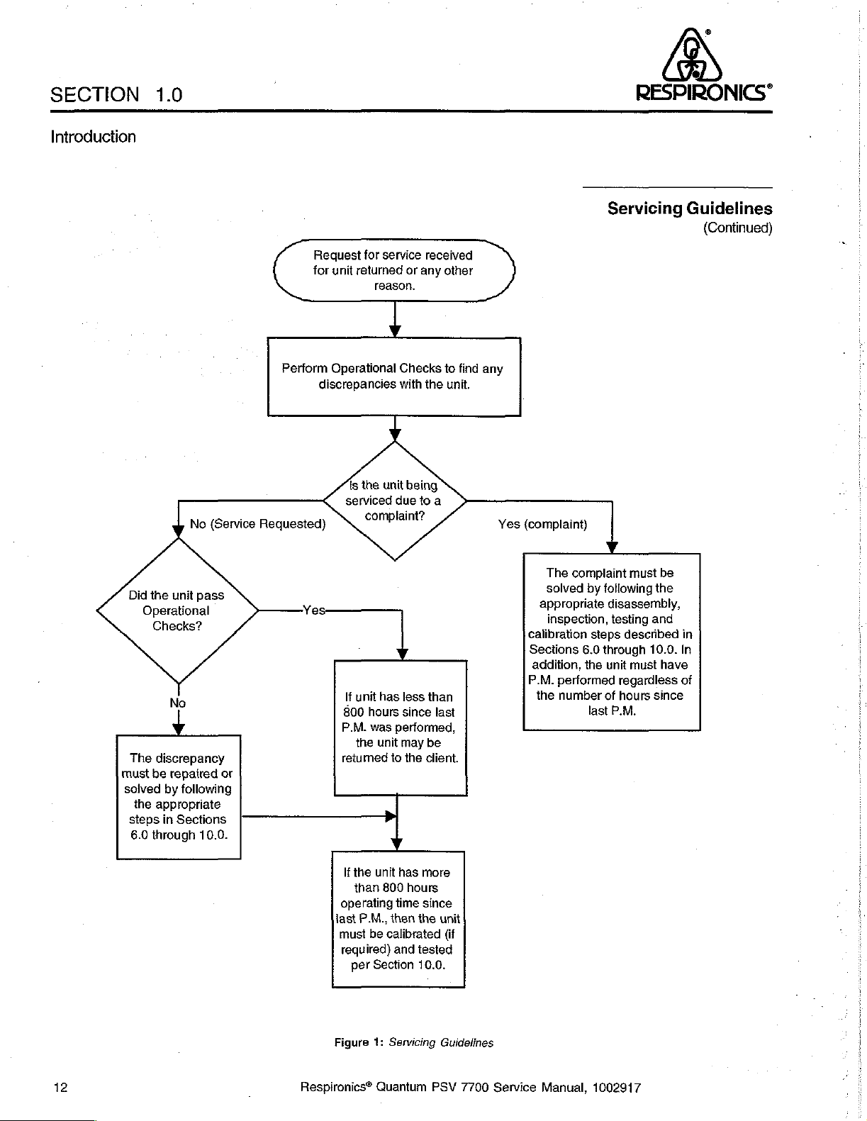
Servicing
Guidelines
W
A unit
passes
operation
adjustments
cover.
If
the
Section
Sections
performed,
A
unit
installed.
Refer
guidelines.
otherthan;
unit
is
5.0
to
6.0
regardless
automatically
to
the
Operational
that
do
being
find
through
flow
chart
internal
not
require
serviced
any
other
10.0,
including
of
the
fails
operational
on
the
Checks
battery
due
to a complaint,
discrepancies
number
next
if
no
replacement,
disassembly
Preventive
of
hours
checks
page
for a further
discrepancy
or
other
of
the
unit
perform
with
unit
operation.
Service
remaining.
if
any
mandatory
description
is
discovered
minor
repairs
other
than
the top
Operational
The
MUST
aiso
be
ECO
of
servicing
in
unit
Checks
steps
is
not
or
in
in
Respironics®
Quantum
PSV
7700
Service
Manual,
1002917
11
Page 14
SECTION
Introduction
1.0
RESPIRONICS"
Did
Operational
The
must
solved
the
steps
6.0
No (Service
the
unit
pass
Checks?
No
y
discrepancy
be
repaired
by
following
appropriate
in
Sections
through
10.0.
or
Reguested)
Reguest
for
Perform
discrepancies
Yes:
for
service
unit
returned
reason.
Operational
ls
the
unit
serviced
complaint?
If
unit
has
800
hours
P.M.
was
the
unit
retumed
If
the
unit
than
800
operating
last
P.M.,
must
be
required)
per
Section
received
or
any
other
Checks
with
due
the
being
to
a
to
less
than
since
last
performed,
may
be
to
the
client.
has
more
hours
time
since
then
the
unit
calibrated
and
(if
tested
10.0.
find
any
unit.
Yes
(complaint)
The
complaint
solved
appropriate
inspection,
calibration steps
Sections
addition,
P.M.
the
6.0
performed
number
Servicing
must
by
following
disassembly,
testing
described
through
the
unit
must
regardless
of
hours
last
P.M.
Guidelines
be
the
and
in
10.0.
In
have
of
since
(Continued)
12
Figure
1:
Servicing
.
Respironics®
Quantum
Guidelines
PSV
7700
Service
Manual,
1002917
Page 15

RESPIRONICS®
SECTION
Introduction
1.0
(This
page
intentionally
left
blank)
Respironics®
Quantum
PSV
7700
Service
Manual,
1002917
13
Page 16
SECTION
2.0
RESPIRONICS’
Wamings
and
Cautions
Warnings
Warnings
Cautions
ESDS
Warnings
and
Cautions
and
Cautions
Section
2.0
14
Respironics®
Quantum
PSV
7700
Service
Manual,
1002917
Page 17
RESPIRONICS*
SECTION
2.0
Warnings
This
is a non-continuous
breathing.
it
is
Airflow
selection
may
The
moisture
The
contamination.
DO
Never
Do
notuse
or
Respironics
not
intended
generated
result
use
of a water
from
use
of
NOT
use
operate
It
must
of
certain
in a situation
entering
bacteria
the
this
this
device
immediately.
not
be
used
to
provide
by
this
combinations
where
trap
and/or
the
ventilator.
filters
are
QUANTUM
device
if
ithas
if
ventilator
as a ventilator
the
device
and
total
ventilatory
is
limited
of
settings
pressure
hydrophobic
recommended
PSV
in
the
presence
the
power
cord
been
dropped
Warnings
is
intended
that
supports
requirements
to
(i.e.,
support
filter
to
ensure
is
damaged.
or
damaged.
to
150
liters
high
rate
levels
cannot
is
recommended
client
of
flammable
Contact
and
augment
or
sustains
of
the
per
minute.
and
short
be
safety
anesthetics.
Cautions
patient
life,
and
patient.
The
risetime)
obtained.
to
prevent
from
cross
your
dealer
Cautions
Use
only
an
identically
Oxygen
oropen
before
the
Do
Do
Always
Performance
The
properoperation.
Connect
Quantum
above
vigorously
flame
turning
device
nat
block
not
kink
unplug
Quantum
the
PSV
40°C.
when
on
off.
Do
any
or
crimp
the
verification
PSV
Quantum
performance
rated
accelerates
using
supplemental
the
supplemental
not
smoke
air
intake
air
outlet
Quantum
of
must
be
PSV
to a grounded
and
sized
fuse
combustion.
oxygen.
oxygen.
within 6 feet
vents.
hoses.
PSV
before
the
Quantum
periodically
is
affected
checked
at
for
replacement.
Keep
this
This
Turn
off
the
(2
meters)
cleaning
PSV
must
the
be
and
+
hospital
temperatures
grade
device
away
device
must
oxygen
of
this
before
unit.
enclosure.
performed
maintained
outlet
only.
below
5°C
from heat
be
running
turning
before
use.
to
ensure
and
Respironics®
Quantum
PSV
7700
Service
Manual,
1002917
15
Page 18
SECTION
2.0
RESPIRÔNICS*
Warnings
+
Replace
blow
fuse,
*
Positioning
on
the
¢
Verity
that
*
Connect
Recording
not
insert
*
All
ESDS
shipping
ㆍ
All
persons
resistive
‧
Coverall
work
surfaces
and
Cautions
the
back
5mm x 20mm.
the
rear
panel.
the
alarms
only
Model
Devices
any
devices
items
must
bags,
foam,
handling
grounded
ESDS
and
panei
Quantum
are
7703
into
into
be
or
. 。
ESDS
wrist
bench
tops
equipment
shipping
PSV
fuse,
must
operational.
Remote
the
signal
output
the
signal
stored
tote
bins.
items
strap.
with
in
approved
must
grounded
to
earth
as
required,
not
block
Control
part
input
be
grounded
conductive
ground.
the
cables
(SOP)
part
(SIP)
with a 3-amp
air
intake
or
other
ofthe
Quantum
of
the
250V
ports
certified
Quantum
conductive packaging,
.
via a 1
mats
Meg
and
ohm
connect
fast
located
Sleep
PSV.
Do
PSV.
tubes,
ail
[170770
ESDS
and
Cautions
(Continued)
σσ
Warnings
Cautions
σ
.
.
s
Transport
container.
ο:
DONOT
tubes
* © DONOT
electronic
e
Never
unattended
*
‘Avoid
styrofoam
+
Use
only
grounded
+
Use
only
“antistatic”
procedures.
all
assemblies
use
cellophane
together.
handle
parts.
place
ESDS
in
an
cellophane
coffee
ESD
safe
DIP
installation
properly
quick-chill
ESDS
items
items
open
area.
wrappers,
cups,
solder
designed
sprays
containing
adhesive
by
their
on
ungrounded
synthetic
etc.
when
suckers,
tools.
heat
during
ESDS
items
tape
to
wrap
DIP
pins
or
mix
surfaces
carpeting,
working
grounded
lamps,
with
soldering
heat
chambers,
troubleshooting
in a conductive
(dual
in-line
them
with
other
or
leave
them
warm
or
cool
ESDS
items.
irons,
and/or
or
stress
bag
package)
routine
air
blasts,
and
testing
or
16
Respironics®
Quantum
PSV
7700
Service
Manual,
1002917
Page 19
RESPIRONICS"
SECTION
2.0
ESDS
and
(Continued)
Warnings
Cautions
*
The
and
Controller
CPU
Display
Power
Sensor
Encoder
following
require
special
PCB
PCB
PCB
Supply
PCB
PCB
assemblies
handling:
PCB
in
the
Quantum
Warnings
PSY
are
easily
and
Cautions
damaged
by
ESD
Respironics®
Quantum
PSV
7700
Service
Manual,
1002917
17
Page 20
SECTION
3.0
RESPIRONICS“
Specifications
and
Alerts
Specification
Front
Panel
Controls
Performance
Physical
Power
Output
Aleris
Front
Panel
Rear
Panel
Rear
Panel
Power
Patient
System
Specification
Specifications
Requirements
Signals
Visual
Visual
Alert
Alert
Alert
and
Alarms
Indicators
Indicators
Section
3.0
18
Respironics®
Quantum
PSV
7700
Service
Manual,
1002917
Page 21
RESPIRONICS"
SECTION
3.0
Front
Panel
Controls
Performance
Specifications
Power
On,
Off
Alert
Status
Power
Pressure
Failure,
cmH,0
Mode
Selection
CPAP,
Spontaneous,
Estimated
Peak
Flow,
Patient
Settings
CPAP/EPAP,
CPAP/EPAP
2-25
cmHL.O
IPAP
Range
2 — 80
cm
2-35
cm
2—
37
em
Patient
Spontaneous/Timed
Parameters
Minute
Volume,
IPAP,
Risetime,
Pressure
H,0,
(Domestic)
HO,
(35
ст
H,O,
(International
Leak,
Range
H,O
System
Tidal
Rate, % 1
.
Unit)
Unit)
Failure/Firmware
Volume,
Breath Rate
Time
Specifications
Check
and
Failure
Alerts
Respironics®
Quantum
PSV
7700
Service
Pressure
1
cmH,0
Pressure
+
0.7
+
0.0/ - 0,7
Pressure
0.1
seconds
(10 - 90%
Risetime
0.1
to
(10-90%
Rate
4-40
Breath
+ 1 BPM
%|
Time
10 — 90 % of
Manual,
Control
Accuracy
at
zero
Response
of
Control
0.9
seconds
of
Control
BPM
Rate
Control
1002917
Resolution
flow
from
zero
pressure)
Range
pressure)
Range
Accuracy
Range
total
flow
Time
(Min)
in
increments
breath
time
measured
of
at
0.1
150
LPM
seconds
19
Page 22
SECTION
3.0
RESPIRONICS“
Specifications
*
FlowTiigger
Inspiration
and
Expiration
e
%l
Time
Accuracy
+1%
e
+
+
Minimum
Minimum
Maximum
Flow
Limit
150
LPM
Height
8
Width
12.75"
Expiration
Inspiration
Inspiration
20.5
31.9
Alerts
0.25
Peak
Time
Time
cm
cm
liters
Flow
Time
second
per
x.75
500
200
3
sec
msec
msec
Physical
Performance
Specifications
(Continued)
μα
Specifications
*
Length
13"
+
Weight
15.73
lbs.
16.7lbs.
‧
Voltages
120
100—
200 — 240
‧
Currentconsumption
300VA
‧
Operating
40°C
5°-
+
Storage
and
Temperature
Humidity
Barometric
32.6
cm
7.15
kg
7.6kg
50/60
at
VAC
VAC
at
50/60
Temperature
Transport
Pressure
Hz
Hz
Conditions
-20°-
10%
oo
790—525
60°C
Non-condensing
95%
—
mmHg
>
Power
Reguirements
=
Operating/Storage
Requirements
20
Respironics®
Quantum
PSV
7700
Service
Manual,
1002917
Page 23
RESPIRONICS*
SECTION
3.0
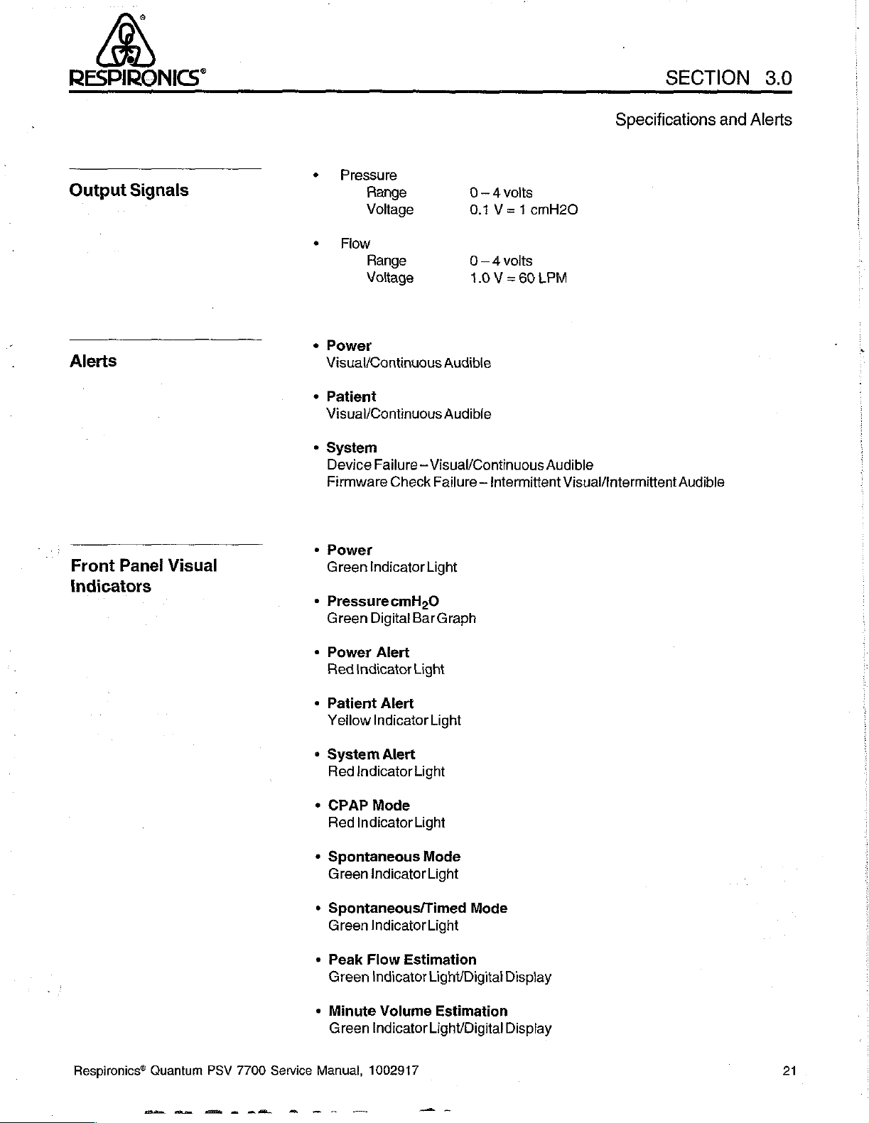
Output
Alerts
Signals
‧
Pressure
Range
Voltage
*
Flow
Fange
Voltage
*
Power
Visual/Continuous
+
Patient
Visual/Continuous
*
System
Device
Firmware Check
Failure — Visual/Continuous
0-4
vois
0.1
V= 1 cmH2O
0—4volis
1.0 V =
60
LPM
Audible
Audible
Audible
Failure — Intermittent
Specifications
Visual/tntermittent
Audible
and
Alerts
.
Front
Panel
Indicators
Visual
*
Power
Green
Indicator
*
PressurecmH,0
Green
+
Power
Bed
+
Patient
Yellow
+
System
Red
+
CPAP
Red
*
Spontaneous
Green
*
Spontaneous/Timed
Green
*
Green
Indicator
Indicator
Indicator
Peak
Digital
Bar
Alert
Light
Alert
Indicator
Alert
Light
Mode
Light
indicator
Indicator
Flow
Estimation
Indicator
Light
Graph
Light
Mode
Light
Mode
Light
Light/Digitat
Display
Respironics®
Quantum
PSV
7700
Service
ーー
+
Minute
Green
Manual,
Volume
Indicator
1002917
~
Estimation
Light/Digital
一
Display
21
Page 24
SECTION
3.0
RESPIRONICS”
Specifications
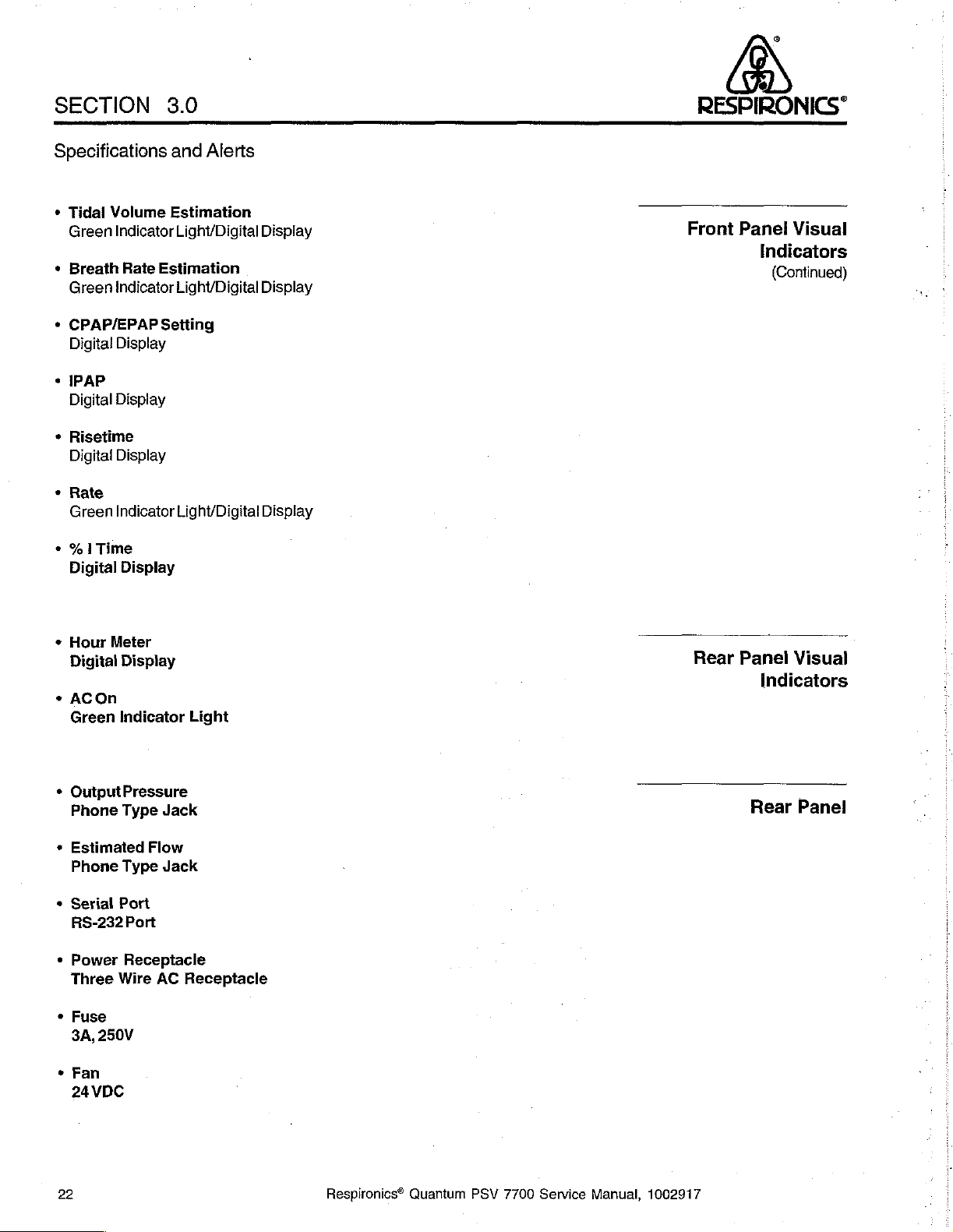
e
Tidal
Volume
Green
Indicator
*
Breath
Green
*
CPAP/EPAP
Digita!
*
IPAP
Digital
*
Risetime
Digital
*
Rate
Green
+
%1Time
Digital
Rate
Indicator
Display
Display
Display
Indicator
Display
and
Estimation
Light/Digital
Estimation
Light/Digital
Setting
Light/Digital
Alerts
」
Display
Display
Display
Front
TTT
Panel
Visual
Indicators
(Continued)
+
Hour
Meter
Digital
«
ACOn
Green
*
OutputPressure
Phone
+
Estimated
Phone
*
Serial
RS-232
*
Power
Three
*
Fuse
3A,
*
Fan
24
Display
Indicator
Type
Type
Port
Port
Receptacle
Wire
250V
VDC
Jack
Flow
Jack
AC
Light
Receptacle
Rear
Panel
Visual
Indicators
Rear
Panel
22
Respironics®
Quantum
PSV
7700
Service
Manual,
1002917
Page 25
RESPIRONICS"
SECTION
3.0
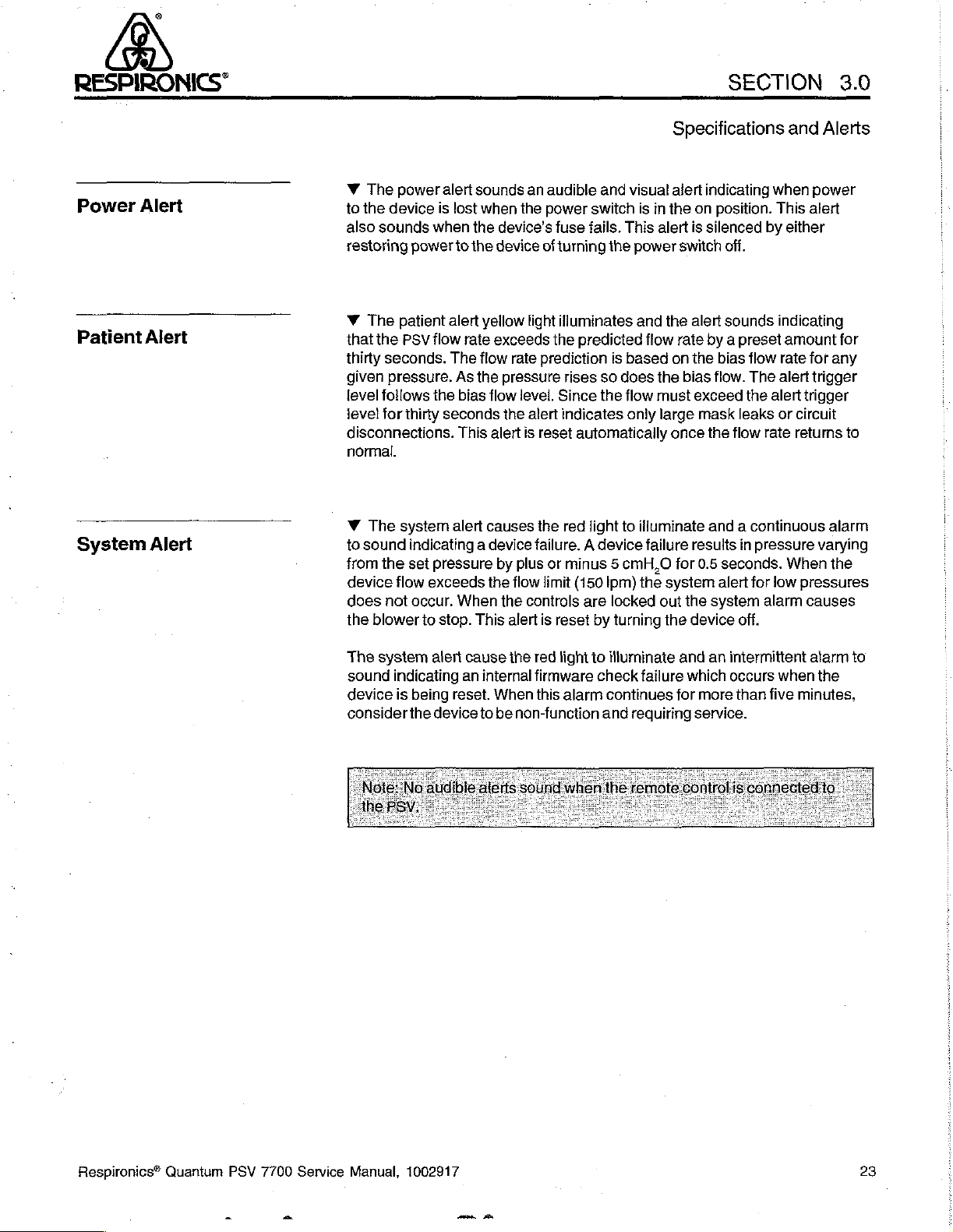
Power
Patient
System
Alert
Alert
Alert
Y
The
power
alert
to
the
device
also
sounds
restoring
w
The
that
the
thirty
seconds.
given
pressure.
level
follows
level
for
disconnections.
normal.
W
The
to
sound
from
the
device
does
not
the
blower
is
lost
when
power
fo
patient
PSV
flow
the
thirty
alert
The
As
bias flow
seconds
This
system
alert
indicating a device
set
pressure
flow
exceeds
occur.
When
to
stop.
sounds
when
the
the
yellow
rate
exceeds
flow
the
alert
causes
the
This
an
audible and
the
power
device's
device
fuse
of
turning
light
illuminates
the
rate
prediction
pressure
the
level.
Since
alert
indicates
is
reset
rises
the red
failure. A device
by
plus
or
minus 5 cmH,O
flow
limit
the
controls
alert
is
reset
visual
switch
fails.
predicted
the
is
so
the
is
This
power
and
based
does
flow
only
in
alert
the
flow
the
must
large
automatically
light
to
illuminate
failure
(150
Iprn)
the
system
are
locked
by
turning
out the
the
Specifications
alert
indicating
the
on
position.
is
silenced
switch
off.
alert
sounds
rate
by a preset
on
the
bias
bias
flow.
exceed
mask
leaks
once
the
flow
when
This
by
indicating
amount
flow
rate
The
alert
the
alert
or
rate
and
either
and a continuous
results
for
device
0.5
seconds.
alert
system
in
pressure
When
for
low
alarm
off.
Alerts
power
alert
for
for
any
trigger
trigger
circuit
returns
to
alarm
varying
the
pressures
causes
The
system
sound
device
consider
indicating
is
being
the
alert
cause
an
reset.
device
the
internal
When
to
be
non-function
red
light
to
firmware
this
alarm
illuminate
check
failure
continues
and
requiring
and
which
for
more
service.
an
intermittent
occurs
than
when
five
alarm
the
minutes,
to
Respironics®
Quantum
PSV
7700
Service
Manual,
1002917
23
Page 26
SECTION
4.0
RESPIRONICS“
Troubleshooting
Chart
Section
4.0
24
Respironics®
Quantum
PSV
7700
Service
Manual,
1002917
Page 27
RESPIRONICS”
SECTION
4.0
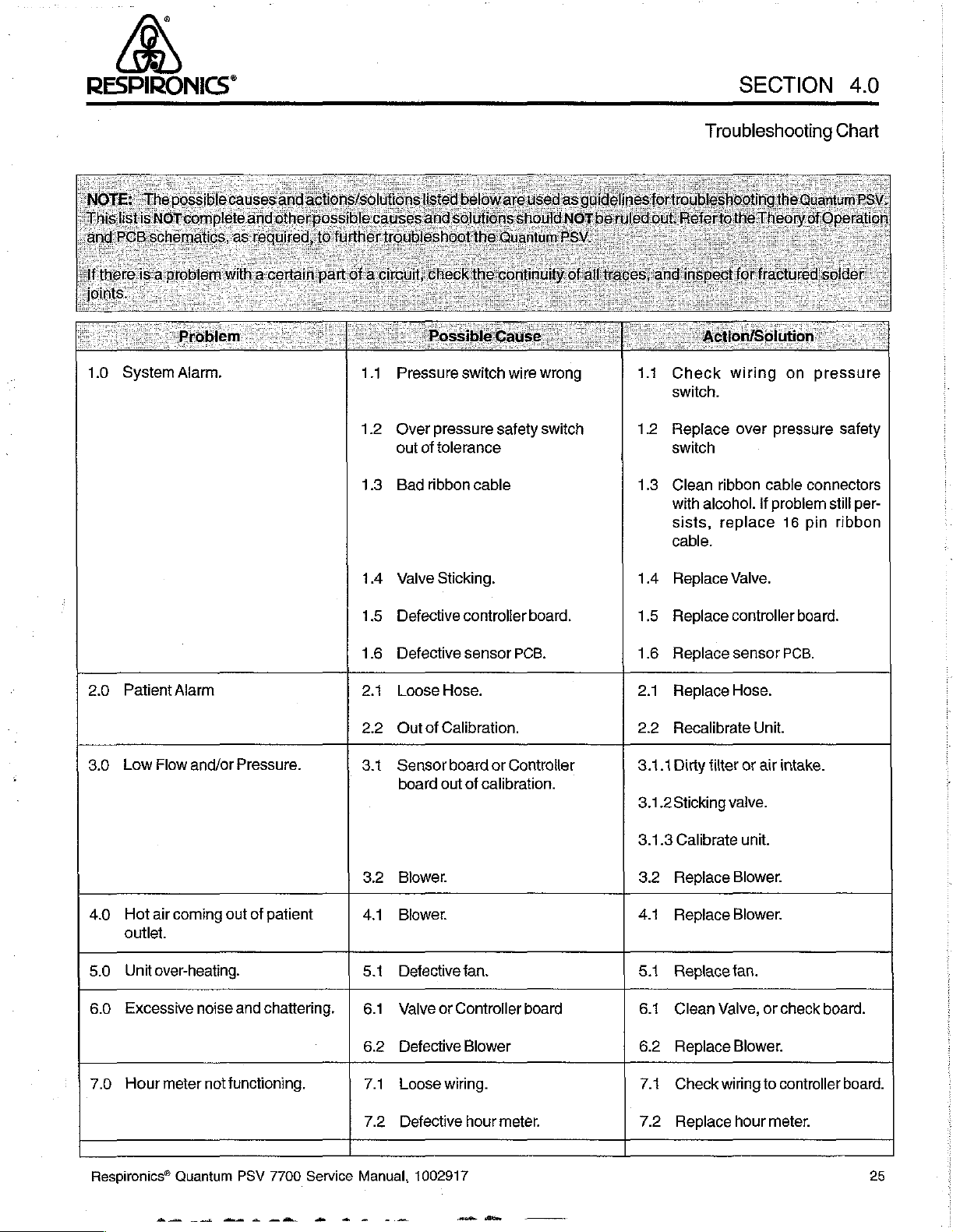
1.0
System
Alarm.
Troubleshooting
Chart
1.1
1.2
1.3.
1.4
Pressure
Over
out
Bad
Valve
switch
pressure
of
tolerance
ribbon
Sticking.
safety
cable
wire
wrong
switch
1.1
1.2
1.3
1.4
Check
switch.
Replace
switch
Clean
with
alcohol.
sists,
cable.
Replace
wiring
over
ribbon
if
replace
Valve.
on
pressure
cable
connectors
problem
16
pin
pressure
safety
still
per-
ribbon
2.0
3.0
4.0
5.0
6.0
7.0
Patient
Low
Hot
outlet.
Unit
Excessive
Hour
Alarm
Flow
air
coming
over-heating.
meter
and/or
Pressure.
out
noise
and
not
functioning.
of
patient
chattering.
1.5
1.6
2.1
22
3.1
32
41
5.1
6.1
6.2
7.1
Defective
Defective
Loose
Hose.
Outof
Calibration.
Sensor
board
Blower.
Blower.
Detective
Valve
Defective
Loose
board
out
or
Controller
wiring.
controlier
sensor
of
calibration.
fan.
Blower
board.
PCB.
or
Controller
board
1.5
Replace
1.6
Replace
2.1
Replace
22
Recalibrate
3.1.1
Dirty
3.1.2Sticking
3.1.3
Calibrate
8.2
Replace
4.1
Replace
5.1
Replace
6.1
Clean
6.2
Replace
7.1
Check
controller
sensor
Hose.
filter
valve.
Blower.
Blower.
fan.
Valve,
Blower.
wiring
Unit.
or
air
unit.
or
check
to
controller
board.
PCB.
intake.
board.
board.
Respironics®
Quantum
m
mk
m
PSV
7700
Service
7.2
Defective
hour
Manual,
ω--
1002917
meter.
7.2
Replace
hour
meter.
25
Page 28
SECTION
4.0
RESPIRONICS“
Troubleshooting
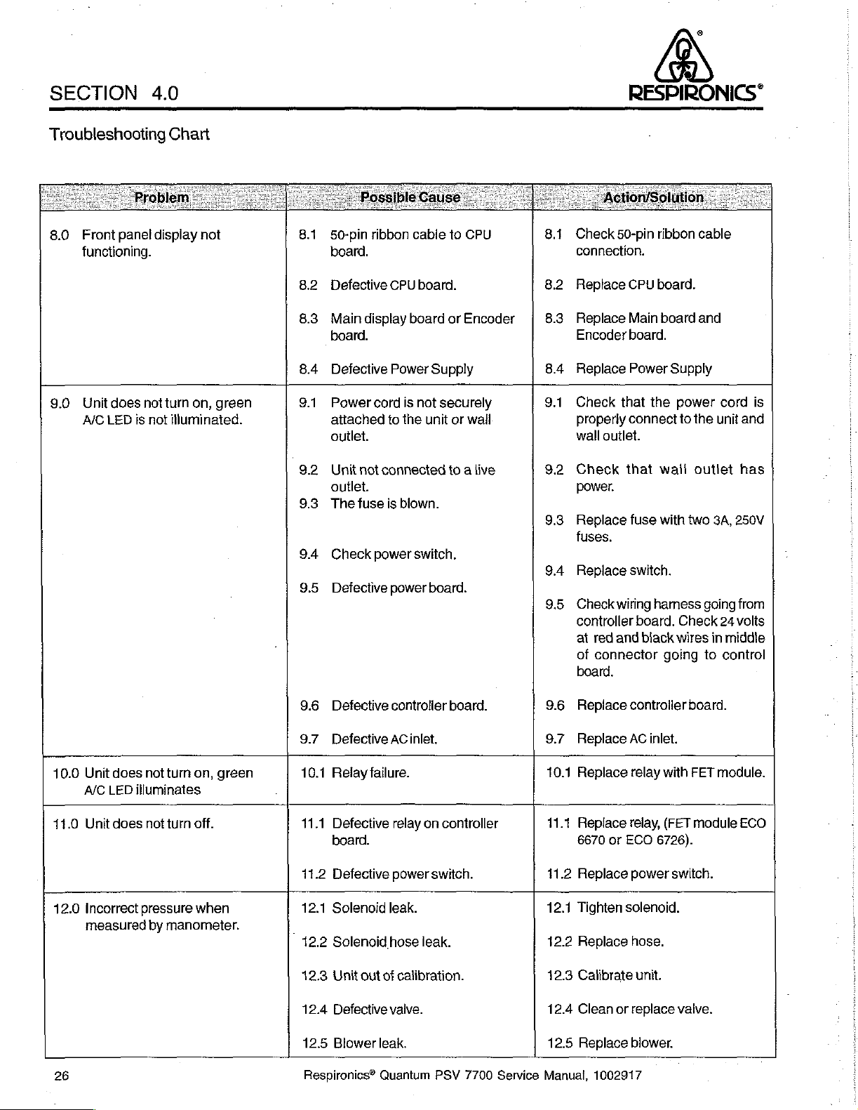
8.0
Front panel
functioning.
9.0
Unit
does
not
A/C
LED
is
not
Chart
display
not
turn
on,
illuminated.
green
8.1
50-pin ribbon
board.
8.2
Defective
8.3
Main
board.
8.4
Defective
9.1
Power
attached
outlet.
92
Unit
outlet.
9.3.
The
9.4
Check
9.5
Defective
CPU
display
Power
cord
to
not
connected
fuse
is
power
power
cable
board.
board
Supply
is
not
the
unit
blown.
switch.
board.
to
CPU
or
Encoder
securely
or
wall
to a live
8.1
Check
connection.
8.2
Replace
8.3
Replace
Encoder
8.4
Replace
9.1
Check
properly
wall outlet.
9.2
Check
power.
9.3
Replace
fuses.
9.4
Replace
9.5
Check
controller
at
of
board.
50-pin
CPU
Main
board.
Power
that
the
connect
that
fuse
switch.
wiring
board.
red
and
biack
connector
ribbon
cable
board.
board
and
Supply
power
to
the
wali
outlet
with
two
harness
Check
wires
going
cord
unit
3A,
going
24
in
middle
to
control
is
and
has
250V
from
volts
10.0
Unit
does
not
turn
on,
green
A/C
LED
11.0
Unit
12.0
Incorrect
measured
26
illuminates
does
not
pressure
by
turn
off.
when
manometer.
9.6
Defective
9.7
Defective AC
10.1
Relay
11.1
Defective
board.
11.2
Defective
12.1
Solenoid
12.2
Solenoid
12.3
Unit
12.4
Defective
12.5
Blower
Respironics®
controller
failure.
relay
power
leak.
hose
out
of
calibration.
valve.
leak.
Quantum
inlet.
on
controller
switch.
leak.
PSV
board.
7700
9.6
Replace
9.7
Replace
10.1
Replace
11.1
Replace
6670
41.2
Replace
Tighten
12.1
12.2
Replace
12.3
Calibrate
12.4
Clean
12.5
Service
Replace
Manual,
controller
AC
relay
relay,
or
ECO
power
solenoid.
hose.
or
replace
blower.
1002917
inlet.
with
(FET
6726).
switch.
unit.
board.
FET
module
valve.
module.
ECO
Page 29
RESPIRONICS”
SECTION
4.0
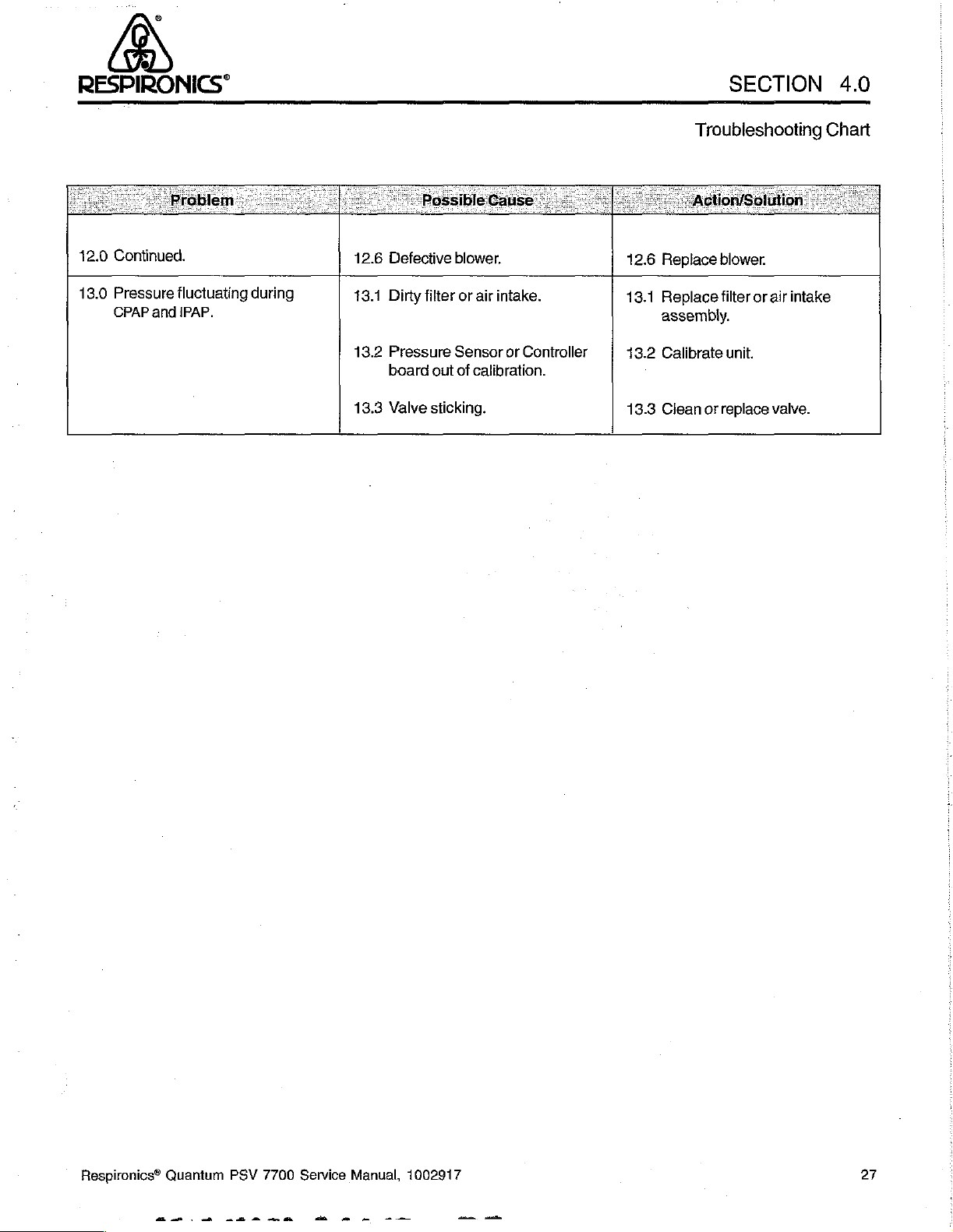
12.0
Continued.
13.0
Pressure
CPAP
fluctuating
and
IPAP.
during
12.6
Defective
13.1
Dirty
13.2
Pressure
board
13.3
Valve
blower.
filter
or
air
Sensor
out
of
calibration.
sticking.
intake.
or
Controller
12.6
Replace
13.1
Replace
assembly.
13.2
Calibrate
13.3
Ciean
Troubleshooting
blower.
filter
or
air
unit.
or
replace
valve.
Chart
intake
Respironics®
Quantum
PSV
7700
Service
Manual,
1002917
27
Page 30
SECTION
5.0
RESPIRONICS”
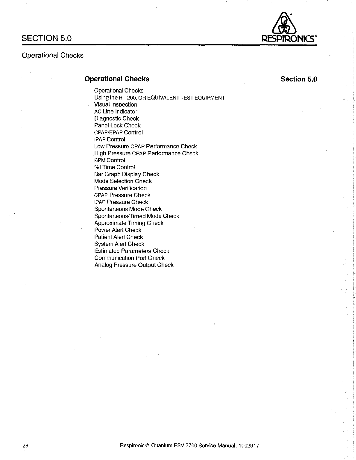
Operational
Checks
Operational
Operational
Using
the
RT-200,
Visual
Inspection
AC
Line
Indicator
Diagnostic
Panel
Lock
CPAP/EPAP
IPAP
Control
Low
Pressure
High
Pressure
BPM
Control
Yel
Time
Control
Bar
Graph
Mode
Selection
Pressure
CPAP
IPAP
Spontaneous
Spontaneous/Timed
Approximate
Power
Patient
System
Estimated
Communication
Analog
Verification
Pressure
Pressure
Alert
Alert
Alert
Parameters
Pressure
Checks
Checks
OR
EQUIVALENT
Check
Check
Control
CPAP
Performance
CPAP Performance
Display
Check
Check
Check
Gheck
Mode
Timing
Check
Check
Port
Output
Check
Check
Mode
Check
Check
Check
Check
Check
TEST
Check
Check
EQUIPMENT
.
Section
5.0
28
Respironics®
Quantum
PSV
7700
Service
Manual,
1002917
Page 31

RESPIRONICS“
SECTION
5.0
Operational
Using
an
RT-200,
EQUIVALENT
EQUIPMENT
Checks
OR
TEST
Y
Operational
of
the
unit.
If a unit
requiring
performed.
A
unit
minor
passes
operation.
Y
Aproperly
Calibration
reassembly
Quantum
Service
TestName
CPAP
Pressure
IPAP
Pressure
Pressure
Flow
Verification
Measuremenis
Checks
fails
repairs
Operational
calibrated
Analyzer
tests,
unit
Manual.
Check
Check
are
used
any
the
steps
RT-200,
may
be
testing,
to
of
these
in
Checks
OR
used
to
or
calibration
RT-200,
find
any
discrepancies
checks,
Sections
if
no
discrepancy
EQUIVALENT
perform
procedures
Test
No.
12
12
21
36
Operational
other
than a discrepancy
6.0
through
is
TEST
EQUIPMENT
Operational
as
Checks
with
the
operation
10.0
MUST
be
discovered
Checks,
described
Readings / Scale
250cm
250
cm
20
psi
180
pm
H,O
H,O
in
in
the
unit
Visual
AC
Line
Inspection
Indicator
Y
inspect
the
case
panel
not
scratched
Y
Connect
into
an
that
the
is
knobs
AC
unit
the
unit
securely
are
secure
or
damaged
the
AC
outlet.
The
is in
standby.
case
for
fastened.
and
power
cord
green
scratches,
Check
in
good
condition.
in
any
way.
to
the
AC
LED
on
dents,
that
the
back
the
or
fan,
of
the
rear
other
hour
Check
unit.
panel
damage.
meter,
that
Plug
the
the
Check
and
displays
power
illuminates
that
front
are
cord
indicating
Respironics®
Quantum
PSV
7700
Service
Manual,
1002917
29
Page 32

SECTION
5.0
RESPIRONICS”
Operational
W Press
displays
LED
unit
15
W
simultaneously
settings
of
the
display.
vw
Verify
25
Change
the
cmH,O.
the
illuminate
displays.
is
operating.
seconds.
Lock
the
is
Estimated
With
the
the
CPAP/EPAP
omH,O.
the
CPAP/EPAP
On/Off
The
Check
panel
not
unit
unit
Checks
button
briefly,
green
Adj
is
that
by
pressing
until
Loc
possible
Parameters
in
CPAP
control
mode
control
to
start
followed
LED
next
displayed
the
unis
both
appears
in
the
locked
buttons
mode,
verify
range
to
Spont,
range
by
the
unit.
The
immediately
to
the
On/Off
on
the
Estimated
cooling
in
of
the
the
state.
fan
Estimated
display.
Unlock
simultaneously
that
the
by
setting
and
set
the
setting the
alert
sounds
by
iHlumination
button
Parameters
is
operating.
Parameters
Adjusting
the
until
CPAP mode
the
display
IPAP
control
display
from 2 cmH,0
and
all
of
all
illuminates
window
buttons
any
of
the
panel
by
pressing
Adj
appears
LED
is
from 2 cmH,O
to
30
cmH,O.
alert
other
when
the
for
system
both
in
the
illuminated.
to
Verify
to
25
Diagnostic
Panel
CPAP/EPAP
Lock
Check
Check
Control
У
With
the
IPAP
control
cmH,O
Set
for
CPAP/EPAP
CPAP/EPAP
Continue
decrease.
unit
range
35
value.
to
slowly
cm
in
Spont
H,O
to
10
Verify
lower
by
setting
units,
cmH,O.
mode,
and
Slowly
that
the
the
IPAP
set
the
37
CPAP
the
CPAP/EPAP
display
cm
H,O
lower
mode
value.
The
control
to 2 cmH,O,
for
International
the
IPAP
range
indicator
CPAP/EPAP
to 2 cmH,O.
and
to
Units).
until
is
flashing.
value
30
cmH,O
it
equals
must
Verify
the
also
(35
IPAP
Control
30
Respironics®
Quantum
PSV
7700
Service
Manual,
1002917
Page 33

RESPIRONICS*
SECTION
5.0
BPM
%I
Time
Bar
Graph
Check
Mode
Control
Control
Display
Selection
¥V
Set
the
value
of
40
BPM.
Y
Set
Timed.
control
Y
The
display
V
Press
Occlude
the
outlet
each
mode:
mode
10.
Verify
the
mode
The % i
range
by
bar
graph
in
each
the
Up
the
outlet
for
SPONT/TIMED
of
the
the
of
the
Time
displays
setting
display
of
the
and
for
unit
to
BPM
control
unit
to
the
display
must
control
Down
arrow
CPAP
and
mode.
Spont/Timed.
range
by
CPAP.
the
default
be
within
Set
from
the
value
10%
+1
modes.
keys
under
SPONT
The
following
modes,
The
BPM
setting
mode
of
to
90%.
cm
H,O
the
Mode
and
LED’s
Operational
displays
the
of
the
33%.
to
the
only
the
display
unit
to
Verify
the % |
digital
Select
partially
are
illuminated
Checks
default
from 4 BPM
Spont/
Time
CPAP/EPAP
section.
occlude
during
to
CPAP
SPONT
SPONT/TIMED
Set
CPAP/EPAP
the
following
Rate
Select
are
Spontaneous/Timed
displayed:
Risetime
CPAP
CPAP
SPONT
to
system
CPAP/EPAP
IPAP
Risetime
“el
Time
CPAPEPAP
IPAP
Rate
%
Time
LED
_LED
SPONT/TIMED
(CPAP
settings
2cm
H,O,
settings
2cmH,O
2cmHO
0.5
Blank
Blank
2cmHO
2cmHO
illuminated
flashes
LED
illuminated
LED
are
then
are
displayed:
sec
mode.
0.5
sec
10
33
LED
flashes
identical)
select
the
Verify
that
illuminated
when
CPAP/EPAP
Spontaneous
the
following
mode.
system
and
IPAP
Verify
settings
that
Respironics®
Quantum
PSV
7700
Service
Manual,
1002917
31
Page 34

SECTION
5.0
RESPIRONICS”
Operational
Set
the
system
IPAP
CPAP/EPAP
Risetime
Rate
%l
Time
Turn
off
the
unit
tum
on
the
unit.
Change
settings
Set
displayed:
the
are
CPAP/EPAP
IPAP
Risetime
Rate
%I
the
unit
unit
displayed:
Time
mode
Checks
settings
and
Verify
mode
to
to
verify
that
to
CPAP
the
following:
20
cm
H,0
10
em
H,0
0.3
sec
15
40
that
all
LEDs
the
previous
Spontaneous
10
cm
H,0
20
cm
HO
0.3
sec
Blank
Blank
and
verify
are
system
and
that
blank.
verify
the
following
Wait
thirty
settings
that
the
system
seconds
are
displayed.
following
settings
and
system
are
Mode
Selection
(Continued)
CPAP/EPAP
IPAP
Risetime
Rate
Yel
Set the
settings
Vv
hose.
figure
unit
are
CPAP/EPAP
IPAP
Risetime
Rate
%l
Connect
Connect
2).
CPAP/EPAP
IPAP
Risetime
Rate
ol
Time
Time
mode
displayed:
Time
the
restricted
the
Set
the
unit
10
cm
HO
Blank
Biank
Blank
Blank
to
Spontaneous/Timed
10
cm
HO
10
cm
HO
0.5
sec
10
33
adapter
/s"
tubing
to
on
the
following
the
2cmHO
30
cm
HO
0.1
seconds
15
BPM
50
and
verify
(TS-7700-31)
flow
restrictor
system
settings:
that
the
to
the
end
of
to a pressure
following
the
Quantum's
gauge,
system
(see
Pressure
Verification
32
Respiranics®
Quantum
PSV
7700
Service
Manual,
1002917
Page 35

RESPIRONICS”
SECTION
5.0
Pressure
(Continued)
CPAP
Pressure
Verification
Check
Verify
high
pressure
W
Connect
1/8”
tubing
that
the
the
on
low
is
flow
the
pressure
30
cm
restrictor
flow
restrictor
is 2 em
H,0 + 0.70
Flow
TS-7700-034
Figure
2:
Set-up
to
the
to a volume
H,0 + 0.70
cm
H,0.
Restricter
to
Measure
end
of
the
measuring
Operational
cm
H,O,
Pressure
Quantum’s
device,
and
verify
hose.
(see
Checks
that
they
Connect
figure
the
2).
IPAP
Pressure
Check
Select
display
the
CPAP mode
reads
25
cm
display a pressure
Set
the
CPAP
pressure
em
HO.
2
Set
the
CPAP
pressure
Y
Connect
the
1/8”
Select
to
the
the
flow
tubing
the
on
Spont/Timed
following:
CPAP/EPAP
IPAP
Domestic
international
35cm
H20
Risetime
Rate
%l
Time
on
the
H,O.
The
of
25
cm
to
10
to 2 cm
restrictor
the
flow
mode
2cm
H,0
Units
Units
Units
0.1
10
50
Quantum.
RT-200,
OR
H,O + 0.7
cm
H,O.
H,O.
Verify a pressure
to
the
end
restrictor
to a pressure
on
the
Quantum.
30cm
87cm
35cm
seconds
BPM
Set
the
CPAP/EPAP
EQUIVALENT
cm
Н.О.
TEST
Verify a pressure
of
the
Quantum’s
measuring
Set
the
H,O
H,0
H,0
EQUIPMENT
of
10
of 2 cm
outlet.
Quantum
knob
untii
cm
H,O + 0.7
H,O + 0.7
Connect
device.
parameters
the
must
HO.
Respironics®
Quantum
PSV
7700
Service
Manual,
1002917
33
Page 36

SECTION
5.0
RESPIRONICS“
Operational
Verify
that
the
Verify
that
the
illuminates
Reset
Proximal
Lung
Lung
Verify
Verify
illuminates
Y
Connect a flow
the
following
CPAP/EPAP
IPAP
Risetime
Rate
“el
during
the
Michigan
Resistance
Compliance
that
the
that
the
during
Time
Resistance
parameters:
Checks
five
breathing
forced
five
forced
breath
each
Lung
breathing
breath
each
restricterto
cycles
LED,
breath.
to
the
cycles
LED,
breath.
the
5
cm
H,O
15
cm
0.1
seconds
10
BPM
50
take
located
following
Rp5
Rp20
0.05
take
located
Quantum's
HO
30
seconds = 1
to
the
left
parameters:
30
seconds + 1
to
the
left
patient
second
of
the
second
of
the
outlet.
Rate
Rate
Set
to
complete.
display,
to
complete.
display,
the
unit
to
U
Do
Spontaneous/Timed
Mode
Approximate
Performance
_
Verification
Check
(Continued)
i
Timing
The
unit
defaults
H,O.
After 3 seconds + 0.5
to
for 3 seconds + 0.5
Set
the
Quantum
CPAP/EPAP
ΙΡΑΡ
to
Risetime
Rate
%l
Time
The
unit
defaults
H,0.
After 9 seconds + 0.5
to
for 3 seconds + 0.5
Set
the
Quantum
to
CPAP/EPAP
IPAP
Risetime
Rate
Sel
Time
The
unit
defaults
H,0.
After 1 second + 0.5
for 2 seconds + 0.5
to
the
EPAP
seconds,
seconds.
the
following
5cmH,0
15
0.1
5
BPM
25
the
EPAP
seconds,
seconds.
the
following
5cmH,O
15
0.1
20
66
the
EPAP
seconds,
seconds.
pressure,
parameters:
cm
H,O
seconds
pressure,
parameters:
cm
HO
seconds
BPM
pressure,
the
and
the
barograph
and
the
barograph
and
barograph
the
barograph
the
barograph
the
barograph
displays 5 cm
increases
displays 5 cm
increases
displays 5 cm
increases
to
to
to
15
15
15
cm
cm
cm
H,O
H,O
H,0
36
Respironics®
Quantum
PSV
7700
Service
Manual,
1002917
Page 37

RESPIRONICS“
SECTION
5.0
Power
Patient
Alert
Alert
Check
Check
w
With
the
alarm
must
illuminate
alarm
Y
Connect a flow
immediately.
must
parameters
CPAP/EPAP
IPAP
Risetime
Rate
%l
Time
Remove
seconds
flow
the
of
restricteron
unit
running,
sound
for
at
Plug
least
unplug
five
the
cease.
restricter(TS-7700-031)
to
the
following:
5
cm
H,O
30
cm
0.3
seconds
4
BPM
50
flow
restricterfrom
removing
the
the
flow
outlet
restrictor.
port.
the
AC
seconds,
AC
power
H,O
the
outlet
power
-
The
and
cord
to
the
port.
alert
Operational
cord
from
the
red
back
into
outlet
port.
The
alert
is
silenced
its
supply.
Power
its
supply.
Set
sounds
by
Checks
The
LED
must
The
the
within
30
replacing
the
System
Estimated
Check
Alert
Check
Parameters
Y
Set
the
Quantum
Connect a 10
outiet
port
of
The
alert
sounds,
seconds.
Y
Michigan
settings:
Set
Set
the
Proximal
Lung
Lung
the
system
To
unit
Lung
Resistance
Compliance
CPAP/EPAP
IPAP
Risetime
Rate
Yel
Time
Let
the
unit
stabilize
unit
displays
to
CPAP
mode.
cm
H,0
positive
the
unit.
Block
when
reset
the
alert,
mode
to
using a 22mm
Resistance Rps
pressure
the
exhalation
the
pressure
turn
off
Spontaneous/Timed.
hose.
Rp20
0.05
settings
the
following
for
to
one
the
following:
2
cm
H,O
25
cm
Н.О
0.1
seconds
10
BPM
25
minute
estimated
Set
the
CPAP
source
exerted
the
unit.
Set
the
(7300
port
on
exceeds 5 cmH,0
Connect
Michigan
before reading
parameters:
pressure
or
equivalent)
the
rear
panel
the
Quantum
Lung
to
displays.
to
20
cm
of
for 0.5
the
following
Verify
Η,Ο.
to
the
the
to
the
that
unit.
the
Respironics®
Quantum
PSV
7700
Service
Minute
Tidal
Rate
Manual,
Vol
Vol
1002917
17.80 + 5.34
1.780 + 0.534
10
37
Page 38

SECTION
5.0
RESPIRONICS”
Operational
Y
Connect a 7703
Verify
that
adjusting
on
the
Main
Unit.
displayed
Main
w
Using a mini-phono
tip
of
Select
Connect
7700-031)
+
0.7
Refer
measured
Unit
the
the
em
to
on
the
transmit
phono
CPAP
the
unit
and
3he”
H,O
on
the
following
at
the
Checks
Remote
the
controls
Verify
that
Remote
alert
plug,
mode
to a pressure
tubing,
the
above
Pressure
Unit.
signals
plug,
and
on
pressure
formula
pressure:
Unit
to
on
the
readings
Perform
to
connect
the
negative
the
unit.
measuring
(see
figure
gauge.
to
determine
Measured
10
the
the
the
Set
rear
panel
of
the
Remote
the
Remote
the
lead
the
2).
Verify
(cm
Unit
changes
on
the
Main
Unit
Alert
checks
Unit.
positive
device
H,0) _ voltage + 0.05
to
the
CPAP
that
the
voltage
lead
of a volt-meter
sleeve
pressure
using a flow
the
Quantum
match
to
verify
of
the
to
15
unit
pressure
measure
Main
Unit.
the
displays
those
that
the
to
the
phono
cm
plug.
Η,Ο.
restricter(TS-
is
15.0
range
volts
Communication
Analog
Output
Port
Check
Pressure
Check
38
Respironics®
Quantum
PSV
7700
Service
Manual,
1002917
Page 39

RESPIRONICS“
SECTION
5.0
Operational
Checks
(This
page
intentionally
left
blank)
Respironics®
Quantum
PSV
7700
Service
Manual,
1002917
39
Page 40

SECTION
6.0
RESPIRONICS"
Preventive
Service
Preventive
Preventive
Mandatory
Quality Control
Service
Engineering
Service
Procedures
Change
Check-Out
Orders
Procedures
(ECOs)
Section
6.0
40
Respironics®
Quantum
PSV
7700
Service
Manual,
1002917
Page 41

RESPIRONICS”
SECTION
6.0
_ .
Preventive
Service
Procedures
У
The
following
Quantum
Refer
these
Perform
*
Perform
Section
*
Check
*
Dual
PSV
to
Sections
procedures.
the
external
impeller
Inspect
Install a filter
If
inlet
Baffle
Air Inlet
Preventive
is
serviced.
4.0,
following
operational
5.0)
Filter
screenis
(p/n
Baffle
procedures:
verification
inlet
(new
siyle)
Air
intake
screen
dirty
600-07700-17)
according
Service
7.0,
and
10.0
check
filter
for
cleanliness.
blower,
Screen.
if
one
is
not
ornon-existent,
for
cleanliness.
to
the
procedures
for
detailed
and
note
Replace
(see
Section
lf
dirty,
replace
present.
check
procedures
Preventive
MUST
be
followed
information
any
7.0):
witha
blower
ifthe
in
Section
on
nonconformance
if
dirty.
new
iniet
screen
screen
7.0).
Service
each
performing
screen
is
on
dirty,
(p/n
the
replace
time
(see
7719).
Air
Inlet
a
the
Check
cleaniiness
and
valve
If
screen
impellers
Single
Impeller
Inspect
shells
and
Inspect
Inspect
hoses
as
+
Clean
valve
*
Incorporated
«
Replace
*Recalibrate
(see
battery,
Section
of
blowerhoses,
outlet
hose.
Replace
was
dirty,
remove
and
inside
of
both
(old
style)
blower,
foam
seals
to
ensure
no
air
external
blower
hose, valve
leaks.
inlet
Replace
filter
required.
per
valve
cleaning
all
mandatory
(see
blower/sensor/valve
ECO’s,
Section
10.0)
flow
as
required
upper
and
housings.
(see
proper
blower
backup
inlet
screen.
hose,
procedure,
(see
7.0)
sub-assembly
meter
lower
Section
seating
if
leaks
Replace
and
valve
(see
Section
per
bypass,
blower
housings.
7.0):
between
are
outlet
Section
8.0).
calibration
valveinlethose,
Clean
aluminum
detected.
filter
hose.
7.0)
blower
if
dirty.
Replace
procedure,
valve,
motor
Respironics®
Quantum
PSV
7700
Service
*
Troubleshoot
Manual,
1002917
and
repair
any
nonconformance
as
appropriate,
(see
Section
4.0)
41
Page 42

SECTION
6.0
RESPIRONICS
Preventive
Y
Install
all
applicable
8.0,
Engineering
ECO
#5147
ECO
#5465
ECO
#5557/5505
ECO
#5769
ECO
#5850
ECO
#6065
ECO
+6726/6670 | U31
Service
Change
Controller
Valve
Hour
CPU
Valve
Fuse
ECOs
including
Orders,
Board
Replacement
Meter
Board
Replacement
Drawer
Relay
those
for
detailed
Upgrade
Installation
Upgrade
Replacement
listed
below.
installation
for
New
instructions.
Style
Back
Refer
to
Section
Panels
Do
Mandatory
Change
Engineering
Orders
(ECOs)
42
Respironics®
Quantum
PSV
7700
Service
Manual,
1002917
Page 43

°
RESPIRONICS“
SECTION
6.0
Preventive
Service
(This
page
intentionally
left
blank)
Respironics®
Quantum
ニーー
PSV
7700
Service
一
人
Manual,
—
—
1002917
一 -
43
—
Page 44

SECTION
7.0
RESPIRONICS®
Disassembly,
Disassembly,
Inspection,
and
Inspection
Disassembly,
Case
Removal
Intake
Baffle
Blower
Fan
HourMeter
AC
Alarm
Controller
CPU
PowerBoard
Front
Front
Alarm
Display
Valve
Sensor
Pressure
Solenoid
Old
Noise
Final
Assembly
Removal
Inlet
Removal
Battery
Board
Board
Panel
Panel
Assembly
Board
Removal
Board
Switch
Removal
Style
Auxiliary
Unit
Reassembly
Removal
Reassembly
Inspection,
and
Inspection
Removal
Removal
Replacement
Removal
Removal
Removal
Removal
Bracket
Removal
Removal
Removal
Removal
Removal
Valves
and
Reassembly
and
Reassembly
Section
7.0
44
Respironics®
Quantum
PSV
7700
Service
Manual,
1002917
Page 45

RESPIRONICS"
SECTION
7.0
_
Disassembly,
Inspection,
Reassembly
Case
Removal
Inspection
and
and
Disassembiy,
Y
Follow
the
kits
the
Quantum
contain
instructions
PSV
7700. A list
all
the
parts
below
of
service
necessary
Y
Using a phillips
back
panel.
handle.
the
unit,
Remove
(see
Remove
the
figure).
screwdriver,
the
phillips
six
phillips
Carefully,
remove
for
disassembly,
kits
to
perform
R
remove
or
screws
hex
the
head
that
the
Inspection,
inspection,
may
be
found
the
specific
seven
screws
screw
from
secure
cover
the
from
case
the
and
Reassembly
and
reassembly
in
Section
11.0.
replacements.
ol
La
from
the
edge
underneath
to
unit.
the
the
bottom
of
These
of
the
of
Inspect
damage.
inside
the
unit
for
Figure
wire,
Figure
+
i
I
8
4:
Screw
hosing,
5:
Case
Screws
(p/n
533-1032-06)
Removal
loose
Removed
(14)
parts
and
assemblies,
and
other
Respironics®
Quantum
PSV
7700
Service
Manual,
1002917
45
Page 46

SECTION
7.0
RESPIRONICS“
Disassembly,
Y
Using a phillips
baffle
to
the
rear
or
other
damage.
Inspection,
screwdriver,
panel
of
Repiace
Air
Inlet
Baffle
(pin
600-07700-17)
and
the
unit.
as
necessary.
Figure
Reassembly
remove
6:
the
Inspect
1
и
intake
Baffle
four
the
screws
Intake
Removal
that
Baffle
for
Serows
(4)
secure
case
the
intake
cracking
Intake
Baffle
Removal
Y
Using a phillips
the
unit
that
secures
three
screws
the
bottom
Disconnect
ID
pressure
the
pressure
panel.
the
sensing
sensing
screwdriver,
the
from
inside
8-pin
connector
line
port
blower
from
the
exhaust
of
the
remove
assembly
unit
that
from
J7
assembly.
&
'
1
x
y
the
screw
in
place.
secures
of
Controller
port
of
the
Remove
Screws
(4)
(p/n
533-0614-00)
from
Remove
the
blower
Board.
blower.
the
the
bottom
the
remaining
assembly
Disconnect
Disconnect
assembly
from
Blower
Assembly
(pn600-077G0-11)
t
1
1
1.
panel
of
bracket
the
tubing
the
to
'/16”
from
unit.
Blower
Assembly
Removal
46
Figure
7:
Blower
Removal
Respironics®
Quantum
PSV
7700
Service
Manual,
1002917
Page 47

RESPIRONICS*
SECTION
7.0
Blower
Assembly
Removal
(Continued)
Using a phillips
to
the
blower
sensing
Check
port
the
screwdriver,
bracket.
to
the
three
necessary.
Single
Remove
bottom
Controller
Disconnect
Disconnect
box.
the
Disconnect
Remove
Impelier
the
of
the
board.
Disconnect
blower
box.
the
screw
unit.
the
ground
the
*/1e”
the
22mm
blower
Remove
blower
rubber
(Old
that
grommets
Style)
is
Disconnect
Cut
the
wire
ID
clear
the
'/e”
ID
clear
box
from
Disassembly,
remove
bracket.
located
cable
from
tubing
Green
tubing
the
the
single
Remove
for
Blower
in
the
8-pin
tie
at
the
from
and
from
unit.
the
wear,
Assembly
the
the
side
“/s"
Inspection,
three
screws
screw
that
the
blower.
tears,
or
Removal
middle
connector
the
the
upper
of
the
barb
ID
Black
outlet
of
each
front
blower
on
and
that
secure
secures
brittleness.
blower
from
the
corner
the
tubing
port
box
front
from
of
the
of
assembly.
Reassembly
the
blower
the
pressure
Replace
mount
on
J7
on
the
the
PCB
bracket.
side
of
the
the
front
blower
box.
as
the
blower
side
of
Blower
Box
Assembly
(600-07700-1 个 、
Tubing
Black
Tubing
Clear
|
Tubing
|
i
Figure
8:
Single
Impeller
Consult
current
the
following
Quantum
“ControllerBoard | SenserBoard
630-07700-30
630-07700-50
630-07700-50/-51
table
hardware:
to
(Old Style)
determine
630-07700-40
630-07700-40
630-07700-60
which
ニーー
(p/n
ニー
em
Blower
blower
J?
Blower
Connector
Screws
(4)
538-0632-18)
Assembly
to
Removal
order
according
Вюмег
600-07700-14
600-07700-14
600-07700-13
to
the
.
Respironics®
Quantum
PSV
7700
Service
Manual,
1002917
47
Page 48

SECTION
7.0
RESPIRONICS”
Disassembly,
Y
Remove
Disconnect
bottom
housing
to
Respironics
impeller
the
the
blower
to
the
blades.
two
housings
motor/impeller
for
Inspection,
three
screws
hoses
repair.
This
may
MotortmpellerAssy
{pin
Blue
(500790030) 1 τς
Ре
Figure
securing
from
by
removing
assembly.
Do
not
void
E10-07700-13
Isolators
(5)
о
{=}
Blower
(pn2607300290
Vibration
lecialore
{pin
500-0004-00)
Washers
Me
(bin
550-0006-01)
9:
Motor/impeller
and
Reassembly
the
the
blower
attempt
the
warranty.
{ή
NZ
|
the
У
I
four
Return
to
vel
blower
housings.
repair
assembly
Remove
screws
that
the
motor/impelier
the
motor
E
Housing
Screws
(pin
533-0658-00)
secure
or
(8)
а
ーー
Housing
(2)
CA
aa
JT"
ㅣ
1
|
4 a
7?
ος
Y
;
ON
sion
‘Screws
(pin
533-0832-12)
Assembly
Ию
一 一 Hose
{pin
358:7700-03)
Flowmeter
Screw
‘Mounting
(3)
Removal
to
the
the top
the
remove
chassis.
and
blower
assembly
the
Motor/impeller
Assembly
Removal
When
reassembling
the
bottom
Y
Using a phillips
nuts
pin
cable
Y
Disconnect
the
hour
tabs
supply
v
Disconnect
the
power
secure
remove
Note
Using a 14”
panel.
blower
that
secures
at
meter
and
pushing
board
board.
the
power
the
the
orientation
wrench,
Remove
J1 of
two
the
unit,
assembly.
screwdriver
the
fan
to
the
Controller
the
hour
meter
from
the
rear
the
hour
first
to
aid
in
the
the
5-pin,
three wire
Using a phillips
receptacle
female
quick-disconnect
of
the
remove
the
power
receptacle
the top
and
4"
the
rear
panel
Board.
2-pin
cable
panel
of
meter
through
hour
meter
(brown,
screwdriver,
to
the
rear
wires
(blue — neutral,
the
nut
that
fromthe
blower
wrench,
of
Replace
from
the
unit
the
removal.
panel
terminals
secures
housing
remove
the
unit.
the fan
J2
of
Controller
by
squeezing
rear
panel.
Replace
blue,
green}
remove
of
the
unit.
from
brown — live).
the
rear
panel.
is
positioned
the
four
Disconnect
as
necessary.
Board.
on
Remove
as
connector
the
two
screws
Using a pair
the
power
grounding
Replace
120°
from
screws
the
and
the fan’s
Remove
hour
meter
the
power
necessary.
from
Ji of
that
of
pliers,
receptacle.
wire
to
the
as
necessary.
2-
rear
Hour
AC
Fan
Meter
Inlet
Removal
Removal
Removal
48
Respironics®
Quantum
PSV
7700
Service
Manual,
1002917
Page 49

RESPIRONICS“
SECTION
7.0
Alarm
Battery
Replacement
CPU
Board
Removal
У
Remove
end
of
the
according
Y
Remove
on
the
rear
the
end
levers
board
in
P2.
Replace
the
battery
to
terminals
the
panel.
of
piace.
CPU
battery
case.
and
two
stand-offs
Disconnect
the
connector.
Gently
disengage
board
Stand-Ofis
(p/n
199-0014-00)
Disassembly,
from
CPU
Board
Repiace
as
battery
snap
in
place
located
the
50-pin
Remove
the
necessary.
(2)
Inspection,
by
lifting
as
necessary.
on
the
on
either
ribbon
the
four
CPU
board
~ 、
M ~
、、
>
the
battery
board.
side
of
cable
screws
from
Sorews
{p/n
and
from
Align
new
the
“D”-Type
from
P1
by
thai
secure
the
Controller
50-Pin
Ribbon
Cabble
Pt
~
や
(4)
533-0614-00)
Reassembly
the
open
battery
connector
lifting
up on
CPU
board
at
Controller
Removal
Board
Y
Disconnect
J2.
Disconnect
board
8-pin
Disconnect
board
cable
Using a %”
board
to
the
the
Hour
the
8-pin
connector
the
2-pin
from
J4
nut
driver,
PCB
bracket
Meter
blower
from
alarm
by
lifting
remove
Hour
Meter
de
Figure
10:
cable
cable
J6.
Disconnect
connector
up on
the
of
the
unit.
Blower
7 Board 5
CPU
Board
from
from
from
the
end
four
stand-offs
Replace
Power
5
Removal
J1.
Disconnect
J7.
the
two
J3.
levers
as
Valve
Disconnect
2-pin
valve
Disconnect
of
the
connector.
that
secure
necessary.
the
the
the
the
fan
cable
from
power
supply
cables
15-pin
from
sensor
Controller
J5.
Respironics®
Quantum
PSV
7700
Service
Manual,
1002917
Figure
Stand-Offs
(pin
$40-0008-00)
11:
Controller
(4)
~~
、
ay
Board
>
Removal
49
Page 50

SECTION
7.0
RESPIRONICS”
Disassembly,
Y
Disconnectthe
power
supply
Using a phillips
board
to
supply
board
the
PCB
board.
removal.
screwdriver,
Inspection,
5-pin
Disconnect
bracket.
{p/n
and
3-wire
(brown,
remove
Note,
Screws
(4)
533-0614-00)
Reassembly
blue,
the
8-Pin
the
four
removing
the
o
green)
CPU
screws
Valve
power
board
bracket
Power
Connector
power
that
Board
cable
cable
secure
first
J6
from
from
power
aids
in
J1 of
J6.
supply
power
Power
Supply
Removal
Board
v
Using a phillips
panel.
Disconnect
ribbon
connector.
Remove
the
cable
Disconnect
screwdriver,
the
alarm
from
P1
(p/n
Figure
12:
Power
remove
screw
533-0632-00) 9 ーー
that
cable
from
on
controller
the
90°
Screw
secures
J3
piece
of
board
Supply
the
three
the
on
Controller
by
flex
tubing
Board
Removal
screws
PCB
board.
lifting
from
from
bracket
Disconnect
up
on
the
the
output
bottom
to
the
end
portto
of
the
front
the
levers
the
front
panel.
50-pin
of
the
valve.
Front
Panel
Removal
50
Screws
(p/n
533-1032-06)
Figure
13:
(8)
Front
Panel
Respironics®
Removal
Quantum
PSV
7700
Service
Manual,
1002917
Page 51

RESPIRÔNICS*
SECTION
7.0
Front
Panel
Removal
Bracket
Y
Using a phillips
edge
of
the
front
of
the front
top
edge
front
of
panel.
panel
the
screwdriver,
panel
bracket.
bracket.
front
panel
Disassembly,
remove
Remove
Remove
bracket.
Figure
14:
the
Front
the
the
sound
Remove
Bracket
Inspection,
three
screws
three
screws
dampening
the
front
panel
Removal
and
Reassembly
along
the
along
the top
assembly
bracket
bottom
edge
from
from
the
the
Alarm
Assembly
Removal
Display
Board
Removal
Y
Unscrew
Remove
Y
control
four
as
the
Using a smail
knobs.
screws
necessary.
the
alarm
alarm
assembly
allen
Remove
securing
retaining
from
wrench
the
knobs.
main
display
Screws
(p/n
(4)
593-0632-07)
Figure
ring
from
the
the
front
panel.
(0.050”),
loosen
Using a phillips
board
to
15:
Display
Board
front
the
the
front
(pin
Removal
side
of
the
front
Replace
set
as
screws
necessary.
on
screwdriver,
panel
bracket.
Knobs
with
Set
Screws
(5)
330-0012-00)
panel.
the
five
remove
Replace
the
Respironics®
Quantum
PSV
7700
Service
Manual,
1002917
:
51
Page 52

SECTION
7.0
RESPIRONICS”
Disassembly,
Y
Using a phillips
secures
power
secures
Disconnect
Disconnect
the
Encoder
Valve.
Remove
the
board
the
sensor
Board.
Disconnect
the
Valve
that
Valve
the
red
the 2-pin
board.
valve
Inspection,
and
screwdriver,
in
place.
Remove
secures
to
tubing
Disconnect
Disconnect
the
from
the
the
Valve
from
pressure
the
22mm
the
unit.
Valve
Bracket
the
transducer
the
vent
Connectors
Reassembly
remove
22mm
Valve
(2)
the
the
to
the
Assembly.
yellow
two
2-pin
blower
tubing
(pin
J5
remaining
from
Screws
screw
from
screw
bottom
end
cable
533-1032-06)
of
valve
tubing
the
(2)
panel.
the
small
from
J4,
connectors
from
top
‘Transducer
Connector
of
the
the
located
Cut
(J2
J4
bottom
underthe
the
cable
solenoid
on
older
from
J5
the
side
Valve.
panel
tie
valve.
units},
on
the
of
the
that
that
on
Valve
Removai
Figure
16:
Valve
Consult
current
52
the
following
Quantum
“ControllerBoard | SensorBoard
630-07700-30
630-07700-50
630-07700-51
table
hardware:
to
determine
which
630-07700-40
630-07700-40
630-07700-60
Respironics®
Removal
valve
to
.
Quantum
order
according
600-07700-06
600-07700-07
600-07700-07
PSV
7700
to
the
Service
Manual,
1002917
Page 53

RESPIRONICS’
SECTION
7.0
Valve
Cleaning
Y
The
following
Required
Two
White
Isopropyl
High
Torque
Required
Valve
P/N
538-0632-08
538-1032-10
551-0006-00
551-0010-00
500-7700-32
500-7700-33
364-1814-01
364-1814-03
361-0001-14
361-0001-18
500-0078-10
500-7700-28
procedure
Equipment:
stainless
steel
Vinegar
alcohot
pressure
control
screwdriver
Materials:
Rebuilding
basins
(p/n
clean
dry
kit
(p/n
Description
Screw
Hex
Washer
Washer
Inlet
Outlet
Red
Blue
Straight
Right
Tie
Disassembly,
is
used
to
200-4662-00)
air
7782
for
Screw
Gasket
Gasket
Tubing
Tubing
Barb
Angle
Wraps
Foam
(for-06
clean
-06
valves and
Barb
Valves
Inspection,
both
the
-06
and
p/n
7783
Quantity
4
4
4
4
1
1
1
1
1
1
2
only)
1
and
Reassembly
-07
valves.
for
-07
valves).
Valve
Disassembly:
Cut
both
tie
538-0632-08)
overpressure
assembly
fromthe
Discard
screws
bobbin.
housing.
container.
the
Discard
manifold.
Valve
Fillone
basins
manifoid
with a high
and
from
valve
both
and
Carefully
Remove
linear
actuator
all
Cleaning:
stainless
with
inthe
the
piston
Remove
hardware,
pressure
wraps
that
and
the
switch
the
manifold.
manifold.
gaskets
washers
slide
the
and
steel
enough
vinegar
air
for
10
secure
two
washers
bracket
Remove
located
on
the
the
piston
magnet
the
two
linear
red
and
basin
liquid
to
for20
source,
minutes.
the
valve
(p/n
to
the
manifold.
Remove
the
on
the
opposite
assembly,
from
the
screws
with
rod
blue
and
in
separate
tubing,
white
cover
minutes
then
Again,
in
place.
551-0006-00)
Remove
the
two
manifold.
valve
housing.
end
of
the
including
piston
washers
clean
and
vinegar
all
the
parts.
and
the
piston
place
the
dry
with a high
Remove
that
the
remaining
Remove
valve
and
magnet,
assembly
from
inside
container.
both
barbs
and
the
other
Place
assembly
parts
in
the
pressure
the
two
screws
secure
bracket/switch
screws
remove
and place
found
the
alcohol
the
the
with
valve
for
air
the
and
washers
four
the
out
of
in a clean
piston.
on
the
alcohol.
housing
10
minutes.
for
20
source.
(p/n
hex
coil
the
valve
Place
Fillthe
minutes,
and
Dry
Respironics®
Quantum
PSV
7700
Service
Manual,
1002917
53
Page 54

SECTION
7.0
RESPIRONICS®
Disassembly,
Valve
Reassembly:
Remove
adhere
piston
the
30)
body
assembly
actuator
Secure
1032-10)
manner:
ofthe
inch
Fora
adhere
Insert
positioned
red
the
protective
to
the
valve
using
two
piston.
overthe
of
the
into
around
the
and
Slide a 1
piston
piston.
the
coil/bobbin
Place
coil/bobbin.
pounds.
-06
Valve,
to
the
assembly,
the
fitting
approximately
tubing
to
this
washers
the
nspection,
adhesive
housing,
screws
inch
post
Secure
open
the
linear
washers
Cross
remove
(p/n
fitting.
(see
(p/n
538-0632-20)
piece
and
linear
the
tubing
end
of
the
rod
onto
this
(p/n
551-0010-00).
on
Tighten
the
protective
(see
361-0001-14)
parallel
and
Reassembly
backing
figure
of
3/8”
diameter
actuator
in
place
valve
and
inside
assembly
the
screws
the
screws
figure
17)
into
to
the
from
17).
Reconnect
and
washers
heat
wires
with a heat
housing.
the
valve
using
Install
and
to a torque
adhesive
the
assembly.
manifold
the
inlet
the
(p/n
shrink
allowing
gun.
Insert
the
housing.
the
four
the
screws
insert
the
of
sheet
from
Check
surface.
and
outlet
linear
actuator
551-0006-40)
tubing
(p/n
34”
clearance
Slide
the
magnetic
hex
screws
in
the
screws
8.0
inch
the
into
foam,
that
Connect
one end
gasket
to
and
the
inside
79-0009-
above
the
valve
piston
portion
of
the
(p/n
538-
following
the
holes
pounds + 2.0
and
the
fitting
is
of
the
Valve
Cleaning
(Continued)
`
Secure
screws
pounds.
of
the
blue
Screws
(older
valves
pin
538-0632-08
the
overpressure
and
washers.
Insert
the
tubing
Right
Angle
Зин
(2)
have 4 screws)
&
o
+ e x
Tighten
fitting
to
the
fitting
Barbs
ла,
switch
assembly
the
screws
(p/n
361-0001-18)
and
Inlet
Gasket
Bin
500-7700-32
Straight
pin
Foam
(-06
Valve Only)
pin
500.7700-28
to a torque
the
other
Valve
Piston
M
Valve
Outlet
Gasket
pin
500-7700-33
Barb
362-0001-14
to
the
into
the
end
Housing
manifold
of
8.0
assembly.
to
the
over
Lock
Washers
‘pin
551-0010-00
Linear
Actuator
X
Linear
Sensor
using
inch
pounds + 2.0
Connect
pressure
(4)
No
x
EN
A
CowBobbm
Assembly
Rod
the
remaining
switch.
ma
one
inch
end
54
‘Washers
{older
(2)
valves have 4 screws)
pin
551-0006-00
Figure
17:
Vaive
Disassembly
Respironics®
Quantum
PSV
7700
Service
Manual,
i
1002917
Page 55

RESPIRONICS*
SECTION
7.0
Sensor
Board
Removal
Y
Remove
cable
from
connector.
the
‘/:6”
clear
Disconnect
clear
tubing
the
sensor
Bracket.
Remove
Disassembly,
the
Vaive
as
J1
on
the
sensor
Disconnect
tubing
from
the
'/16"
red
from
ports
board.
Remove
the
previously
board
the
solenoid
the
tubing
Pi
and
the
four
screws
described.
by
PT1
Transducer
from
PT2.
P2
of
the
two
screws
that
Disconnect
trom
2-pin
5PnEneoder
Board
JI
Inspection,
lifting
up
on
cable
located
Disconnect
U14
Pressure
securing
secure
Transducer
Cabie
the
Tubing
Solenoid
Connector
and
Disconnect
the
end
levers
frorn
J2.
Carefully
on
the
the
two
Transducer
the
solenoid
board
to
J2
0
Reassembly
the
15-pin
of
the
disconnect
sensor
the
board.
pieces
located
to
the
unit.
ribbon
of
9/16”
Valve
on
Old Style
To
remove
J1
on
the
sensor
Disconnect
is
from
the
connector
header).
position
Carefully
the
tubing
the
board.
Remove
bracket.
The
on
pressure
from
‘/18”
ID
the
Sensor
the
the
proportional
at
the
disconnect
the
clear
Board
old
style
board
three
J2
is
from
bottom
header).
transducer,
pressure
tubing
four
screws
Figure
(-40)
sensor
by
lifting
2-pin
connectors
valve,
the
bottom
2-pin
connector
the
1/6”
PT3,
transducer,
from
that
18:
board,
up
(first
ID
black
on
the
pressure
secure
Sensor
disconnect
on
the
from
position
solenoid
at
J2
tubing
the
sensor
PT2,
the
old
Board
Removal
the
end
levers
J2.
The
top
on
the
header).
valve,
(third
is
from
the top
and
the
‘/:e”
board.
on
transducer,
style
the
Disconnect
sensor
sensor
15-pin
of
the
2-pin
The
position
solenoid
ID
board.
PT1,
on
board
ribbon
cable
connector.
connector
middle
on
the
valve,
yellow
tubing
the
1/16"
Disconnect
the
sensor
to
the
valve
from
at
J2
2-pin
(fifth
from
ID
Red
Respironics®
Quantum
PSV
7700
Service
Manual,
1002917
55
Page 56

SECTION
7.0
RESPIRONICS“
Disassembly,
YV
Disconnect
yellow
14”
as
¥
screwdriver,
Disconnect
Ve"
The
the
cable
valveto
2-pin
nut
driver,
necessary.
Disconnect
sensing
necessary.
old
style
lower,
valve
Disconnect
'/1e”
ID
Yellow
from
the
cable
remove
remove
the
red
sensor
disconnect
the
J2
of
valve
Inspection,
the
biue
tubing
from
J4, (or
the
two
the
2-pin
cabie
the
two
‘/”
valve
red
tubing
from
the
boards
‘/s”
ID
tubing
the
sensor
bracket.
the
Black
from
have
1/4”
tubing
board.
and
from
J2
on
nylon
from
screws
tubing
out
vent
two
ID
Green
from
the
OUT
Remove
Reassembly
the
pressure
older
units),
locking
J2
that
from
nuts
of
the
sensor
secure
the top
of
the
solenoid
tubing
the
IN
port
of
the
from
the
of
valve.
valves.
from
port
the
two
switch.
on
sensor
the
board.
valve
the
valve.
Replace
To
the
of
the
valve.
Disconnect
screws
Disconnect
board.
valve
Using
plate.
Using a phillips
to
the
valve bracket.
Disconnect
the
valve
remove
top
valve.
the
of
the
valve.
Disconnect
the
that
secure
the
a
Replace
the
as
second,
2-pin
the
Pressure
Solenoid
Switch
Removal
Removal
Y
Noise
can
or
flutter,
motor
assembly
V
failure.
Unit
reassembly
air
pneumatic
properly
connected,
components.
Check
that
cover
on
the
be
attributed
leaks
Isolate
or
the
foam
tubing
Check
no parts
unit
in
is
and
the
where
is
in
and
that
or
to
any
sheet
the
that
encloses
in
the
reverse
position,
not
pinched
all
assemblies
hardware
secure
in
number
metal
noise
and
were
place
of
factors
or
foam
of
the
is
coming
the
blower
order
is
not
or
strained
are
from,
enclosure.
of
disassembly.
kinked.
securely
inadvertently
with
the
screws
including:
blower
and
Check
by
any
fastened
left
out.
previously
valve
enclosure,
either
Check
that
all
of
the
unit’s
Then
vibration
replace
that
wiring
in
place.
place
removed.
or
all
is
the
that
Final
Unit
Reassembiy
Noise
56
Respironics®
Quantum
PSV
7700
Service
Manual,
1002917
Page 57

RESPIRONICS“
SECTION
7.0
Disassembly,
Inspection,
and
Reassembly
(This
page
intentionally
left
blank)
Respironics®
Quantum
PSV
7700
Service
Manual,
1002917
57
Page 58

SECTION
ECO
Changes
8.0
ECO
Changes
RESPIRONICS®
Section
8.0
Mandatory
ECO
#:
6726/6670
ECO
#:
6065 Fuse
ECO
#:
5850
ECO
#:
5769
ECO
#:
5557/5505
ECO
#:
5465
ECO
#:
5147
Engineering
U31
Drawer
Valve
Replacement
CPU
Board
Hour
Valve
Replacement
Controller
Change
Relay
Change
Upgrade
Meter
Board
Orders
Replacement
Out
installation
Upgrade
for
New
Style
Back
Panels
58
Respironics®
Quantum
PSV
7700
Service
Manual,
1002917
Page 59

RESPIRONICS”
Mandatory
Change
Engineering
Orders
W
Each
Quantum
installed.
If a unit
service.
The
does
Record
PSV.
changes
not
have
all
installed
must
listed
all
of
these
have
below
ECO's
the
following
are
all
changes
on
the
mandatory
installed,
proper
documentation.
SECTION
ECO
engineering
changes.
install
them
Changes
change
at
the
8.0
orders
time
of
ECO:
U31
6726/6670
Relay
Replacement
ECO#
6726/6670
6065
5850
5769
5557/5505
5465
5147
W
This
ECO
Remove
instructions
the
replaces
CPU
board,
in
Section
Description
U31
Relay
Fuse
Drawer
Valve
Replacement
CPU
Board
Hour
Meter
Valve
Replacement
Controller
the
relay
and
Controller
7.0
of
this
Replacement
Change
Upgrade
Installation
Board
module,
board
manual.
Out
Upgrade
U31,
located
from
for
New
the
Style
on
unit
the
Back
Controller
according
Panels
board.
to
the
ECO:
6065
Change
Respironics®
Fuse
Out
Quantum
Drawer
PSV
7700
Service
Place
the
the
power
relay
from
Install
the
module
Install
to
the
Perform
perform
マヤ
This
ECO
drawers.
Manual,
Controller
plug
and
R136
the
Controller
new
relay
the
board.
Controller
Calibration
Run-in,
(see
replaces
If a unit
1002917
has
board
pot
board.
module
board,
and
Testing,
Section
the
old
an
old
on
an
on
the
Discard
into
as
well
9.0).
single
single
ESD
work
controller
the
the
footprint
as
the
(see
Section
fuse
drawer
fuse
drawer
station.
board.
relay.
of
the
CPU
board,
10.0).
with
order
U31
is
located
Desolder
relay,
U31,
into
the
Reassemble
the
newer
Fuse
Kit
between
and
and
unit.
the
dual
p/n
remove
solder
unit,
fuse
7791.
the
the
and
59
Page 60

SECTION
ECO
Changes
V
Inspectthe
valve
housing,
present,
Y
newest
Section
Y
panel,
Add a two
jumpers
Upgrade
revision.
7.0
When
install
as
P1
3-4
P2
1-2
P3
3-4
replace
replacing
8.0
current
and
the
old
CPU
Replace
of
this
an
hour
pin
header
follows:
valve
for
one
drain
valve
(p/n
630-07700-20)
old
manual.
an
old
meter
to
the
drain
hole
in
the
with a new
style
CPU
revision
back
(p/n
610-07700-25)
Control
holes.
There
valve
or
refurbished
boards
boards
panel
board
should
manifold.
of
using
with a newer
in
(600-07700-30).
be
Ifthese
valve
revision
the
the
unit.
two
(p/n
A6
procedures
revision
Install
drain
holes
inthe
drain
holes
are
600-07700-06).
or
earlier
to
the
in
back
shunt
not
RESPIRONICS*
ECO:
Replacement
ECO:
Hour
5769
Meter
for
ECO:
New
5850
Valve
CPU
Board
Upgrade
5557/5505
Installation
Style
Back
Panels
Cut
the
trace
solder
¥
aluminum
with a black,
of
side
Check
this
manual.
w
Upgrade
07700-50
07700-06
of
the
exterior.
Controller
Controller
to a 600-07700-07.
where
between
board
between
valve
housing.
Repiace
anodized
board.
R199
J1
Replace
with a new
housing.
boards
(630-0700-30)
This
and
Pin 2 and
the
Replace
also
requires
J1
above
J7.
J2
Pin
valve
if
or
refurbished
per
procedures
at
revision
upgrading
Add
jumper
2.
it
has a shiny,
valve
found
A2
or
the
wire
non-anodized
(p/n
600-07700-06)
in
Section
earlier
to a 630-
valve
from a 600-
on
7.0
Valve
ECO:
ECO:
Replacement
5147
Board
Controller
Upgrade
5465
60
Respironics®
Quantum
PSV
7700
Service
Manual,
1002917
Page 61

RESPIRONICS”
SECTION
ECO
Changes
8.0
(This
page
intentionally
left
blank)
Respironics®
Quantum
PSV
7700
Service
Manual,
1002917
61
Page 62

SECTION
Run-In
9.0
RESPIRONICS”
Run-In
Run-In
Guidelines
Requirements
Section
9.0
62
Respironics®
Quantum
PSV
7700
Service
Manual,
1002917
Page 63

RESPIRONICS"
Run-in
Requirements
W
Connect a one
unit.
Set
the
liter
Quantum
test
Jung
to a restrictor
parameters
to
the
(90037)
following:
SECTION
to
the
outlet
port
9.0
Run-ln
of
the
CPAP/EPAP
IPAP
Risetime
Rate
“el
Verify
that
Relay
Let
the
Testing
Valve
Let
Testing
All
Let
or
the
Other
the
Testing
Time
the
pressure
Replacement
unit
run-in
(Section
10.0)
Blower
unit
run-in
(Section
10.0)
Service
unit
run-in
(Section
10.0)
2cmHO
30
cm
0.1
seconds
15
BPM
50%
varies
for a minimum
at
the
completion
Replacement
for a minimum
at
the
completion
for a minimum
at
the
completion
FLO
between 2 cm
of
one
hour.
of
the
of
48
hours.
of
the
of
eight
hours.
of
the
H,O
and
Perform
run-in
Perform
run-in
Perform
run-in
30
cm
H,O.
Calibration
period.
Calibration
period.
and
Calibration and
period.
and
Guidelines
Respironics®
Quantum
PSV
7700
Service
No
Problem
If
no
problem
parameters
to
operate
exhibited
W
required.
time
If
the
the
documented.
Run-in
Perform
failure.
If
more
if
is
required.
run-in
necessary
times
the
Preventive
Manual,
1002917
Found
was
found
at
which
these
units
than
one
service
is
stopped
repairs
listed
Quality
Service,
with
the
customer
for
an
category
does
not
for
made,
are
normal
Control
General
the
extended
applies,
apply
repair,
and
minimum
Final
Service,
Quantum
PSV,
reported
period
the
longest
to
any
of
the
the
stop
run-in
the
run-in
times.
Inspection
or
repair
operate
the
problem.
of
time
in
applicable
above
is
restarted from
There
as
categories,
time
and
is
no
applicable
of a device
the
unit
It
may
order
to
run-in
date
are
zero
maximum
following
or
an
it
at
the
be
necessary
diagnose
no
recorded,
hours
time
run-in
and
run-in
an
is
time.
any
accessory.
63
Page 64

SECTION
10.0
RESPIRONICS”
Calibration
and
Testing
Calibration
Calibration
Blower/Vaive/Sensor
Controller
AC
Diagnostic
Mode
Pressure
CPAP
IPAP
Spontaneous
Spontaneous/Timed
Approximate
Power
Patient
System
Estimated
Communication
Analog
and
Board
Line
Indicator
Selection
Verification
Pressure
Pressure
Alert
Alert
Alert
Parameters
Pressure
Testing
Calibration
Check
Check
Gheck
Check
Mode
Timing
Check
Check
Check
Port
Board
Check
Mode
Check
Check
Check
Output
Calibration
Check
Check
Section
10.0
64
Respironics®
Quantum
PSV
7700
Service
Manual,
1002917
Page 65

RESPIRONICS”
SECTION
10.0
Calibration
Sensor
Board
Calibration
¥V
Before
to
determine
Controller
required.
Every
PSV
specifications
is
determined
proceed
W The
Perform
during
Disconnect
volt
7
on
Connect
PT1
warm
calibrating
Board
effort
is
to
ensure
using
following
this
servicing.
the
meter
to
the
sensor
the
pressure
up
for
if
made
that
set
by
the
procedure
pin 5 or
AC
transducer
at
the
it
is
necessary
has
been
at
the
by
the
the
user
following
procedure
AC
power
Ji
board.
power
least
two
Quantum
to
calibrate
replaced
Respironics
performance
Respironics
that
it
is
necessary
procedures.
is
used
if
the
blower,
cord
from
on
the
sensor
cord
to
the
unit.
on
the
sensor
minutes.
PSV,
check
the
in
the
during
of
the
Quality
to
calibrate
valve,
the
unit.
board.
Disconnect
PCB.
Calibration
the
device.
unit
during
the
manufacture
device
is
Control
to
re-calibrate
the
or
sensor
Connect
Connect
Turn
on
performance
If a valve,
service,
of
well
within
Program.
the
blower
the
board
the
the
clear
the
ground
unit
assembly.
was
red
tubing
and
Testing
of
the
device
blower,
calibration
the
or
is
Quantum
stringent
However,
device,
replaced
lead
lead
and
of
to
U12
from
allow
if it
a
the
it
the
pin
to
Respironics®
Quantum
PSV
7700
Service
Adjust
meter. Adjust
volt
R67
meter.
on
the
R66
sensor
on
Connect a pressure
OR
EQUIVALENT
Adjust
200,
+
TEST
the
OR
EQUIVALENT
0.004
VDC
Note:
Remove
PCB.
Connect
pins 1 and 2 on
pressure
pressure
and
Voltage
the
Reconnect
the
outlet,
range,
the
other
EQUIPMENT.
Turn
on
the
the
RT-200,
displayed
reading
clippard
Manual,
does
solenoid).
1002917
TEST
pressure
according
may
pressure
the
red
lead
the
and
P+,
end
to
unit,
and
OR
EQUIVALENT
by
the
volt
not
change,
Turn
PCB
to
the
sensor
source
of
drift,
ciear
sensor
connect a tee
port
the
to
EQUIPMENT
the
source
TEST
EQUIPMENT.
to
the
but
tubing
tubing
of
the
PCB.
of
the
pressure
set
the
meter.
the
volt
the
from
voltmeter
RT-200,
pressure
TEST
Remove
(the
off
the
0.000 + 0.20
PCB
to
0.000 + 0.002
low
pressure
and
tee
until
40.00
Adjust
meter.
drift
must
the PT1
to
PT1.
to
Disconnect
to
the
OR
source.
source
EQUIPMENT.
the
reading
is
unit.
VDC
range
off
to
PT1
cm
H,O
R68
not
exceed + 0.014
pressure
Turn
off
the
U10
pin
8.
the
red
red
tubing.
EQUIVALENT
Zero
the
for
Adjust
jumper
from
displayed
according
VDC
on
is
on
to
according
P+
port
the
sensor
displayed
the
sensor
transducer
unit.
Install a jumper
tubing
Run
from
one end
TEST
RT-200,
37
cm
HO
R64
P2
and
every
OR
as
to
3.7 + 0.1
check
other
the
volt
to
of
the
AT-200,
PCB.
on
the
PCB
to
VDC.
on
the
sensor
across
the
valve
to
the
EQUIPMENT
EQUIVALENT
displayed
VDC
that
cycle
of
the
RT-
4.000
J2
low
by
as
the
the
65
Page 66

SECTION
10.0
|
RESPIRONICS®
Calibration
Dual
Impeller
Remove
located
connect
line.
hose
of
the
EQUIPMENT,
Flow
Close
Connect
on
EQUIVALENT
acclimate
20
off
the
behind
it
to
Disconnect
adapter
valve
Source
Figure
the
gate
the
the
unit
and
for
seconds,
the
unit
and
air
the
to
(see
19:
red
TEST
twenty
and
and
Testing
(New
Style)
intake
the
blower.
flow
source
the
22mm
(p/n
260-7300-80)
the
high
figure
New
Blower
valve,
and
lead
the
flow
EQUIPMENT
seconds
then
flow
source.
Blower
filter
from
Removed
hose
flow
range
19).
Valve
Gate
Assembly
(-11)
zero
of
the
volt
source.
verify
the
and
the
unit
the
(7300
CPAP
from
the
connect a 22mm
port
on
and
Sensor
the
RT-200,
meter
to
Adjust
and
adjustment
the
displays a flow
then
adjust
Sensor
to
gain
access
hose
from
or
equivalent)
exhaust
the
RT-200,
Flow
Unit
in
PCB
(-60)
OR
EQUIVALENT
U11
pin 8 on
gate
valve
of
R69
remains
PCB
(-60)
to
the
blower
with a gate
port
of
the
hose
from
OR
EQUIVALENT
Meter
Calibration
TEST
the
sensor
until
the
90
LPM + 1
to
1.50 + 0.05
at
1.50 + 0.05
the
flow
valve.
the
Setup
RT-200,
LPM.
outiet
VDC.
meter
and
valve
in
Using
exhaust
Schematic
EQUIPMENT.
PCB.
Let
volts.
TEST
RT200.
Turn
OR
the
Wait
Turn
port
unit
for
a
Blower/Valve/Sensor
Board
Calibration
(Continued)
Single
Disconnect
the
the
Impeller
gate
gate
valve.
vaive
EQUIPMENT,
Old
Blower
Figure
Connect
the
gate
EQUIPMENT.
then
the
unitpowerandzero
valve
verify
the
(Old
the
output
Completely
to
the
(see
figure
(-10)
20:
Old
Blower
red
lead
until
150LPM
Adjust
adjustment
Style)
of
the
blower
close
highflow
20).
(-10)
of
the
volt
the
RT-200,
is
displayed
R69
to a voltage
remains
Blower
the
range
Gate
Assembly
and
Sensor
meter
OR
and
Sensor
box
and
connect
gate
valve,
input on
Vaive
ihe
PCB
(-40)
to
U11
pin-8
EQUIVALENT
on
the
RT-200,
of
2.50+
0.05
at
2.50 + 0.05VDC.
PCB
it
to
and
connect
RT-200,
>
Calibration
on
the
TEST
OR
VDC.
Wait
(-40)
the
22mm
the
OR
EQUIVALENT
RT200,
Setup
Schematic
sensor
EQUIPMENT.
PCB.
EQUIVALENT
for20
seconds,
hose
other
Turn
Open
from
end
TEST
TEST
and
of
on
the
66
Respironics®
Quantum
PSV
7700
Service
Manual,
1002917
Page 67

RESPIRONICS“
SECTION
10.0
Controller
Board
Calibration
. _
AC
Line
Indicator
Diagnostic
Check
Y
The
following
this
procedure
Set
the
unit
a
flow
restrictor
port
of
an
RT-200,
controller
W
into
that
W
displays
LED
unit
15
seconds.
board
Connect
an
AC
the
unit
Press
the
illuminate
displays.
is
operating.
procedure
if
any
into
CPAP
(TS-7700-031)
OR
until
the
AC
power
outlet.
The
is
in
standby.
On/Off
briefly,
The
green
Adj
Check
that
is
used
PCB
was
mode.
Adjust
to
EQUIVALENT
the
pressure
cord
green
AC
button
to
followed
LED
next
is
displayed
the
unit’s
to
calibrate
replaced
during
the
the
unit.
TEST
is
25.00cm
to
the
back
LED
on
the
start
the
unit.
immediately
to
the
on
the
cooling
Calibration
the
controller
servicing.
CPAP/EPAP
Connect
EQUIPMENT.
of
On/Off
Estimated
fan
the
H,0 + 0.70cm
the
unit.
rear
panel
The
alert
by
illumination
button
is
operating.
and
board.
to
25
cm
H,O.
‘/s”
tubing
Adjust
Plug
R136
H,O.
the
power
illuminates
sounds
Parameters
and
of
illuminates
window
Testing
Perform
Connect
to
the
P+
on
the
cord
indicating
all
alert
all
other
when
the
for
Mode
°
Selection
Y Press
Occlude
the
each
Set
the
the
the
outlet
for
mode:
CPAP CPAP
SPONT
SPONT/TIMED
CPAP/EPAP
following
CPAP/EPAP
IPAP
Risetime
Rate Blank
%l
Up
and
Down
outlet
for
SPONT/TIMED
CPAP
SPONT
to 2 cm
system
Time
settings
arrow
CPAP
and
mode.
LED
illuminated
LED
flashes
LED
illuminated
SPONT/TIMED
(CPAP
settings
H,0,
then
are
2cmH,O
2
cm
H,O
0.5
sec
Blank
keys
under
SPONT
LED
are
modes,
The
following
LED
flashes
identical)
select
the
displayed:
the
Mode
Select
and
only
LED’s
are
illuminated
when
CPAP/EPAP
Spontaneous
section.
partially
illuminated
mode.
occlude
and
Verify
during
IPAP
that
Respironics®
Quantum
PSV
7700
Service
Manual,
1002917
67
Page 68

SECTION
10.0
RESPIRONICS”
Calibration
Select
Spontaneous/Timed
displayed:
CPAP/EPAP
IPAP
Risetime
Rate
Sol
Time
Set
the
system
IPAP
CPAP/EPAP
Risetime
Rate
%l
Time
Turn
off
the
unit
turn
on
the
unit.
Change
settings
the
unit
are
displayed:
and
Testing
settings
and
verify
Verify
mode
mode.
2
cm
HO
2cmH,0
0.5
sec
10
33
to
the
following:
20
cm
HO
10
cm
H,O
0.3
sec
15
40
that
all
that
the
previous
to
Spontaneous
Verify
that
LEDs
are
system
and
the
following
blank.
settings
verify
that
Wait
the
system
thirty
seconds
are
displayed.
following
settings
are
and
system
Mode
Selection
(Continued)
CPAP/EPAP
IPAP
Risetime
Rate
Зы
Set the
displayed:
unit
CPAP/EPAP
IPAP
Risetime
Rate
Sel
Set the
settings
unit
are
CPAP/EPAP
IPAP
Risetime
Rate
%l
Time
mode
to
Time
mode
to
displayed:
Time
10
cm
H,0
20
cm
H,0
0.3
sec
Blank
Blank
CPAP
and
verify
that
10
cm
HO
Biank
Blank
Blank
Blank
Spontaneous/Timed
10
cm
HO
10
cm
HO
0.5
sec
10
33
the
following
and
verify
system
that
the
following
settings
are
system
68
Respironics®
Quantum
PSV
7700
Service
Manual,
1002917
Page 69

RESPIRONICS"
SECTION
10.0
Pressure
CPAP
Pressure
Verification
Check
Y
Connect
hose.
figure
the
Connect
2).
Set
flow
the
the
CPAP/EPAP
IPAP
Risetime
Rate
Yel
Time
Verify
that
the
low
high
pressure
У
Connect
‘/e”
tubing
Select
the
display
display a pressure
reads
the
on
the
CPAP
25
is
flow
cm
restricter
1/6”
tubing
unit
to
pressure
30
cm
H,O + 0.70
restricter
flow
restricter
mode
on
H,O,
of
25
(TS-7700-031)
on
the
following
2cmHO
30
cm
HO
0.1
seconds
15
BPM
50
is 2 cm
to
to a volume
the
Quantum.
The
RT-200,
cm
H,O + 0.7cm
the
flow
system
H,O + 0.70
cm
H,O.
the
end
OR
Calibration and
to
the
end
restricter
of
Set
EQUIVALENT
H,O.
to a pressure
settings:
em
H,O, and
the
Quantum’s
measuring
the
CPAP/EPAP
of
the
verify
hose.
device,
TEST
EQUIPMENT
Testing
Quantum’s
gauge,
that
Connect
(see
figure
knob
until
(see
they
the
2).
the
must
IPAP
Pressure
Check
Set
the
CPAP
cm
H,O.
Set
the
CPAP
V
Connect
the
'/s"
tubing
Select
the
Spontaneous/Timed
parameters
CPAP/EPAP
IPAP
Domestic
International
35cm
Risetime
Rate
“el
Time
pressure
pressure
the
flow
on
the
to
the
following:
Units
H,0
to
10cm
to 2 cm
restricter
flow
to
restricter
2cmHO
Units
Units35cm
0.1
seconds
10
BPM
50
H,O.
Verify a pressure
H,0.
Verify a pressure
the
end
of
to a pressure
mode
on
the
30cm
HO
37cm
H,0
H,0
the
Quantum’s
measuring
Quantum.
of
10cm
of 2 cm
outlet.
device.
Set
the
H,O + 0.7
H,0 + 0.7
Connect
Quantum
H,0.
Respironics®
Quantum
PSV
7700
Service
Manual,
1002917
69
Page 70

SECTION
10.0
RESPIRONICS“
Calibration
Verify
that
the
Domestic
International
35cm
H20
Set the
ст
¥
Connect
22mm
another
to a
IPAP
H,0
on
Connect
OD
short
flow
pressure
all
an
the
'/з”
tubing
piece
meter,
and
Testing
following
Units
pressures
Low
High
Units
Low
High
Units
units.
unrestricted
ID
to
(see
to 5 cm
tubing
the
adapter,
of
22mm
figure
Low
High
Pressure:
Pressure:
Pressure:
Pressure:
Pressure:
Pressure:
H,O,
adapter
to
the
tee
and
OD
hose,
3).
are
obtained:
2cm
30cm
2cm
37cm
2cm
35cm
verify
the
high
(TS-7700-032)
on
the
adapter.
the
other
end
connect
H,0 + 0.7cm
H,0 + 0.7em
H,O + 0.7cm
H,0 + 0.7cm
H,O + 0.7em
H,0 + 0.7cm
pressure
to
the
Quantum
Connect a short
to a gate
the
other
valve
end
H,0
H,O
H,0
H,O
HO
H,O
is 5 cm
patient
(90902).
of
the
H,0 + 0.7
outlet.
piece
Using
gate
valve
of
IPAP
Pressure
Check
(Continued)
Low
Pressure
CPAP
Performance Check
Turn
on
the
delivery
to 5 cm
Completely
is
0.00
LPM
pressure
Open
the
is
gate
completely
5.00 + 0.7
Y
the
OD
another
valve
Turn
delivery
cm
Connect
‘/”
ID
tubing
tubing
short
to a flow
on
the
to
Completely
is
0.00
LPM
pressure
is
Quantum
H,O.
close
the
on
the
5.00 + 0.7
valve
open,
as
H,0.
an
adapter
to
to
the
adapter,
piece
meter,
Quantum
25
cm
H,0.
close
the
on
the
25.00 + 0.7
and
set
gate
valve
flow
meter.
cm
H,O.
until
the
indicated
(TS-7700-032)
the tee
on
and
of
22mm
(see
and
set
gate
valve
flow
meter.
cm
H,O.
the
in
With
flow
by
the
the
OD
figure
the
in
With
mode
the
circuit
the
gate
reaches
the
flow
to
adapter.
other
end
hose,
connect
3).
mode
the
circuit
the
gate
to
CPAP.
150
meter.
the
Connect a short
Set
and
verify
valve
close,
LPM,
Verify
Quantum
or
to a gate
the
other
to
CPAP.
and
valve
Set
verify
close,
the
CPAP
that
verify
the
gate
that
the
patient
piece
valve
(90902).
end
the
CPAP
that
verify
pressure
the
flow
that
valve
pressure
outlet.
of
of
the
pressure
the
flow
that
reading
the
CPAP
is
is
Connect
22mm
Using
gate
reading
the
CPAP
High
Pressure
Performance
CPAP
Check
Open
the
gate
completely
equivalent
70
valve
open,
to
the
until
the
as
indicated
previously
flow
reaches
by
the
measured
150
LPM,
flow
meter.
Verify
pressure + 0.7
Respironics®
or
the
that
cm
Quantum
gate
the
H,0.
PSV
valve
is
pressure
7700
Service
is
Manual,
1002917
Page 71

RESPIRONICS“
SECTION
10.0
Spontaneous
Performance
Mode
Test
Spontaneous/Timed
Mode
Check
Performance
Y
Connect
with a 22mm
inspiration
fingers.
detect
Wait
an
inspiration.
Y
Set
Michigan
settings:
simulator.
After
an
inspiration.
another
the
unit
Lung
Proximal
Lung
Resistance
Lung
Compliance
Set
the
system
the
portable
hose.
inspiration
Check
Cover
10
seconds, uncover
10
seconds
mode
to
Spontaneous/Timed.
using a 22mm
Resistance
settings
to
that
the
both
and
uncover
hose.
the
following:
simulator
bias
the
0.35
the
0.075
the
Set
Rp20
Rp50
0.03
hole
Ips
0.35
the
—_
Calibration
(7700-18
is
not
blocked
and
the
0.075
Ips
hole.
Ips
hole.
Connect
Michigan
Test
The
The
the
Lung
and
Kit)
to
on
the
lps
holes
unit
must
unit
must
Quantum
to
the
Testing
the
unit
portable
with
your
not
detect
to
the
following
CPAP/EPAP
IPAP
Risetime
Rate
À
Time
Using a stopwatch,
Note:
This
is
accomplished
LED
illuminates.
Verify
that
the
five
breathing
Verify
that
the
forced
illuminates during
Reset
the
Michigan
Proximal
Lung
Resistance
Compliance
Lung
Verify
that
the
Verify
that
the
illuminates
during
each
Resistance
five
forced breath
each
10
cm
25
cm
0.3
seconds
10
BPM
25
time
five
by
breath
breath.
Lung
to
the
breathing
breath.
H,0
H,O
breathing
cycles.
establishing
cycles
take
LED,
located
following
Rp5
Rp20
0.05
cycles
take
LED,
located
the
point
30
seconds + 1
to
the
left
parameters:
30
seconds + 1
to
the
left
when
of
the
of
the
the
second
Rate
second
Rate
forced
to
complete.
display,
to
complete.
display,
breath
Respironics®
Quantum
PSV
7700
Service
Manual,
1002917
71
Page 72

SECTION
10.0
RESPIRÔNICS*
Calibration
Y
Connect a flow
following
the
CPAP/EPAP
and
restrictor
parameters:
IPAP
Risetime
Rate
Sol
Time
The
unit
defaults
H,O.
After 3 seconds + 0.5
for 3 seconds + 0.5
Set
the
Quantum
CPAP/EPAP
IPAP
Risetime
Rate
el
Time
to
to
Testing
to
5
ст
15
cm
0.1
seconds
10
BPM
50
the
EPAP
seconds,
seconds.
the
following
5cm
15
cm
0.1
seconds
5
BPM
25
the
Quantum’s
H,0
HO
pressure,
the
parameters:
HO
H,0
patient
and
the
barograph
barograph
outlet.
Set the
displays 5 cm
increases
to
15
unit
to
cm
H,O
.
Approximate
Verification
ーー
Timing
・
The
unit
defaults
H,0.
After 9 seconds + 0.5
for 3 seconds + 0.5
Set
the
Quantum
CPAP/EPAP
PAP
Risetime
Rate
%l
Time
The
unit
defaults
H,0.
After 1 second + 0.5
for 2 seconds + 0.5
Vv
With
the
must
alarm
illuminate
alarm
immediately.
must
to
to
to
unit
running,
sound
cease.
the
EPAP
seconds,
seconds.
the
following
5cmHO
15
0.1
20
66
the
EPAP
seconds,
seconds.
unplug
for
at
least
Plug
pressure,
parameters:
cm
HO
seconds
BPM
pressure,
the
the
five
seconds,
the
AC
and
the
barograph
and
barograph
AC
power
power
the
the
cord
and
cord
barograph
increases
barograph
increases
from
its
the
red
Power
back
into
its
displays 5 em
to
15
cm
H,O
displays 5 cm
to
15
cm
H,0
supply.
supply.
LED
The
must
The
‘Power
Alert
Check
72
Respironics®
Quantum
PSV
7700
Service
Manual,
1002917
Page 73

RESPIRÔNICS*
SECTION
10.0
Patient
System
Alert
Alert
Check
Check
W
Connect a flow
parameters
to
CPAP/EPAP
IPAP
Risetime
Rate
Sel
Time
Remove
sounds
silenced
W
Set
the
within
by
replacing
the
Quantum
Connect a 20
outlet
port
of
The
alert
sounds,
seconds.
To
restrictor
the
following:
flow
restrictor
30
seconds
cm
H,O
the
unit.
when
reset
the
to
CPAP
positive
Block
the
alert,
(TS-7700-031)
5
cm
H2O
30
cm
H2O
0.3
seconds
4
BPM
50
(TS-7700-031)
of
removing
flow
restrictor
mode.
pressure
the
exhalation
the
pressure
turn
off
the
on
Set
the
source
exerted
the
unit.
Calibration
to
the
outlet
port.
from
the
outlet
flow
restrictor.
the
outlet
port.
CPAP
pressure
(7300
or
equivalent)
port
on
the
rear
exceeds 5 cm H,O
Set
port.
The
alert
to
panel
and
the
The
10
of
for
Testing
alert
is
cm
H,0.
to
the
the
unit.
0.5
Estimated
Check
Parameters
Y
Set
the
the
Michigan
following
settings:
Proximal
Lung
Lung
Set
the
system
CPAP/EPAP
IPAP
Risetime
Rate
“oi
Time
Let
the
unit
unit
displays
Minute
Tidal
Rate
unit
mode
Lung
using a 22mm
Resistance
Resistance
Compliance
settings
stabilize
the
Vol
Vol
for
following
17.80 + 5.34
1.780 + 0.534
10
to
Spontaneous/Timed
hose.
Rp5
Rp20
0.05
to
the
following:
2
cm
H,O
25
cm
H,O
0.1
seconds
10
BPM
25
one
minute
before
estimated
mode.
Set
the
Michigan
reading
parameters;
Connect
Lung
displays.
the
Quantum
to
the
Verify
that
to
the
Respironics®
Quantum
PSV
7700
Service
Manual,
1002917
73
Page 74

SECTION
10.0
RESPIRÔNICS
*
Calibration
Y
Connect a 7703
Verify
that
on
the
Main
displayed
Main
Unit
Y
Using a mini-phono
tip
of
the
Select
Connect
3/16”
on
the
tubing,
the
pressure
Refer
to
measured
and
adjusting
Unit.
on
the
transmit
phono
CPAP
the
unit
(see
the
following
at
the
Testing
Remote
the
Verify
Remote
alert
plug,
mode
to a pressure
figure
gauge.
above
Pressure
Unit
controls
that
Unit.
signals
plug,
and
the
on
the
2).
Verify
formula
pressure:
Measured
to
the
on
the
readings
Perform
to
the
connect
negative
unit.
Set
measuring
that
to
determine
10
rear
the
the
Remote
the
lead
the
ihe
(cm
panel
Remote
on
the
Alert
Unit.
positive
to
the
CPAP
device
unit
pressure
the
H,0)
of
the
Quantum
Unit
changes
Main
Unit
checks
to
lead
of a volt-meter
sieeve
of
pressure
using a flow
is
15.0 + 0.7
voltage
=
measure
voltage + 0.05
the
match
verify
the
phono
to
15
cm
restrictor
Main
Unit.
displays
those
that
the
to
plug.
H,O.
cm H,O
range
volts
the
and
Communication
Analog
Pressure
Output
Port
Check
Check
74
Respironics®
Quantum
PSV
7700
Service
Manual,
1002917
Page 75

RESPIRONICS”
SECTION
10.0
System
CPAP
Pressure
(PAP
Pressure
Low
Pressure
Performance
Final
Check:
Check:
IPAP
Specs
EPAP
Specs
CPAP
Check:
Test
Pressure
Specs
LPM
5
cm
+
+
H20
0.70
0.70
Notification
+
0.70
+
+
Serial
0.70
0.70
No.:
No.:
+
0.70
+
+
0.70
0.70
=
0.70
Power
Patient
System
Calibration
Alert:
Pass[
Alert:
Pass[ | Faü|
Alert:
Pass| | Fail
|
and
Fail
Testing
Г]
|
Г]
High
Pressure
Performance
Spontaneous
Performance
Spontaneous/Timed
Performance
Estimated
Check:
CPAP
Check:
Mode
Check:
Check:
Parameters
25
Pass
Mode
Comments:
LPM
cm
.
5
H20
Fail
Breaths
m
Rp20
+1sec. | +1
sec.
10
5
20
Tested
Approximate
Verification:
BPM/50
BPM/25
BPM/66
Specs
“el
%l
%I
Safety
By:
E
+
Test:
Timing
>
0.5
sec.
Pass
Time
LI
É
+
Fail
0.5
©
sec.
LI
Respironics®
Quantum
PSV
7700
FINAL
Service
©
Manual,
1002917
FAIL
|
Date
Tested:
75
Page 76

SECTION
11.0
RESPIRÔNICS*
Paris
List
Parts
Service
Parts
List
Kits
List
Section
11.0
76
Respironics®
Quantum
PSV
7700
Service
Manual,
1002917
Page 77

RESPIRONICS’
Service
Kits
Y
The
used
following
throughout
lists
this
the
service
manual.
kits
that
contain
SECTION
replacement
Parts
parts
11.0
that
List
are
H7700-18
Includes:
H7719
Includes:
H7780
Includes:
H7781
Includes:
Test
Filter
Air
Dual
Impeller
Single
Single
Impeller
Frame
Tubing
Tubing
Tubing
Fitting
10-32 X 1/8"
Fitting
1/8”
Fitting
1/16"
Foam,
Foam,
Foam,
Hose,
Patient
Valve
Hose
Hose
Overboard
Kit
Y-Tube
Restricted,
Unrestricted,
Intake
Screen
Filter
(New
Motor/Blower
Screws
Flat
Blue
Foam
Box
Impeller
(Old
(Old
Motor
Impeller
Balancing
Lower
Housing
Motor
Cover
Brass
Fitting
Screws
Washers
With
(4)
(4)
/Intergral
1/16” X 1/8”
1/8” X 1/4”
1/8" X 1/4"
IDX
Green
#10-32
Barb x #10-32
Upper
Blower
Lower
Blower
Flowmeter
Insulation
Air
Dump
Simulator
Air
Intake
Style)
Washers
Isolators
Style)
Style)
Disk
for
Motor
Filter
Clear
Black
Single
Adjustable
Connector,
Coupler,
Screen
Blower
Assembly
Blower
Blower
Assembly
Cover
Screen
Female
THD
Brass
Aptr
22
mm
Kit
Assembly
'
22
I.D.
mm
(Test
Kit
(Test
Kit)
Kit)
Respironics®
Quantum
PSV
7700
Service
Manual,
1002917
77
Page 78

SECTION
11.0
RESPIRONICS"
Parts
List
H7782
Value
Includes:
Valve
Tie
Screws
Tie
H7783
Includes:
H7792
Includes:
H7784
(Kit
Includes
Valve
Vaive
Tie
Screws
Tie
Pressure
Bracket
Pressure
Screws
Basic
can
service 6 Units)
six
Filters
Hoses
Hoses
Expandaflex
Screws
Spill
Foam
Assembly
Assembly
Wraps
Mounts
Assembly
Assembly
Wraps
Mounts
Switch
Switch
Service
each:
(-01)
(-02)
with
Curtain
Circle
(2)
-07
(2)
Single
Hose
integral
around
-06
Kit
Kit
Bracket
Impeller
washers
spill
Assembly
curtain
(old
Kit
style)
Blower
Kit
Service
(Continued)
Kits
78
H7785
(Kit
can
Includes
H7786
Includes:
H7787
Includes:
Respironics®
Basic
Service
Dual
service 6 Units)
six
each:
Filters
Hoses
Hoses
Expandaflex
Screws
Spill
Foam
Air
Air
Screws
Front/Bezel
Screws
Curtain
Circle
Intake
intake
Front
(-03)
(-04)
with
Assembly
Bezel
Quantum
Hose
integral
around
Kit,
Impeller
washers
spill
curtain
Kit
English
PSV
7700
(New
Service
Style)
Manual,
Blower
1002917
Kit
Page 79

RESPIRONICS"
SECTION
11.0
Service
Kits
(Continued)
H7787-00
Includes:
H7787-10
Includes
H7788
Includes:
H7788-xx
Includes:
Front Bezel
Front
Bezel
:
Front
Front
Panel
as
finish
Kit,
Front/Bezel
Screws
Kit,
Front/Bezel
Screws
Panel
FrontPanel
Overlay
Screws
Assembly,
goods
FrontPanel
Language
Screws
English,
Swedish,
Assembly
ending)
French,
Dutch,
Language
Specific
Overlay
German,
Danish,
Specific
Italian,
Greek,
(xx
ending
Parts
Spanish
Finnish
same
List
H7789
Includes
H7790
Includes:
H7791
Includes:
Valve
Clean
for six
Enclosure
Fuse
Kit
Up
Kit
valves:
#10-32 X 1/8
#10-32
1/8 X 1/4
1/8 X 1/4
3/8”
Foam,
Foam,
Tie
Assembly
Enclosure
Foam
Foam
Fuse
Fuses
Adjustable
Vinyl
Vinyl
Diameter
inlet
Outlet
Mount
Kit
(foam
(Old
Revision)
(New
Drawer
(2)
Brass
Fitting
Fitting1/8
Red Tubing
Blue
Tubing
Heat
Shrink
Gasket
Valve
for
both
Revision)
IDX
Tubing
old
and
new
version)
Respironics®
Quantum
PSV
7700
Service
Manual,
1002917
79
Page 80

SECTION
12.0
RESPIRONICS“
Theory
of
Operation
Theory
System
Main
Remote
Physical
Power
Power
Alarm
Encoder
Display
CPU
Control
Components
Unit
Distruibution
On/Off
Circuit
Board
Board
Board
Internal
Unit
Internal
Board
Control
Subsystem
Board
of
Operation
Components
Components
Arragnement
Subsystem
Section
12.0
80
Respironics®
Quantum
PSV
7700
Service
Manual,
1002917
Page 81

RESPIRONICS"
SECTION
12.0
System
Components
Y The
Main
source
stand-alone
Remote
control
Main
delivering
recorder
Additionally,
remote
modem
Model!
Unit
and a Remote
and
Unit.
the
to
the
power
outputs,
control
is
connected,
to
Chart
Recorder
primary
device,
Main
Remote,
the
to
Modem
7700
Pressure
When
Unit
to
the
providing
Main
of
the
Unit,
control
but
can
it
is
installed,
pressure
handling
Remote.
both
Unit
has a modem
PSV
system
control
PSV
Support
(see
center
be
bi-directional
Ventilator
figure
for
the
controlled
either
delivery
Both
settings. A single
Main
Output
is
possible
from
the
Remote
MAIN
UNIT
(PSV)
21).
The
system.
up
to
100
the
Main
serial
and
Remote
Pressure
connection
via
telephone
Unit
PSV
REMOTE
Theory
system
Main
It
is
most
feet
or
Remote
communications
and
Flow
port.
is
automatically
Unit
is
often
away
front
cable
Units
signals.
When
lines.
UNIT
consists
the
with
feature
of
Operation
of
pressure
used
as
an
optional
panel
can
connects
and
chart
connected,
When
the
disabled.
to
Chart
Recorder
a
a
the
Main
Unit
Internal
Components
W
The
Main
Unit's
primary
boards
Components
appliance
power
rail
power
The
Control,
settings.
front
Together,
and
various
diagram
block,
to
the
main
of
the
device.
distribution
five circuit
and
Sensor
it
sends
panel
displays
the
off-the-shelf
which
power
It
sends
point
boards
these
Encoder
operatorinterface.
The
CPU
Board’s
device
Display
Control
delivers
These
output
and
Board,
the
device
centrifugal
part
of a valve
pressure
Control
(audible
delivered
Board
alarm)
primary
pressure
Encoder
which
pressure.
include a Valve
blower
that
assembly
from
include
for
user
Figure
electrical
below.
contains
supply.
+24V
for
the
in
the
device
boards.
and
The
to
the
switches,
and Display
role
profile.
Boards
drives
the
develops
that
the
blower.
the
Fan
alert
conditions.
21:
System
Componenis
components
devices.
External
the
The
to
internal
Encoder
Display
is
as a waveform
It
uses
to
create
electromechanical
Actuator
the
operates
for
power
Refer
AC
power
main
fuse.
supply
the
Control
components.
include
Board
Board,
and
associated
Boards
the
operator
the
and
pressure
as a variable
Additional
supply
make
profile.
Motor.
consist
to
the
Main
enters
The
appliance
generates
Board,
the
which
which
Encoder,
receives
contains
drive/interface
up
the
generator
input
It
then
devices
The
source.
The
restrictor
devices
cooling,
of
five
circuit
Unit
Internal
through a rear-panel
block
sources
+24V
as
the
main
DC
serves
Display,
the
as
CPU,
front
panel
the
remaining
the
knob
DC
circuitry.
electrical
that
information
sends
motor
Vaive
that
and
front
creates
this
that
actually
turns
a
Actuator
to
regulate
interface
the
Sonalert
panei
the
from
to
the
to
the
the
is
the
Respironics®
Quantum
PSV
7700
Service
Manual,
1002917
81
Page 82

SECTION
12.0
RESPIRONICS”
Theory
The
pressure
flows
information,
Board
control
pressure
interface.
certain
patients
needed.
of
Sensor
and
into
electrical
to
the
to
command
delivered
The
operation
own
AC
input
to
Remote
P
to
Modem
μα
to
Chart
Recorder
Operation
Board
receives
flow
data.
signals,
the
Control
actual
pressure
the
follows
Control
modes,
respiration
Appliance
Block
CPU
Board
-
Display:
Board
Encoder
Board:
It
contains
Board
Vaive
the
Board
it
demands
>>
--
the
pneumatic
transducers
and
sends
compares
from
the
Actuator
desired
also
includes
coordinates
to
È
>
=
connections
that
these
to
the
the
desired
Sensor
pressure
provide
Board
and
Motor.
some
its
pressure
respiratory
settings
Pneumatic
Connections
to
convert
Controt
pressure
and
In
this
on
flow
signal
fluctuations
support
Lp)
detect
required
air
pressure
Board.
from
uses
closed
way
the
actual
the
operator
processing.
with
just
Valve
Actuator
Motor
+
Fan
Sonalert
=
and
Using
the
CPU
loop
In
the
when
circuit
board
this
it
is
Main
Unit
Components
Internal
(Continued)
Y
The
Remote
in
sleep
clinics
therapy
Except
panei
An
providing
duplicates
identical,
The
Board.
voltages. A jumper
firmware,
82
or
for
controls,
8-conductor
serial
An
Unit
where a therapist
the
diagnostic
the
On/Off
accessible
(plus
two-way
of
three
but
the
communications
on-board
which
Figure
is
an
function,
shield)
serial
of
the
Display
DC-to-DC
on
the
is
identical
22:
Main
Unit
Electrical
optional
procedures
up
communications
Main
and
along
CPU
to
system
in a centralized
for
the
Remote
to
100
feet
cable
connects
Unit's
circuitry
CPU
Boards
with
+24V
converter
Board
indicates
the
Main
Unit
develops
Components
component.
controi
nearby
away
Respironics®
patients
makes
from
the
and
power
boards.
are
populated
power
its
version,
use
the
Main
to
arrives
the
Remote
It
is
used
room
in
sleeping
of
all
Main
and
Remote
the
Remote.
The
Encoder
slightly
via
logic
and
Unit
detects
Quantum
most
supervises
rooms.
of
the
PSV's
Unit.
units,
Inside
board
differently.
the
cable
analog
context.
the
jumper
PSV
7700
often
the
front
are
is
to
CPU
level
The
and
Service
Manual,
Remote
1002917
Unit
Internal
Components
Page 83

RESPIRONICS”
SECTION
12.0
Remote
Unit
Components
(Continued)
Internal
enters
waveform
The
information
pressure
the
the
remote
generator
remote
function.
Remote
and
two
devices.
The
Remote
operation
to
“control”
of
control
simply
change
without
settings
does a logical
determines
Unit's
as
the
flow
may
mode
mode
task,
chart
chart
data
are
Figure
23:
be
plugged
adverse
before
may
be
OR
the
current
of
operation.
and
configures
recorder
recorder
contained
Remote
into
effects.
the
user
enabled
on
the
setting.
in
simple
the
communications
jacks
output
output
jacks
in
the
communications
to
Internal
the
Both
may
simultaneously.
settings.
Main
the
change
The
Electricat
Unit
units
terms,
the
same
on
the
.
Main
Components
or
unplugged
require
the
control
Software
last
device
Theory
it
disables
protocol
pressure
Main
Unit.
protocol
| |
during
the
user
settings.
in
to
direct a parameter
of
Operation
the
pressure
forthe
and
flow
Real-time
between
to
Chart
Recorder
normal
to
set
them
Both
the
Main
sets
PSV
Physical
Board
Arrangement
Y
The
Display
it
is
parallel
fastens
encoder
A
of
to
version
The
connector
test
cable.
system
to
shafts.
dual
row
the
Display
the
Display
connects
Control
connector.
The
through
Board
to
the
the
rear
header
Board
Board
Board
on
the
The
Control
forms
the
plane
of
the front
of
the
Display
connector
on
into a bottom-entry
through a short
them
in
the
Remote
has a 50-pin
CPU
Board.
These
Control
Board
specialized
Board
connects
cable
main
part
panel,
Board,
the
Encoder
50-pin
Unit).
dual
row
pins
and
Sensor
to
harnesses
of
the
operator
and
fastens
which
features
Board
connects
connector.
ribbon
header
may
cable
be
extended
The
that
Board
other
electromechanical
that
have
interface.
to
it.
The
encoder
through-holes
through
CPU
Board
(a
longer
plugs
into a rear-entry
in
length
connect
via a small
devices
individual
As
such,
for
the
the
interfaces
cable
to
accepta
ribbon
in
signal
wires.
rear
the
Respironics®
Quantum
PSV
7700
Service
Manual,
1002917
・
83
Page 84

SECTION
12.0
RESPIRONICS”
Theory
w
boards
The
of
Operation
PSV
24
VDC power
in
the
system,
Ge,
pue
G
a
Q
2
ш
External
220V
to
24VDC.
internal
Board. A fast-blow
from
monitors
serves
LED
drilied
24V
load
that
is
located
in
DISPLAY
AC
power
Whenever
supply
fault
conditions.
the
status
purpose.
along
the
rear
chassis
(see
Figure
enters
is
on.
5A
fuse
of
AC
The
the
rear
distribution
figure
24).
delde
conv.
ABV.
CPU
24:
Power
the
PSV’s
the
PSV
is
From
there
soldered
Industry
input
board
panel.
power.
extends
edge
regulations
of
network
to
Remote
Distribution
main
power
plugged
the
24V
on
the
The
to
the
board,
stretches
+24V
SUPPLY
+24V
+5V
#12V,
board
“Line
the
EM
Module
CONTROL
System
supply.
into a live
supply
output
protects
require a visible
LED”
on
rear
of
the
and
is
visible
across
all.the
|
lt
converts
wall
outlet,
enters
the
+24V
indicator
the
Control
unit
chassis.
through a hole
SENSOR
110
the
the
Control
supply
Board
circuit
|
or
that
The
Power
Distribution
The
Control
system,
Therefore,
module
module
relay
devices
Board,
analog
The
sends
Encoder
Board
voltages
Control
84
because
is
energized
is
energized,
module
that
where a DC-to-DC
and
CPU
board
+5V
Board.
also
including
Boards
Board
also
of
the
master
turns on
use
+24V
serial
communication
sends
only
to
the
The
sends
+5V
+24V
may
happens
the
blower
power
by
the
the
unit
and
the
directly.
converter
the
+24V
Display
Display
and
+12V
on
post
regulate
to
be
motor
controller
relay
module
Power
On/Off
is
“On”.
Control
Additionally,
generates
power.
on
to a Remote
Board,
Board
is
to
the
the
Sensor
+12V
the
main
consumer
and
is
located
Control
When
the
user
Board sends
the
24V
+5V
Unit,
which
in
turn
the
main
consumer
Control
Board.
Board,
The
to
+8V
for
Respironics®
of
valve
actuator
on
this
board.
Subsystem.
turns
on
+24V
power
power
goes
for
logic
power
if
connected.
sends
that
of
+5V.
which
sends
Sensor
noise
Board
decoupling,
Quantum
power
amplifier.
The
When
the
unit,
to a few
to
and
Then
on
to
The
and/or
PSV
in
the
relay
the
the
the
CPU
+12V
the
CPU
these
etc..
7700
relay
for
also
Service
Manual,
1002917
Page 85

RESPIRONICS”
SECTION
12.0
Power
(Continued)
Power
Distribution
On/Off
Subsystem
Control
The
Remote
of
the
Remote
Y
The
switch
module
1
È
Unit
receives
Remote,
power
input
(see
“1
DISPLAY
and
Unit
is
powered
On/Off
and
alternately
figure
İpehounce | |On/0f
+24V
powers
25).
+5V_On/Off
On/Off_Pul
the
whenever
Control
energizes
Pulse
JL
via
the
on-board
the
Subsystem
Flip-Flop
CPU
remote
Main
or
+5Vstdby
cable.
DC-to-DC
Unit
is
accepts
de-energizes
+5V_On/Off
Theory
it
enters
converter
powered.
the
user’s
the
+24V
of
the
directly.
front
panel
master
power
Vre:
Y
Amp
CONTROL
Operation
CPU
Board
The
power
relay
FET
Module
The
Control
After
the
Off.
This
The
Control
Board.
switch
The
front
switch.
switch
Board
is
important
battery,
flop
is
again.
Board.
and
delivers
Figure
Board
receives
fuse,
there
is a low
is a power
Board
Even
is
powered
panel
The
debounce
close-open
toggles
to
through a regulator.
preserved.
The
flip-flop
This
energizes
rail
specifically
passes
when
the
unit
to
turn
Power
alternately
note
+24V
Switch
circuit
cycle
that
If
external
output
the
to
the
this
whole
25:
Power
On/Off
Control
System
+24V
whenever
power
for
that
voltage
is
technically
the
remainder
is a spring
which
and
generates a pulse. A flip-flop
high
and
low
flip
flop
When a power
power
goes
to a transistor-switch
relay
module,
system.
the
regulator
is
powered
is
returns,
circuit
running
through
“off”,
of
the
loaded,
with
each
powered
failure
the
which
PSV
receives
that
the
front
the
CPU
the
Display
unit
on.
momentary,
by
+5V_On/Off
successive
from
occurs,
unit
automatically
then
external
generates
panel
Board
Board’s
circuit
the
CPU's
the
amplitier
closes
the
power.
+5V_On/
on/off
function.
to
the
front
normally
responds
on
the
pulse
received.
on-board
state
of
turns
on
the
relay
Display
panel
open
to
a
CPU
It
the
flip-
on
Control
contacts
Respironics®
Quantum
PSV
7700
Service
Manual,
1002917
85
Page 86

SECTION
12.0
RESPIRONICS
Theory
The
following
on the
circuitry
Board
to
the
only
W
However,
physical
Display
along
the
flip-flop
battery
turns
The
Alarm
of
considerations.
from
holder
on
the
Operation
locations
Board
other
with
power
or
off
Circuit
core
of
in
boards
the
battery.
input
itself.
when
encompasses
logic
these
The
power
order
to
in
the
This
pin
that
This
feature
it
is
supposed
section
+5V
Alam
Safety
Circuit
Patient
Alarm
circuit
functional
switch
be
physically
system.
the
blocks
and
debounce
near
flip-flop
the
resides
establishes a connection
has
no
connector
provides
to
for a more
to.
components
is
on
the
Control
on
several
Board,
Alam
Loge | PS
are the
switch,
make/break,
result
circuit
and
on
from
reliable
system,
are
the
the
circuit
(see
figure
Patient
evice
of
the
located
to
off-load
CPU
battery
besides
that
boards.
26).
Power
On/Off
Subsystem
Alarm
Subsystem
Control
(Continued)
Circuit
DISPLAY
The
PSV
Main
conditions:
A
Power
on. A Patient
indicating
operation
the
CPU.
audible
The
unison
audible
attract
must
The
Alarm
The
Control
Power
Fail
the
at
The
alarm
Remote
to
indicate a general
alarm,
attention.
go
to
the
Logic
Sensor
Board.
disconnect,
Sensor
pressure
Board
switch
Unit
features
Fail
Alarm
occurs
Alarm
may
patient's
the
onset
Display
Board
coincides
Unit's
front
its
three
To
learn
Main
Unit
block
Board
outputs a Total
Part
of
generally
also
provides a high
monitoring
CPU
Core
Figure
26:
both
audible
Alarm,
Patient
after a loss
occur
during
mask
is
off. A System
of a pressure
features
with
either
has three
LEDs
which
and
accepts
that
processing
related
alarm
flash
of
observe
inputs
to
high
alarm
condition.
on
the
Flow
pressure
blower
pressure.
Alarm
Subsystern
and
visible
(disconnect)
of
external
normal
error
or
other
an
LED
for
of
the
three
LEDs
Since
and
off
during
three
alarm
its
front
to
generate
signal,
includes
flows
for
signal,
CONTROL
alarms
Alarm,
power
operation
Alarm
may
error
each
alarm.
alarms.
also,
but
the
an
condition(s)
panel.
the
three
which
is
the
detection
more
than
generated
Flow
=]
for
the
and
System
while
the
if
high
flows
occur
during
condition
they
Remote
alarm
processed
detected
An
internal
illuminate
Unit
condition
exist,
different
of a
20
seconds.
from
SENSOR
three
Alarm.
device
persist,
normal
in
has
no
to
the
user
alarms.
on
the
patient
The
an
over-
is
by
86
Respironics®
Quantum
PSV
7700
Service
Manual,
1002917
Page 87

RESPIRONICS®
Alarm
Subsystem
(Continued)
Circuit
The
Alarm
Logic
generates a Power
compares
signal
by a Flow
may
internal
Pressure
Core
asserted
may
the
desired
Press
Error
Limit
condition
also
generate a CPU
error.
Either
causes
monitors
the
from conditions
report
via a modem
block
detecis
Fail
alarm.
pressure
an
unintended
The
CPU
to
the
when a discrepancy
on
the
Control
alarm
in
the
of
the
three
signals
the
Alarm
Logic block
Patient
Alarm
and
not
otherwise
device any
Board’s
actual
occurs.
Board,
case
of a diagnostic
Press
to
output a System
System
visible
existing
(by
the
CPU
pressure
This
however.
Error,
Alarm
to
the
errors.
SECTION
Theory
user)
loss
core
microcontroller
and
generates
error
may
The
failure
CPU
Alarm,
Alarm.
lines,
which
CPU.
In
12.0
of
Operation
of
power,
be
disqualified
microcontroller
or
and
may
this
way
the
other
High
The
be
the
and
CPU
CPU
During
Simultaneously,
to
circuit
CPU
The
Remote
the
alarm
and
corresponding
“low
common
situation
In
+5V_Alarm
rail
Now,
case.
now
Alarm
individual
side
is
normal
the
on-board
issues a Power
Board’s
Alarm
Subsystem
Unit
left
two
boards
lines
originating
going
on
sides”
of
power
is
Main
the
Main
case,
rail
called
“Remote
view
the
The
Control
not
driven
1/0
signal
low
pulse
flashes
located
in
battery
implementation
to
the
side
the
PSV
operation
the
CPU
Board’s
battery.
When
Fail
powers
diagram,
in
the
diagram
on
the
the
Display
LEDs
on
the
LEDs.
The
rail
has
two
or
Remote.
the
Alarm
as a steady
Alarm
Alarm
Subsystem
and
Sensor
by a Control
arriving
Control
LED
all
from
lines
three
Board
the
+12V
rail
powers
an
Alarm
the
of
the
Control
Board.
front
panel.
charging
external
for
alarm
(figure
circuit
apply.
There
circuit
power
up
to
10
circuit.
26),
serves
boards
In
the
Board,
they
These
LEDs have a common
possible
Logic
voltage, while
VO"
Board,
the
are
LEDs
origins,
block
to
the
Remote
diagram
boards
but
Main
all
ties
together.
section
on
sending
with
are
not
is
driven
Unit.
to
ground,
of
the
the
The
the
Alarm
maintains a trickle
failure
occurs,
minutes.
Main
passing
illuminate
three
depending
Control
During
to
illustrate
shown.
version,
through
alarm
“high
side”.
on
Board
the
out a pulsing,
Unit
in
order
respect
present.
On
the
detailed
Theory
to
the
instead
Display
so
that
of
Operation.
by
schematic
Logic
the
this
both
In
the
Remote,
note
the
the
CPU
three
lines
drive
However,
whether
provides
active
to
flash
the
Remote
+5V_Alarm
the
pulsing
Board,
any
common
section.
charge
alarm
time,
the
Main
and
only
three
Board,
individual
this
the
the
high
its
LEDs.
Unit
line
is
Remote
the
three
high
description
Encoder
Respironics®
Board
Quantum
PSV
7700
Service
Y
The
user
By
turning
goal
readouts
is
to
have
that
these a user
environment
(without
must
without
resistive
Manual,
having
be
able
conflict.
digital
1002917
interface
on
analog-like
allow
precise
it
is
desirable
to
scroll
to
control
in
order
encoders,
the
front
may
adjust
controls
settings
to
through
the
PSV
to
meet
made
panel
have
menus,
while
these
by
of
the
desired
which
that
parallel
pressure
are
do
access
etc.).
the
PSV's
requirements,
Bourns.
PSV
features
intuitive
not
drift
to
Moreover,
controls
five
waveform
to
use,
over
time.
any
of
the
are
we
use
control
settings.
but
with
In a hospital
the
main
Remote
still
enabled,
low-cost
knobs.
The
digital
controls
Unit
rotary
87
Page 88

SECTION
12.0
RESPIRONICS"
Theory
Each
The
elecirical
Channel
Inside
thatalternately
Channel A and
Commonpin.Whenthe
rotates,
B
sequence.
telisthe
of
Operation
encoder
version
the
turns
infinitely
with
12
mechanical
connections
A,
Channel
B,
per
and
encoders a resistive
connects/disconnects
Channel B with
encoderdisk
the
signals
generate
Fromit,
directionofrotationandcount
on
Channel A and
an
industry-standard
decoding
eachincrement(orphase)
(see
figure
27).
In
the
PSV,
the
microcontroller
onan
interrupt
associated
each
parameter
out-of-range
immediately.
applicable.
scan
control
parameter
range, a S/W
are
ignored.
In
some
in
those
basis.
PSV
modes,
in
either
clockwise
detents
encoder:
per
Common.
disk
the
ChannelA
Channel
circuitry
Mechanical
ofrotation,
on
The
relationship
is
completely
limit
Turns
back
modes, a particular
S/W
simply
Detents | | | | | | | |
the
CPU
Board
between
S/w
takes
effect.
toward
ignores
or
counterclockwise
revolution
is
—
[LTL
B
Figure
27:
Phase
reads
encoder
determined.
Further
the
operational
control
those
parameter
encoders.
used.
toyde
of
the
encoder
position
At
encoder
range
There
トー
Rotation
signais
the
end
turns
take
may
direction.
are
three
|
and
its
of
toward
effect
not
be
Encoder
(Continued)
Board
Refer
to
two
channel
pin
(pins 1 and
contacts
resistor,
bounce
Note
that
may
rotate
channels
header
V
The
other
visible
PCB
is
The
chief
the
remote
The
Display
any
in
cut-outs
display
the
Encoder
pins.
The
3)
require a pullup
have a contact
each
channel
transierůs
the
have
connector
Display
faster
maximum
and
be
alternating
that
Board
indicators
used
in
the
Main
difference
version
Board
the
system.
in
the
front
devices
are
PCB
schematic.
common
bounce
has
an
tnan 5 mS.
detent
detected
transitions.
plugs
contains
reguired
and
is
that the
does
not.
and
its
components
Most
of
its
panel.
Component
four
push-button
pin
(pin
resistor,
time
of
RC
network.
rate
(mechanical
is
twice
the
in
through
all
of
the
as part
Remote
main
versions,
version
components
switches
Each
2)
ties
4.75k
less
RC
The
filtered
the
front
of
the
are the
height
Its
back
must
encoder
to
digital
to
+5V.
has a common
than 5 mS.
design
filter limit,
filters
speed)
because
channel
of
the
Display
pane!
numeric
operator
but
interface.
populated
has a power
most
physically
align
precisely
is
also
critical.
(momentary
ground.
The
internal
After
the
out
at
which
signals
Board.
displays
slightly
on/off
switch
Included
type),
pin
and
Each
channel
encoder
pullup
contact
the
encoder
the
two
go
toa
and
The
same
different.
while
constrained
with
window
with
its
for
the
mode
of
Display
Board
88
Respironics®
Quantum
PSV
7700
Service
Manual,
1002917
Page 89

RESPIRONICS"
SECTION
12.0
Display
(Continued)
Board
up/down
channel
Board
outputs
All
multiplexed.
performing
mostly
writing
adds
of
the
parallel,
the
CPU
Output
Ports
and
signals
Schmitt
on
to
display
The
regular
data
Board
input
Ports — I
patient
data
up/down
enter
the
Display
trigger
the
CPU
Board
devices
microcontroller
so
to
Display
=
=
Reset
A
y
display
the
CPU
the
Display
Board
A | ROW1
are
(COLUMN
features.
Board
inverters
as
data
LEDs,
on
updates
spends
Board.
Driver!
Latch
ROW
2
Driver
Latch
ROW
3.
Driver
Latch
Driver!
Latch
4
The
Encoder
through a connector.
on
each
of
the
inputs.
in
various
the
on
an
little
Display
packages.
CPU
Board
interrupt
time
on
devices,
basis.
each
organized
,
İ
Re
Network
40
Theory
Board’s
lines,
and
The
drives
the
The
display
as 3 x 8 matrix
Mode
of
Operation
encoder
The
Display
passes
display
multiplexing,
interface
update
of
the
is
in
8-bit
devices
Patient
Connector
Encoder
Board
is
Data
to
Respironics®
Quantum
PSV
7700
The
Service
CPU
Board
interface
ports.
The
WSI
PSD401-A1
microcontroller
The
display
barographs,
These
entities
CPU's
multiplexing
logically
is
elevated
shine
briefly,
LEDs
appear
The
update
to a period
the
row
latches.
each
column
Manual,
1002917
devices
and
on,
each
so
rate
of
by
are
they
but
on
for
10.9
Then
is
on
Figure
28:
Display
to
the
Display
“programmable
adding 5 eight-bit
include
discrete
then
scheme
LED
operate
brightly.
all
the
the
mS.
for
7-segment
LED
lamps.
organized
turns
is
actually
at a more
The
eye
time.
entire
display
The
CPU
it
turns
on
'/s
of a scan,
on
on
writes
column
Board
Board
system
ports,
providing
(plus
All
are
into
three
only
one
only
'/sof
efficient
of
the
viewer
is
approximately
the
1.
or
1.35
Block
Diagram
uses
almost
device”
decimal
organized
rows
by
column
the
time.
current/intensity
averages
“segment”
Because
mS.
Next
chip
most
of
point)
as
eight
eight
columns.
at a time.
However,
the
92
Hz,
data
there
the
CPU
four
full
8-bit
helps
out
the
interfaces.
displays,
bit
entities.
The
When
the
current
point.
They
intensity
corresponding
(8
bits)
are
eight
turns
so
to
each
columns,
off
column
/O
the
the
of
89
Page 90

SECTION
12.0
RESPIRONICS*
Theory
1,
writes
of
new
continues
starts
over
At
power-up,
blank
the
displays.
contain
power-up
time
operation.
power
Y
desired
also
provided,
cycles,
the
(desired
Control
and
“1” bits
diagnostics,
the
Display
up
behavior
The
primary
pressure
serves
the
timing,
actual
pressure).
Board
communicates
functional
Operation
data
to
the
until
all
eight
with
column
Reset*
The
as
user
PSV
blocks
is
The
that
can
Board
power
is
the
role
of
waveform
an
integral
can
and
so on.
output
In
is
not
popuiated.
to
in
the
row
columns
1.
asserted.
data
latches
turn
on
the
CPU
consumes
supply
same
the
CPU
or
part
tailor
the
The
pressure
the
Remote
the
Main
CPU
Board,
latches,
have
The
do
random
turns
on
nearly
design
as
takes
the
function
profile.
of
As a waveform
the
operator
pressure
Control
matches
version
It
therefore
unit
via a serial
(see
and
turns
been
illuminated.
Display
not
have
LEDs
all
LEDs
twice
this
Main
Unit.
in
the
waveform
Board
the
CPU
of
the
serves
figure
on
column
Then,
Board
utilizes
“clear”
during
control
the
as a lamp
the
+5V
power
into
account.
PSV
design
generator,
interface.
is
central
interface.
29)
in
terms
Boards
board,
as an
Through
to
the
operator
2.
This
the
this
pins,
reset
period.
test.
of
The
is
to
generate
the
of
levels,
the
role
pressure
interface
There
are
procedure
process
signal
to
and
During
During
this
normal
Remote
the
CPU
Board
the
interface
duty
of
ensuring
command
to
the
interface,
several
may
Unit
.
`
Display
Board
(Continued)
CPU
Board
We
first
describe
the
schematic
peripheral
periodic
a
multiplexed
The
serial
in
devices.
scan,
it
arrangement
port
circuit
Main-to-Remote
communications
core,
so
the
two
the
block
diagram
more
detail.
The
CPU
reads
the
encoders
that
consists
Unit
communications,
to a modem
receive
lines
in
general
The
CPU
core
has a parallel
requires
of a differentia!
device.
switch
interface
and
updates
constant
and
transceivers
There
between
terms,
contains a microcontroller
transceiver
is
the
the
refresh
only
Remote
and
thereafter
to
the
front
displays.
writes
RS422
for
on
serial
or
panel.
The
from
interface
RS232
port
modem
go
display
the
in
the
devices.
into
and
Using
CPU
its
a
is
CPU.
for
90
Respironics®
Quantum
PSV
7700
Service
Manual,
1002917
Page 91

RESPIRÔNICS*
SECTION
Theory
of
12.0
Operation
CPU
(Continued)
Board
Remote,
Serial
Modem]
2
<
ο
m
>
Port
Circuit
i
5
a
1247 ㅁ 00600
Converter
The
DC-to-DC
logic
and
and
generates
(EPO)).
orderly
the
alarm
NiCad
battery.
special
standby,
a
flip-flop
converter
analog
rails
power-up
EPF
warns
shutdown.
circuit
may
When
low-standby
for
the
purpose
which
stores
width-modulation
pulse
width
into
analog
interface
inputs
includes
and
outputs.
δν
εν
Charger
Figure
accepts
(+5V,
+12v). A safety
Reset,
the
CPU
EPO
announces a power-up,
be
reset.
on,
the
current
of
memory
the
on-off
outputs
for
Battery
29:
CPU
+24V
Early
that a power
The
CPU
unit
constantly
regulator
state
scalar
outputs.
voltages. A generic
five
each
analog
inputs
PWM-to-
EPF,
Reset
to
onboard
Board
Block
from
the
circuit
Power
fail
failure
Board
trickle
connected
retention
of
the
of
unit.
On-board
CPU
and
[Analog
Cony.
+5V
devices
On/Off
Diagram
Control
monitors
(EPF,
and
is
eminent,
so
that a power
Board
12V
Flip
Flop
the
Early
Interface
Control
Board
and
power
so
it
fail
generates
Power
may
have
alarm
contains a rechargeable
charges
to
the
RAM
contents.
The
Core-to-Control
outputs,
the
battery.
battery
generates
It
CPU
core
circuitry
converts
board
and
four
each
also
uses
digital
2
<
8
a
o
fe
る
o
supply
On
an
in
9V
A
+5V
powers
pulse-
the
Respironics®
Quantum
PSV
7700
Service
CPU
Core
The
microcontroller
Programmable
contains
the
CPROM,
binary
counter
baud
rate
The
PSD401-A1
firmware
microcontroller.
It
receives
data
information.
generates
Manual,
1002917
System
virtually
RAM,
IC
reference,
programmable
to
the
required
it
the
bus
internal
(U1)
is
an
Intel
all
digital
address
(U3)
serves
fed
Device
(PSD)
peripherals
decode
as a clock
back
to
system
bus
decode
requires a clock
control
The
“chip
signals
PSD401-A1
selects”
800196
made
to
PAL, a PLD
divider
the
processor's
device
logic
(5MHz)
from
the
also
contains
for
various
running
by
complete
at
wafer Scale
the
area,
and
generates a serial
serial
is
specially
for
the
Intel
to
synchronize
8006196
an
address
and
peripherals,
12
MHz.
BPU
and
five
port
configured
8096
with
decodes
such
A
Integration
core.
8-bit
(U2)
Inside
ports.
port
circuit.
with
family
the
processor.
address
decode
map
as
operating
it
are
A
and
that
91
Page 92

SECTION
12.0
RESPIRONICS*
Theory
system
of
EPROM,
“Vstdby”.
ATS
port
interface
control
The
isto
onthe
noise
require
Jumper
the
Remote
Resistor
the
contains
aninput
U1
Diodes
analog
digital
on
lines.
generic
aid
in
digital
margins.
pull-down
block
first
jumper
Unit.
network
processor
eightanalog
range
and
also
on
input
inputs
U2
carries
contents
to
+5V
because
Operation
RAM
and
I/O
ports.
On
the
remote
pins
are
programmable
to
the
Display
interface
board-leveltesting,
lines
serve
DOUTO-3
resistors
Ji
may
is
used.
Otherwise,
R97
when
of
0Vito
determines
this
line
line
has a simple
also
the
intact
during
the
Board.
strategy
for
outputs
contain
If
is
populated
the
Control
inputs,
5.11V.
the
keep
it
have
RC
voltage
power
battery
version
to
and
protection
to
avoid
up
populated,
it
is a Main
of
whichfive
The
full
within
RC
networks
from
outages.
is
not
lts
RAM
this
just
as
inputs
The
remaining
the
Control
to
provide
and
of
U2
are
floating
to
five
configuration
the
Unit.
on
Remote
Board
interface
Vref
input
scale
analog
close
range
filter
to
for
the
battery
Inthe
populated.
is
battery
ties
to
+5V.
or
outputs.
port
Board
for
future
to
achieve
inputs
by
at
powerup.
processor
versions
is
are
used.
voltage
input
to
U1’s
improve
the
same
circuit
remote
backed
Nearly
Most
of
handles
is
shown
the
in
expansion
active
low
operation
default
at
jumpers.
knows
depopulated.
They
powers
value
Vcc
noise
reasons.
that
version,
the
to
avoid
resolve
the
that
may
input, asit
and
ESD
The
keeps
this
via pin
all
the
of
the
the
port
serial
figure
needs.
28,
PSD401-
port
Inverters
for
power-up,
Currently
board
is
floating
10bit
analog
inputs
The
processor
values
portion
be
converted.
requires.
immunity.
+5Vstdby
the
static
line
is
jumpered
pins
30.
This
betier
so
they
only
a
over
Each
The
input
RAM
to
of
CPU
Board
(Continued)
92
Digital
Ly
4
Analog
funge
5
Inputs
channels
inputs
channels
CPU
BOARD
GENERIC
CORE
CPU
Figure
30:
Digital
Analog
CPU
Parallel
Respironics®
Outputs
4
channels
Outputs
5
channels
GENERIC
Interface
Quantum
INTERFACE
de
ゴー
PSV
CONTROL
BOARD
7700
Service
Manual,
1002917
Page 93

RESPIRONICS*
SECTION
12.0
CPU
Board
(Continued)
Safety
The
(Early
timer
watchdog
rails
transitions,
Circuit
Safety
Power
that
generates
in
to
generate
+24V
Rail
+5V
Rail
Reset*
+24V
Low
Circuit
On),
time.
is
and
Most
its
(see
figure
Power
responsible
EPF
(Early
periodic
outputs,
ON
resets
of
the
because
31).
Transition
Safety
for
generating
Power
when
Circuit
they
the
Failure).
the
processor
uses
are
associated
Theory
three
signals
it
also
includes a watchdog
fails
the
+24V
and +5V
with
Power
OFF
Transition
of
Operation
Reset,
to
pet the
power
power
EPO
Early
Power
Early
Power
First
to
be
discussed
rail
exceeds
+5V
rail
begins
high,
but
must
the
+5V
rail
begins.
asserted).
on
of
About
+5V.
The
The
On
Fail
the
ramping
follow
exceeds
100
signal
signal
Г]
are
converter’s
up.
the
the
reset
ms
to
EPO
EPF
transition.
Inapowerofftransition,
fail
threshold
converter
generate
before
the
(non-maskable
shutdown
is
asserted.
routine.
follow.
execution
active
as
of
shuts
+5V
from
decline
before
This
in
the
instance
By
monitoring
and
the
+5V
interrupt)
avoid a shutdown.
the
approximately
down
at a lower
energy
of
the
+5V
Reset*
occurs.
is
useful
of a
+24V
rail
descends
Figure
31:
the
events
input
The
signal
+5V
ramp
threshold
150
ms
after
which
is
(also
active
+24V
rail
20
point
stored
in
rail.
The
input.
Therefore,
Simultaneous
to
the
microcontroller
brownout,
Low*,
through
Power
Transitions
in
the
power
hysteresis
+24V
Low”
upward.
active
begins
volts,
the
EPF
the
When
The
of
4.6V,
this
point,
high
high)
is
to
decline.
EPF
than
its
input
capacitor.
signal
it
+24V Low’
processor
it
is a true
4.6V.
on
transition.
threshold
(active
Reset’
the
power
Reset*
(about
low)
line
is
on
goes
generates a pulse
quiescent
goes
turn-on
goes
has
enough
with
during
Whenit
high.
to
the
is
active
may
power
EPF
the
EPF
the
during
reaches
Since
point,
occurs
microconirotier’s
time
transition,
EPF
but
restart
failure,
As
the
20
VDC),
in
now
active
low.
reset
time
high
(is
at
the
the
power
the
it
can
continue
atleast4ms
to
do
an
+24V
interrupt
Reset"
normal
Reset*
+24V
the
at a logic
After
de-
power
on
the
power
DC-to-DC
to
NMI
orderly
Low*
service
does
not
code
goes
Respironics®
Quantum
PSV
7700
Service
Manual,
1002917
93
Page 94

SECTION
12.0
RESPIRONICS®
Theory
Whenever
of
Operation
the
+5V
rail
asserted. A powerup
The
open-collector
execute a reset
microcontroller
line
for
that
purpose. A glitch
must
be
protected
before
The
Figure
going
hardware
32
illustrates
Watchdog
Dogbite*
RC
Reset
instruction,
IC
has
from
off-board,
watchdog
the
descends
reset
is
active
function
and
thereby
an internal
on
this
noise
or
in
both
Main
timer
function
timing
of
below
for
is
important
open
collector
signal
ESD.
It
and
the
circuit.
the
Reset
threshold,
approximately
to
the
microcontrolier.
restart
is
Remote
completes
its
own
transistor
trace
has a powerful
recommended
versions.
those
125
code
driver
to
of
the
Reset
ms.
execution.
on
effect,
buffer
this
Safety
is
It
may
The
the
reset
so
signal
Circuit.
it
CPU
Board
(Continued)
The
hardware
When
Reset”
periodic,
indication
pulses
After
failure.
The
to
Watchdog
execution
active
of
proper
after
the
the
fifth
This
permits
watchdog
generate a Reset*
RC
to
start
watchdog.
watchdog
ends,
software
low
puises
code
end
of
“Petdog”
the
timer
then
cycle.
voltage
over,
Figure
32:
Safety
timer
begins
execution
on
the
signal
execution.
Reset*.
pulse,
there
Watchdog
issues a “Dogbite”
The
to
zero
and
successful
The
EC
is a lapse
RC
watchdog
again.
The
its
time-out
begins.
“Petdog”
timing
voltage
voltage
This
Petdog
Circuit
The
diagram
resets
from
to
signal
timer
Reset*
pulses
Timing
as
soon
as
powerup
watchdog
from
the
CPU
shows
to
zero
on
an
apparent
reach
the
time-out threshold.
that
tells
the
is
self-resetting,
cycle
caused
once
again
occurs.
timer
expects
Core
as
five
such
each
pulse.
software
reset
circuit
bringing
software
pet
the
an
the
94
Respironics®
Quantum
PSV
7700
Service
Manual,
1002917
Page 95

RESPIRONICS”
SECTION
Theory
of
12.0
Operation
CPU
Board
(Continued)
Communications
The
communications
Main
Unit
from
Unit
through
fairly
straightforward,
versions
to
Modem
—
rear
Main
The
populated
along
Board
mount
main
version
the
rear
edge
of
the
CPU
connectors.
signals
makes
circuit
telephone
of
the
=
of
unit
and
differently
the
edges
features
8-pin
circuit
of
the
the
CPU
Boards,
However,
swap
it
possible
is
populated
up
to
CPU
Remote
of
two
it
is
located
main
Board,
the
with
the
to
Circuit
circuitry
100
lines by
but
Board
feet
the
physical
are
makes
away.
it
possible
it
also
offering a modem
differences
not
as
obvious.
MAIN
Figure
33:
Illustration
Units
have
as
shown.
the
CPU
sites
DIN
type
chassis.
which
same
the
receive
The
Boards
for
the
Main-to-Remote
(similar
along
the
On
adjoins
RS422
connectors
pair,
use a “straight-cable”.
and
goes
to a 15-pin
Unavailable
the
same
communications
to
mate
to
keyboard
left
edge
the
remote
the
transceiver
are
wired
from
one
D-shell
for a Remote
permits
in
at
CPU
(bare)
with
external
connectors,
connectors
of
the
version
rear
of
the
connect
differently.
connector
On
the
connector.
Unit
to
contro!
remote
port.
the
control
The
circuitry
main
and
tear
of
the
itself
remote
of
unit
Main
is
REMOTE
this
Time
Board,
connectors
CPU
Board,
it
is
remote
to
to
Main
but
cables.
which
on
which
located
console
each
of
The
transmit
the
other.
Unit,
the
they
are
located
The
is a PCB
PCs).
along
box.
the
This
RS232
are
CPU
On
the
adjoins
the top
On
pair
a
of
Respironics®
Quantum
PSV
7700
Service
Note
that
the
microcontroller
transmit
However,
listens
The
existence
automatically
connects
circuit
line
to
only
modem
the
nor
its
sends
the
receive
one
communications
of a modem
disconnects
modem
connector
main-to-remote
Manual,
1002917
on
the
simultaneously
lines
must
device
at a time.
has a special
connection
the
receive
receive
line.
are
populated.
communications.
CPU
Board
through
have a logical
The
both
switch
default
provision
via a loopback
line
from
On
the
remote
The
receive
has
only
remote
so
is
to
listen
that
wire.
the
Remote
version,
switch
one
serial
and
modem
the
microcontroller
for a Remote
detects
When
neither
is
the
detected,
Unit,
and
the
hardwired
port.
The
circuits.
Unit.
it
modem
for
95
Page 96

SECTION
12.0
RESPIRÔNICS*
Theory
of
Operation
PWM-to-Analog
The
80C196
outputs.
the
PSV
state)
in
the
channel.
resolution.
and
output a periodic
in
the
somewhat
block
from
microcontrollerfeatures
Some
includes a circuit
analog
CPU
voltages.
controls
Channel 0 has
Special
corresponding
transparent
diagram
PWM
Output
CPU
—
Vallone
Reference
Ve
Reference
Output
Circuit
electromechanical
to
convert
Five
PWM
the
output pulse
8-bits
resolution,
timers
and
associated
pulse
whose
registers.
to
representation
Channels
(5)
the
This
main
of
the
ーーー
+5.11
Wet, | High
Agnd
ref
Low
-5.12
vre
Translator
several
devices
these
channels
width
pulse-width
can use
to
more
(numbered
by
writing
and
dedicated
width
is
modulated
process
and
is
slower
PWM-to-Anafog
central
Ref,
i
oU
PT]
Ra
Level
modulated
pulses
useful
channels
directly.
(relatively
0-4)
are
used.
to a register
1-4
have
logic
read
these
according
interrupt-driven,
CPU
tasks.
conversion
이
©
Figure
3-Pole
Filters
so
process.
(PWM)
However,
steady-
Software
for
each
10-bits
registers
to
the
it
is
34
shows
Git)
value
a
|
ー
ア
CPU
Board
(Continued)
The
level
translator
SPDT
analog
make/break
output
are
translator
of
each
its
“High
ref”
three
possible
for
reference
permanently
(-5.12V),
jumperable
to
+5.11V
The
Hz
switching
is
at
desired
sine
wave
about
gives
rate
Figure
is
switches.
according
switch
input,
and
reference
its
switch
and
wired
to
iow
reference
10.23
analog
60
signal
with
less
is
approximately
Hz,
yielding
34:
PWM-to-Analog
the
heart
of
the
conversion
Each
PWM
channel
to
the
present
spends a certain
the
remainder
voltages
duty
that
inputs. A positive
analog
the
volts
ground
appropriate
switch
total,
or
inputs.
0.01V
references,
bandwidth
than 1 LSB
the
distortion
720
Hz.
proper
results.
Conversion
process.
controls a switch,
cycle
of
percentage
of
the
time
to
can
be
connected
reference
are
available.
but
The
maximum
per
LSB
for
is 1 Hz.
The
That
due
to
3-pole
Process
It
consists
of
causing
the
output.
of
the
the
“Low
time
ref”
to
In
this
way
connected
input.
the
level
(+5.11V), a negative
Most
switches
two
of
the
available
the
10-bit
is,
it
is
desired
filtering.
filter
Bode-plot
are
channels
span
channels.
to
The
PWM
break
of
pass a 1
five
it
to
the
to
There
have
-5.12
point
96
Respironics®
Quantum
PSV
7700
Service
Manual,
1002917
Page 97

RESPIRONICS’
SECTION
12.0
Control
Board
W
The
primary
air
pressure
from
the
pressure
pressure
blower
pressure
Board)
circuit
only
Alarm
The
strongly
diagrams
in
motor
is
board
to
the
Logic
Control
figure
CPU
Board
Interface
Peak
Desired
Blower
‘Tidal
role
of
the
delivered
CPU
board
and
flow
with
the
and
follows
therefore
area
Main
Circuitry,
Board
inter-related.
of
the
35,
containing
Pressure
Pressure
on
ped
aay
signals
VE
Flow
Patient
Volume
Flow
Insp
Alarms,
Signals
Control
to
as
the
data
from
actual
regulator
the
commanded
only
constraints,
Unit
electronics,
and
contains
In
Control
seven
Valve
Power
Alarm
Control
the
desired
pressure,
valve
applicable
Power
this
Board. A simplified
Control
(PID
loop)
On/Off
Control
Logic
Circuit
Board
patient.
the
various
situation
It
pressure
Sensor
and
actuator
pressure.
to
it
also
contains
and
On/Off
complex
objects.
Control
Board
Actual
Pressure
[一
7h,.|
L
in
receives
Board.
continuously
in
the
Main
they
include
Control.
it
seems
Block
Motor
(Speed
Flow
Processor
the
PSV
operation
the
waveform
profile.
such a way
The
top-level
Diagram
And,
It
compares
regulates
Control
Unit.
Because
auxiliary
Flow
circuits,
best
to
block
一
|__|
Control
loop)
{4
Signal
Theory
generator
it
receives
the
that
the
Board
functions
Signal
not
all
of
offer
two
diagram
am
P
|
of
Operation
is
to
control
output
actual
desired
power
to
the
delivered
(and
Sensor
of
this
and
that
apply
Processing,
which
are
levels
of
is
shown
Sensor
Board
Device
Interface
to
Valve
Over
Pressure
Motor
to
|,
Pressure
Actual
Flow
Total
to
Sonalert
the
block
&
Respironics®
Quantum
PSV
7700
Service
Manual,
1002917
Figure
35:
Control
Board
Block
Diagram
97
Page 98

SECTION
12.0
0,
RESPIRONICS®
Theory
Flow
The
Expiration)
timing
of
Signal
basic
of
pressure
task
signals
information
Inspiratory
Patient
Fiow,
Pressure,
Total
Flow
Patient
Pressure
Operation
Processor
of
the
Flow
to
help
changes,
from
the
Total
and
Tidal
to
help
Signal
the
Flow
CPU
(see
signal
Processor
Board's
figure
Volume.
compensate
©
FLOW
PROCESSOR
36).
to
deliver
lt
uses
for
SIGNAL
is
to
generate
pressure
waveform
Additionally,
the signais Patient
the
device
changes
output
in
non-respiratory
Patient
Peak
Tidal
VE
Patient
VE
(Inspiration/
generator's
it
extracts
Flow,
pressure,
Flow
Inspiratory
Zero
VE
Flow,
Volume
Cross
75%
Disconnect
Peak
or
flows.
Control
(Continued)
Board
Figure
The
device
the
patient's
Various
ventilator-class
method.
levels
\eak
pulses
Inspiration/expiration
inspiration
actuaily
variables
displayed
“estimated
detection.
watch
context.
precise,
features
natural
means
out
flows
That
of
the
from
are
devices,
is,
blower
patient
corresponding
from
expiration
controls
such
as
on
the
parameters”,
They
are
for
trends
or
Indeed,
as
it
does
modes
inspiration,
available
the
PSV’s
into
flows,
to
detection
the
delivered
tidal
volume,
front
of
made
otherwise
the
determination
not
encompass a sanity
36:
of
operation
and
to
monitor
the
PSV
uses
I/E
Detector
the
valve.
set
the
inspiratory
is a key
must
be
pressure.
peak
the
PSV
in
and
their
available
evaluate
Flow
Signal
that
lower
patient
the
non-intrusive
Block
Signal
an
inspiratory
and
function
reliable
There
inspiratory
numerical
values
are
to
the
physician
the
parameter
of
inspiration
Processor
raise
the
it
during
the
inspiratory
continuously
processing
threshold,
expiratory
of
the
enough
are
flow,
form.
not
as
for
some
These
precise
or
and
check
by a live
patient
pressure
subsequent
effort.
patient
air
monitors
techniques
and
generate
phases
PSV.
continuous
of
Discerning
“patient
and
so
on
that
are
called
as
the
therapist
values
expiration
in a larger
must
attention.
during
expiration.
Like
many
flow
air
flow
separate
timing
respiration.
use,
as
it
data”
are
I/E
who
will
be
more
98
Respironics®
Quantum
PSV
7700
Service
Manual,
1002917
Page 99

RESPIRONICS®
Control
(Continued)
Board
In
the
PSV
andthe
me
The
other
meter
location
1.
2.
3.
device
pressure
BLOWER
一
|
トー
possible
shown
The
flow
the
patient
An
industry
levels
to
may
be
The
characteristic
exhale
might
architecture,
regulator
|
valve,
Figure
location
is
above
meter
may
hose.
patent
exists
compute
construed
i/E
as
resistance
be
objectionable
the
flow
meter
(see
figure
OW
ον
37:
Flow
Meter
between
is a function
be
signals.
copying
the
more
easily
on
“averaging”
Direct
prior
of
high.
the
is
37).
VALVE
Exhaust
Location
valve
of
the
be
measuring
art.
flow
SECTION
Theory
located
|
Port
and
following
kept
inspiration
F
cm
patient.
clean
meter
between
TTT
F,
concerns:
of
to a person
of
Operation
the
blower
PATENT
у
i
pias
However,
of
possible
and
expiration
expiration
flows
trying
12.0
the
flow
fluids
in
to
During
the
decreases,
inspiration,
support
level.
and
simultaneously
pressure
meter
expiration
inspiration,
does
Inspiration
to
the
not
is
diminutive,
(see
PATIENT
the
vaive
When
the
the
valve
opens
to
required
see
that
flow
compared
figure
38).
FLOW
opens
enough
patient
closes.
is
However,
atmosphere,
level.
Because
directly.
to
Figure
38:
to
elevate
ready
to
exhale,
the
exhaust
which
ensures
air
is
dumped
Consequently,
the
magnitude
MEASURED
Expiration
Flow
the
patient
the
flow
port
on
the
lowering
overboard,
the
observed
of
the
previous
FLOW
pressure
level
the
valve
of
patient
the
flow
flow
observed
to
during
Respironics®
Quantum
PSV
7700
Service
Manual,
1002917
99
Page 100

SECTION
12.0
RESPIRONICS“
Theory
of
Operation
Nevertheless,
expiration
something
refers
period.
still
the
period.
to
the
Although
useful.
bias
flow
leak
flow
from
measured
The
leaks
VE
Total
the
measured
After
all,
nothing.
Therefore,
waveform
significantly
worst
case
are
small,
DETECTOR
Meassured
INPUTS
Flow
Figure
flow
waveform
the
flow
signal
in
of
the
smaller
detection
(see
figure
39:
Expiratory
does
processor
these
discussions
flow
sensor
than
normal,
conditions
39).
Waveform
something
cannot
“expiratory
during
the
expiratory
are
at
low
VE
DETECTOR
Patient
Flow
VE
Signal
during
separate
the
expiration
waveform
PEEP
levels,
OUTPUTS
the
waveform”
where
is
Control
(Continued)
Board
Becausethe
not
see
atthe
start
of
the
threshold,
the
lower
the
inspiratory
exhaust
absolute
of
expiration
circuit,
which
set
at
rightis
the
negative
implementation,
Flow
has
risen
above
VE
Detection
The
basic
normally,
than
the
length
of
the
expiration
expiration
attributed
leak
flows.
throughout
loops
is
expiration,
Principles
principle
aninspirationis
converse.
time
and
of
the
waveform
between
Adjusting
expiration.
formed.
(see
figure
port
onthe
flows.
has
been
has
the
about
0.32L/s,
resultant
threshold,
hysteresis
the
threshold
of
the
ME
useful
There
is a proportional
amplitude
same
breath.
can
be
the
expected
out the
By
making
The
inspired
40).
valve
relieves
Inthe
left
waveform
truncated.
leak
flow
component
is
shown
I/E
signal.
the
VE
causes
just
When
signal
the
threshold
level.
detection
(volume
set
differences
circuit
in
predicting
of
airinhaled)
Using
this
up.
During
and
actual
by
these corrections
volume
is
reverse
in
figure
On
the
rightis
above
the
the
patient
changes
to
is
that
for a given
the
subsequent
relationship
andthe
principle
the
expiration
expiration
slowly
changing
in
used
to
form a model
flow,
the
flow
sensordoes
39,
the
negative
the
Patient
removed.
zero
patient
flow
waveform
state.
lower
slightly
The
In
Flow
flow
actual
once
patient
expiration,
between
certain
phase,
waveform
real
the
same
parameters
expectations
differences
to
the
leak
offset
time, a tracking-type
of
the
peak
output
inspiratory
line.
At
exceeds
circuit
Patient
breathing
more
so
inspiratory
for
forthe
are
changes
in
value
expected
100
Respironics®
Quantum
PSV
7700
Service
Manual,
1002917
 Loading...