

Page 1

ESPRIT® Ventilator
Service Manual
REF 580-1000-02 G
Page 2

This work is protected under Title 17 of the United States copyright code and is the sole property of Respironics.
No par of this document may be copied or otherwise reproduced, or stored in any electronic information retrieval
system, except as specifically permitted under United States copyright law, without the prior written consent of
Respironics.
Copyright © 2004-2007. Respironics, Inc.
All rights reserved.
For Technical support, contact:
Respironics, Inc. Customer Service
Within the U.S.A. 1-800-345-6443
Outside the U.S.A. 724-387-4000
Facsimile 724-387-5012
service@respironics.com
United States of America
Respironics California, Inc.
2271 Cosmos Court
Carlsbad, CA 92011
USA
1-800-345-6443
or 724-387-4000
Authorized Representative
Respironics Deutschland, Inc.
Gewerbestrasse 17
D-82211 Herrsching Deutschland
+49-8-15-29-30-60
II Esprit® Ventilator Service Manual © Respironics, Inc. REF 580-1000-02 G
Page 3

Table of Contents
1 Introduction and Intended Use . . . . . . . . . . . . . . . . . . . . . . . . . . . . . . . 1-1
Recommended Tools and Test Equipment . . . . . . . . . . . . . . . . . . . . . . . . . . . . . 1-2
2 Warnings and Cautions . . . . . . . . . . . . . . . . . . . . . . . . . . . . . . . . . . . . 2-1
General Warnings and Cautions . . . . . . . . . . . . . . . . . . . . . . . . . . . . . . . . . . . . . 2-1
3 Theory of Operation . . . . . . . . . . . . . . . . . . . . . . . . . . . . . . . . . . . . . . . 3-1
Pneumatic System. . . . . . . . . . . . . . . . . . . . . . . . . . . . . . . . . . . . . . . . . . . . . . 3-1
Delivery System . . . . . . . . . . . . . . . . . . . . . . . . . . . . . . . . . . . . . . . . . . . . . . . . 3-3
Ventilator System Electronics . . . . . . . . . . . . . . . . . . . . . . . . . . . . . . . . . . . . . . 3-9
Main PCB . . . . . . . . . . . . . . . . . . . . . . . . . . . . . . . . . . . . . . . . . . . . . . . . . 3-12
CPU PCB . . . . . . . . . . . . . . . . . . . . . . . . . . . . . . . . . . . . . . . . . . . . . . . . . . 3-12
Analog PCB . . . . . . . . . . . . . . . . . . . . . . . . . . . . . . . . . . . . . . . . . . . . . . . . 3-13
Digital PCB . . . . . . . . . . . . . . . . . . . . . . . . . . . . . . . . . . . . . . . . . . . . . . . . 3-13
VGA Controller PCB . . . . . . . . . . . . . . . . . . . . . . . . . . . . . . . . . . . . . . . . . . 3-13
Blower Controller PCB . . . . . . . . . . . . . . . . . . . . . . . . . . . . . . . . . . . . . . . . . 3-13
Motor Controller PCBs . . . . . . . . . . . . . . . . . . . . . . . . . . . . . . . . . . . . . . . . . 3-14
Sensor PCB . . . . . . . . . . . . . . . . . . . . . . . . . . . . . . . . . . . . . . . . . . . . . . . . 3-14
Man-Machine Interface (MMI) PCB . . . . . . . . . . . . . . . . . . . . . . . . . . . . . . . 3-15
Power Supply . . . . . . . . . . . . . . . . . . . . . . . . . . . . . . . . . . . . . . . . . . . . . . . 3-15
Backlight Inverter PCB . . . . . . . . . . . . . . . . . . . . . . . . . . . . . . . . . . . . . . . . 3-15
Real-Time Clock Battery . . . . . . . . . . . . . . . . . . . . . . . . . . . . . . . . . . . . . . . 3-15
Backup Battery. . . . . . . . . . . . . . . . . . . . . . . . . . . . . . . . . . . . . . . . . . . . . . 3-15
External Battery . . . . . . . . . . . . . . . . . . . . . . . . . . . . . . . . . . . . . . . . . . . . . 3-16
DC/DC Converter PCB (use with original 10.4-in. displays only). . . . . . . . . . . . 3-16
Optical Rotary Encoder . . . . . . . . . . . . . . . . . . . . . . . . . . . . . . . . . . . . . . . . 3-16
Graphic User Interface (GUI) . . . . . . . . . . . . . . . . . . . . . . . . . . . . . . . . . . . . 3-16
Remote Alarm (Nurse Call) . . . . . . . . . . . . . . . . . . . . . . . . . . . . . . . . . . . . . 3-17
4 Periodic Maintenance . . . . . . . . . . . . . . . . . . . . . . . . . . . . . . . . . . . . . 4-1
5 Repair. . . . . . . . . . . . . . . . . . . . . . . . . . . . . . . . . . . . . . . . . . . . . . . . . 5-1
Entering Diagnostic Mode. . . . . . . . . . . . . . . . . . . . . . . . . . . . . . . . . . . . . . . . . 5-2
User Configuration. . . . . . . . . . . . . . . . . . . . . . . . . . . . . . . . . . . . . . . . . . . . . . 5-2
Changing the Date and Time . . . . . . . . . . . . . . . . . . . . . . . . . . . . . . . . . . . . . 5-3
Setting the Time Format . . . . . . . . . . . . . . . . . . . . . . . . . . . . . . . . . . . . . . . . 5-3
Altitude . . . . . . . . . . . . . . . . . . . . . . . . . . . . . . . . . . . . . . . . . . . . . . . . . . . . 5-3
Compliance Enable . . . . . . . . . . . . . . . . . . . . . . . . . . . . . . . . . . . . . . . . . . . . 5-3
Backup Battery/Confirmation . . . . . . . . . . . . . . . . . . . . . . . . . . . . . . . . . . . . . . 5-4
REF 580-1000-02 G Esprit® Ventilator Service Manual © Respironics, Inc. 1
Page 4

Table of Contents
Short Self Test (SST) . . . . . . . . . . . . . . . . . . . . . . . . . . . . . . . . . . . . . . . . . . . . 5-4
Extended Self Test (EST) . . . . . . . . . . . . . . . . . . . . . . . . . . . . . . . . . . . . . . . . . 5-6
Software Screen . . . . . . . . . . . . . . . . . . . . . . . . . . . . . . . . . . . . . . . . . . . . . . . 5-8
Diagnostic Codes . . . . . . . . . . . . . . . . . . . . . . . . . . . . . . . . . . . . . . . . . . . . . . . 5-8
Hardware Diagnostics . . . . . . . . . . . . . . . . . . . . . . . . . . . . . . . . . . . . . . . . . . 5-10
Flow Control Hardware . . . . . . . . . . . . . . . . . . . . . . . . . . . . . . . . . . . . . . . . 5-11
Voltage Control Hardware . . . . . . . . . . . . . . . . . . . . . . . . . . . . . . . . . . . . . . 5-11
On/Off Hardware. . . . . . . . . . . . . . . . . . . . . . . . . . . . . . . . . . . . . . . . . . . . . 5-12
Solenoid Hardware . . . . . . . . . . . . . . . . . . . . . . . . . . . . . . . . . . . . . . . . . . . 5-12
Status Displays . . . . . . . . . . . . . . . . . . . . . . . . . . . . . . . . . . . . . . . . . . . . . 5-12
Pneumatic Component Troubleshooting . . . . . . . . . . . . . . . . . . . . . . . . . . . . . . 5-13
Oxygen Valve . . . . . . . . . . . . . . . . . . . . . . . . . . . . . . . . . . . . . . . . . . . . . . . 5-14
Oxygen Flow Sensor . . . . . . . . . . . . . . . . . . . . . . . . . . . . . . . . . . . . . . . . . . 5-15
Oxygen Regulator . . . . . . . . . . . . . . . . . . . . . . . . . . . . . . . . . . . . . . . . . . . . 5-17
Air Valve . . . . . . . . . . . . . . . . . . . . . . . . . . . . . . . . . . . . . . . . . . . . . . . . . . 5-18
Air Flow Sensor . . . . . . . . . . . . . . . . . . . . . . . . . . . . . . . . . . . . . . . . . . . . . 5-19
Inhalation and Exhalation Solenoids . . . . . . . . . . . . . . . . . . . . . . . . . . . . . . . 5-20
Safety Valve and Safety Solenoid . . . . . . . . . . . . . . . . . . . . . . . . . . . . . . . . . 5-20
Pressure Relief Valve . . . . . . . . . . . . . . . . . . . . . . . . . . . . . . . . . . . . . . . . . 5-21
Crossover Solenoid . . . . . . . . . . . . . . . . . . . . . . . . . . . . . . . . . . . . . . . . . . . 5-22
Exhalation Flow Sensor . . . . . . . . . . . . . . . . . . . . . . . . . . . . . . . . . . . . . . . . 5-23
Check Valve 2 . . . . . . . . . . . . . . . . . . . . . . . . . . . . . . . . . . . . . . . . . . . . . . 5-24
Check Valve 3 . . . . . . . . . . . . . . . . . . . . . . . . . . . . . . . . . . . . . . . . . . . . . . 5-25
Check Valve 4 . . . . . . . . . . . . . . . . . . . . . . . . . . . . . . . . . . . . . . . . . . . . . . 5-25
Filter Heater . . . . . . . . . . . . . . . . . . . . . . . . . . . . . . . . . . . . . . . . . . . . . . . 5-26
Blower . . . . . . . . . . . . . . . . . . . . . . . . . . . . . . . . . . . . . . . . . . . . . . . . . . . . 5-26
Inhalation/ Exhalation Pressure Transducers and Exhalation Valve . . . . . . . . . . 5-27
Oxygen Pressure Switch . . . . . . . . . . . . . . . . . . . . . . . . . . . . . . . . . . . . . . . 5-29
External Oxygen Sensor . . . . . . . . . . . . . . . . . . . . . . . . . . . . . . . . . . . . . . . . 5-29
Sensor PCB Voltage Indicators . . . . . . . . . . . . . . . . . . . . . . . . . . . . . . . . . . . . 5-29
Bacteria Filter
Back Pressure Test . . . . . . . . . . . . . . . . . . . . . . . . . . . . . . . . . . . . . . . . . . . . 5-30
High Internal Oxygen Alarm Test . . . . . . . . . . . . . . . . . . . . . . . . . . . . . . . . . . . 5-31
6 Diagnostic Codes . . . . . . . . . . . . . . . . . . . . . . . . . . . . . . . . . . . . . . . . 6-1
Diagnostic Code 1012 Troubleshooting . . . . . . . . . . . . . . . . . . . . . . . . . . . . . . 6-24
Diagnostic Code 5000 Troubleshooting . . . . . . . . . . . . . . . . . . . . . . . . . . . . . . 6-27
7 Ventilator Communications . . . . . . . . . . . . . . . . . . . . . . . . . . . . . . . . . 7-1
Downloading Software . . . . . . . . . . . . . . . . . . . . . . . . . . . . . . . . . . . . . . . . . . . 7-1
Programming the Ventilator Serial Number. . . . . . . . . . . . . . . . . . . . . . . . . . . . . 7-4
Enabling Options. . . . . . . . . . . . . . . . . . . . . . . . . . . . . . . . . . . . . . . . . . . . . . . 7-5
Setting Up the Serial Interface for DRPT . . . . . . . . . . . . . . . . . . . . . . . . . . . . . . 7-6
2 Esprit® Ventilator Service Manual © Respironics, Inc. REF 580-1000-02 G
Page 5

Table of Contents
Generating a Diagnostic Report (DRPT) . . . . . . . . . . . . . . . . . . . . . . . . . . . . . . 7-10
Analog Output Port (Chart Recorder) Pinout . . . . . . . . . . . . . . . . . . . . . . . . . . . 7-12
8 Performance Verification . . . . . . . . . . . . . . . . . . . . . . . . . . . . . . . . . . . 8-1
Required Test Equipment . . . . . . . . . . . . . . . . . . . . . . . . . . . . . . . . . . . . . . . . . 8-3
Preliminary Cleaning, Inspection and Setup . . . . . . . . . . . . . . . . . . . . . . . . . . . . 8-4
Preliminary Pneumatic Calibration Analyzer Setup . . . . . . . . . . . . . . . . . . . . . . . 8-6
Certifier FA Plus Setup. . . . . . . . . . . . . . . . . . . . . . . . . . . . . . . . . . . . . . . . . . . 8-6
Measurement Selection Screen . . . . . . . . . . . . . . . . . . . . . . . . . . . . . . . . . . . 8-6
Averaging Setup Menu . . . . . . . . . . . . . . . . . . . . . . . . . . . . . . . . . . . . . . . . . 8-8
Trigger Options Menu . . . . . . . . . . . . . . . . . . . . . . . . . . . . . . . . . . . . . . . . . . 8-9
Configuration Menu . . . . . . . . . . . . . . . . . . . . . . . . . . . . . . . . . . . . . . . . . . 8-10
Saving Configurations . . . . . . . . . . . . . . . . . . . . . . . . . . . . . . . . . . . . . . . . . 8-10
Performance Verification Procedures . . . . . . . . . . . . . . . . . . . . . . . . . . . . . . . . 8-13
Electrical Safety (Test 1) . . . . . . . . . . . . . . . . . . . . . . . . . . . . . . . . . . . . . . . 8-13
Extended Self Test (EST) (Test 2) . . . . . . . . . . . . . . . . . . . . . . . . . . . . . . . . 8-14
Air Flow Accuracy (Test 3). . . . . . . . . . . . . . . . . . . . . . . . . . . . . . . . . . . . . . 8-16
Oxygen Flow Accuracy (Test 4). . . . . . . . . . . . . . . . . . . . . . . . . . . . . . . . . . . 8-18
Pressure Accuracy (Test 5) . . . . . . . . . . . . . . . . . . . . . . . . . . . . . . . . . . . . . 8-20
PEEP System (Test 6) . . . . . . . . . . . . . . . . . . . . . . . . . . . . . . . . . . . . . . . . . 8-21
Breath Rate (Test 7) . . . . . . . . . . . . . . . . . . . . . . . . . . . . . . . . . . . . . . . . . . 8-24
Alarm/Analog Output Signals, Alarm Volume, and Remote Alarm (Test 8). . . . . 8-25
Gas Volume Accuracy (Test 9) . . . . . . . . . . . . . . . . . . . . . . . . . . . . . . . . . . . 8-28
Oxygen Accuracy (Test 10) . . . . . . . . . . . . . . . . . . . . . . . . . . . . . . . . . . . . . 8-31
Heated Exhalation Bacteria Filter, Power Fail Alarm, and
Display Intensity (Test 11). . . . . . . . . . . . . . . . . . . . . . . . . . . . . . . . . . . . . . 8-34
Neonatal Option Testing (Test 12) . . . . . . . . . . . . . . . . . . . . . . . . . . . . . . . . 8-36
Backup Battery and External Battery (Test 13) . . . . . . . . . . . . . . . . . . . . . . . 8-38
Returning Ventilator to Operation . . . . . . . . . . . . . . . . . . . . . . . . . . . . . . . . . . 8-40
Performance Verification Troubleshooting/Repair . . . . . . . . . . . . . . . . . . . . . . . 8-41
Test 1: Electrical Safety . . . . . . . . . . . . . . . . . . . . . . . . . . . . . . . . . . . . . . . 8-42
Test 2: Extended Self Test. . . . . . . . . . . . . . . . . . . . . . . . . . . . . . . . . . . . . . 8-42
Test 3: Air Flow Accuracy . . . . . . . . . . . . . . . . . . . . . . . . . . . . . . . . . . . . . . 8-43
Test 4: Oxygen Flow Accuracy . . . . . . . . . . . . . . . . . . . . . . . . . . . . . . . . . . . 8-43
Test 5: Pressure Accuracy . . . . . . . . . . . . . . . . . . . . . . . . . . . . . . . . . . . . . . 8-44
Test 6: PEEP System . . . . . . . . . . . . . . . . . . . . . . . . . . . . . . . . . . . . . . . . . 8-44
Test 7: Breath Rate . . . . . . . . . . . . . . . . . . . . . . . . . . . . . . . . . . . . . . . . . . 8-44
Test 8: Alarm Output Signal, Volume, and Remote Alarm . . . . . . . . . . . . . . . . 8-45
Test 9: Gas Volume Accuracy . . . . . . . . . . . . . . . . . . . . . . . . . . . . . . . . . . . . 8-45
Test 10: Oxygen Accuracy . . . . . . . . . . . . . . . . . . . . . . . . . . . . . . . . . . . . . . 8-45
Test 11: Heated Exhalation Bacteria Filter, Power Failure Alarm,
and Display Intensity . . . . . . . . . . . . . . . . . . . . . . . . . . . . . . . . . . . . . . . . . 8-46
Test 12: Neonatal Option Test . . . . . . . . . . . . . . . . . . . . . . . . . . . . . . . . . . . 8-46
REF 580-1000-02 G Esprit® Ventilator Service Manual © Respironics, Inc. 3
Page 6

Table of Contents
9 Component Removal/Installation . . . . . . . . . . . . . . . . . . . . . . . . . . . . . 9-1
Test 13: Backup Battery and External Battery Test . . . . . . . . . . . . . . . . . . . . 8-47
Neonatal Option Data Form . . . . . . . . . . . . . . . . . . . . . . . . . . . . . . . . . . . . . . 8-49
Electrical Safety/Extended Self Test (EST) Data Form . . . . . . . . . . . . . . . . . . . . 8-51
Performance Verification Data Form . . . . . . . . . . . . . . . . . . . . . . . . . . . . . . . . 8-52
Filter Replacement . . . . . . . . . . . . . . . . . . . . . . . . . . . . . . . . . . . . . . . . . . . . . 9-3
Top Enclosure . . . . . . . . . . . . . . . . . . . . . . . . . . . . . . . . . . . . . . . . . . . . . . . . . 9-4
Sensor PCB. . . . . . . . . . . . . . . . . . . . . . . . . . . . . . . . . . . . . . . . . . . . . . . . . . . 9-5
Power Supply Fan/Shroud. . . . . . . . . . . . . . . . . . . . . . . . . . . . . . . . . . . . . . . . . 9-7
Backlight Inverter PCB (9.5-in. GUI) . . . . . . . . . . . . . . . . . . . . . . . . . . . . . . . . . 9-8
Backlight Inverter PCB (Original 10.4-in. GUI only) . . . . . . . . . . . . . . . . . . . . . . 9-8
DC/DC Converter PCB (Original 10.4-in. GUI only) . . . . . . . . . . . . . . . . . . . . . . . 9-9
Power Supply . . . . . . . . . . . . . . . . . . . . . . . . . . . . . . . . . . . . . . . . . . . . . . . . 9-10
Power Supply Fuses. . . . . . . . . . . . . . . . . . . . . . . . . . . . . . . . . . . . . . . . . . . . 9-13
MMI PCB (9.5-in. GUI) . . . . . . . . . . . . . . . . . . . . . . . . . . . . . . . . . . . . . . . . . 9-15
MMI PCB (10.4-in. GUI) . . . . . . . . . . . . . . . . . . . . . . . . . . . . . . . . . . . . . . . . 9-18
GUI Assembly (9.5-in. GUI) . . . . . . . . . . . . . . . . . . . . . . . . . . . . . . . . . . . . . . 9-19
GUI Assembly (Original 10.4-in. GUI) . . . . . . . . . . . . . . . . . . . . . . . . . . . . . . . 9-21
GUI Assembly (2nd Generation 10.4-in. GUI) . . . . . . . . . . . . . . . . . . . . . . . . . 9-23
Intensity and Volume Potentiometers (9.5-in. GUI) . . . . . . . . . . . . . . . . . . . . . . 9-25
Intensity and Volume Potentiometers (10.4-in. GUI’s). . . . . . . . . . . . . . . . . . . . 9-26
Rotary Encoder (9.5-in. GUI) . . . . . . . . . . . . . . . . . . . . . . . . . . . . . . . . . . . . . 9-27
Rotary Encoder (10.4-in. GUI’s) . . . . . . . . . . . . . . . . . . . . . . . . . . . . . . . . . . . 9-28
GUI Front Panel Overlay (10.4-in. GUI’s) . . . . . . . . . . . . . . . . . . . . . . . . . . . . . 9-29
VGA Display Assembly (9.5-in. GUI) . . . . . . . . . . . . . . . . . . . . . . . . . . . . . . . . 9-30
Touch Screen/LED Indicator Assembly and Front Panel Overlay (9.5-in. GUI) . . . 9-31
Backlight Inverter PCB, VGA Display, and Touch Frame (Original 10.4-in. GUI). . 9-32
Transition PCBA, LCD, IR Touch Frame, and Backlight Inverter PCB
(2nd Generation 10.4-in. GUI) . . . . . . . . . . . . . . . . . . . . . . . . . . . . . . . . . . . . 9-33
GUI Cleaning and Dust Gasket Installation (2nd Generation 10.4-in. GUI) . . . . . 9-35
Increased Minimum Alarm Volume Harness . . . . . . . . . . . . . . . . . . . . . . . . . . . 9-38
Backup Alarm . . . . . . . . . . . . . . . . . . . . . . . . . . . . . . . . . . . . . . . . . . . . . . . . 9-38
AC Distribution Panel. . . . . . . . . . . . . . . . . . . . . . . . . . . . . . . . . . . . . . . . . . . 9-39
AC Cord Bracket . . . . . . . . . . . . . . . . . . . . . . . . . . . . . . . . . . . . . . . . . . . . . . 9-41
Humidifier Receptacle Rotation . . . . . . . . . . . . . . . . . . . . . . . . . . . . . . . . . . . 9-42
Printed Circuit Boards (Daughter PCBs) (Except Main PCB) . . . . . . . . . . . . . . . . 9-44
CPU PCB with 4.10 or Greater . . . . . . . . . . . . . . . . . . . . . . . . . . . . . . . . . . . . 9-46
Main PCB . . . . . . . . . . . . . . . . . . . . . . . . . . . . . . . . . . . . . . . . . . . . . . . . . . . 9-47
Remote Alarm Jack . . . . . . . . . . . . . . . . . . . . . . . . . . . . . . . . . . . . . . . . . . . . 9-49
Power Switch . . . . . . . . . . . . . . . . . . . . . . . . . . . . . . . . . . . . . . . . . . . . . . . . 9-50
FIO
Connector . . . . . . . . . . . . . . . . . . . . . . . . . . . . . . . . . . . . . . . . . . . . . . . 9-50
2
Exhalation Flow Sensor . . . . . . . . . . . . . . . . . . . . . . . . . . . . . . . . . . . . . . . . . 9-51
4 Esprit® Ventilator Service Manual © Respironics, Inc. REF 580-1000-02 G
Page 7

Table of Contents
Exhalation Valve Assembly . . . . . . . . . . . . . . . . . . . . . . . . . . . . . . . . . . . . . . . 9-53
Primary Alarm . . . . . . . . . . . . . . . . . . . . . . . . . . . . . . . . . . . . . . . . . . . . . . . . 9-56
Filter Heater Assembly . . . . . . . . . . . . . . . . . . . . . . . . . . . . . . . . . . . . . . . . . . 9-56
Oxygen Flow Sensor . . . . . . . . . . . . . . . . . . . . . . . . . . . . . . . . . . . . . . . . . . . . 9-57
Inspiratory Manifold Assembly . . . . . . . . . . . . . . . . . . . . . . . . . . . . . . . . . . . . 9-59
Installing the Cable Extension Kit . . . . . . . . . . . . . . . . . . . . . . . . . . . . . . . . . . 9-62
Three-Station Solenoid Assembly . . . . . . . . . . . . . . . . . . . . . . . . . . . . . . . . . . 9-64
Air Flow Sensor . . . . . . . . . . . . . . . . . . . . . . . . . . . . . . . . . . . . . . . . . . . . . . . 9-65
Air Valve Assembly. . . . . . . . . . . . . . . . . . . . . . . . . . . . . . . . . . . . . . . . . . . . . 9-66
Oxygen Valve Assembly . . . . . . . . . . . . . . . . . . . . . . . . . . . . . . . . . . . . . . . . . 9-67
Oxygen Regulator Assembly (with Oxygen Pressure Switch) . . . . . . . . . . . . . . . . 9-69
Elapsed Time Meter . . . . . . . . . . . . . . . . . . . . . . . . . . . . . . . . . . . . . . . . . . . . 9-71
Oxygen Water Trap Assembly . . . . . . . . . . . . . . . . . . . . . . . . . . . . . . . . . . . . . 9-72
Blower Motor Controller PCB (Original) . . . . . . . . . . . . . . . . . . . . . . . . . . . . . . 9-73
Blower Motor Controller PCB (Updated) . . . . . . . . . . . . . . . . . . . . . . . . . . . . . . 9-74
Blower Assembly . . . . . . . . . . . . . . . . . . . . . . . . . . . . . . . . . . . . . . . . . . . . . . 9-74
Blower Muffler Assembly . . . . . . . . . . . . . . . . . . . . . . . . . . . . . . . . . . . . . . . . 9-77
Cooling Fan/Cooling Coil Assembly . . . . . . . . . . . . . . . . . . . . . . . . . . . . . . . . . 9-79
GUI Upgrades . . . . . . . . . . . . . . . . . . . . . . . . . . . . . . . . . . . . . . . . . . . . . . . . 9-81
Replacing the GUI (9.5-in. to original 10.4-in.) . . . . . . . . . . . . . . . . . . . . . . . . 9-84
Installing the CPU and DC/DC Converter PCBs. . . . . . . . . . . . . . . . . . . . . . . . 9-87
Downloading Ventilator Software . . . . . . . . . . . . . . . . . . . . . . . . . . . . . . . . . 9-87
Calibrating the Screen. . . . . . . . . . . . . . . . . . . . . . . . . . . . . . . . . . . . . . . . . 9-88
Enabling Options . . . . . . . . . . . . . . . . . . . . . . . . . . . . . . . . . . . . . . . . . . . . 9-88
Final Checkout . . . . . . . . . . . . . . . . . . . . . . . . . . . . . . . . . . . . . . . . . . . . . . 9-88
Replacing the GUI (9.5-in. to 2nd Generation 10.4-in.) . . . . . . . . . . . . . . . . . . 9-88
Installing the CPU PCB . . . . . . . . . . . . . . . . . . . . . . . . . . . . . . . . . . . . . . . . 9-90
Downloading Ventilator Software . . . . . . . . . . . . . . . . . . . . . . . . . . . . . . . . . 9-90
Calibrating the Screen. . . . . . . . . . . . . . . . . . . . . . . . . . . . . . . . . . . . . . . . . 9-90
Enabling Options . . . . . . . . . . . . . . . . . . . . . . . . . . . . . . . . . . . . . . . . . . . . 9-91
Final Checkout . . . . . . . . . . . . . . . . . . . . . . . . . . . . . . . . . . . . . . . . . . . . . . 9-91
Replacing the GUI (Original 10.4-in. to 2nd Generation 10.4-in) . . . . . . . . . . . . 9-91
Installing the CPU PCB . . . . . . . . . . . . . . . . . . . . . . . . . . . . . . . . . . . . . . . . 9-95
Downloading Ventilator Software . . . . . . . . . . . . . . . . . . . . . . . . . . . . . . . . . 9-96
Calibrating the Screen. . . . . . . . . . . . . . . . . . . . . . . . . . . . . . . . . . . . . . . . . 9-96
Enabling Options . . . . . . . . . . . . . . . . . . . . . . . . . . . . . . . . . . . . . . . . . . . . 9-96
Final Checkout . . . . . . . . . . . . . . . . . . . . . . . . . . . . . . . . . . . . . . . . . . . . . . 9-96
10 Where to Go for Help . . . . . . . . . . . . . . . . . . . . . . . . . . . . . . . . . . . . . 10-1
11 Esprit Ventilator Replacement Parts List . . . . . . . . . . . . . . . . . . . . . . . 11-1
Esprit Electronics . . . . . . . . . . . . . . . . . . . . . . . . . . . . . . . . . . . . . . . . . . . . . 11-2
GUI Assembly . . . . . . . . . . . . . . . . . . . . . . . . . . . . . . . . . . . . . . . . . . . . . . . . 11-3
REF 580-1000-02 G Esprit® Ventilator Service Manual © Respironics, Inc. 5
Page 8

Table of Contents
A Pneumatic Schematics for EST. . . . . . . . . . . . . . . . . . . . . . . . . . . . . . . A-1
Oxygen Pneumatics . . . . . . . . . . . . . . . . . . . . . . . . . . . . . . . . . . . . . . . . . . . . 11-5
Air Pneumatics . . . . . . . . . . . . . . . . . . . . . . . . . . . . . . . . . . . . . . . . . . . . . . . 11-7
Exhalation Pneumatics. . . . . . . . . . . . . . . . . . . . . . . . . . . . . . . . . . . . . . . . . . 11-9
Inspiratory Pneumatics . . . . . . . . . . . . . . . . . . . . . . . . . . . . . . . . . . . . . . . . 11-10
Back Panel . . . . . . . . . . . . . . . . . . . . . . . . . . . . . . . . . . . . . . . . . . . . . . . . . 11-11
LX-200 Cart . . . . . . . . . . . . . . . . . . . . . . . . . . . . . . . . . . . . . . . . . . . . . . . . 11-12
Service Part Inventory List . . . . . . . . . . . . . . . . . . . . . . . . . . . . . . . . . . . . . . 11-13
Complete Repair Parts List . . . . . . . . . . . . . . . . . . . . . . . . . . . . . . . . . . . . . . 11-16
Block Patient Wye (Test 1, Step 2) . . . . . . . . . . . . . . . . . . . . . . . . . . . . . . . . . . A-1
Block Patient Wye (Test 1, Step 3) . . . . . . . . . . . . . . . . . . . . . . . . . . . . . . . . . . A-2
Block Patient Wye (Test 1, Step 4) . . . . . . . . . . . . . . . . . . . . . . . . . . . . . . . . . . A-3
Block Patient Wye (Test 1, Step 5) . . . . . . . . . . . . . . . . . . . . . . . . . . . . . . . . . . A-4
Safety Valve (Test 2, Step 1) . . . . . . . . . . . . . . . . . . . . . . . . . . . . . . . . . . . . . . A-5
Safety Valve (Test 2, Step 2) . . . . . . . . . . . . . . . . . . . . . . . . . . . . . . . . . . . . . . A-6
Blower (Test 3, Step 1) . . . . . . . . . . . . . . . . . . . . . . . . . . . . . . . . . . . . . . . . . . A-7
Blower (Test 3, Step 2) . . . . . . . . . . . . . . . . . . . . . . . . . . . . . . . . . . . . . . . . . . A-8
Oxygen Supply (Test 4, Step 1). . . . . . . . . . . . . . . . . . . . . . . . . . . . . . . . . . . . . A-9
Oxygen Supply (Test 4, Step 2). . . . . . . . . . . . . . . . . . . . . . . . . . . . . . . . . . . . A-10
Crossover Circuit (Test 5, Step 1) . . . . . . . . . . . . . . . . . . . . . . . . . . . . . . . . . . A-11
Crossover Circuit (Test 5, Step 2) . . . . . . . . . . . . . . . . . . . . . . . . . . . . . . . . . . A-12
Crossover Circuit (Test 5, Step 3) . . . . . . . . . . . . . . . . . . . . . . . . . . . . . . . . . . A-13
Oxygen Delivery (Test 6, Step 1) . . . . . . . . . . . . . . . . . . . . . . . . . . . . . . . . . . . A-14
Oxygen Sensor (Test 7, Step 1). . . . . . . . . . . . . . . . . . . . . . . . . . . . . . . . . . . . A-15
Air Delivery (Test 8, Step 1) . . . . . . . . . . . . . . . . . . . . . . . . . . . . . . . . . . . . . . A-16
Pressure Relief Valve (Test 9, Step 1) . . . . . . . . . . . . . . . . . . . . . . . . . . . . . . . A-17
Exhalation Valve (Test 10, Step 1) . . . . . . . . . . . . . . . . . . . . . . . . . . . . . . . . . A-18
Exhalation Valve (Test 10, Step 2) . . . . . . . . . . . . . . . . . . . . . . . . . . . . . . . . . A-19
Patient Circuit (Test 11, Step 1) . . . . . . . . . . . . . . . . . . . . . . . . . . . . . . . . . . . A-20
Patient Circuit (Test 11, Step 2) . . . . . . . . . . . . . . . . . . . . . . . . . . . . . . . . . . . A-21
Heated Filter (Test 12, Step 1) . . . . . . . . . . . . . . . . . . . . . . . . . . . . . . . . . . . . A-22
Heated Filter (Test 12, Step 2) . . . . . . . . . . . . . . . . . . . . . . . . . . . . . . . . . . . . A-23
B Field Communications . . . . . . . . . . . . . . . . . . . . . . . . . . . . . . . . . . . . . B-1
C Respi-Link . . . . . . . . . . . . . . . . . . . . . . . . . . . . . . . . . . . . . . . . . . . . . C-1
Index . . . . . . . . . . . . . . . . . . . . . . . . . . . . . . . . . . . . . . . . . . . . . . . . . . I-1
6 Esprit® Ventilator Service Manual © Respironics, Inc. REF 580-1000-02 G
Page 9

Chapter 1. Introduction and Intended Use
The Esprit Ventilator is a microprocessor-controlled, electrically powered
mechanical ventilator. It is intended for use by qualified medical personnel to
provide continuous or intermittent ventilatory support for adult and pediatric
patients as prescribed by a physician. The Esprit Ventilator is intended for use
in either invasive or non-invasive applications.
The Esprit Ventilator meets or exceeds all applicable safety requirements,
consensus guidelines, US regulatory statutes, and international regulatory
standards for life support/mechanical ventilation devices.
Read this manual thoroughly prior to performing service or maintenance on the
Esprit Ventilator. This manual contains advanced troubleshooting, calibration,
and maintenance instructions for the Esprit Ventilator. All maintenance and
repair work should be performed by qualified biomedical technicians who have
received appropriate training and authorization to provide maintenance, repair,
and service for the Esprit Ventilator.
Review the Esprit Ventilator Operator’s Manual and become familiar with Esprit
Ventilator operation before running tests, checking operational readiness or
initiating patient use. The operator’s manual includes important information
about ventilator safety and operation.
Schematic diagrams of the Esprit Ventilator are available upon request.
For additional information about accessories or related equipment, such as
humidifiers and remote alarm systems, refer to the appropriate instruction
manual prior to operating with the Esprit Ventilator.
WARNING: Patients on life-support equipment should be visually monitored by competent
medical personnel, since life-threatening circumstances may arise that may
not activate alarms. Heed all appropriate alarms and follow the instructions
and warnings in this service manual and the operator’s manual. Always check
life-support equipment for proper operation before use.
NOTE: The Esprit Ventilator Operator’s Manual lists all applicable warnings and
cautions. Review these notices thoroughly before operating the ventilator.
REF 580-1000-02 G Esprit® Ventilator Service Manual © Respironics, Inc. 1-1
Page 10

Chapter 1
Introduction and Intended Use
Recommended Tools
and Test Equipment
The following table lists the recommended tools, test equipment, and
materials required to service and maintain the Esprit Ventilator (Table 1-1).
Test equipment must meet the requirements in Table 1-2.
Description Manufacturer and Model
Test Equipment
Digital multimeter and frequency counter (DMM)
accurate to three decimal places
Pneumatic calibration analyzer capable of
measuring low pressure (cmH
(LPM), and volume (liters)
Electrical safety analyzer Dale LT 544D or equivalent
Oxygen analyzer with accuracy of ± 2% TSI Certifier Plus with oxygen sensor kit or
Pressure analyzer with accuracy of measuring
high pressure (PSI)
10 mL calibrated syringe (Neonatal testing) Hans Rudolph 5220 or equivalent
Adapter, USB to serial Respironics P/N 1022895
Analog output port signal selector Respironics P/N 1010891
Esprit Service kit (*included in the kit) Respironics P/N 1021670
Cable, nurse call test* Respironics P/N 1001375
Test adapter, O2 regulator* Respironics P/N 1001376
Cork, silicone* Respironics P/N 1001735 or equivalent
Adapter, parallel port* Respironics P/N 1004644
Test lung, 1 liter* Respironics P/N 1021671 or equivalent
Cable assy, null modem* Respironics P/N 1022815 or equivalent
O), flow rate
2
Local Supplier
TSI Certifier Plus (Respironics P/N 1040311)
or equivalent
equivalent
TSI Certifier Plus or equivalent
Ventilator Accessories
Tubing, silicone, 3/16 in. ID x 6.5 ft., PAP Respironics P/N C06686 or equivalent
Adult patient circuit tubes, 42-in. smooth bore
(2 each)
Reusable patient wye, 22mm OD/15mm ID Respironics P/N 1003070 or equivalent
Coupling, silicone rubber Respironics P/N C06348 or equivalent
Tee, plastic with silicone rubber coupling Respironics P/N C06260 or equivalent
Connector, plastic, 22mm OD Respironics P/N C06335 or equivalent
Adapter, O2 sensor Respironics P/N 1001736 or equivalent
Respironics P/N 1003643 or equivalent
Hand Tools and Materials
Pliers Local supplier
Needle nose pliers Local supplier
Metric hex key set (rounded ends), 1.5 to 4 mm Local supplier
1-2 Esprit® Ventilator Service Manual © Respironics, Inc. REF 580-1000-02 G
Page 11

Introduction and Intended Use
Description Manufacturer and Model
Chapter 1
Standard hex key set (rounded ends), 0.050 to
5/32 in.
Pen size flat head screwdriver Local supplier
Pen size Phillips head screwdriver Local supplier
#2 flat head screwdriver Local supplier
#3 flat head screwdriver Local supplier
#2 Phillips head screwdriver Local supplier
Torque driver capable of 5 to 25 in.-lbs. Local supplier
5/16 in. open end wrench Local supplier
1/4 in. open end wrench Local supplier
11/16 in. open end wrench Local supplier
#10 metric open end or box wrench Local supplier
1/2 in. open end wrench Local supplier
1 in. open end wrench Local supplier
7/16 in. open end wrench Local supplier
7/32 in. open end wrench Local supplier
9/32 in. socket wrench with removable 6 in.
extension bar
3/16 in. open end wrench or socket wrench Local supplier
5.5 mm open end wrench Local supplier
7 mm open end wrench Local supplier
8 mm box ratchet Local supplier
#10 metric open end wrench Local supplier
#10 metric socket wrench Local supplier
Angled tweezers Local supplier
Wire cutters Local supplier
Tie wraps, 8 in. length Respironics P/N 500-1000-62 or equivalent
Tie wraps, 3 in. length Respironics P/N 500-1000-66 or equivalent
Tie wrap gun Local supplier
Thread tape Local supplier
Loctite 222 Respironics P/N 200-1000-00
Dupont Krytox GPL226 lubricant Respironics P/N 100-1012-00
Static dissipative field service kit Local supplier
Mild detergent or antiseptic wipes Local supplier
PC or laptop (only needed for downloading
software)
ESD-safe field service vacuum cleaner 3M model 497-AJM or equivalent
Local supplier
Local supplier
Required: Windows 95 or later, serial port and
CD ROM drive
Table 1-1: Recommended Test Equipment, Tools, and Materials
REF 580-1000-02 G Esprit® Ventilator Service Manual © Respironics, Inc. 1-3
Page 12

Chapter 1
Introduction and Intended Use
Unit of
Measurement
Pressure -25 to 150 cmH2O 0 to
Flow (standard) 0 to 300 SLPM ± 2% of reading ± 0.20 SLPM (whichever is
Torque 5 to 25 in-lbs. ± 1 in-lbs of reading
Volume (STP) 0 to 10 L STP ± 2% of reading ± 0.20 L STP
Voltage DC: ± 5 to 50 V
Range Accuracy
± 1% of reading or ± 0.20 cmH2O (whichever
100 psi
AC: 2 to 300 V
is greater). ± 2% of reading @ -1 to 38ºC (30
to 100ºF)
greater)
± 2% of reading
Table 1-2: Test Equipment Specifications
1-4 Esprit® Ventilator Service Manual © Respironics, Inc. REF 580-1000-02 G
Page 13

Chapter 2. Warnings and Cautions
Throughout this manual the following definitions apply:
WARNING: A condition that could cause injury to a patient or operator if the operating
instructions in this manual are not followed correctly.
CAUTION: A condition that could cause damage to, or shorten the service life of,
the Esprit Ventilator.
General Warnings
and Cautions
WARNING: Do not obstruct the emergency air intake near the oxygen water trap/inlet
filter assembly.
WARNING: Never troubleshoot while a patient is connected to the ventilator, since normal
operation is suspended.
WARNING: If the ventilator has been operating, the exhalation filter heater conductor may
be hot. Use caution when removing the filter.
WARNING: To prevent disease transmission, use protective equipment when handling
contaminated bacterial filters or other patient accessories.
WARNING: To avoid personal injury, always disconnect external AC and DC power
sources and high-pressure oxygen sources from the ventilator before
servicing.
WARNING: Explosion hazard. Do no operate the ventilator in the presence of flammable
anesthetic agents.
CAUTION: Troubleshooting and repair should be performed only by a qualified
service technician. Respironics Esprit Factory Service Training is highly
recommended prior to performing service procedures on the Esprit
Ventilator. Contact Customer Service at 1-800-345-6443 or 724-3874000 for more information.
CAUTION: Use only Respironics Esprit repair/service parts. Only Respironics parts
are designed for use in this ventilator. Use of non-Respironics repair parts
may alter ventilator reliability resulting in damage. Use of nonRespironics repair parts will affect your warranty. Contact Customer
Service at 1-800-345-6443 or 724-387-4000 for more information.
CAUTION: Do not modify oxygen diameter index safety systems (DISS) connector on
rear panel. Use only medical grade oxygen.
REF 580-1000-02 G Esprit® Ventilator Service Manual © Respironics, Inc. 2-1
Page 14

Chapter 2
Warnings and Cautions
CAUTION: Always ensure that you are following proper electrostatic discharge (ESD)
grounding procedures before handling static-sensitive devices.
CAUTION: Be careful not to pull or crimp any cables, tubes or wires.
2-2 Esprit® Ventilator Service Manual © Respironics, Inc. REF 580-1000-02 G
Page 15

Chapter 3. Theory of Operation
The Esprit mechanical ventilator is a microprocessor-controlled device that can
deliver air, oxygen, or a mixture of air and oxygen to the patient’s lungs in a
predetermined manner to augment or replace the work normally performed by
the patient’s respiratory system. It uses electromechanical control circuits,
flow and pressure monitors, and software programs to deliver breaths as a flow
or pressure controller.
The Esprit Ventilator includes a graphic user interface (GUI), internal blower,
and inspiratory module that mixes air and oxygen. The ventilator can operate
from a 40 to 90 psig (276 to 620 kPa) medical grade oxygen source for
enriched oxygen operation. It also includes multiple communications
interfaces and an internal power supply that can run from a 100 to 240 V AC
50/60 Hz or 24 V DC power sources.
Schematic diagrams of the Esprit Ventilator are available upon request.
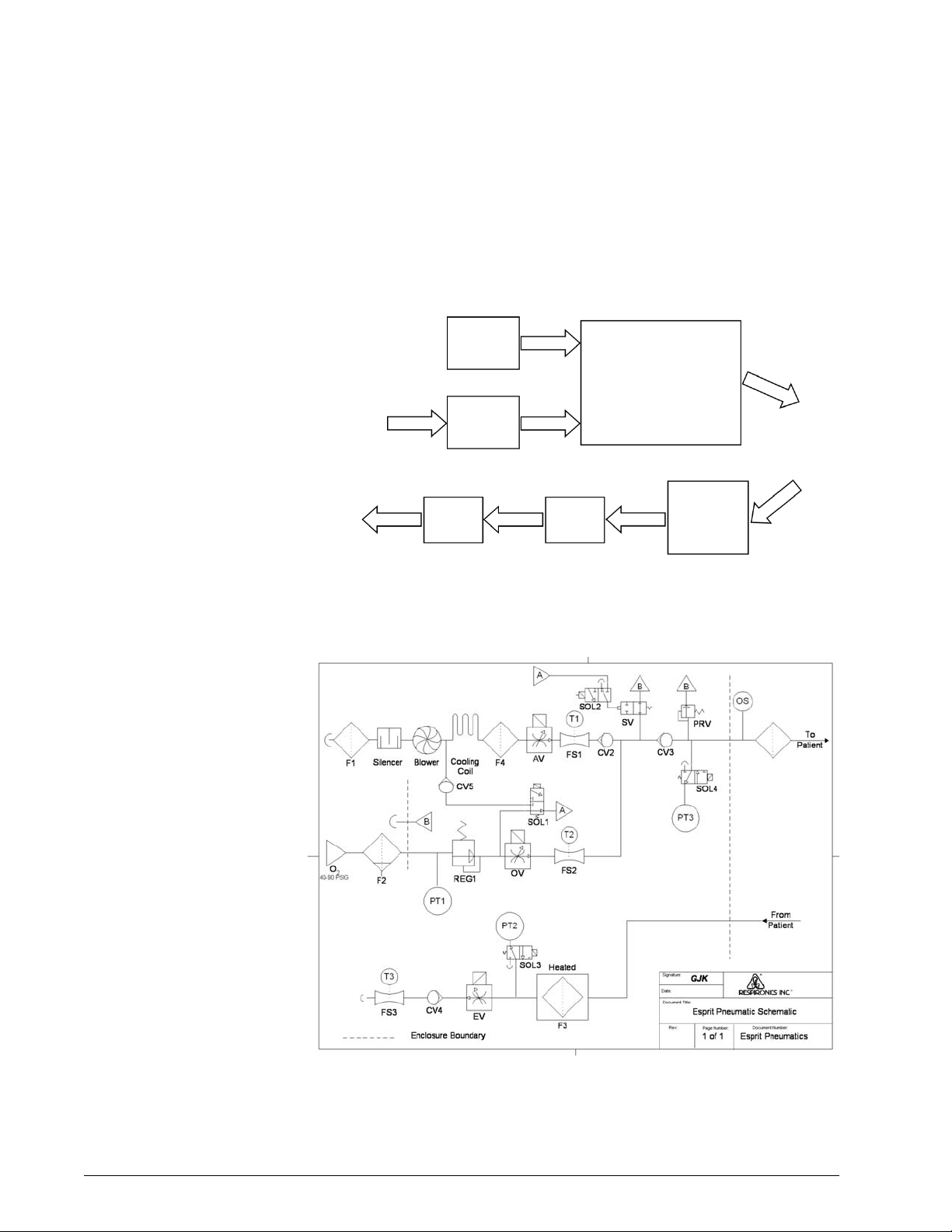
Pneumatic System The Esprit Ventilator pneumatic system consists of these subsystems (see
Figure 3-1):
• Internal blower (air source)
• Oxygen regulator (oxygen source)
• Inspiratory module
• Heated exhalation filter assembly
• Exhalation valve assembly
• Expiratory flow sensor
The internal blower generates the air pressure necessary for breath delivery,
eliminating the need for an external source of medical-grade compressed air.
An internal regulator regulates wall oxygen pressure. The ventilator mixes air
and oxygen in the inspiratory module before delivery to the patient.
Based on operator settings, the central processing unit (CPU) controls the air
valve, oxygen valve, and exhalation valve through stepper motor controller
printed circuit boards (PCBs). As flow is delivered to the patient, the air and
oxygen flow sensors and two pressure sensors provide feedback to the CPU.
The pressure relief and safety valves in the inspiratory module provide for
patient safety in the event of an over-pressure condition or any component or
system failure that could interfere with the patient’s ability to breathe when
connected to the ventilator.
REF 580-1000-02 G Esprit® Ventilator Service Manual © Respironics, Inc. 3-1
Page 16
Chapter 3
Theory of Operation
The exhalation filter conditions the exhaled gas, reducing the risk of
contamination or component damage due to bacteria or moisture in expired
gases. The exhalation filter is housed in a heated sleeve, which reduces the
relative moisture condensation in the exhalation filter, exhalation valve, and
expiratory flow sensor. Exhaled gas is then vented to atmosphere.
Air
O
2
Exhalation
Valve
Inspiratory Module
• Gas Mixing
• Pressure Relief Valve
• Safety Valve
To Patient
From Patient
Heated
Exhalation
Filter
Assembly
Oxygen
Supply
Room
Air
Blower
Oxygen
Regulator
Expiratory
Flow
Sensor
Figure 3-1: Pneumatic System Block Diagram
Figure 3-2 shows the Esprit ventilator pneumatic system and its components.
Figure 3-2: Pneumatic Schematic
3-2 Esprit® Ventilator Service Manual © Respironics, Inc. REF 580-1000-02 G
Page 17
Chapter 3
Theory of Operation
Delivery System The delivery system includes the components that condition and control the
flow delivered to the patient based upon operator-selected parameters. The
blower draws room air through the blower inlet filter (F1) and the muffler
(silencer) and outputs flow to the air valve assembly (AV). A pressure switch
(PS1) monitors oxygen input pressure. The oxygen water trap/inlet filter
assembly filters wall oxygen, and the oxygen regulator (REG1) regulates oxygen
down to 23 pounds per square inch, psi (1.5 kilopascals, kPa). Regulated
oxygen then enters the oxygen valve assembly (OV) and the crossover solenoid
(SOL1). The air and oxygen valves (AV and OV) are controlled by the
microprocessor, based on continuous feedback from the air and oxygen flow
sensors (FS1, T1 and FS2, T2).
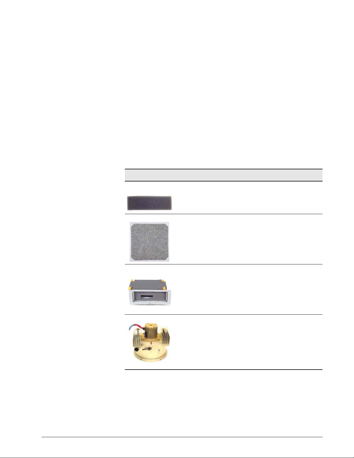
Delivery System Components
Blower Inlet Filter
(F1)
Cooling Fan Filter The cooling fan filter removes coarse particulate from ambient air
Muffler (Silencer) The muffler reduces the noise of air flow into the blower by channeling
Blower The blower draws room air though the air inlet filter and outputs the air
The blower inlet filter removes coarse particulate from ambient air as it
is entrained into the blower assembly. See section 4 for periodic
maintenance information.
entrained by the cooling fan. See section 4 for periodic maintenance
information
the air through a baffled system lined with sound absorbing material.
that is delivered to the patient and provides the pilot pressure that can
actuate the safety valve. The blower contains a DC motor and a series of
stator and impeller assemblies. It can provide at least 200 LPM of flow.
Blower speed is automatically adjusted to account for differences in gas
density due to altitude. The altitude can be adjusted from the hardware
screen in diagnostics mode. The High Pressure alarm limit setting also
affects blower speed.
REF 580-1000-02 G Esprit® Ventilator Service Manual © Respironics, Inc. 3-3
Page 18
Chapter 3
Theory of Operation
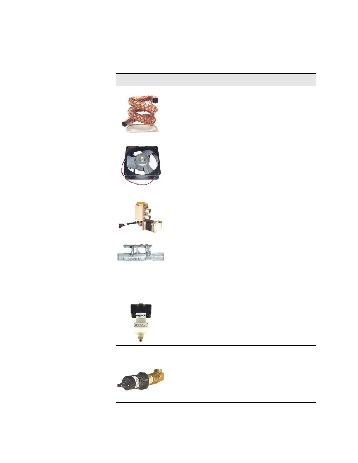
Delivery System Components
Cooling Coil The cooling coil is a copper tube connected to the outlet of the blower
Cooling Coil Fan The 24 V DC cooling coil fan removes the heat dissipated by the cooling
Air Valve Assembly
(AV)
Air Flow Sensor (FS1) The air flow sensor measures flow from the air valve. The ventilator uses
Oxygen Inlet
Connector (O
Oxygen Water Trap/
Inlet Filter Assembly
(F2)
)
2
that reduces the temperature of the gas from the blower before it
reaches the air valve.
coil and blower.
The air valve assembly contains a stepper motor that meters air flow
from the blower to achieve the target flow under CPU control, based on
operator selected parameters. It can deliver up to 200 LPM of flow.
this measurement to provide closed loop control of the air valve and to
compute the flow and volume delivered to the patient. A thermistor in
the flow sensor measures the temperature of the air and provides the
microprocessor with information to compensate the delivered flow.
The oxygen inlet connector provides a country-specific connection point
for an external oxygen gas supply of 40 to 90 psig (276 to 620 kPa).
The oxygen water trap/inlet filter assembly consists of a 5-micron (µ)
filter to remove particulate (both dry and liquid) from the oxygen gas
supply, a bowl with drain for accumulated water, and an oxygen inlet
connector.
Oxygen Supply
Pressure Switch (PS1)
The oxygen supply pressure switch is part of the oxygen regulator. PS1
is a normally open (NO) switch that closes when measured pressure is
greater than 40 psig (276 kPa), and provides a digital signal to the
sensor PCB indicating whether supply pressure is adequate at the
oxygen inlet.
PS1 opens if measured pressure is less than 35 psig (241.3 kPa). If the
oxygen supply pressure switch opens during normal ventilation (at O
21%), a Low O
Supply alarm results.
2
>
2
3-4 Esprit® Ventilator Service Manual © Respironics, Inc. REF 580-1000-02 G
Page 19
Delivery System Components
Chapter 3
Theory of Operation
Oxygen Regulator
(REG 1)
Oxygen Valve (OV) The oxygen valve assembly contains a stepper motor that meters flow
Oxygen Flow Sensor
(FS2)
Crossover Solenoid
(SOL1)
The oxygen regulator reduces the oxygen supply pressure to the proper
inlet pressure for the oxygen valve (22-24 psig, or 152-165 kPa @ 180
LPM) and supplies the regulated pressure to the crossover solenoid,
which pilots the safety valve.
from the oxygen regulator to achieve the target flow under CPU control,
based on operator-selected parameters. It can deliver up to 200 LPM of
flow.
The oxygen flow sensor measures the flow from the oxygen valve. The
ventilator uses this measurement to provide closed loop control of the
oxygen valve and to compute the flow and volume delivered to the
patient. A thermistor contained in the flow sensor measures the
temperature of the oxygen and provides temperature compensation
information to the microprocessor for delivered flow.
The crossover solenoid is a three-way valve that supplies either air or
oxygen pressure to pilot (hold) the safety valve closed during normal
ventilation. In its normal state, SOL1 is normally de-energized to pilot
the safety valve with oxygen. If oxygen pressure is lost, SOL1 is
energized and air (rather than oxygen) controls the safety valve.
Check Valve (CV5) The cross contamination check valve prevents the oxygen supply from
entering the air delivery system pneumatics (blower) in the event of a
crossover solenoid leak.
Inspiratory System The inspiratory system includes a manifold where air and oxygen are
blended and the inspiratory pressure transducer (PT3) is connected
through the inspiratory pressure transducer solenoid (SOL4). The
manifold also houses several components designed to ensure patient
safety, including the safety valve pilot solenoid (SOL2), safety valve
(SV), (CV2), inspiratory non-rebreathing check valve (CV3), pressure
relief valve (PRV), and oxygen sensor (OS).
Safety Valve Pilot
Solenoid (SOL2)
REF 580-1000-02 G Esprit® Ventilator Service Manual © Respironics, Inc. 3-5
The safety valve pilot solenoid directs the output of the crossover
solenoid to the safety valve or vents the pilot pressure line to
atmosphere.
During normal operation, SOL2 is energized and directs pressure from
the crossover solenoid to close the safety valve. During a high priority
alarm condition such as an occlusion or ventilator failure mode (VENT
INOP), SOL2 is deenergized to open the safety valve and allow the
patient to breathe room air.
Page 20
Chapter 3
Theory of Operation
Delivery System Components
Safety Valve (SV) The safety valve contains a spring-loaded diaphragm that is controlled
Air System Check
Valve (CV2)
Inspiratory Nonrebreathing Check
Valve (CV3)
Pressure Relief Valve
(PRV)
by safety valve pilot solenoid (SOL 2). Under normal conditions SV is
closed, allowing delivered flow to reach the patient. In the event of a
safety valve open (SVO) condition, pilot pressure is vented to
atmosphere, which opens SV and allows the patient to breathe room air
through the safety port at the rear of the ventilator.
The air system check valve (CV2) prevents oxygen from entering the air
delivery system in the event of a blower failure.
The inspiratory non-rebreathing check valve prevents the patient from
exhaling through the inspiratory limb during a safety valve open
condition, which prevents the patient from rebreathing exhaled gas.
The pressure relief valve provides a backup to the operator adjustable
high-pressure alarm and prevents excessive pressures in the patient
circuit. The PRV is spring-loaded to limit the maximum circuit pressure
to 130 to 140 cmH2O.
Oxygen Sensor (OS) The oxygen sensor is an optional device that can be installed between
Inspiratory Pressure
Transducer (PT3)
the 22-mm inspiratory port and the inspiratory bacteria filter. The
oxygen sensor is a galvanic device that measures the oxygen
concentration of the blended gas as it leaves the inspiratory manifold.
The output signal from the sensor is used for the high and low oxygen
concentration alarms. When the sensor is installed and calibrated, the
ventilator alarms if the measured oxygen concentration is not within 6%
of the %O
The inspiratory pressure transducer on the sensor PCB monitors system
pressure from the inspiratory side of the patient circuit during
exhalation pressure transducer autozeroing, ensuring uninterrupted
pressure monitoring. It is also used with the exhalation pressure
transducer to detect patient circuit occlusions.
setting.
2
3-6 Esprit® Ventilator Service Manual © Respironics, Inc. REF 580-1000-02 G
Page 21
Delivery System Components
Chapter 3
Theory of Operation
Inspiratory Pressure
Transducer Solenoid
(SOL4)
Exhalation System The exhalation system maintains circuit pressure and conditions, filters,
Heated Exhalation
Filter (F3)
Exhalation Pressure
Transducer (PT2)
Exhalation Pressure
Transducer Solenoid
(SOL3)
The inspiratory pressure transducer solenoid periodically vents the
inspiratory pressure transducer to atmosphere and makes a
measurement at zero (atmospheric) pressure. Periodically autozeroing
the transducer allows it to correct the slight zero voltage drift that can
occur over time, and improves the overall accuracy of the pressure
measurement.
During normal operation, SOL4 is de-energized and applies patient
circuit pressure to the inspiratory pressure transducer. During an
autozero, SOL4 is energized, venting the transducer to atmosphere.
This occurs during power on self test (POST), at the beginning of a
breath one minute after POST, six minutes after POST, eleven minutes
after POST, and hourly thereafter.
and monitors exhaled gas. It contains the heated exhalation filter (F3),
exhalation pressure transducer (PT2), exhalation pressure transducer
solenoid (SOL3), exhalation valve (EV), exhalation non-rebreathing
check valve (CV4), and the exhalation flow sensor (FS3).
The heated exhalation filter includes a heated filter sleeve and a
bacteria filter. The heater protects the exhalation flow sensor and
exhalation system components from condensation by heating exhaled
gas (which has cooled in the exhalation limb) above the dew point.
The exhalation bacteria filter protects the exhalation flow sensor and
exhalation system component from contaminants and filters exhaled
gas before it is vented to atmosphere.
The exhalation pressure transducer on the sensor PCB measures patient
circuit pressure from the exhalation side of the patient circuit. During
normal operation PT2 is the primary transducer for measuring patient
pressures, including peak inspiratory pressure (PIP), mean airway
pressure (MAP), end inspiratory pressure, and auto-PEEP. The
exhalation pressure transducer provides monitoring data for closed loop
control.
The exhalation pressure transducer solenoid periodically vents the
exhalation pressure transducer to atmosphere and makes a
measurement at zero (atmospheric) pressure. Periodically autozeroing
the transducer allows it to correct the slight zero voltage drift that can
occur over time, and improves the overall accuracy of the pressure
measurement.
During normal operation, SOL 3 is de-energized and applies patient
circuit pressure to the exhalation pressure transducer. During an
autozero, SOL3 is energized, venting the transducer to atmosphere.
This occurs during POST, at the beginning of a breath one minute after
POST, six minutes after POST, eleven minutes after POST, and hourly
thereafter.
REF 580-1000-02 G Esprit® Ventilator Service Manual © Respironics, Inc. 3-7
Page 22
Chapter 3
Theory of Operation
Delivery System Components
Exhalation Nonrebreathing Check
Valve (CV4)
Exhalation Valve (EV) The exhalation valve assembly is a stepper motor-controlled valve. At
Exhalation Flow
Sensor (FS3)
The exhalation non-rebreathing check valve prevents the patient from
inspiring room air through the exhalation limb of the patient circuit.
During normal operation, it blocks the exhalation system from
atmosphere, allowing the patient to trigger a breath.
the beginning of an inspiration, the exhalation valve shuts to create a
closed circuit and allow the patient system to pressurize. The exhalation
valve opens at the beginning of exhalation, allowing system pressure to
vent to atmosphere.
The exhalation valve also regulates positive end expiratory pressure
(PEEP) and expiratory positive airway pressure (EPAP) levels during
exhalation.
The exhalation flow sensor measures the flow leaving the ventilator. This
flow includes gas exhaled by the patient, tubing compliance volume,
and bias flow if flow triggering or Auto-Trak triggering is selected. The
ventilator uses the exhaled flow measurement to compute flow and
volume coming from the patient and the circuit.
A thermistor in the flow sensor measures the temperature of the gas and
provides the microprocessor with information to compensate the
measured flow.
3-8 Esprit® Ventilator Service Manual © Respironics, Inc. REF 580-1000-02 G
Page 23
Chapter 3
Theory of Operation
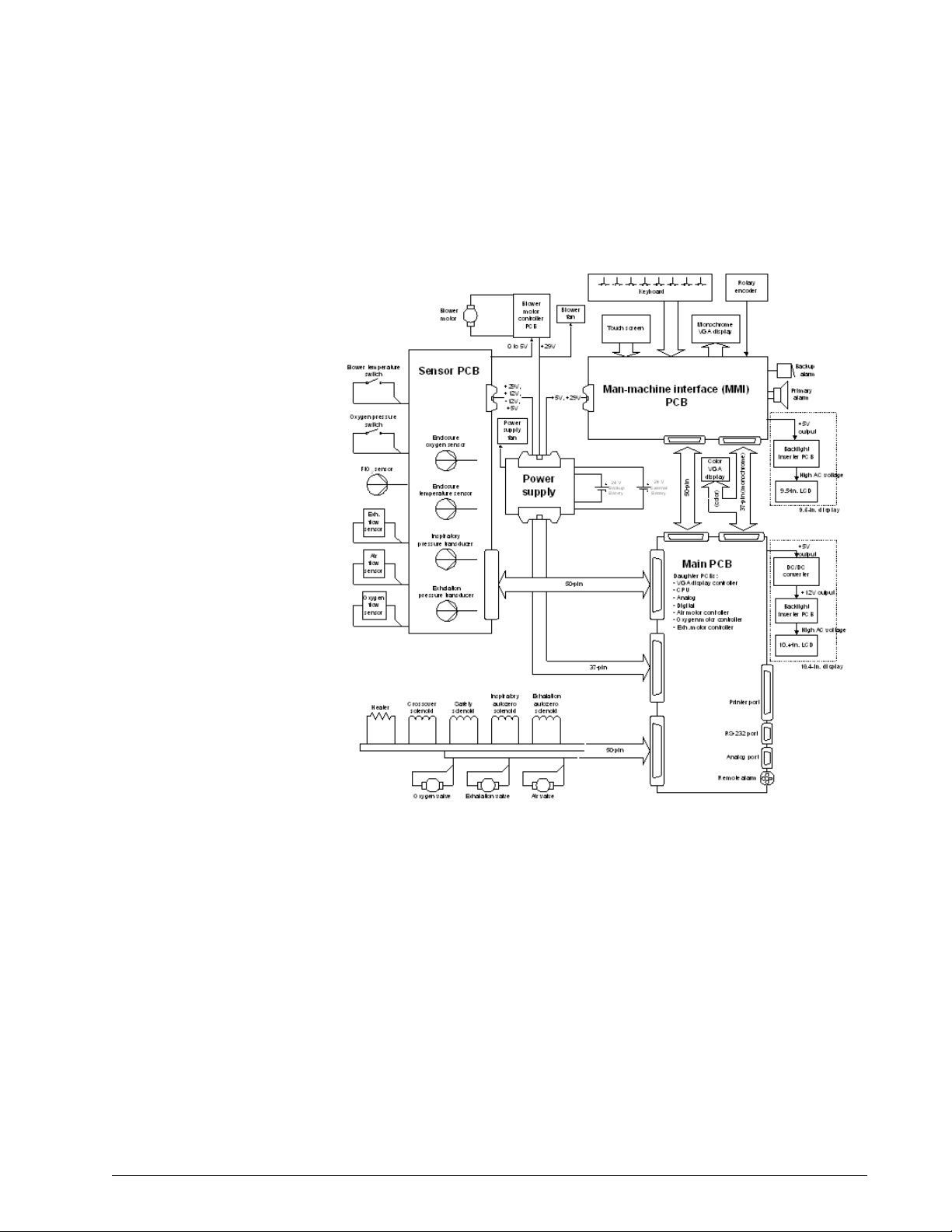
Ventilator System
Electronics
Figure 3-3 shows the electronic system. Schematics are available upon
request.
Figure 3-3: Electronic System Diagram
The ventilator can be powered by a 100 to 240 VAC 50/60 Hz or external 24 V
DC power sources (Backup Battery or External Battery). The power supply
conditions the input voltage and distributes +5 V, +12 V, -12 V, and +29 V to
the main PCB and blower motor controller to power digital electronics,
electropneumatic components, and displays. AC power to the humidifier port
can be used on 100-120 V units only.
The microprocessor on the CPU PCB and programs stored in memory control
the interaction of the pneumatic and electronic subsystems. Using inputs from
electropneumatic sensors and the operator, the CPU controls the flow,
pressure, and volume of air and oxygen to be delivered to the patient. The CPU
also monitors alarms and independently monitors software execution.
REF 580-1000-02 G Esprit® Ventilator Service Manual © Respironics, Inc. 3-9
Page 24

Chapter 3
Theory of Operation
The CPU interfaces with the pneumatics and displays through the main PCB
and daughter boards that are vertically mounted on the main PCB. The
daughter boards include the CPU PCB, digital PCB, analog PCB, VGA
controller PCB, and three stepper motor controller PCBs.
The digital control signals from the CPU are sent to the analog PCB where they
are converted into analog signals that control blower speed and chart recorder
outputs (pressure, flow, and volume). Analog data from the flow, pressure, and
oxygen sensors is conditioned and converted by the sensor PCB. The sensor
PCB conditions and coverts the data, and sends it to the analog PCB, where it
is read by the CPU.
Ventilator data from the CPU is conditioned by the VGA and man-machine
interface (MMI) PCBs, then displayed on an LCD.
The following table summarizes the electronic signal path for Esprit
components.
Component Signal Path Sequence
100% O2 indicator Front panel overlay, MMI PCB, main PCB, digital PCB, CPU
PCB
29 V Enable Main PCB, CPU PCB, power supply
Air (AV), oxygen (OV), exhalation
(EV) valves
Air (FS1), oxygen (FS2), exhalation
(FS3) flow sensors
Alarm High Indicator Front panel overlay, MMI PCB, main PCB, CPU PCB
Alarm Med/Low Indicator Front panel overlay, MMI PCB, main PCB, CPU PCB
Alarm Silence Indicator Front panel overlay, MMI PCB, main PCB, digital PCB, CPU
Backlight (9.5-in. display) Backlight inverter PCB, MMI PCB, backlight control
Backlight (10.4-in. display) Backlight inverter PCB, DC/DC converter PCB, main PCB,
Backup Alarm MMI PCB, main PCB, digital PCB, CPU PCB
Backup Battery, External Battery Power supply
Battery/Charging Indicator Front panel overlay, MMI PCB, power supply, main PCB,
Battery/In Use Indicator Front panel overlay, MMI PCB, main PCB, digital PCB, CPU
Battery/Low Indicator Front panel overlay, MMI PCB, digital PCB, CPU PCB
Blower DAC Blower controller PCB, sensor PCB, main PCB, analog PCB,
Blower on/off Blower controller PCB, sensor PCB, main PCB, CPU PCB
Blower temperature switch Sensor PCB, main PCB, digital PCB, CPU PCB
Console: all keys Front panel overlay, MMI PCB, main PCB, CPU PCB
Main PCB, motor controller PCB, CPU PCB
Sensor PCB, main PCB, analog PCB, CPU PCB
PCB
potentiometer.
backlight control potentiometer
CPU PCB
PCB
CPU PCB
3-10 Esprit® Ventilator Service Manual © Respironics, Inc. REF 580-1000-02 G
Page 25

Theory of Operation
Component Signal Path Sequence
Crossover solenoid (SOL1) Main PCB, CPU PCB
Enclosure temperature sensor Sensor PCB, main PCB, analog PCB, CPU PCB
Exhalation pressure transducer
(PT2)
Exhalation pressure transducer
solenoid (SOL3)
External Battery indicator Front panel overlay, MMI PCB, power supply
Heater Main PCB, CPU PCB
Inspiratory pressure transducer
(PT3)
Inspiratory pressure transducer
solenoid (SOL4)
Mains indicator Front panel overlay, MMI PCB, power supply
Non-maskable interrupt (NMI)
signal
Normal indicator Front panel overlay, MMI PCB, main PCB, CPU PCB
Oxygen Sensor (OS) Sensor PCB, main PCB, analog PCB, CPU PCB
Oxygen supply pressure switch
(PS1)
Primary Alarm MMI PCB, main PCB, digital PCB, CPU PCB
Primary alarm potentiometer MMI PCB
Printer Main PCB, CPU PCB
Remote alarm (nurse call) Main PCB, CPU PCB
Rotary encoder MMI PCB, main PCB, digital PCB, CPU PCB
Safety Valve indicator Front panel overlay, MMI PCB, main PCB, CPU PCB
Safety valve pilot solenoid (SOL2) Main PCB, CPU PCB
Screen Lock indicator Front panel overlay, MMI PCB, main PCB, CPU PCB
Touch screen MMI PCB, main PCB, digital PCB, CPU PCB
Vent Inop indicator Front panel overlay, MMI PCB, main PCB, CPU PCB
VGA backlight intensity
potentiometer (9.5-in. display)
VGA backlight intensity
potentiometer (10.4-in. display)
VGA display (9.5-in. display) MMI PCB, main PCB, VGA controller PCB, CPU PCB
VGA display (10.4-in. display) Main PCB, VGA controller PCB, CPU PCB
Sensor PCB, main PCB, analog PCB, CPU PCB
Main PCB, CPU PCB
Sensor PCB, main PCB, analog PCB, CPU PCB
Main PCB, CPU PCB
Sensor PCB, main PCB, CPU PCB
Sensor PCB, main PCB, digital PCB, CPU PCB
MMI PCB, backlight inverter PCB
Backlight inverter PCB
Chapter 3
REF 580-1000-02 G Esprit® Ventilator Service Manual © Respironics, Inc. 3-11
Page 26
Chapter 3
Theory of Operation
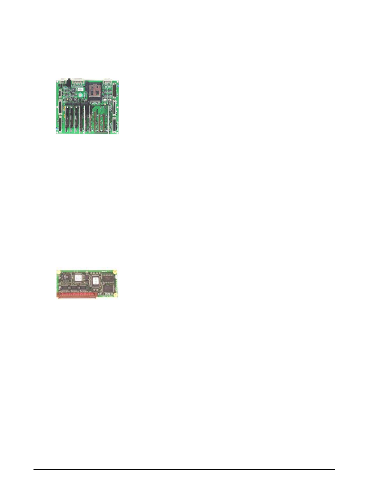
Main PCB
The CPU and other ventilator logic interact through the system data, address,
and control buses on the main PCB. The main PCB receives input signals from
various keys on the console or touch screen display and sends them to the
CPU. The main PCB also contains signal inputs for non-maskable interrupt,
running on AC, and running on external battery.
The main PCB receives control signals from the CPU and outputs them to
various pneumatic components and console indicators. The main PCB receives
signals from the digital PCB to turn on the indicators for alarm silence, 100%
oxygen, AC power, external battery power, and backup battery status. The main
PCB receives signal from the CPU PCB to turn on the backup alarm, enable
24V, and the Screen Lock, Battery/Charging, and Vent Inop indicators. The
CPU PCB reads the Accept key from the main PCB.
The main PCB includes a normal open and normal closed relay that can trigger
the remote nurse call alarm. Interface connectors on the main PCB include the
RS-232, parallel printer, analog output, and remote alarm connectors.
Other signals routed by the main PCB are the reset, MMI PCB reset, sensor
PCB reset, primary alarm, primary alarm failure detection logic, backup alarm,
remote alarm, printer, POST timer, clocked serial interface (CSI) signals, and
the battery backed +3.6 V.
CPU PCB
The CPU PCB contains the microprocessor, memory, I/O ports, and associated
control circuitry that controls the ventilator. Functional circuits contained on
the CPU PCB include:
• V851 microprocessor with a 25-Mhz clock.
• Static RAM that stores ventilator data.
• EEPROM that stores patient settings.
• Flash memory that contains ventilator operating software.
• One time programmable (OTP) memory that stores the POST routine.
• Internal RS-232 port that receives ventilator data from the touch
screen.
• Non-maskable interrupt that tells the CPU a power source has been
lost or interrupted.
• 5-msec bus timer that monitors hardware operation.
• 169-msec watchdog timer that monitors software operation.
• Data address and control bus to the main PCB.
• Current version includes 2 MB memory capacity (previous versions
included 1 and 1.5, MB).
3-12 Esprit® Ventilator Service Manual © Respironics, Inc. REF 580-1000-02 G
Page 27
Chapter 3
Theory of Operation
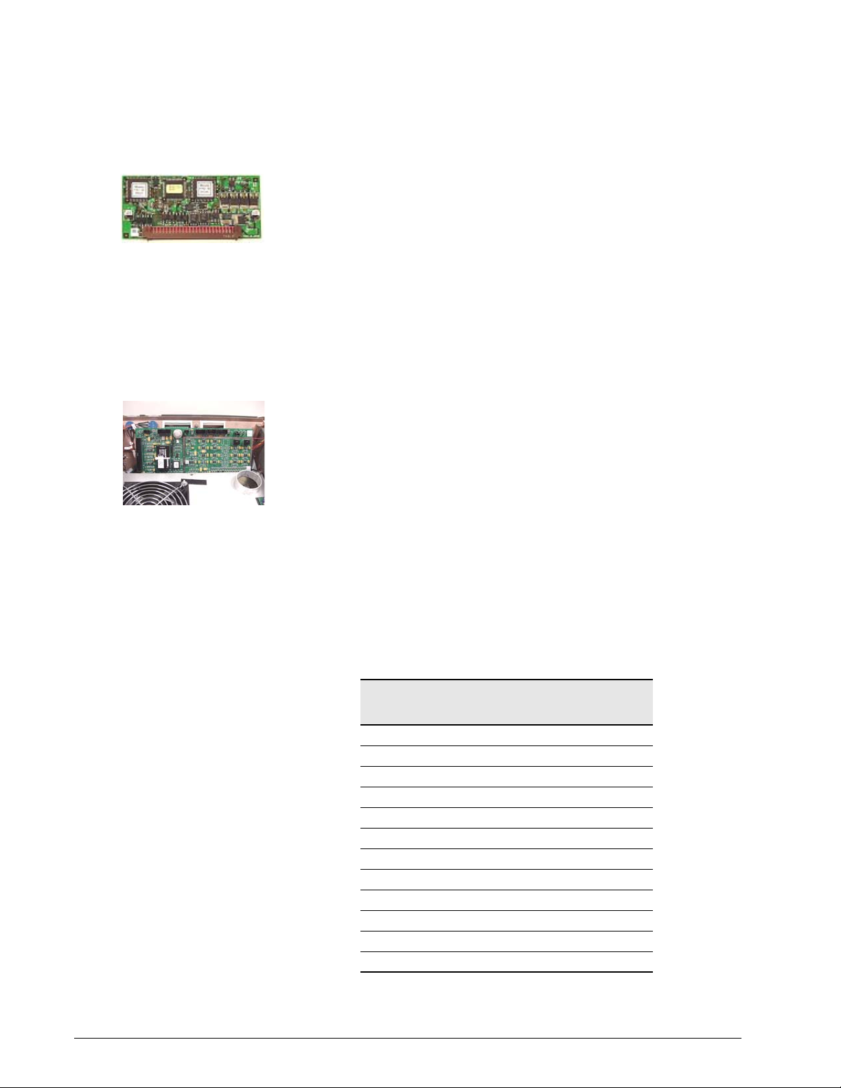
Analog PCB
The analog PCB performs a digital-to-analog conversion of signals from the
CPU to the blower controller PCB and analog output port. The analog PCB
connects directly to the system bus on the main PCB, and includes these
functional circuits:
• An eight-bit digital to analog converter (DAC) that converts digital
signals from the CPU to analog for the blower and external devices
such as chart recorders and bedside monitors.
• Clocked serial interface (CSI), a high-speed communication link
between the air, oxygen, and exhalation motor controllers and flow
sensor lookup tables contained on the CPU and the voltage monitor
register.
• A circuit that retrieves converted data from the sensor PCB.
Digital PCB
The digital PCB conditions serial port signals coming from and going to the
CPU PCB. It also contains control circuitry for the power fail alarm, primary
alarm, backup alarm, RS-232 port, and rotary encoder.
Digital inputs include analog-to-digital converter (ADC) out of range,
compressor temperature switch, and oxygen present. Digital outputs include
the alarm silence indicator, 100% oxygen indicator, running on AC indicator,
running on external battery indicator, backup battery status indicators, printer
ready signal, and printer direction.
VGA Controller PCB
The VGA controller PCB contains the date and real time clock and LCD VGA
display controller drivers.
Blower Controller PCB
The blower motor controller PCB controls the speed of the blower motor based
on analog input conditioned by the sensor PCB. It includes a lockup sensing
circuit, which monitors sensors in the blower motor to detect a locked rotor
condition. If the blower motor stops running, the lockup sensing circuit shuts
off power to the blower.
REF 580-1000-02 G Esprit® Ventilator Service Manual © Respironics, Inc. 3-13
Page 28
Chapter 3
Theory of Operation
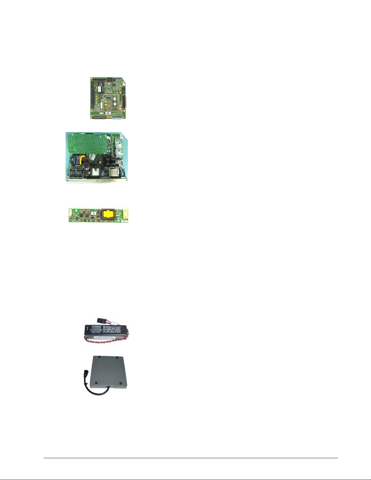
Motor Controller PCBs
There are three motor controller PCBs for the air valve, oxygen valve, and
exhalation valve. The three boards are physically the same, and are
differentiated by the slot they occupy on the main PCB:
• Exhalation valve motor controller PCB: slot CN11
• Oxygen valve motor controller PCB: slot CN12
• Air valve motor controller PCB: slot CN13
Each motor controller PCB includes a microprocessor dedicated to controlling
the corresponding motor, and drives the step positions of the motor based on
input from the CPU.
Sensor PCB
The sensor PCB contains an analog to digital converter (ADC) that converts
analog signals from various pneumatic components and the power supply into
digital signals for the CPU. Signals include: air flow and temperature, oxygen
flow and temperature, exhalation flow and temperature, inspiratory and
exhalation pressure, battery voltage, FIO
enclosure oxygen concentration.
2, enclosure temperature, and
The sensor PCB conditions blower speed analog input and the on/off control to
the blower controller PCB, and routes signals for the oxygen pressure and
blower temperature switches.
The sensor PCB also includes voltage monitors. LEDs on the sensor PCB light
to indicate under- and over-voltage conditions, as summarized in Table 3-2.
LED on Sensor
PCB
D3 Power supply: -12 V under
D4 Power supply: +12 V under
D5 Power supply: +24 V under
D6 Sensor PCB: +5 V under
D7 Sensor PCB: +5 V over
D8 MMI PCB: +5 V under
D9 MMI PCB: +5 V over
D10 Power supply: +10 V under
D11 Power supply: +10 V over
D12 Main PCB: +5 V over
D13 Main PCB: +5 V under
D49 Power fail
Voltage Condition
3-14 Esprit® Ventilator Service Manual © Respironics, Inc. REF 580-1000-02 G
Page 29
Chapter 3
Theory of Operation
Man-Machine Interface (MMI) PCB
The MMI PCB interfaces the front panel overlay, VGA display, rotary encoder,
and touch screen to the CPU via the main PCB. The MMI PCB contains control
circuitry for the primary and back-up alarms, and includes the hard keys and
LEDs on the front panel membrane keypad.
Power Supply
The power supply converts AC voltage to DC voltage to be used by the system
electronics. The switching power supply can accept voltage from 100 to 240 V
AC (50/60 Hz), and converts it to +5 V, + 12 V, and +29 V DC voltages. In the
absence of AC voltage, the power supply converts the +24V DC input voltage
from an external DC power source (Backup Battery or External Battery). The
power supply also includes power fail logic and charging circuitry for the
backup battery.
Backlight Inverter PCB
For 9.5-in. displays: the backlight inverter PCB converts 5 V to approximately
500 V to drive the backlight on the VGA display assembly.
For original 10.4-in. displays: the backlight inverter PCB converts 12 V to
approximately 500 V to drive the backlight on the VGA display assembly.
For 2nd generation 10.4-in. displays: the backlight inverter PCB converts 5V
to approximately 500V to drive the backlight on the VGA display assembly.
WARNING: The backlight inverter PCB generates high voltage. To avoid personal injury,
verify that the AC and external DC power sources (Backup Battery or External
Battery) are disconnected from the ventilator.
Real-Time Clock Battery
The real time clock battery is a 3.6-V lithium battery that supplies power to the
real time clock on the VGA controller PCB when ventilator power is off.
Backup Battery
The optional Backup Battery can power the ventilator for approximately 30
minutes under nominal settings if AC power is lost.
REF 580-1000-02 G Esprit® Ventilator Service Manual © Respironics, Inc. 3-15
Page 30
Chapter 3
Theory of Operation
External Battery
The optional External Battery supplements the Backup Battery, and can
provide an additional two hours of ventilator operation (depending on ventilator
settings). The ventilator runs on AC power when available, then External
Battery power if installed, and then switches to Backup Battery power when
External Battery power is depleted.
DC/DC Converter PCB (use with original 10.4-in. displays only)
The DC/DC converter PCB converts a 5-V input to a 12-V output for the
backlight inverter PCB on 10.4-in. displays.
Optical Rotary Encoder
The knob on the user interface is an optical rotary encoder. It converts a
mechanical position into a representative electrical signal using a patterned
disk or scale, a light source, and photosensitive elements.
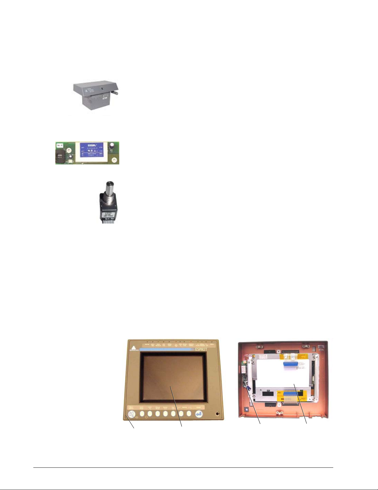
Graphic User Interface (GUI)
Esprit ventilators include a 9.5-in. monochrome or 10.4-in. color-capable
liquid crystal display (LCD) screen. The 9.5-in. LCD is a monochrome 640 x
480 active matrix display. The 10.4-in LCD is a color 640 x 480 active matrix
display capable of operating in monochrome or color mode. The 10.4-in. GUI
has mounting screws at the bottom corners, while the 9.5-in. GUI does not.
The GUI includes an infrared (IR) touchframe that contains 24 vertical and 32
horizontal IR emitter detector pairs, each of which is sequenced at a high
frequency. When the screen is touched, breaking the IR beam, the x and y
coordinates that correspond to the position on the screen are communicated to
the microprocessor.
Overlay assembly
IR touchframe
Backlight inverter
PCB
10.4-in. LCD
display
3-16 Esprit® Ventilator Service Manual © Respironics, Inc. REF 580-1000-02 G
Page 31

Chapter 3
Theory of Operation
Remote Alarm (Nurse Call)
Esprit remote alarm contacts provide remote alarm capability, allowing the
ventilator to annunciate an active medium or high priority alarm at a location
away from the ventilator. Pressing Alarm silence mutes the remote alarm.
The ventilator signals an alarm condition using normally open (NO) or normally
closed (NC) relay contacts, where the deenergized state indicates an active
alarm. The remote alarm port is a standard ¼-in. phone jack (ring, tip, sleeve)
connector (Figure 3-4).
• When the ring and sleeve are used, the relay is open during normal
ventilator operation and closed when an alarm is active or the
ventilator is off.
• When the tip and sleeve are used, the relay is closed during normal
operation and open when an alarm is active or the ventilator is off.
CAUTION: The remote alarm port is intended to connect only to SELV (safety
extra low voltage and ungrounded system with basic insulation to
ground), in accordance with IEC60601-1. To prevent damage to
the remote alarm, the signal input should not exceed the
maximum rating
of 24 VAC or 36 VDC at 500mA with a current of 1mA.
Remote alarm
connector and cable
NO
NC
Common
Figure 3-4: Remote Alarm (Nurse Call) Connector
Ring
Tip
Sleeve
For ventilators equipped with software revision 4.20 or later, the 15-pin analog
output (chart recorder) port of the ventilator can also be used to connect to the
Respironics Lifecare remote alarm system. The Lifecare remote alarm sounds
under these conditions:
• A high or medium priority alarm condition is active.
• Ventilator power is turned off or disconnected.
• The Respironics Lifecare remote alarm system is disconnected from
the ventilator.
• The ventilator runs POST.
NOTE: To connect the Lifecare remote alarm system to an Esprit ventilator, a
DB15 to BNC cable adapter must be installed into the analog output port.
REF 580-1000-02 G Esprit® Ventilator Service Manual © Respironics, Inc. 3-17
Page 32

Chapter 3
Theory of Operation
(This page is intentionally blank.)
3-18 Esprit® Ventilator Service Manual © Respironics, Inc. REF 580-1000-02 G
Page 33

Chapter 4. Periodic Maintenance
Perform cleaning, sterilizing, and periodic maintenance procedures to ensure
consistent ventilator operation. Hospital personnel can perform all
maintenance tasks except the annual and 12,500-hour preventive
maintenance procedures (the preventive maintenance procedures must be
performed by a qualified service technician). The Esprit Ventilator Operator’s
Manual summarizes periodic care and maintenance procedures. Table 4-1
shows the periodic maintenance schedule.
Schedule for Periodic Maintenance
Frequency Component Maintenance
During ventilator
setup
At least daily, and as
recommended by
filter manufacturers
• Inspiratory bacteria filter
• Ventilator and patient circuit
components
• Inspiratory and expiratory filters
• Inspiratory and expiratory filters • Monitor performance of filters and
CAUTION: Do not operate the Esprit Ventilator without a properly functioning
expiratory filter and heater. Doing so may cause damage to delicate ventilator
components, such as the expiratory flow sensor, which may lead to inaccurate
spirometry or a Vent Inop condition.
WARNING: Vent Inop is a serious condition which is indicated by both visual and
audible alarms. If the ventilator is attached to a patient when Vent Inop occurs, the
patient must be supported with another means of life support ventilation.
• Check filter for occlusions, cracks and
tears.
• Perform SST (Short Self-Test)
whenever circuit components are
changed
• Perform EST (Extended Self-Test)
between patient uses
• Ensure that the ventilator functions
normally with both filters in place
replace as needed. Review ventilator
patient graphics frequently for changes
in expiratory resistance which may
indicate degradation of expiratory filter.
• Follow filter manufacturer
recommendations regarding duration
of use, maintenance (for reusable
filters), removal and disposal. Note
that high humidity and aerosol
medications may reduce expiratory
filter life, increase expiratory
resistance, and/or cause filter damage.
At least daily • Oxygen supply water trap and
filter
REF 580-1000-02 G Esprit® Ventilator Service Manual © Respironics, Inc. 4-1
• Check and empty as required every
shift
Page 34

Chapter 4
Periodic Maintenance
At least every 250
hours
Annually • Annual preventive
12,500 hours • 12,500 hour preventive
As required • External oxygen sensor
• Air Inlet & Fan Filters • Inspect and clean. Some
maintenance kit (P/N
1034840). Kit contents are
subject to change.
CAUTION: The annual preventive maintenance procedure is to be performed only
by a qualified service technician
maintenance kit (P/N
1001733). Kit contents are
subject to change.
CAUTION: The 12,500 hour preventive maintenance procedure is to be
performed only by a qualified service technician.
• Backup Battery
Table 4-1: Schedule for Periodic Maintenance
environments cause a quicker
collection of lint and dust than others,
requiring maintenance more frequently
than every 250 hours.
• Install annual preventive maintenance
kit.
• Clean ventilator interior and exterior
• Complete performance verification
procedure
• Install 12,500 hour preventive
maintenance kit
• Clean ventilator interior and exterior
• Complete performance verification
procedure
• Replace and recalibrate new sensor by
running Extended Self-Test
• If you have the backup battery option,
refer to section 13 of the Operator’s
Manual for charging and maintenance
instructions
4-2 Esprit® Ventilator Service Manual © Respironics, Inc. REF 580-1000-02 G
Page 35

Chapter 5. Repair
This section describes the Esprit Ventilator’s diagnostic mode and other repair
procedures. Diagnostic mode allows you to:
• Run short self test (SST).
• Run an extended self test (EST).
• Check the software revision of the ventilator and installed options.
• Change the time and date.
• Enable or disable the automatic patient circuit compliance feature.
• Set the proper altitude.
• Check diagnostic codes.
• Control and monitor pneumatic components and voltages for
troubleshooting.
• Check bacteria filter resistance.
The diagnostic mode includes hardware diagnostics that facilitate
troubleshooting in the event of an SST failure, an EST failure, or a
performance verification failure.
WARNING: Diagnostic mode suspends normal ventilation: disconnect the patient from the
ventilator before entering diagnostic mode.
CAUTION: Troubleshooting and repair should be performed only by a qualified
service technician. Respironics Esprit Factory Service Training is highly
recommended prior to performing service procedures on the Esprit
Ventilator. Contact Customer Service at 1-800-345-6443 or 724-3874000 for more information.
REF 580-1000-02 G Esprit® Ventilator Service Manual © Respironics, Inc. 5-1
Page 36

Chapter 5
Repair
Entering Diagnostic
Mode
To start Esprit ventilator diagnostics, simultaneously press the ALARM RESET
and 100% O
turning ventilator power on. At the prompt, touch OK to enter diagnostic mode
(Figure 5-1).
2 keys on the front panel for approximately five seconds while
Figure 5-1: Entering Diagnostic Mode
User Configuration The user configuration screen (Figure 5-2) allows you to:
• Change the date and time.
• Enable or disable the automatic patient circuit compliance
compensation feature.
• Set the proper altitude.
To view the user configuration screen, touch User Config on the diagnostic
screen.
Figure 5-2: User Configuration Screen
5-2 Esprit® Ventilator Service Manual © Respironics, Inc. REF 580-1000-02 G
Page 37

Chapter 5
Repair
Changing the Date and Time
Follow these steps:
1. Touch the button for the value you want to change.
2. Touch the Increase or Decrease bar or turn the knob to adjust the
value.
3. Press Accept (onscreen button or offscreen key) to confirm the
change.
4. Touch Apply Date or Apply Time to apply the change (changes do not
take effect until you touch the button).
Setting the Time Format
Touch 24hr Clock to toggle between standard 12-hour and 24-hour time
format. The lower right corner of the diagnostic screen shows the selected
format.
Altitude
A correct altitude setting allows the ventilator to deliver tidal volumes at
optimal accuracy. Follow these steps to set the altitude:
1. Verify the altitude using an altimeter if available, or estimate altitude
in feet or meters above sea level.
2. Touch Altitude.
3. Touch the Increase or Decrease bar or turn the knob to adjust the
value.
4. Press Accept.
WARNING: Reenter the appropriate altitude setting whenever upgrading software. The
altitude setting reverts to the default setting (9999 feet, displayed as ----) at
every software upgrade.
Compliance Enable
The ventilator can use compliance correction to compensate for volume loss in
the patient breathing circuit due to the compressible volume of the tubing.
Touch Compliance to enable or disable compliance correction:
• Enabling compliance correction means that the tubing compliance
volume measured during SST or EST will be added to delivered
volume. Enabling compliance correction improves the accuracy of
volume delivery during normal operation.
• Disabling compliance correction means that tubing compliance
volume is not added to delivered volumes. Compliance correction is
typically disabled during performance testing.
REF 580-1000-02 G Esprit® Ventilator Service Manual © Respironics, Inc. 5-3
Page 38

Chapter 5
Repair
• After downloading software, disable compliance correction, then reenable compliance correction (even though compliance correction
appears enabled).
Backup Battery/
Confirmation
If the backup battery is installed, the operator can have the Esprit confirm the
backup battery is connected each time that the machine powers on. Pressing
the BKUP BATTERY button (Figure 5-3) allows this confirmation feature,
identified by an active button with a white background.
Backup Battery
(confirm at
startup)
button active
Figure 5-3: Backup Battery Activated
From then on when the machine powers on it searches for a backup battery. If
the backup battery is connected to the ventilator the startup is normal. If the
backup battery is not connected then the ventilator displays a message at
startup and a 5002 Diagnostic Code will be logged.
Figure 5-4: No Backup Battery Connected message
Short Self Test (SST) SST verifies the integrity of the patient circuit tubing by measuring its leak
rate and compliance. SST also tests some hardware, including the safety valve
(SV), flow sensor tables, autozero solenoids and the inspiratory nonrebreathing check valve (CV3). Perform SST after every patient circuit change.
WARNING: Do not use a ventilator that has failed SST without verifying operational
readiness by other means. Doing so may place a patient at risk.
5-4 Esprit® Ventilator Service Manual © Respironics, Inc. REF 580-1000-02 G
Page 39

Chapter 5
Repair
WARNING: Never initiate an SST while the patient is connected to the ventilator. The high
airway pressures generated during SST can injure a patient.
Required equipment: the intended patient circuit assembly and a rubber cork.
Follow these steps to run SST:
1. Connect the intended patient circuit to the ventilator.
2. Touch SST on the diagnostic screen (Figure 5-5).
3. Touch Start SST to begin the test.
4. When prompted, unblock the wye and touch OK.
5. When prompted, block the wye and touch OK.
6. When SST is completed successfully, touch OK. The SST screen
shows the results of each test. Diagnostic code 2000 indicates that
SST was successfully completed.
If any SST tests fail, the screen displays failure data, including diagnostic
code, measured value, and passing values.
• Touch RETEST to repeat the test.
• Touch CONTINUE to skip the failed test.
• Touch CANCEL to exit EST.
Figure 5-5: Starting SST
REF 580-1000-02 G Esprit® Ventilator Service Manual © Respironics, Inc. 5-5
Page 40

Chapter 5
Repair
Extended Self Test
(EST)
EST verifies the functional integrity of the ventilator by testing its hardware
subsystems and components. Perform EST between patients, during
preventive maintenance, performance verification, for oxygen sensor
calibration, or if ventilator operation is questionable.
WARNING: Do not use a ventilator that has failed EST without verifying operational
readiness by other means. Doing so may place a patient at risk.
WARNING: Never initiate an EST while the patient is connected to the ventilator. The high
airway pressures and gas flows generated during EST can injure a patient.
EST requires this equipment:
• Reusable adult patient circuit assembly.
• Rubber cork.
• Regulated oxygen source.
• Optional: an external oxygen sensor to perform the automatic oxygen
sensor test and calibration.
• Optional: a remote alarm.
Follow these steps to run EST:
NOTE: Steps 10 & 11 are not performed when Neo is selected.
1. Verify that the bacteria filters and oxygen sensor are connected to the
ventilator.
2. Connect the patient circuit to the ventilator.
3. Touch EST on the diagnostic screen (Figure 5-6).
4. Touch Start EST to begin the test.
Figure 5-6: Starting EST
5-6 Esprit® Ventilator Service Manual © Respironics, Inc. REF 580-1000-02 G
Page 41

Chapter 5
Repair
5. When prompted, unblock the wye and touch OK.
6. When prompted, block the wye with the cork and touch OK.
7. When prompted, connect the oxygen source to the ventilator and touch
OK. (This prompt does not appear if the ventilator is already
connected to an oxygen source.)
8. When prompted, disconnect the oxygen source from the ventilator and
touch OK.
9. When prompted, reconnect the oxygen source to the ventilator and
touch OK.
10. When prompted, disconnect the patient circuit from the heated
exhalation filter and touch OK.
11. When prompted, reconnect the patient circuit to the heated filter and
touch OK.
12. At the message, Is the primary audio alarm active? touch the YES key
if the alarm is sounding, or NO if it is not.
13. At the message, Is the backup audio alarm active? touch YES if the
alarm is sounding, or NO if it is not.
14. At the message, Is the remote alarm connected? touch YES if it is, or
NO if it is not.
15. At the message, Is the remote alarm active? touch YES if the alarm is
sounding, or NO if it is not.
16. Observe LEDs and press YES or NO as prompted to indicate whether
they light.
17. Press the front panel keys as prompted.
18. When EST is completed successfully, touch OK. The EST screen
shows the results of each test. Diagnostic code 3000 appears in the
diagnostic log each time EST is successfully completed.
If any EST tests fail, the screen displays failure data, including diagnostic
code, measured value, and passing values.
• Touch RETEST to repeat the test.
• Touch CONTINUE to skip the failed test.
• Touch CANCEL to exit EST.
REF 580-1000-02 G Esprit® Ventilator Service Manual © Respironics, Inc. 5-7
Page 42

Chapter 5
Repair
Software Screen To view the software screen, touch Software on the diagnostic screen (Figure
5-7). The software screen shows the:
• Ventilator serial number.
• Part number and version of the flash and one time programmable
(OTP) software.
• Version of the air stepper valve, oxygen stepper valve, exhalation
stepper valve, and display.
• Air, oxygen, and exhalation flow sensor part numbers.
• Options installed, if any.
Figure 5-7: Diagnostic Mode Software Screen
Diagnostic Codes The Esprit Ventilator generates diagnostic codes when the microprocessor
detects a fault during normal operation, or if a failure occurs during SST or
EST. Section 6 lists diagnostic codes, and recommended repair procedures for
each code.
5-8 Esprit® Ventilator Service Manual © Respironics, Inc. REF 580-1000-02 G
Page 43

Chapter 5
Repair
To view the diagnostic code screen, touch Diag. Codes on the diagnostic screen
(Figure 5-8).
Figure 5-8: Diagnostic Code Screen
The diagnostic code screen displays the following information:
1. Number: Diagnostic codes are numbered in reverse order of
occurrence, with the most recent code first.
2. Code: The number assigned to a specific failure, which can help
determine the cause of a failure.
The first digit of the four-digit diagnostic codes indicates the type of fault:
1xxx: Failure during power on self test (POST).
2xxx: Failure during short self test (SST).
3xxx: Failure during extended self test (EST).
4xxx: Continuous built-in test failure (failures during normal ventilation).
5xxx: Safety valve open/Backup battery not connected.
6xxx: Not used.
7xxx: Power supply failure.
8xxx: Software diagnostic information.
9xxx: Sensor/internal communication fault.
REF 580-1000-02 G Esprit® Ventilator Service Manual © Respironics, Inc. 5-9
Page 44

Chapter 5
Repair
3. Repeat: If the same code occurs consecutively, the repeat column is
incremented (rather than displaying the code again). For example, if
code 1002 occurs three consecutive times, it is logged as code 1002
with ì2î in the repeat column. The repeat column increments (up to a
maximum of 255) until a different code occurs.
4. Tim e : Diagnostic codes are time-stamped in hour/minute/second
format (for example, 09:15:23). The time is that of the most recent
occurrence of the code.
5. Date: Diagnostic codes are date-stamped in a month/day/year format
(for example, 09/12/01) to indicate the most recent occurrence of the
code.
6. Corrupted: The microprocessor regularly cross checks the data in
memory. If it determines that the diagnostic code in memory has been
corrupted, a Ye s entry indicates that its validity is suspect.
7. Next Pg and Prev Pg buttons: The ventilator can log up to 20 error
codes but can only display 10 on a screen. Touch the Next Pg button
to view the next group of codes, or Prev Pg to view the previous group.
8. Clear Codes button: Allows you to delete diagnostic codes.
NOTE: Diagnostic codes are the primary means of fault diagnosis and should
only be deleted by a qualified service technician.
To delete diagnostic codes, touch Clear Codes. At this message:
Are you sure you want to clear the codes?
Touch YES to clear the codes or NO to retain the codes.
Hardware Diagnostics The hardware screen (Figure 5-9) verifies the operational integrity of
components in case of a failure during SST, EST, or performance verification.
The hardware diagnostics screen allows you to:
• Set specific air and oxygen valve flow rates and step positions.
• Incrementally open and close the exhalation valve.
• Set various analog and digital voltages.
• Control power to the blower, filter heater, and 24-V components.
• Exercise the solenoids.
• View hardware status.
5-10 Esprit® Ventilator Service Manual © Respironics, Inc. REF 580-1000-02 G
Page 45

Chapter 5
Repair
NOTE: On the hardware screen, a white background indicates that the button is
enabled or energized, and a gray background indicates that a button is
disabled or de-energized.
Figure 5-9: Diagnostic Mode Hardware Screen
Flow Control Hardware
• The Air button controls the flow rate of the air controller, and allows
you to set an air flow from 0 to 200 LPM or step position from 0 to
2000 steps.
• The Oxygen button controls the flow rate of the oxygen controller, and
allows you to set an oxygen flow from 0 to 200 LPM or step position
from 0 to 2000 steps.
• The Exhalation button controls the steps of the exhalation valve, and
allows you to open or close the exhalation valve from 0 (fully open) to
2000 (fully closed) steps. (Although the exhalation stepper motor can
be commanded to 2000 steps, a maximum of 1800 steps is
displayed.)
Voltage Control Hardware
• The Monitors button simulates voltages for pressure, volume, and flow
analog output voltages. The selected voltage (from 0 to 5 V) is sent to
the analog output port (the DB15 connector on the ventilator back
panel).
• The Voltage Wrap button allows you to adjust the blower DAC voltage
from 0 to 5 V, and compare it to the ADC output voltage shown in the
Voltage Wrap status display.
• The Blower button allows you to adjust blower voltage from 0 to 5 V.
REF 580-1000-02 G Esprit® Ventilator Service Manual © Respironics, Inc. 5-11
Page 46

Chapter 5
Repair
On/Off Hardware
• The Blower button turns the blower on and off.
• The Filter Heat button turns the filter heater on and off.
• The 24V Power button turns all pneumatic components on and off
simultaneously without disturbing the display.
Solenoid Hardware
• The Inhalation button toggles SOL4 between circuit pressure and
atmospheric pressure.
• The Safety button opens and closes SOL2, which controls the source
pressure that opens or closes the safety valve.
• The Exhalation button toggles SOL3 between circuit pressure and
atmospheric pressure.
• The Crossover button toggles SOL1, which determines which gas
provides source pressure to SOL2. SOL1 uses air to provide source
pressure to SOL2 when energized, and uses oxygen when deenergized.
Status Displays
The displays on the right side of the hardware screen provide real time
feedback on various flows, step positions, pressures, voltages, and
temperatures measured by the internal flow, pressure, voltage, and
temperature sensors.
• Air Flow displays the measured flow passing through the air flow
sensor.
• Oxygen Flow displays the measured flow passing through the oxygen
flow sensor.
• Exhalation Flow displays the measured flow passing through the
exhalation flow sensor.
• Air Position displays the step position of the air valve stepper motor for
a specified flow rate or a selected air valve step position.
• Oxygen Position displays the step position of the oxygen valve stepper
motor for a specified flow rate or a selected oxygen valve step position.
• Exhalation Position displays the step position of the exhalation valve.
• Inhalation Pressure displays the pressure measured by the inhalation
pressure sensor.
• Exhalation Pressure displays the pressure measured by the exhalation
pressure sensor.
• Oxygen Supply displays whether the oxygen inlet pressure switch
detects an external oxygen source connected to the ventilator.
5-12 Esprit® Ventilator Service Manual © Respironics, Inc. REF 580-1000-02 G
Page 47

Chapter 5
Repair
• Oxygen Sensor displays the oxygen concentration measured by the
external oxygen sensor.
• Bus Voltage displays the measured voltage of the +29 V output (if AC
is connected) or the +24 V output from the Backup or External
Battery.
• Blower Fan displays the status of the thermal switch attached to the
blower housing, and is ON during normal operation. A switch status of
OFF indicates that the switch is malfunctioning or that the cooling fan
is malfunctioning and temperature has risen to 125ºC.
• PCMCIA Card displays dashes when a PCMCIA card is not installed. If
a PCMCIA card is installed, SDP will be displayed.
• Enclosure Temp displays the temperature inside the ventilator
enclosure measured by the temperature sensor on the sensor PCB. A
typical temperature range is approximately 35 to 50ºC.
• Internal Oxygen displays the oxygen concentration within the
enclosure in volts as measured by the oxygen sensor located on the
sensor PCB. Acceptable voltage is between 0.52 to 0.62 V.
Pneumatic
Component
Troubleshooting
• Voltage Wrap displays the ADC input voltage for comparison to the
voltage wrap DAC output voltage.
This section tells you how to perform component troubleshooting in case of a
failure during SST, EST, or performance verification. Perform these tests as
needed, rather than in consecutive order.
WARNING: Troubleshooting suspends normal ventilation, and should never be performed
while a patient is connected to the ventilator.
Perform all troubleshooting from the hardware screen in diagnostic mode.
Follow these steps to view the hardware screen:
1. Simultaneously press the Alarm Reset and 100% O
ventilator front for five seconds while turning ventilator power on.
2. When prompted, touch OK to enter diagnostics mode.
3. Perform EST and log the diagnostic codes, or create a diagnostic
report (DRPT) as appropriate.
NOTE: Always perform an EST and log diagnostic codes before
troubleshooting.
2 keys on the
4. Touch the Hardware button to view the hardware screen.
NOTE: These troubleshooting procedures assume that all hardware begins in an
initialized state (all adjustable parameters set to zero), including Blower
REF 580-1000-02 G Esprit® Ventilator Service Manual © Respironics, Inc. 5-13
Page 48

Chapter 5
Repair
voltage set to 4 V (blower voltage may vary depending on the altitude
setting), Blower on, Filter Heat off, 24V Power on, Crossover solenoid
energized (white background), and all other solenoids de-energized (gray
background).
NOTE: At the end of each test, return the hardware screen to its initialized state.
NOTE: The pneumatic calibration analyzer should always be in BTPS when
measuring volume, and in ATP when measuring flow.
NOTE: Use a known-good reusable patient tubing circuit and reliable exhalation
bacteria filter.
Oxygen Valve
1. Connect the oxygen source to the ventilator.
2. Disconnect the bacteria filter, patient circuit tube, and oxygen sensor
tee from the ventilator inspiratory outlet.
3. Touch User Config and note the altitude.
4. Touch Hardware.
5. Touch Safety to energize (white background) the safety solenoid.
NOTE: The sensor readings on an actual Hardware screen vary from
those shown in Figure 5-10.
6. Touch Oxygen and set the flow to 1 LPM.
7. Check that the Oxygen Position display is between 185 and 525
steps.
8. Touch Oxygen and set the flow to 180 LPM.
a. Verify that the O2 Position display corresponds to the set altitude:
Ventilator Altitude
Setting
0 - 2000 ft. 1175 - 1575 steps
2001 - 4000 ft. 1145 - 1540 steps
4001 - 6000 ft. 1120 - 1505 steps
6001 - 8000 ft. 1090 - 1470 steps
8001 - 10,000 ft. 1060 - 1435 steps
Oxygen Position
Display
5-14 Esprit® Ventilator Service Manual © Respironics, Inc. REF 580-1000-02 G
Page 49

Chapter 5
Repair
b. Verify that the oxygen source is disconnected from the ventilator.
c. Verify that Oxygen Supply reads OFF.
d. Return the hardware screen to its initialized state.
Figure 5-10: Diagnostic Mode - Hardware Screen (Safety Solenoid Energized)
Oxygen Flow Sensor
1. Connect the oxygen source to the ventilator.
REF 580-1000-02 G Esprit® Ventilator Service Manual © Respironics, Inc. 5-15
Page 50

Chapter 5
Repair
2. Connect a tube from the ventilator main outlet to the high flow port of
a calibrated analyzer (Figure 5-11).
Figure 5-11: Flow Sensor Troubleshooting Setup
3. Set the analyzer to read LPM.
4. Set the analyzer’s gas flow to oxygen.
5. Touch Safety to energize (white background) the safety solenoid.
6. Check that set oxygen flow corresponds to measured flow:
Touch Oxygen and Set
the Flow to:
5 LPM 4.5 to 5.5 LPM
10 LPM 9 to 11 LPM
20 LPM 18 to 22 LPM
50 LPM 45 to 55 LPM
Check that Analyzer and Oxygen
Flow Displays Read:
5-16 Esprit® Ventilator Service Manual © Respironics, Inc. REF 580-1000-02 G
Page 51

Chapter 5
Repair
Touch Oxygen and Set
the Flow to:
100 LPM 90 to 110 LPM
120 LPM 108 to 132 LPM
165 LPM 148.5 to 181.5 LPM
0 LPM 0 ± 0.1 LPM
Check that Analyzer and Oxygen
Flow Displays Read:
7. Disconnect the oxygen source from the ventilator.
8. Return the hardware screen to its initialized state.
Oxygen Regulator
1. Disconnect the bacteria filter, patient circuit tube, and oxygen sensor
tee from the ventilator inspiratory outlet.
2. Connect the oxygen source to the ventilator.
3. Use a pressure gauge capable of measuring 100 PSI, and set the
pressure range to 100 PSI. Zero the gauge.
Oxygen valve
Connection to
oxygen valve
pressure port
4. Connect the gauge to the oxygen valve pressure port (Figure 5-12).
Figure 5-12: Oxygen High Pressure Connection
5. Touch Blower to de-energize (gray background) the blower.
REF 580-1000-02 G Esprit® Ventilator Service Manual © Respironics, Inc. 5-17
Page 52

Chapter 5
Repair
6. Touch Crossover to de-energize (gray background) the crossover
solenoid.
7. Touch Oxygen and set the flow to 180 LPM.
8. Check that the gauge reads 23 ± 1 PSI. If not, adjust the oxygen
regulator pressure:
a. Loosen the locking nut.
b. Turn the adjusting shaft clockwise to increase or counterclockwise
to decrease so the gauge reads 23 ± 1 PSI, then tighten the
locking nut.
c. Touch Oxygen and set the flow to 0 LPM and then back to 180
LPM.
d. Check that the gauge still reads 23 ± 1 PSI. Repeat steps a to d if
necessary.
9. Disconnect the oxygen source from the ventilator.
10. Return the hardware screen to its initialized state.
11. Remove the gauge and reconnect tubing to the safety valve solenoid
tubing connection.
Air Valve
1. Disconnect the bacteria filter, patient circuit tube, and oxygen sensor
tee from the ventilator inspiratory outlet.
2. Touch User Config and note the altitude.
3. Touch Hardware.
4. Touch Safety to energize (white background) the safety solenoid.
5. Touch Air and set the flow to 1 LPM.
6. Check that the Air Position display is between 215 and 525 steps.
7. Touch Air and set the flow to 180 LPM.
5-18 Esprit® Ventilator Service Manual © Respironics, Inc. REF 580-1000-02 G
Page 53

Chapter 5
Repair
8. Check that the Air Position display corresponds to the set altitude:
Ventilator Altitude
Setting
0 - 2000 ft. 930 - 1215 steps
2001 - 4000 ft. 910 - 1190 steps
4001 - 6000 ft. 890 - 1165 steps
6001 - 8000 ft. 875 - 1145 steps
8001 - 10,000 ft. 855 - 1125 steps
Air Position
Display
9. Return the hardware screen to its initialized state.
Air Flow Sensor
1. Connect a tube from the ventilator main outlet to the high flow port of
a calibrated analyzer (Figure 5-11).
2. Set the analyzer to read LPM.
3. Set the analyzer’s gas flow to air.
4. Touch Safety to energize (white background) the safety solenoid.
5. Check that set air flow corresponds to measured flow:
Touch Air and Set the
Flow to:
5 LPM 4.5 to 5.5 LPM
10 LPM 9 to 11 LPM
20 LPM 18 to 22 LPM
50 LPM 45 to 55 LPM
100 LPM 90 to 110 LPM
120 LPM 108 to 132 LPM
165 LPM 148.5 to 181.5 LPM
0 LPM 0 ± 0.1 LPM
Check that Analyzer, Air Flow and
Exhalation Flow Displays Read:
6. Return the hardware screen to its initialized state.
REF 580-1000-02 G Esprit® Ventilator Service Manual © Respironics, Inc. 5-19
Page 54

Chapter 5
Repair
Inhalation and Exhalation Solenoids
NOTE: If pressure displays do not drop to 0 ± 0.1 cmH2O, cycle power to the
ventilator to enter normal ventilation mode. After the ventilator completes
POST, cycle power to the ventilator to enter diagnostic mode and re-run
the test.
1. Connect the patient circuit to the ventilator and block the wye.
2. Touch Safety to energize (white background) the safety solenoid.
3. Touch Exhalation and set it to 2000 steps.
4. Touch Air and set the flow to 1 LPM.
5. Check that the Inhalation Pressure and Exhalation Pressure displays
on the hardware screen are greater than 30 cmH
2O.
6. Touch Inhalation to energize (white background) the inhalation
solenoid.
7. Check that the Inhalation Pressure display reads 0 ± 0.1 cmH
2O.
8. Touch Exhalation to energize (white background) the exhalation
solenoid.
9. Check that the Exhalation Pressure display reads 0 ± 0.1 cmH
2O.
10. Return the hardware screen to its initialized state.
Safety Valve and Safety Solenoid
NOTE: If pressure displays do not drop to 0 ± 0.1 cmH2O, cycle power to the
ventilator to enter normal ventilation mode. After the ventilator completes
POST, cycle power to the ventilator to enter diagnostic mode and re-run
the test.
1. Connect the patient circuit to the ventilator and block the wye.
2. Touch Exhalation and set it to 2000 steps.
3. Touch Air and set the flow to 1 LPM.
4. Check that the Inhalation Pressure display reads 0 ± 0.1 cmH
2O.
5. Touch Safety to energize (white background) the safety solenoid.
6. Check that the Inhalation Pressure display is greater than 30 cmH
2O.
5-20 Esprit® Ventilator Service Manual © Respironics, Inc. REF 580-1000-02 G
Page 55

7. Return the hardware screen to its initialized state.
Pressure Relief Valve
1. Set the analyzer to read cmH2O.
2. Connect the analyzer’s positive low pressure port to the patient circuit
(Figure 5-13).
Chapter 5
Repair
Figure 5-13: Pressure Relief Valve Troubleshooting Setup
3. Touch Safety to energize (white background) the safety solenoid.
4. Touch Exhalation and set it to 2000 steps.
5. Touch Air and set the flow to 1 LPM.
6. Check that the analyzer reads 130-140 cmH
O. If not, adjust the
2
relief pressure (Figure 5-14):
REF 580-1000-02 G Esprit® Ventilator Service Manual © Respironics, Inc. 5-21
Page 56

Chapter 5
Repair
a. Turn the pressure relief valve hex cap clockwise to decrease or
counterclockwise to increase, so that analyzer reads 130-140
cmH
O.
2
b. Touch Safety to relieve system pressure, then Touch Safety to re-
pressurize.
c. Check that the analyzer reads 130-140 cmH
2
c if necessary.
7. Return the hardware screen to its initialized state.
O. Repeat steps a to
Hex cap
Figure 5-14: Pressure Relief Valve Hex Cap
Crossover Solenoid
1. Disconnect the oxygen source from ventilator.
2. Touch Oxygen and set the flow to 100 LPM, then back to 0 LPM to
relieve any trapped oxygen pressure.
3. Connect patient circuit to ventilator and block wye with a cork.
4. Touch Safety to energize (white background) the safety solenoid.
5. Touch Exhalation and set it to 2000 steps.
5-22 Esprit® Ventilator Service Manual © Respironics, Inc. REF 580-1000-02 G
Page 57

Chapter 5
Repair
6. Touch Air and set the flow to 1 LPM.
7. Check that the Inhalation Pressure display on the hardware screen
reads greater than 30 cmH
8. Remove cork from the wye.
9. Touch Crossover to de-energize (gray background) the crossover
solenoid, then block the wye.
O.
2
10. Check that the Inhalation Pressure display reads 0 ± 0.1 cmH
11. Return the hardware screen to its initialized state.
Exhalation Flow Sensor
1. Connect the patient tubing from the ventilator to the high flow port of
a calibrated analyzer (Figure 5-15).
O.
2
Figure 5-15: Exhalation Flow Sensor Troubleshooting Setup
REF 580-1000-02 G Esprit® Ventilator Service Manual © Respironics, Inc. 5-23
Page 58

Chapter 5
Repair
2. Set analyzer to read LPM.
3. Set analyzer’s gas flow to air.
4. Touch Safety to energize (white background) the safety solenoid.
5. Check that the set air flow corresponds to measured flow:
Touch Air and Set the
Flow to:
5 LPM 4.5 to 5.5 LPM
20 LPM 18 to 22 LPM
50 LPM 45 to 55 LPM
100 LPM 90 to 110 LPM
120 LPM 108 to 132 LPM
165 LPM 148.5 to 181.5 LPM
0 LPM 0 ± 0.1 LPM
Check that Analyzer, Air Flow and
Exhalation Flow Displays Read:
6. Return the hardware screen to its initial state.
Check Valve 2
1. Connect the oxygen source to the ventilator.
2. Connect patient circuit to the ventilator, then block the wye.
3. Touch Safety to energize (white background) the safety solenoid.
4. Touch Crossover to de-energize (gray background) the crossover
solenoid.
5. Touch Blower to de-energize (gray background) the blower.
6. Touch Exhalation and set it to 2000 steps.
7. Touch Oxygen and set flow to 1 LPM.
8. Touch Air and set flow to 200 LPM.
9. Check that Inhalation Pressure display on the hardware screen reads
greater than 30 cmH
O.
2
10. Check that the Air Flow display on the hardware screen reads 0 ± 0.1
LPM.
11. Return the hardware screen to its initialized state.
5-24 Esprit® Ventilator Service Manual © Respironics, Inc. REF 580-1000-02 G
Page 59

Check Valve 3
1. Disconnect the oxygen source to the ventilator.
2. Connect the patient circuit to the ventilator, then block the wye.
3. Touch Safety to energize (white background) the safety solenoid.
4. Touch Exhalation and set it to 2000 steps.
5. Touch Air and set flow to 1 LPM.
6. Check that Inhalation Pressure display on the hardware screen reads
greater than 30 cmH
7. Touch Air and set flow to 0 LPM.
8. Touch Oxygen and set flow to 200 LPM.
O.
2
Chapter 5
Repair
9. Check that the Oxygen Flow display on the hardware screen reads 0 ±
0.1 LPM.
10. Return the hardware screen to its initialized state.
Check Valve 4
WARNING: To prevent contamination, use two clean filters to perform this test.
WARNING: If the ventilator has been operating, the heater conductor may be hot.
1. Install a new, clean exhalation bacteria filter to the exhalation port of
the ventilator.
2. Connect an adult patient tube between the just-installed exhalation
filter end and a second bacteria filter.
NOTE: Install filters so that their flow arrows point away from the
ventilator.
3. Gently inhale from the bacteria filter.
4. Check that the Exhalation Flow display on the hardware screen reads 0
± 0.1 LPM.
5. Return the hardware screen to its initialized state.
REF 580-1000-02 G Esprit® Ventilator Service Manual © Respironics, Inc. 5-25
Page 60

Chapter 5
Repair
Filter Heater
WARNING: If the ventilator has been operating, the filter heater sleeve may be hot.
1. Touch Filter Heat on the hardware screen to turn the filter heater on
(white background). Skip this step if the ventilator has been operating
in ventilation mode.
2. Wait 15 minutes. Skip this step if the ventilator has been operating in
ventilation mode.
3. Remove the exhalation filter and verify that it is very warm to the
touch.
4. Reinstall the filter and heater.
5. Return the hardware screen to its initialized state.
Blower
1. Connect a tube from the ventilator main outlet to the high flow port of
pneumatic calibration analyzer (Figure 5-16).
2. Set the analyzer’s peak/continuous function to continuous.
3. Set analyzer’s gas flow to measure 180 LPM air. Zero the analyzer.
4. Touch Safety to energize (white background) the safety solenoid.
5. Touch Air and set the flow to 165 LPM.
6. Check that the analyzer reads 148.5 to 181.5 LPM.
7. Touch Blower to turn off the blower (gray background).
8. Check that the blower stops and the analyzer reads 0 ± 0.1 LPM.
5-26 Esprit® Ventilator Service Manual © Respironics, Inc. REF 580-1000-02 G
Page 61

9. Return the hardware screen to its initialized state.
Chapter 5
Repair
Figure 5-16: Blower Troubleshooting Setup
Inhalation/ Exhalation Pressure Transducers and Exhalation Valve
1. Connect patient circuit with tee to the ventilator.
REF 580-1000-02 G Esprit® Ventilator Service Manual © Respironics, Inc. 5-27
Page 62

Chapter 5
Repair
2. Connect the analyzer’s positive low pressure port to the patient circuit
(Figure 5-17).
Figure 5-17: Inhalation and Exhalation Pressure Transducer Troubleshooting Setup
3. Set the analyzer to read cmH2O.
4. Touch Safety to energize (white background) the safety solenoid.
5. Touch Exhalation and set it to 1470 steps.
6. Touch Air and set the flow to 1 LPM.
7. Touch Exhalation and adjust the steps until the analyzer pressure
reads 100 ± 5 cmH
O.
2
8. Check that the Inhalation Pressure and Exhalation Pressure displays
on the hardware screen read within ± 10% of the analyzer display.
9. Unblock the tee and verify that the inhalation, exhalation, and
analyzer pressure displays read 0 ± 0.1 cmH
O.
2
5-28 Esprit® Ventilator Service Manual © Respironics, Inc. REF 580-1000-02 G
Page 63

10. Return the hardware screen to its initialized state.
Oxygen Pressure Switch
1. Connect a wall or bottled oxygen source to the ventilator. The Oxygen
Supply display on the hardware screen should read ON.
2. Disconnect the oxygen source from the ventilator.
3. Touch Oxygen and set the flow to 100 LPM, and then back to 0 LPM
to relieve any trapped oxygen pressure.
4. The Oxygen Supply display should read OFF.
5. Return the hardware screen to its initialized state.
Chapter 5
Repair
Sensor PCB Voltage
Indicators
External Oxygen Sensor
Perform the performance verification oxygen accuracy test (section 8).
The sensor PCB includes LEDs (Figure 5-16) that indicate under- and overvoltage conditions, as summarized in Table 5-1. When the sensor PCB is
installed, the LEDs are near the power supply shroud.
Sensor PCB
LED
D3 Power Supply: -12 V under Replace Power Supply
D4 Power Supply: +12 V under Replace Power Supply
D5 Power Supply: +24 V under Replace Power Supply
D6 Sensor PCB: +5 V under Replace Sensor PCB
D7 Sensor PCB: +5 V over Replace Sensor PCB
D8 MMI PCB: +5 V under Replace MMI PCB
D9 MMI PCB: +5 V over Replace MMI PCB
D10 Power Supply: +10 V under Replace Power Supply
D11 Power Supply: +10 V over Replace Power Supply
D12 Main PCB: +5 V over Replace Main PCB
D13 Main PCB: +5 V under Replace Main PCB
D49 Power Fail Replace Power Supply
Voltage Condition Recommended Repair
REF 580-1000-02 G Esprit® Ventilator Service Manual © Respironics, Inc. 5-29
Page 64

Chapter 5
Repair
Figure 5-18: Sensor PCB LEDs
Bacteria Filter
Back Pressure Test
Follow these steps to check the resistance of any bacteria filter:
1. Power up the ventilator in diagnostic mode and touch the Hardware
button to view the Hardware screen.
2. Use the default settings in the hardware screen EXCEPT:
• Set an air flow rate of 100 LPM
• Energize the safety solenoid
3. Connect a tube from the main outlet to the bacteria filter inlet.
Important: Do not connect anything to the filter outlet.
4. The displayed Inhalation Pressure is the measured back pressure of
the bacteria filter. The back pressure for a new filter is typically 2.5
cmH
O.
2
A back pressure over 4 cmH
fails the test if the back pressure is greater than 4 cmH
O indicates an occluded filter. The filter
2
O.
2
5-30 Esprit® Ventilator Service Manual © Respironics, Inc. REF 580-1000-02 G
Page 65

Chapter 5
Repair
High Internal Oxygen
Alarm Test
Follow these steps if a High Internal O
alarm occurs:
2
1. Disconnect oxygen from the ventilator and wait 5 minutes to allow the
internal oxygen percentage to stabilize.
2. Power up the ventilator in diagnostic mode and touch the Hardware
button to view the Hardware screen.
3. Confirm that the Internal Oxygen display on the Hardware screen is
between 0.52 to 0.62 V. If the display is outside this range, replace
the sensor PCB.
REF 580-1000-02 G Esprit® Ventilator Service Manual © Respironics, Inc. 5-31
Page 66

Chapter 5
Repair
(This page is intentionally blank.)
5-32 Esprit® Ventilator Service Manual © Respironics, Inc. REF 580-1000-02 G
Page 67

Chapter 6. Diagnostic Codes
The Esprit Ventilator generates diagnostic codes when the microprocessor
detects a fault during normal operation, or if a failure occurs during SST or
EST. Table 6-1 lists diagnostic codes, and recommended repair procedures for
each code. Perform the repair procedures in the order listed until the problem
is resolved. (See Chapter 8 for performance verification procedures, Chapter 9
for component replacement procedures, and Appendix A for EST pneumatic
schematics by test number.)
NOTE: Because the troubleshooting procedures for two diagnostic codes (1012
and 5000) are more detailed, they are described in “Diagnostic Code
1012 Troubleshooting” on page 6-24 and “Diagnostic Code 5000
Troubleshooting” on page 6-27.
The first digit of the four-digit diagnostic codes indicates the type of fault:
1xxx: Failure during power on self test (POST).
2xxx: Failure during short self test (SST).
3xxx: Failure during extended self test (EST).
4xxx: Continuous built-in test failure (failures during normal ventilation).
5xxx: Safety valve open/Backup battery not connected.
6xxx: Not used.
7xxx: Power supply failure.
8xxx: Software diagnostic information.
9xxx: Sensor/internal communication fault.
Diagnostic
Code
1 Ventilator normal mode startup. Air/
O
3 Diagnostic startup. Air/O
positions logged.
Code Description Recommended Repair
valve liftoff positions logged.
2
liftoff
2
Occurs when ventilator is ON: no action
required.
Occurs when diagnostics invoked: no
action required.
REF 580-1000-02 G Esprit® Ventilator Service Manual © Respironics, Inc. 6-1
Page 68

Chapter 6
Diagnostic Codes
Diagnostic
Code
4 Unknown restart. Indicates
uncontrolled shutdown of the
system. Possible causes include
watchdog/bus activity timeout, main
PCB +5VDC failure, or loss of AC
power while in diagnostic mode.
5 Depleted Backup Battery. Battery
depleted dialog displayed on the
screen.
Code Description Recommended Repair
1. Verify AC connection at wall and ventilator, check circuit breaker.
2. Replace CPU PCB.
3. Replace Sensor PCB.
4. Replace Main PCB.
5. Replace Power Supply.
1. Connect AC power cord and allow battery to charge.
2. Replace Backup Battery.
3. Replace Power Supply.
1xxx: Failures During Power On Self Test (POST)
1001 Bus activity monitor test failure. 1. Replace CPU PCB.
2. Replace Main PCB.
1002 Watchdog timer test failure. 1. Replace CPU PCB.
2. Replace Main PCB.
1003 Processor test failure. Replace CPU PCB.
1004 OTP cyclic redundancy check (CRC)
failure.
1005 Flash CRC failure. 1. Repeat software download.
1006 Internal RAM test failure. Replace CPU PCB.
1007 External RAM test failure. Replace CPU PCB.
1008 Maximum system resets exceeded:
ventilator has reset 3 times within 2
hours.
1009 POST inhalation autozero test
failure. Possible causes include
crimped tube or transducer failure.
1010 POST exhalation autozero test
failure. Possible causes include
crimped tube or transducer failure.
1011 POST OTP flash compatibility test
failure.
1012 Air valve liftoff failure: measured
liftoff < 180 or > 500 steps
(default = 280 steps).
1013 Oxygen valve liftoff failure:
measured liftoff < 150 or > 500
steps (default = 280 steps).
Replace CPU PCB.
2. Replace CPU PCB.
Review the diagnostics log: the code in
memory prior to the 1008 occurrence
indicates the root cause.
1. Check for crimped tube between three-station solenoid and the sensor PCB.
2. Replace sensor PCB.
3. Replace analog PCB.
1. Check for crimped tube between the three-station solenoid and the sensor PCB.
2. Replace sensor PCB.
1. Repeat software download.
2. Replace CPU PCB.
See “Diagnostic Code 1012
Troubleshooting” on page 6-24.
1. Use RS-232 diagnostic report (DRPT) command to obtain detailed information.
2. If step position during liftoff is outside range, replace oxygen valve.
3. Replace oxygen motor controller PCB.
6-2 Esprit® Ventilator Service Manual © Respironics, Inc. REF 580-1000-02 G
Page 69

Diagnostic
Code
1014 POST timer/24V failure: system has
reset 3 times within the first 30
seconds of operation. Once this code
occurs, it recurs at every power up or
reset until the ventilator enters
diagnostic mode.
Code Description Recommended Repair
Review the diagnostic log: the code in
memory before or after the 1014
occurrence indicates the root cause.
If this code is not 4, 7xxx, or 8001:
1. Replace power supply.
2. Replace main PCB.
3. Replace CPU PCB.
2xxx: Failures During Short Self Test (SST)
2000 SST passed. No action required.
2100 Cancelled by user. No action required.
2106 Patient circuit leak.
Patient circuit test (test 11): this
code indicates that the ventilator
could not pressurize the tubing
circuit to 50 cmH
O with a 5 LPM
2
air flow and the safety and
exhalation valves closed.
2107 Low inhalation pressure.
Patient circuit test (test 11): this
code indicates that circuit pressure
dropped from 50 cmH
cmH
O after exactly 100 ms.
2
2
2110 Check valve 3 (CV3) leak.
Patient circuit test (test 11): the
circuit is pressurized to 50 cmH
with the exhalation valve closed,
then the safety valve opens. After
two seconds, circuit pressure should
not drop below 35 cmH
code indicates that circuit pressure
was <35 cmH
O.
2
O to <45
O. This
2
1. Remove inspiratory bacteria filter and external oxygen sensor and try another patient circuit.
2. Block outlet of exhalation flow sensor while running leak test. If leak stops, replace exhalation valve.
3. Verify that connection between the oxygen flow sensor and oxygen valve is tight.
1. Check for patient circuit leaks.
2. Verify that o-ring is present in external oxygen sensor or bypass oxygen sensor.
3. Check inhalation pressure transducer (Chapter 5).
4. Check the connection between the inspiratory manifold and inspiratory autozero solenoid.
5. Check for kinks or cuts in the tube between inhalation autozero solenoid and inhalation pressure sensor.
6. Replace sensor PCB.
7. Replace three-station solenoid.
1. Check for patient circuit leaks.
2. Verify that o-ring is present in
external oxygen sensor or bypass
O
2
oxygen sensor.
3. Verify that CV3 is undamaged and in 12:00 position.
4. Check CV3 (Chapter 5). Replace as necessary.
5. Check tubing from inspiratory solenoid to inspiratory manifold.
Chapter 6
Diagnostic Codes
REF 580-1000-02 G Esprit® Ventilator Service Manual © Respironics, Inc. 6-3
Page 70

Chapter 6
Diagnostic Codes
Diagnostic
Code
2125 Inhalation and exhalation pressure
transducer disagreement.
Patient circuit test (test 11): the
difference between the inhalation
and exhalation pressure transducers
is >3 cmH
2128 Circuit compliance out of range.
Patient circuit test (test 11): circuit
compliance is calculated by
measuring the time required to
achieve 50 cmH
code indicates that calculated
compliance is < 0.50 ml/cmH
>9.0 ml/cmH
2129 Pressure leak out of range.
Patient circuit test (test 11): the
patient circuit leak rate (based on
calculated compliance value) is
determined by measuring the
decrease in circuit pressure from 50
cmH
indicates that the pressure leak was
out of range, based on the
calculated compliance value.
2130 Safety valve cannot open.
Safety valve test (test 2): the
exhalation valve is opened then
closed to vent circuit pressure. The
safety valve solenoid (SOL2) is then
deenergized to open the safety valve,
and a 10 LPM air flow starts while
monitoring the inspiratory pressure
transducer (PT3). This code
indicates that PT3 is measuring >5
cmH
2131 Patient wye not blocked.
Block patient wye (test 1): after the
prompt to block the wye, the safety
valve and exhalation valves close.
The ventilator starts a 5 LPM air
flow, and the inspiratory pressure
transducer (PT3) should measure
>
that PT3 is measuring <10 cmH
Code Description Recommended Repair
O.
2
O at 5 LPM. This
2
O.
2
O after one second. This code
2
O.
2
10 cmH2O. This code indicates
1. Check patient circuit for leaks.
2. Replace sensor PCB.
3. Replace analog PCB.
4. Replace main PCB.
1. Remove inspiratory bacteria filter and external oxygen sensor and try another patient circuit.
2. Replace sensor PCB.
3. Replace analog PCB.
O or
2
1. Remove inspiratory bacteria filter and external oxygen sensor and try another patient circuit.
2. Rerun leak test while blocking exhalation flow sensor outlet. If leak stops, replace exhalation valve.
3. Replace sensor PCB.
4. Replace analog PCB.
1. Check safety valve and safety valve solenoid (Chapter 5).
2. Check for blocked vent tube between the inspiratory manifold and the back of the ventilator.
3. Replace three-station solenoid assembly.
4. Install safety valve kit.
5. Replace inspiratory manifold assembly.
6. Replace main PCB.
7. Replace CPU PCB.
1. Check that patient wye is blocked and circuit is tightly connected.
2. Ensure that exhalation filter door is securely closed.
3. Replace exhalation filter and rerun test.
O.
2
6-4 Esprit® Ventilator Service Manual © Respironics, Inc. REF 580-1000-02 G
Page 71

Diagnostic
Code
2134 Cannot read air flow sensor.
This code indicates that system
cannot read EEPROM from the air
flow sensor (FS1).
2135 Cannot read oxygen flow sensor.
This code indicates that system
cannot read EEPROM from the
oxygen flow sensor (FS2).
2136 Cannot read exhalation flow sensor:
This code indicates that system
cannot read EEPROM from the
exhalation flow sensor (FS3)
2137 Air flow sensor (FS1) failure.
This code indicates that information
stored on FS1 cannot be read.
2138 Oxygen flow sensor (FS2) failure.
This code indicates that information
stored on FS2 cannot be read.
2139 Exhalation flow sensor (FS3) failure.
This code indicates that information
stored on FS3 cannot be read.
Code Description Recommended Repair
Chapter 6
Diagnostic Codes
1. Enter diagnostic mode, then turn ventilator off and on.
2. Verify air flow sensor cable connections.
3. Replace air flow sensor.
4. Replace CPU PCB.
5. Replace sensor PCB.
6. Replace analog PCB.
7. Replace main PCB.
1. Enter diagnostic mode, then turn ventilator off and on.
2. Verify oxygen flow sensor cable connections.
3. Replace oxygen flow sensor.
4. Replace CPU PCB.
5. Replace sensor PCB.
6. Replace analog PCB.
7. Replace main PCB.
1. Enter diagnostic mode, then turn ventilator off and on.
2. Verify exhalation flow sensor cable connections.
3. Replace exhalation flow sensor.
4. Replace sensor PCB.
5. Replace CPU PCB.
6. Replace analog PCB.
7. Replace main PCB.
1. Enter diagnostic mode, then turn ventilator off and on.
2. Replace CPU PCB.
3. Replace air flow sensor.
4. Replace sensor PCB.
5. Replace analog PCB.
6. Replace main PCB.
1. Enter diagnostic mode, then turn ventilator off and on.
2. Replace CPU PCB.
3. Replace oxygen flow sensor.
4. Replace sensor PCB.
5. Replace analog PCB.
6. Replace main PCB.
1. Enter diagnostic mode, then turn ventilator off and on.
2. Replace CPU PCB.
3. Replace exhalation flow sensor.
4. Replace sensor PCB.
5. Replace analog PCB.
6. Replace main PCB.
REF 580-1000-02 G Esprit® Ventilator Service Manual © Respironics, Inc. 6-5
Page 72

Chapter 6
Diagnostic Codes
Diagnostic
Code
2140 Flow sensors cannot erase table.
This code indicates that flow sensor
calibration tables stored on the CPU
PCB cannot be erased.
2141 Inhalation autozero solenoid cannot
open.
Block patient wye (test 1): patient
circuit pressurized to 50 cmH2O,
then inhalation autozero solenoid
commanded to energize (open), and
inspiration pressure transducer
(PT3) should measure 0 cmH
This code indicates that PT3
measured >3 cmH
2142 Exhalation autozero solenoid cannot
open.
Block patient wye (test 1): patient
circuit pressurized to 50 cmH
then exhalation autozero solenoid
commanded to energize (open), and
exhalation pressure transducer (PT2)
should measure 0 cmH
indicates that PT2 measured >3
cmH
2152 Patient wye not unblocked.
Block patient wye (test 1): with the
wye unblocked and the safety and
exhalation valves closed, a 25-LPM
air flow should create a back
pressure <10 cmH
by inspiratory pressure transducer
(PT3). This code indicates that PT3
measured a back pressure >
cmH
2156 Inhalation transducer autozero
failure.
Block patient wye test (test 1): with
no pressure in the circuit, the
inspiratory pressure transducer
(PT3) and exhalation pressure
transducer (PT2) are cross-checked.
This code indicates that the PT3
measurement was out of range.
Code Description Recommended Repair
O or <-3 cmH2O.
2
O. This code
2
O or <-3 cmH2O.
2
O as measured
2
10
O.
2
Replace CPU PCB.
1. Check inhalation autozero solenoid (Chapter 5).
2. Replace three-station solenoid.
3. Replace sensor PCB.
4. Replace main PCB.
O.
2
1. Check inhalation autozero solenoid (Chapter 5).
2. Replace three-station solenoid.
3. Replace sensor PCB.
O,
2
4. Replace main PCB.
1. Verify that circuit is not a neonatal circuit.
2. Check that patient wye is unblocked.
3. Try new inspiratory bacteria filter.
4. Check for occlusion in the inspiratory limb of the patient circuit.
1. Check for crimped tube.
2. Check inhalation solenoid (Chapter
5).
3. Replace sensor PCB.
4. Replace three-station solenoid.)
5. Replace main to sensor cable.
6. Replace analog PCB.
7. Replace main PCB.
6-6 Esprit® Ventilator Service Manual © Respironics, Inc. REF 580-1000-02 G
Page 73

Diagnostic Codes
Diagnostic
Code
2157 Exhalation transducer autozero
failure.
Block patient wye test (test 1): with
no pressure in the circuit, the
inspiratory pressure transducer
(PT3) and exhalation pressure
transducer (PT2) are cross-checked.
This code indicates that the PT2
measurement was out of range.
3xxx: Failures During Extended Self Test (EST)
Test numbers refer to tests within EST and are illustrated in the pneumatic schematics in
NOTE: Because EST requires a functioning blower, always verify that the
blower is operating before troubleshooting.
Code Description Recommended Repair
1. Check for crimped tube.
2. Check exhalation solenoid (Chapter
5).
3. Replace sensor PCB.
4. Replace three-station solenoid assembly.
5. Replace main to sensor cable.
6. Replace analog PCB.
7. Replace main PCB.
Appendix A of this manual.
Chapter 6
3000 EST passed. No action required.
3100 Cancelled by user. No action required
3103 Air flow out of range.
Air delivery test (test 8): flow rates
of 0 and 3 LPM (±1 LPM), 5, 10,
20, 23, 50, 100, 150 and 200 LPM
(±8 LPM) are set through the air
valve as measured at the air flow
sensor (FS1). This code indicates
that FS1 measured out of range
flows.
3104 Oxygen flow out of range.
Oxygen delivery test (test 6): flow
rates of 0 and 3 LPM (± LPM), 5,
10, 20, 23, 50, 100 and 150 LPM
(±8 LPM) are set through the oxygen
flow sensor (FS2). This code
indicates that FS2 measured out of
range flows.
3105 Exhalation flow outside range.
Heated filter back pressure test (test
12): a 100 LPM air flow rate is
established in the patient circuit
with the exhalation valve open. This
code indicates that the exhalation
flow sensor (FS3) measurement is
<90 LPM or >110 LPM, and the
FS3 measurement is displayed.
1. Check air flow sensor accuracy (Chapter 5). Replace if necessary.
2. Check air valve (Chapter 5).
3. Replace air valve assembly.
4. Replace air motor controller PCB.
1. Check oxygen valve (Chapter 5)
2. Verify adequate source pressure and flow rates.
3. Try another oxygen source: flowmeters or other restrictions can limit flow even with sufficient pressure.
4. Check oxygen flow sensor (Chapter
5).
5. Replace oxygen motor controller PCB.
1. Check circuit integrity.
2. Replace exhalation filter.
3. Check exhalation flow sensor (Chapter 5)
4. Check orientation of exhalation check valve CV4.
REF 580-1000-02 G Esprit® Ventilator Service Manual © Respironics, Inc. 6-7
Page 74

Chapter 6
Diagnostic Codes
Diagnostic
Code
3106 Patient circuit leak.
Patient circuit test (test 11): this
code indicates that the ventilator
could not pressurize the tubing
circuit to 50 cmH
air flow and the safety and
exhalation valves closed.
3107 Low inhalation pressure.
Patient circuit test (test 11): this
code indicates that circuit pressure
dropped from 50 cmH
cmH
3108 Exhalation pressure outside range.
Exhalation valve test (test 10): the
exhalation valve is set to deliver
pressures of 0, 5, 10, and 20
cmH
cmH
35 cmH
as measured at the exhalation
pressure transducer (PT2). This code
indicates that PT2 measured out of
range pressures.
3109 Check valve 2 (CV2) leak.
Crossover circuit test (test 5): the air
valve is opened without the blower
running and an oxygen flow of 100
LPM is created. The air flow sensor
(FS1) should measure a flow of 0
LPM. This code indicates that FS1
measured >3 LPM.
Code Description Recommended Repair
O with a 5 LPM
2
O to <45
O after exactly 100 ms.
2
O (tolerance ±2 cmH2O), 30
2
O (tolerance ± 3 cmH2O), and
2
O (tolerance ± 3.5 cmH2O)
2
2
1. Check for leaks at the connections between the circuit, filters, humidifier, and couplings.
2. Remove inspiratory bacteria filter and external oxygen sensor and try another patient circuit.
3. Verify that connection between oxygen flow sensor and oxygen valve is tight.
1. Check for patient circuit leaks.
2. Verify that o-ring is present in external oxygen sensor of bypass oxygen sensor.
3. Check inhalation pressure transducer (Chapter 5).
4. Check the connection between the inspiratory manifold and inspiratory autozero solenoid.
5. Check for kinks or cuts in the tube between inhalation autozero solenoid and inhalation pressure sensor.
6. Replace sensor PCB.
7. Replace three-station solenoid.
1. Replace exhalation bacteria filter.
2. Check exhalation solenoid (Chapter
5) for operation and leaks.
3. Check exhalation pressure transducer (Chapter 5).
4. Check exhalation valve.
5. Check for kinks or cuts in the tube between exhalation solenoid and exhalation pressure sensor.
6. Replace sensor PCB.
7. Replace three-station solenoid.
Check CV2 (Chapter 5). Replace as
necessary.
6-8 Esprit® Ventilator Service Manual © Respironics, Inc. REF 580-1000-02 G
Page 75

Diagnostic
Code
3110 Check valve 3 (CV3) leak.
Patient circuit test (test 11): the
circuit is pressurized to 50 cmH
with the exhalation valve closed,
then the safety valve opens. After
two seconds, circuit pressure should
not drop below 35 cmH
or ped mode, or below 41 cmH
Neo mode. This code indicates that
circuit pressure was <35 cmH
adult or ped mode, and <41 cmH
in Neo mode.
3111 Oxygen not connected.
Oxygen supply test (test 4): the
oxygen supply pressure switch (PS1)
is open when oxygen is not
connected. At the prompt to connect
oxygen, PS1 should close when 4090 PSI is connected. This code
indicates that PS1 remains open.
3112 Oxygen not disconnected.
Oxygen supply test (test 4): the
oxygen supply pressure switch (PS1)
is closed when oxygen is connected.
At the prompt to disconnect oxygen,
the oxygen valve opens and closes to
relieve pressure, and PS1 should be
open. This code indicates that PS1
remains closed.
3113 Oxygen sensor analog to digital
converter (ADC) sample out of range.
Oxygen sensor test (test 7): this
code indicates that the ADC
measurements are out of range and
assumes that the oxygen sensor is
not connected.
3115 Primary audio not sounding.
Audio test (test 13): ventilator
activates primary alarm and prompts
for a response that alarm is audible.
This code indicates that the primary
alarm is not working.
Code Description Recommended Repair
O in adult
2
2
2
Diagnostic Codes
1. Check for patient circuit/filter leaks.
2. Verify that CV3 is in 12:00 position.
3. Verify that there is an o-ring in the
O
2
O in
O in
oxygen sensor or bypass.
4. Check CV3 (Chapter 5). Replace as necessary.
5. Check tubing from SOL4 to inspiratory manifold.
O
2
1. Check that oxygen (minimum of 40PSI/276 kPa) is connected to the ventilator.
2. Try another oxygen hose, outlet, quick-connect, or external regulator.
3. Check oxygen pressure switch (Chapter 5).
4. Check oxygen regulator assembly (Chapter 5).
1. Check that oxygen is disconnected.
2. Check oxygen pressure switch (Chapter 5).
3. Replace oxygen regulator assembly.
1. Replace external oxygen sensor.
2. Replace oxygen sensor cable.
3. Replace FIO
sensor to sensor PCB
2
cable.
4. Replace sensor PCB.
5. Replace analog PCB.
1. Verify correct key press.
2. Replace primary alarm.
3. Replace digital PCB.
4. Replace the primary alarm to MMI PCB cable.
5. Replace MMI PCB.
6. Replace main PCB.
Chapter 6
REF 580-1000-02 G Esprit® Ventilator Service Manual © Respironics, Inc. 6-9
Page 76

Chapter 6
Diagnostic Codes
Diagnostic
Code
3116 Backup audio not sounding.
Audio test (test 13): ventilator
activates backup alarm and prompts
for a response that alarm is audible.
This code indicates that the backup
alarm is not working.
3117 Crossover circuit fault.
Crossover circuit test (test 5):
crossover solenoid (SO1) is
energized to supply air source gas to
close safety valve, and an air flow
rate of 5 LPM is established with the
exhalation valve closed. After three
seconds, the inspiratory pressure
transducer (PT3) should measure a
pressure of 50 cmH
This code indicates that PT3
measured <50 cmH
3118 Blower not turned off.
Blower test (test 3): turns blower off
and opens air valve. Air flow sensor
(FS1) should measure flow less than
50 LPM within 20 seconds. This
code indicates that FS1 measured
>
3119 Blower DAC failure.
Blower test (test 3): turns blower
controller switch on but sets analog
voltage that controls blower speed to
0 V. Blower should remain off, and
air flow sensor (FS1) should
measure flow less than 50 LPM
within two seconds. This code
indicates that FS1 measured >
LPM.
3120 Relief valve cracking pressure too
high (>170 cmH
Pressure relief valve test (test 9): at
an oxygen flow of 1 LPM, the
exhalation pressure transducer (PT2)
should measure a stable pressure of
120-160 cmH2O within 60
seconds. This code indicates that
PT2 measured >170 cmH
Code Description Recommended Repair
O or greater.
2
O.
2
50 LPM.
O).
2
2
1. Verify correct key press.
2. Replace the backup alarm.
3. Replace digital PCB.
4. Replace the primary alarm to MMI PCB cable.
5. Replace MMI PCB.
6. Replace main PCB.
1. Check for patient circuit leaks, bypass the oxygen sensor, and replace exhalation bacteria filter.
2. Check crossover solenoid (Chapter
5).
3. Replace crossover solenoid assembly.
4. Replace main PCB.
1. Check blower (Chapter 5).
2. Replace blower controller PCB.
3. Replace sensor PCB.
4. Replace main PCB.
1. Check blower (Chapter 5).
2. Replace blower controller PCB.
3. Replace sensor PCB.
4. Replace analog PCB.
50
1. Check pressure relief valve (Chapter
5) and adjust if necessary.
2. Replace pressure relief valve.
3. Replace sensor PCB.
O.
6-10 Esprit® Ventilator Service Manual © Respironics, Inc. REF 580-1000-02 G
Page 77

Diagnostic
Code
3121 Relief valve cracking flow not stable.
Pressure relief valve test (test 9): the
oxygen flow sensor (FS2) should
measure 1 LPM during this test.
This code indicates that FS2
measured <0.8 LPM or >1.2 LPM.
3122 Relief valve cracking pressure out of
range (<120 cmH
cmH
Pressure relief valve test (test 9): at
an oxygen flow of 1 LPM, the
exhalation pressure transducer (PT2)
should measure a pressure between
120-160 cmH
indicates that PT2 measured <120
cmH
cmH
3123 Oxygen cracking flow out of range
(<0.7 LPM or >1.3 LPM).
Pressure relief valve test (test 9): the
oxygen flow sensor (FS2) should
measure a flow of 1 LPM. This code
indicates that FS2 measured <0.7
LPM or >1.3 LPM.
3125 Difference between air flow sensor
and exhalation flow sensor during air
delivery test 8.
Patient circuit test (test 11):
pressure measured by the inspiratory
pressure transducer (PT3) and the
exhalation transducer (PT2) are
sampled, averaged and compared.
This code indicates that
measurement difference was >3
cmH
3126 Difference (>20 LPM) between
oxygen flow sensor and exhalation
flow sensor.
Oxygen delivery test (test 6): an
oxygen flow rate of 150 LPM is
established and compared to the
exhalation flow sensor (FS3)
reading. This code indicates that
FS3 measurement difference was
>20 LPM.
Code Description Recommended Repair
O or >160
O).
2
O or >160 cmH2O (but <170
2
O).
2
O.
2
2
O. This code
2
Chapter 6
Diagnostic Codes
1. Check pressure relief valve (Chapter
5) and adjust if necessary.
2. Replace pressure relief valve.
3. Replace sensor PCB.
1. Check pressure relief valve (Chapter
5) and adjust if necessary.
2. Replace pressure relief valve.
3. Replace sensor PCB.
4. Replace analog PCB.
1. Replace oxygen valve assembly.
2. Replace oxygen flow sensor.
3. Replace sensor PCB.
1. Check air and exhalation flows (Chapter 5) and replace flow sensor(s) as necessary.
2. Replace sensor PCB.
3. Replace analog PCB.
4. Replace main PCB.
1. Check oxygen and exhalation flows (Chapter 5) and replace flow sensor(s) as necessary.
2. Replace sensor PCB.
3. Replace analog PCB.
4. Replace main PCB.
REF 580-1000-02 G Esprit® Ventilator Service Manual © Respironics, Inc. 6-11
Page 78

Chapter 6
Diagnostic Codes
Diagnostic
Code
3127 Heated filter back pressure out of
range (<5 cmH
Heated filter test (test 12): at an air
flow reading of 100 LPM through
the patient circuit, the system
calculates the difference between
inspiratory pressure transducer
(PT3) measurements before and
after disconnecting the exhalation
limb from exhalation filter. This code
indicates that the difference is <5
cmH
3128 Circuit compliance out of range.
Patient circuit test (test 11): circuit
compliance is calculated by
measuring the time required to
achieve 50 cmH
code indicates that calculated
compliance is <0.50 ml/cmH
>9.0 ml/cmH
3129 Pressure leak out of range.
Patient circuit test (test 11): the
patient circuit leak rate (based on
calculated compliance value) is
determined by measuring the
decrease in circuit pressure from 50
cmH
indicates that the pressure leak was
out of range, based on the
calculated compliance value.
3130 Safety valve cannot open.
Safety valve test (test 2): the
exhalation valve is opened then
closed to vent circuit pressure. The
safety valve solenoid (SOL2) is then
deenergized to open the safety valve,
and a 10 LPM air flow starts while
monitoring the inspiratory pressure
transducer (PT3). This code
indicates that PT3 is measuring >
cmH
Code Description Recommended Repair
O or >15 cmH2O).
2
O or >15 cmH2O.
2
O at 5 LPM. This
2
O.
2
O after one second. This code
2
O.
2
O or
2
1. Replace the exhalation bacteria filter.
2. Check of occlusions in the patient circuit.
3. Check CV4 (Chapter 5).
1. Remove inspiratory bacteria filter and external oxygen sensor and try another patient circuit.
2. Replace sensor PCB.
3. Replace analog PCB.
1. Remove inspiratory bacteria filter and external oxygen sensor and try another patient circuit.
2. Rerun leak test while blocking exhalation flow sensor outlet. If leak stops, replace the exhalation valve.
3. Ensure that exhalation filter door is securely closed.
4. Replace sensor PCB.
5. Replace analog PCB.
1. Check safety valve and safety valve solenoid (Chapter 5).
2. Check for blocked vent tube between the inspiratory manifold and the back of the ventilator.
3. Replace three-station solenoid assembly.
4. Install safety valve kit.
5. Replace inspiratory manifold assembly.
5
6-12 Esprit® Ventilator Service Manual © Respironics, Inc. REF 580-1000-02 G
Page 79

Diagnostic
Code
3131 Patient wye not blocked.
Block patient wye (test 1): after the
prompt to block the wye, the safety
and exhalation valves close. The
ventilator starts a 5 LPM air flow and
the inspiratory pressure transducer
(PT3) should measure >
This code indicates that PT3 is
measuring <10 cmH
3132 Keyboard key not responding.
Keyboard test (test 15): the operator
is prompted to press each hard key
on the keyboard. This code indicates
and incorrect key response.
3133 Rotary know failure.
Keyboard test (test 15): the operator
is prompted to rotate the knob. This
code indicates no knob response.
3134 Cannot read air flow sensor.
This code indicates that system
cannot read EEPROM from the air
flow sensor (FS1).
3135 Cannot read oxygen flow sensor.
This code indicates that system
cannot read EEPROM from the
oxygen flow sensor (FS2).
3136 Cannot read exhalation flow sensor.
This code indicates that system
cannot read EEPROM from the
exhalation flow sensor (FS3).
Code Description Recommended Repair
10 cmH2O.
O.
2
Chapter 6
Diagnostic Codes
1. Check that patient wye is blocked.
2. Check for patient disconnection in patient circuit.
3. Ensure that exhalation filter door is securely closed.
4. Replace exhalation filter and retest.
1. Check cable connections between front panel overlay and MMI PCB.
2. Slave in replacement front panel overlay and check for proper operation.
3. Replace MMI PCB.
4. Replace CPU PCB.
1. Replace rotary encoder.
2. Replace MMI PCB.
3. Replace digital PCB.
4. Replace main PCB to MMI PCB cable.
5. Replace CPU PCB.
6. Replace main PCB.
1. Enter diagnostic mode, then turn ventilator off and on.
2. Verify air flow sensor cable connections.
3. Replace air flow sensor.
4. Replace CPU PCB.
5. Replace sensor PCB.
6. Replace analog PCB.
1. Enter diagnostic mode, then turn ventilator off and on.
2. Verify oxygen flow sensor cable connections.
3. Replace oxygen flow sensor.
4. Replace CPU PCB.
5. Replace sensor PCB.
6. Replace analog PCB.
1. Enter diagnostic mode, then turn ventilator off and on.
2. Verify exhalation flow sensor cable connections.
3. Replace exhalation flow sensor.
4. Replace sensor PCB.
5. Replace CPU PCB.
6. Replace analog PCB.
7. Replace main PCB.
REF 580-1000-02 G Esprit® Ventilator Service Manual © Respironics, Inc. 6-13
Page 80

Chapter 6
Diagnostic Codes
Diagnostic
Code
3137 Air flow sensor (FS1) failure.
This code indicates that information
stored on FS1 cannot be read.
3138 Oxygen flow sensor (FS2) failure.
This code indicates that information
stored on FS2 cannot be read.
3139 Exhalation flow sensor (FS3) failure.
This code indicates that information
stored on FS3 cannot be read.
3140 Flow sensors cannot erase table.
Code Description Recommended Repair
1. Enter diagnostic mode, then turn ventilator off and on.
2. Replace CPU PCB.
3. Replace air flow sensor.
4. Replace sensor PCB.
5. Replace analog PCB.
6. Replace main PCB.
1. Enter diagnostic mode, then turn ventilator off and on.
2. Replace CPU PCB.
3. Replace oxygen flow sensor.
4. Replace sensor PCB.
5. Replace analog PCB.
6. Replace main PCB.
1. Enter diagnostic mode, then turn ventilator off and on.
2. Replace CPU PCB.
3. Replace exhalation flow sensor.
4. Replace sensor PCB.
5. Replace analog PCB.
6. Replace main PCB.
Replace CPU PCB.
This code indicates that flow sensor
calibration tables stored on the CPU
PCB cannot be erased.
3141 Inhalation autozero solenoid cannot
open.
Block patient wye (test 1): patient
circuit pressurized to 50 cmH
then inhalation autozero solenoid
O,
2
commanded to energize (open), and
inspiration pressure transducer
(PT3) should measure 0 cmH
O.
2
This code indicates that PT3
measured outside the range from -3
to 3 cmH
O.
2
3142 Exhalation autozero solenoid cannot
open.
Block patient wye (test 1): patient
circuit pressurized to 50 cmH
then exhalation autozero solenoid
O,
2
commanded to energize (open), and
exhalation pressure transducer (PT2)
should measure 0 cmH
O. This code
2
indicates that PT2 measured outside
the range from -3 to 3 cmH
O.
2
1. Check inhalation solenoid (Chapter
5).
2. Replace three-station solenoid assembly.
3. Replace sensor PCB.
4. Replace analog PCB.
1. Check inhalation solenoid (Chapter
5).
2. Replace three-station solenoid assembly.
3. Replace sensor PCB.
4. Replace analog PCB.
6-14 Esprit® Ventilator Service Manual © Respironics, Inc. REF 580-1000-02 G
Page 81

Diagnostic
Code
3143 Air stepper motor open position out
of range.
Air delivery test (test 8): air valve
stepper commanded to open
position (2000 ± 5 steps). This code
indicates that measured position
was outside the range of 1995 to
2005 steps.
3144 Air stepper motor midpoint position
out of range.
Air delivery test (test 8): air valve
stepper commanded to midpoint
position (1000 ± 5 steps). This code
indicates that measured position
was outside the range of 995 to
1005 steps.
3145 Air stepper motor closed position out
of range.
Air delivery test (test 8): air valve
stepper commanded to closed
position (last measured liftoff
position ± 5 steps). This code
indicates that the measured position
was more than 5 steps above or
below the liftoff position.
3146 Oxygen stepper motor open position
out of range.
Oxygen delivery test (test 6): oxygen
valve stepper commanded to open
position (2000 ± 5 steps). This code
indicates that measured position
was outside the range of 1995 to
2005 steps.
3147 Oxygen stepper midpoint position
out of range.
Oxygen delivery test (test 6): oxygen
valve stepper commanded to
midpoint position (1000 ± 5 steps).
This code indicates that measured
position was outside the range of
995 to 1005 steps.
Code Description Recommended Repair
Chapter 6
Diagnostic Codes
1. Replace air motor controller PCB.
2. Replace air valve assembly.
3. Replace main to motors cable.
4. Replace CPU PCB.
5. Replace main PCB.
6. Replace analog PCB.
1. Replace air motor controller PCB.
2. Replace air valve assembly.
3. Replace main to motors cable.
4. Replace CPU PCB.
5. Replace analog PCB.
1. Replace air motor controller PCB.
2. Replace air valve assembly.
3. Replace main to motors cable.
4. Replace CPU PCB.
5. Replace analog PCB.
1. Replace oxygen motor controller PCB.
2. Replace oxygen valve assembly.
3. Replace main to motors cable.
4. Replace CPU PCB.
5. Replace main PCB.
1. Replace oxygen motor controller PCB.
2. Replace oxygen valve assembly.
3. Replace main to motors cable.
4. Replace CPU PCB.
5. Replace main PCB.
REF 580-1000-02 G Esprit® Ventilator Service Manual © Respironics, Inc. 6-15
Page 82

Chapter 6
Diagnostic Codes
Diagnostic
Code
3148 Oxygen stepper motor closed
position out of range.
Oxygen delivery test (test 6): oxygen
valve stepper commanded to closed
position (last measured liftoff
position ± 5 steps). This code
indicates that the measured position
was more than 5 steps above or
below the liftoff position.
3149 Exhalation stepper motor open
position out of range.
Exhalation valve test (test 10):
exhalation valve stepper
commanded to open position (1800
± 5 steps). This code indicates that
measured position was outside the
range of 1795 to 1805 steps.
3150 Exhalation stepper motor midpoint
position out of range.
Exhalation valve test (test 10):
exhalation valve stepper
commanded to midpoint position
(1000 ± 5 steps). This code
indicates that measured position
was outside the range of 995 to
1005 steps.
3151 Exhalation stepper motor closed
position out of range.
Exhalation valve test (test 10):
exhalation valve stepper
commanded to closed position (0 ±
5 steps). This code indicates that
the measured position was more
than 5 steps above or below the
closed position.
3152 Patient wye not unblocked.
Block patient wye (test 1): with the
wye unblocked and the safety and
exhalation valves closed, a 25-LPM
air flow should create a back
pressure <10 cmH
by inspiratory pressure transducer
(PT3). This code indicates that PT3
measured a back pressure >
cmH
Code Description Recommended Repair
O as measured
2
O.
2
1. Replace oxygen motor controller PCB.
2. Replace oxygen valve assembly.
3. Replace main to motors cable.
4. Replace CPU PCB.
5. Replace main PCB.
1. Replace exhalation motor controller PCB.
2. Replace exhalation valve assembly.
3. Replace main to motors cable.
4. Replace CPU PCB.
5. Replace main PCB.
1. Replace exhalation motor controller PCB.
2. Replace exhalation valve assembly.
3. Replace main to motors cable.
4. Replace CPU PCB.
5. Replace main PCB.
1. Replace exhalation motor controller PCB.
2. Replace exhalation valve assembly.
3. Replace main to motors cable.
4. Replace CPU PCB.
5. Replace main PCB.
1. Verify that circuit is not a neonatal circuit.
2. Check that patient wye is unblocked.
3. Try new inspiratory bacteria filter.
4. Check for occlusion in the inspiratory limb of the patient circuit.
10
6-16 Esprit® Ventilator Service Manual © Respironics, Inc. REF 580-1000-02 G
Page 83

Diagnostic
Code
3153 Touch screen failure.
Keyboard test (test 15): checks
touch screen to verify that all
emitters, detectors, and the touch
screen controller on the MMI PCB
are working properly.
3154 LED indicator failure.
LED test (test 14): prompts the
operator to confirm that each LED
on the front panel lights as
described (constant or flashing).
This code indicates that correct LED
response was not received.
3155 Remote alarm not sounding.
Audio test (test 13): if operator
responds that a remote alarm is
connected to the ¼ inch phone jack
on ventilator back panel, this test
activates the nurse call relay.
Operator is prompted to confirm
remote. This code indicates that
confirmation of remote alarm
function was not received.
3156 Inhalation transducer autozero
failure.
Block patient wye test (test 1): with
no pressure in the circuit, the
inspiratory pressure transducer
(PT3) and exhalation pressure
transducer (PT2) are cross-checked.
This code indicates that the PT3
measurement was out of range.
3157 Exhalation transducer autozero
failure.
Block patient wye test (test 1): with
no pressure in the circuit, the
inspiratory pressure transducer
(PT3) and exhalation pressure
transducer (PT2) are cross-checked.
This code indicates that the PT2
measurement was out of range.
Code Description Recommended Repair
Chapter 6
Diagnostic Codes
1. Clean screen and touch frame assembly.
2. Verify cable connections.
3. Replace IR touch frame or GUI assembly.
4. Replace MMI PCB.
5. Replace digital PCB.
6. Replace main PCB.
1. Verify correct key press.
2. Check ribbon cable connections.
3. Replace front panel overlay.
4. Replace digital PCB.
5. Replace MMI PCB.
6. Replace main PCB.
1. Verify correct key press.
2. Check nurse call.
3. Replace CPU PCB.
4. Replace main PCB.
1. Check for crimped tube.
2. Check inhalation solenoid (Chapter
5).
3. Replace sensor PCB.
4. Replace three-station solenoid assembly.
5. Replace main to sensor cable.
6. Replace analog PCB.
7. Replace main PCB.
1. Check for crimped tube.
2. Check exhalation solenoid (Chapter
5).
3. Replace sensor PCB.
4. Replace three-station solenoid assembly.
5. Replace main to sensor cable.
6. Replace analog PCB.
7. Replace main PCB.
REF 580-1000-02 G Esprit® Ventilator Service Manual © Respironics, Inc. 6-17
Page 84

Chapter 6
Diagnostic Codes
Diagnostic
Code
3158 Exhalation Valve Test failure.
(Neonatal Option only)
This code indicates that the initial
pressure is outside of range during
exhalation valve test.
3159 Exhalation Valve Test failure.
(Neonatal Option only)
This code indicates that the final
pressure is outside of range during
exhalation valve test.
3160 Exhalation Valve Test failure.
(Neonatal Option only)
This code indicates that the
exhalation flow is outside of range
during exhalation valve test.
Code Description Recommended Repair
1. Check exhalation solenoid (Chapter
5) for operation and leaks.
2. Check exhalation pressure transducer (Chapter 5).
3. Check exhalation valve.
4. Check for kinks in the tube between exhalation solenoid and exhalation pressure sensor.
5. Replace sensor PCB.
1. Check exhalation solenoid (Chapter
5) for operation and leaks.
2. Check exhalation pressure transducer (Chapter 5).
3. Check exhalation valve.
4. Check for kinks in the tube between exhalation solenoid and exhalation pressure sensor.
5. Replace sensor PCB.
1. Check circuit integrity.
2. Check exhalation filter for occlusion or leaks.
3. Check exhalation flow sensor (Chapter 5).
4. Check orientation of exhalation check valve CV4.
5. Replace exhalation flow sensor.
6. Replace sensor PCB.
4xxx: Continuous Built-in Test Failures (*Vent Inop.)
4002* RAM test.
Memory test on CPU PCB.
4003* ADC/DAC test.
The 12-bit analog to digital
converter (ADC) and 8-bit digital to
analog converter (DAC) on the
analog PCB are tested.
4004* Inhalation autozero failure.
The inspiratory pressure transducer
solenoid (SOL4) is energized at
regular intervals. This code indicates
that the system failed to measure a
stable reading. Three consecutive
failures result in a Vent I nop
condition.
Replace CPU PCB.
1. Replace analog PCB.
2. Replace main to sensor cable.
3. Replace sensor PCB.
1. Check for crimped tubes between inhalation solenoid and transducers on sensor PCBA.
2. Check inhalation solenoid (Chapter
5).
3. Replace sensor PCB.
4. Replace three-station solenoid assembly.
5. Replace main to sensor cable.
6. Replace analog PCB.
7. Replace main PCB.
6-18 Esprit® Ventilator Service Manual © Respironics, Inc. REF 580-1000-02 G
Page 85

Diagnostic
Code
4005* Exhalation autozero failure.
The exhalation pressure transducer
solenoid (SOL3) is energized at
regular intervals. This code indicates
that the system failed to measure a
stable reading. Three consecutive
failures result in a Vent I nop
condition.
4006* High temperature (>65 ºC).
Fan(s) not running or blocked air
flow. The temperature sensor is on
the sensor PCB. A high-priority, nonresettable alarm.
4007 Exhalation valve stuck open.
When the exhalation valve is
commanded closed, the exhalation
flow sensor (FS3) still measures
flow.
4008 Air valve stuck open.
When the air valve is commanded
closed, the air flow sensor (FS1) still
measures flow.
4009* Oxygen valve stuck open.
When the oxygen valve is
commanded closed, the oxygen flow
sensor (FS2) still measures flow.
Code Description Recommended Repair
Chapter 6
Diagnostic Codes
1. Check for crimped tubes between inhalation solenoid and transducers on sensor PCBA.
2. Check inhalation solenoid (Chapter
5).
3. Replace sensor PCB.
4. Replace three-station solenoid assembly.
5. Replace main PCB to sensor PCB cable.
6. Replace analog PCB.
7. Replace main PCB.
1. Check both cooling fans for proper operation. If there is a fan failure, measure voltage to the fan (it should be 24 VDC). If voltage is correct, replace fan. If voltage is incorrect, replace power supply.
2. Check blower inlet filter and air intake filter, and clean or replace as necessary.
3. Replace sensor PCB.
1. Check exhalation flow sensor
(Chapter 5) and exhalation valve (test
the exhalation valve using the flow
transducer test described in Chapter
5).
2. Replace exhalation motor controller PCB.
3. Replace exhalation valve assembly.
4. Replace exhalation flow sensor.
5. Replace exhalation flow sensor cable.
6. Replace main PCB.
1. Check air valve and air flow sensor (Chapter 5).
2. Replace air motor controller PCB.
3. Replace air valve assembly.
4. Replace air flow sensor.
5. Replace air flow sensor cable.
6. Replace main PCB.
1. Check oxygen valve and oxygen flow sensor (Chapter 5).
2. Replace oxygen motor controller PCB.
3. Replace oxygen valve assembly.
4. Replace oxygen flow sensor.
5. Replace oxygen flow sensor cable.
6. Replace main PCB.
REF 580-1000-02 G Esprit® Ventilator Service Manual © Respironics, Inc. 6-19
Page 86

Chapter 6
Diagnostic Codes
Diagnostic
Code
4010 Air valve stuck closed.
When air valve is commanded open,
no air flow is detectable.
4011 Oxygen valve stuck closed.
When oxygen valve is commanded
open, no oxygen flow is detected.
4013* CPU memory test.
Code Description Recommended Repair
1. Check air valve and air flow sensor (Chapter 5).
2. Replace air flow sensor cable.
3. Replace air flow sensor.
4. Replace air motor controller PCB.
5. Replace air valve assembly.
6. Replace main PCB.
1. Check oxygen valve and oxygen flow sensor (Chapter 5).
2. Replace oxygen flow sensor cable.
3. Replace oxygen flow sensor.
4. Replace oxygen motor controller PCB.
5. Replace oxygen valve assembly.
6. Replace main PCB.
Replace CPU PCB.
Unable to read POST data on the
CPU.
4014* Flash CRC.
A memory test on the CPU PCB
failed.
4015 Primary alarm failure.
Electronic pulse detection circuitry
unable to confirm a functioning
main alarm.
4018* Flow table CRC.
Flow sensor data on the CPU does
not match flow sensor installed in
ventilator.
4019 Air motor error.
Unexpected air valve stepper motor
reading.
4020* Oxygen motor error.
Unexpected oxygen valve stepper
motor reading.
4021* Exhalation motor error.
Unexpected exhalation valve stepper
motor reading.
1. Repeat software download.
2. Replace CPU PCB.
1. Check MMI to primary alarm cable and replace as necessary.
2. Replace primary alarm.
3. Replace digital PCB.
4. Replace MMI PCB.
5. Replace main PCB.
Replace CPU PCB.
1. Check air valve (Chapter 5).
2. Replace air motor controller PCB.
3. Replace main to motors cable.
4. Replace air valve assembly.
5. Replace main PCB.
1. Check oxygen valve (Chapter 5).
2. Replace oxygen motor controller PCB.
3. Replace oxygen valve assembly.
4. Replace main PCB.
1. Replace exhalation motor controller PCB.
2. Replace exhalation valve assembly.
3. Replace main PCB.
6-20 Esprit® Ventilator Service Manual © Respironics, Inc. REF 580-1000-02 G
Page 87

Diagnostic
Code
4022 Blower fan failure.
The thermal switch attached to the
blower housing measures 125 ºC or
there is an open circuit to the sensor
PCB.
Code Description Recommended Repair
5xxx: Status/Misc. Codes
5000 Occlusion: safety valve open alarm.
A pressure difference between
inspiratory and expiratory limbs of
the circuit was detected.
5001 Gas supplies lost: safety valve open
5002 Backup battery not connected.
5003 High internal O
5004 Exhalation flow sensor thermistor
alarm.
No air flow from the blower
detected, and the oxygen source is
either disconnected or not detected
by the oxygen pressure switch (PS1).
Backup battery was not detected
during power up (POST).
alarm 1. Perform High Internal Oxygen Alarm
2
temperature outside range.
Chapter 6
Diagnostic Codes
1. Check that cooling coil fan is working.
2. Check the J3/J4 connections on the sensor PCB.
3. Check for open between thermal switch contacts when temperature is >125 ºF.
4. Replace sensor PCB.
See “Diagnostic Code 5000
Troubleshooting” on page 6-27.
1. Check blower operation in normal and diagnostic modes (Chapter 5).
2. Check PS1 (Chapter 5).
3. Replace the sensor PCB.
4. Replace the CPU PCB.
1. If backup battery was not connected during power up, disregard 5002.
2. Verify the backup battery is properly connected to the ventilator.
3. Connect AC power and allow backup
battery to charge and perform
Backup battery test (see “Backup
Battery and External Battery (Test
13)” on page 8-38).
4. Replace backup battery.
test (Chapter 5).
2. With unit open, connect a high pressure oxygen source to the unit (power off). Listen for any pneumatic leaks. Repair as required.
3. Power on unit and confirm both cooling fans are operational.
4. With unit closed, operate in normal mode (use default settings, except set oxygen at 100%) for 20 minutes on a test lung.
5. Replace sensor PCB.
1. Perform the Air Flow Accuracy test.
2. Verify cooling fans are functioning and are both installed in the proper orientation.
3. Replace exhalation flow sensor.
REF 580-1000-02 G Esprit® Ventilator Service Manual © Respironics, Inc. 6-21
Page 88

Chapter 6
Diagnostic Codes
Diagnostic
Code
Code Description Recommended Repair
7xxx: Power Supply Failures (Vent Inop. - All)
NOTE: A 7xxx code that precedes a 1008 or 1014 in the diagnostic log
indicates that the power supply output voltage has dropped below
tolerance three times. Always confirm fuse integrity before replacing
power supply.
7000 Power failure, power fail. Replace power supply.
7002 Power failure, power fail. 1. If code 7002 occurs in conjunction
7004-7014 Various combinations of +12V, -12V,
and power fail failures.
7016-7030 Various combinations of 24V, +12V,
-12V, and power fail failures.
7032-7062 Sensor PCB +5V failure and/or
various combinations of +12V, -12V,
24V, and power fail failures.
7064-7094 MMI PCB +5V failure and/or various
combinations of +12V, -12V, 24V,
and power failures.
7096-7126 MMI PCB +5V failure and/or various
combinations of sensor PCB +5V,
+12V, -12V, 24V, and power fail
failures.
7128-7158 Various combinations of +10V,
+12V, -12V, 24V, and power fail
failures.
7160-7190 +10V failure and various
combinations of sensor PCB +5V,
+12V, -12V, 24V, and power fail
failures.
7192-7222 +10V failure and various
combinations of MMI PCB +5V,
+12V, -12V, 24V, and power fail
failures.
7224-7254 +10V failure and various
combinations of MMI PCB +5V,
sensor PCB +5V, +12V, -12V, 24V,
and power fail failures.
with code 1008 or 1014, slave in
replacement power switch and
replace if the problem is resolved.
2. Replace power supply.
Replace power supply.
1. Confirm power cord is fully connected.
2. Replace power supply.
1. Replace sensor PCB.
2. Replace power supply.
1. Replace MMI PCB.
2. Replace power supply.
1. Replace MMI PCB.
2. Replace sensor PCB.
3. Replace power supply.
Replace power supply.
1. Verify power supply harness connections.
2. Replace sensor PCB.
3. Replace power supply.
1. Verify power supply harness connections.
2. Replace MMI PCB.
3. Replace power supply.
1. Verify power supply harness connections.
2. Replace sensor PCB.
3. Replace MMI PCB.
4. Replace power supply.
8xxx: Software Faults
6-22 Esprit® Ventilator Service Manual © Respironics, Inc. REF 580-1000-02 G
Page 89

Diagnostic
Code
8001 Recoverable condition.
Software has detected an
unexpected condition.
8002 Alarm corrupt status. Replace CPU PCB.
8003 Software option button failure or
attempt to reuse button.
8004 Insufficient blower current.
Blower startup is confirmed by
comparing current draw before and
after blower startup.
Code Description Recommended Repair
Use RS-232 diagnostic report (DRPT)
command to obtain detailed information
and contact technical support.
Use RS-232 diagnostic report (DPRT)
command to obtain detailed information
and contact technical support.
1. If this code is accompanied by a 1012 code in the diagnostic log, see “Diagnostic Code 1012 Troubleshooting” on page 6-24.
2. If this code is not accompanied by a 1012 code, disregard.
9xxx: Flow Sensor Faults (Vent Inop. - All)
9001 Flash programming error.
Replace CPU PCB.
Chapter 6
Diagnostic Codes
An error occurred while writing flow
sensor calibration data to memory.
9002 Flow sensor mismatch.
The calibration (lookup) tables
stored on the flow sensor and CPU
do not match.
9003 Flow sensor failure.
Flow sensor data is not being
communicated to the CPU.
9004 Pressure sensor failure.
A/D converter out of range.
1. Reprogram the CPU flow sensor tables by powering up in diagnostic mode.
2. Slave in a known-good flow sensor and cable to each connector (J10, J11, J12) on the sensor PCB, then power up until diagnostic mode is accessible.
3. Replace the sensor PCB.
4. Replace the CPU PCB.
5. Replace the main PCB.
1. Attempt to access diagnostic mode/ EST (Chapter 5).
2. Slave in a known-good flow sensor and cable to each connector (J10, J11, J12) on the sensor PCB, then power up until diagnostic mode is accessible.
3. Replace the sensor PCB.
4. Replace the CPU PCB.
5. Replace the analog PCB.
6. Replace the main PCB.
1. Replace sensor PCB.
2. Replace analog PCB.
REF 580-1000-02 G Esprit® Ventilator Service Manual © Respironics, Inc. 6-23
Page 90

Chapter 6
Diagnostic Codes
Diagnostic
Code
9005 Sensor failure.
Generic sensor failure due to flow
sensor, pressure transducer, or
communication problem.
9007 Air flow sensor cable misconnected
to the oxygen connector (J10) on
sensor PCB.
9008 Oxygen flow sensor cable
misconnected to the air (J12) or
exhalation (J11) connector on
sensor PCB.
9009 Flow sensor calibration data out of
range or lookup table cannot be
read.
Code Description Recommended Repair
1. Slave in a known-good flow sensor and cable to each connector (J10, J11, J12) on the sensor PCB, then power up until diagnostic mode is accessible.
2. Replace the sensor PCB.
3. Replace the CPU PCB.
4. Replace the analog PCB.
5. Replace the main PCB.
Connect air flow sensor cable to J12 on
sensor PCB.
1. Connect oxygen flow sensor cable to J10 on sensor PCB.
2. Replace sensor PCB.
1. Check cable connections.
2. Reprogram the CPU flow sensor tables by powering up in diagnostic mode.
3. Slave in a known-good flow sensor and cable to each connector (J10, J11, J12) on the sensor PCB, then power up until diagnostic mode is accessible.
4. Replace the sensor PCB.
5. Replace the CPU PCB.
6. Replace the main PCB.
Diagnostic Code
1012
Troubleshooting
A 1012 (air liftoff failure) code indicates an out of range air liftoff value. As
part of power-on self-test (POST), the microprocessor starts the blower and
opens the air valve until the air flow sensor reads a flow rate of 1 LPM. The
step position of the air stepper motor is recorded at this point, and is called
the liftoff value.
The liftoff value is recorded during normal (diagnostic code 1) and diagnostic
mode (diagnostic code 3) startup sequences. The liftoff value (and other
diagnostic information) is also recorded when a 1012 code occurs. If the
blower fails to start spinning, the difference in current draw is zero, and an
8004 diagnostic code is logged. To view the information recorded during 1012
or 8004 events, generate a diagnostic report (DRPT) as described in Section 7.
NOTE: Disregard an 8004 code without an accompanying 1012 code in the
diagnostic log.
Possible causes for a 1012 diagnostic code include:
• The air valve opening position is too low or too high.
6-24 Esprit® Ventilator Service Manual © Respironics, Inc. REF 580-1000-02 G
Page 91

Chapter 6
Diagnostic Codes
• The blower motor has seized or is drawing too much current.
• The blower controller PCB is not operating properly.
• The air flow sensor is not reading accurately.
• The power supply is not providing the 29 VDC (24 VDC if running on
battery) output to the blower controller PCB.
• The sensor PCB is not operating properly.
• Faulty harness connections between the blower controller PCB and
power supply or sensor PCB.
Follow these steps to determine the cause and repair for a 1012 diagnostic
code:
1. Determine if the blower is working: listen for the blower to start
spinning at startup, or use the Hardware screen (section 5) to set an
air flow: if there is flow, the blower is working.
2. If the blower is not working, determine if the cooling coil fan on the
bottom of the unit is operating by looking, feeling for air flow, or
carefully probing with a slender flexible object such as a wire or tie
wrap. (The blower and this cooling fan share the same output from the
power supply.)
3. If both the blower and the fan are not working, check for 29 VDC (24
VDC if running on battery) at the blower controller PCB:
a. Enter diagnostic mode.
b. Place DMM leads on the red and black wires on the green terminal
block on the blower controller PCB mounted next to the blower.
c. Make sure the wires to the terminal block are securely connected.
Check the other end of this harness and verify it is securely
connected to power supply connector J1.
d. If F1 and/or F2 are open, replace fuses.
e. If 24/29 VDC is not present, replace the power supply.
4. If the blower is not working but the fan is, check the LED (which
indicates an overcurrent condition) on the blower controller PCB
during a normal startup attempt. If the LED lights, either the blower
motor or the blower controller PCB is not functioning correctly.
a. If you can hear the blower attempt to start running, and then the
LED lights, replace the blower.
REF 580-1000-02 G Esprit® Ventilator Service Manual © Respironics, Inc. 6-25
Page 92

Chapter 6
Diagnostic Codes
b. If the blower still does not work and the LED still lights, reinstall
the original blower and replace the blower controller PCB. You can
slave in and connect the replacement blower controller PCB to see
if it corrects the problem before replacing the original PCB.
5. If the blower doesn’t start, 24/29 VDC is present at the terminal block,
and the LED on the blower controller PCB does not light:
a. Check the continuity and connections of the harness between J9
on the sensor PCB and J3 on the blower controller PCB. If there is
a continuity problem, replace the cable.
b. If the blower still doesn’t work, replace the sensor PCB.
6. If the blower is working, check the DRPT liftoff value (section 7
describes how to generate a DRPT report).
7. If the liftoff value is below 180 steps, there may be foreign material in
the valve that prevents it from closing all the way.
a. Cycle the air flow rate from closed to fully open several times to
expel any foreign material. Use the hardware screen to open the
air valve to its maximum position (2000 steps), then toggle
between the hardware screen and any other screen in the
diagnostic mode to cycle the valve.
Reattempt normal startup.
b. If the value is still below 180 steps, replace the air valve.
8. If the value is over 525 steps, either the air valve or the airflow sensor
is not functioning correctly, perform the air flow accuracy test of the
performance verification (section 8):
a. If the air flow accuracy test passes, replace the air valve.
b. If the test fails, replace the air flow sensor.
6-26 Esprit® Ventilator Service Manual © Respironics, Inc. REF 580-1000-02 G
Page 93

Chapter 6
Diagnostic Codes
Diagnostic Code
5000
Troubleshooting
A diagnostic code 5000 occurs when a significant pressure differential is
detected between the Inspiratory and exhalation sides of the tubing circuit.
This pressure differential can be caused by blocked tubing (due to liquid
accumulation or a pinched circuit), increased exhalation filter resistance, or
increased resistance caused by additional bacteria filters in line for nebulizer
treatments.
When the ventilator enters an occlusion state, it opens the exhalation valve and
safety valve, then closes them and attempts to deliver a patient breath. If the
pressure differential still exists, the ventilator repeats the process (up to 40
times per minute). During an occlusion state, the ventilator enters the safety
valve open (SVO) state (not VENT INOP).
NOTE: If pressure displays do not drop to 0 ± 0.1 cmH2O, cycle power to the
ventilator to enter normal ventilation mode. After the ventilator completes
POST, cycle power to the ventilator to enter diagnostic mode and re-run
the test.
Follow these steps to determine the cause and repair for a 5000 diagnostic
code:
1. Connect a patient circuit, including test lung, to the ventilator and
turn the ventilator ON in diagnostic mode.
2. Touch Hardware to view the Hardware screen, then select these
settings:
• Touch Air and set to 1 LPM.
• Touch Exhalation and set to 2000 Steps.
• Touch Safety to energize (white background indicates energized).
3. Block the patient wye, then watch the Inhalation Pressure and
Exhalation Pressure displays on the Hardware screen as they rise from
0 cmH
the difference between the pressure displays is greater than 2 cmH
O to the highest stable point (the PRV cracking pressure). If
2
O
2
at any time, note which is higher.
4. Unblock the patient wye to allow pressures to return to 0 ± 0.1
cmH
O, then repeat for Air settings of 2, 3, 4, and 5 LPM.
2
5. With circuit pressure at the PRV cracking pressure, touch Inhalation
and verify that the pressure displays drop to 0 ± 0.1 cmH
O
2
immediately when energized (white background) and returns to circuit
pressure when deenergized, without displaying any pressures between
0 cmH
O and PRV cracking pressure.
2
6. With circuit pressure at the PRV cracking pressure, touch Exhalation
and verify that the pressure displays drop to 0 ± 0.1 cmH
O
2
immediately when energized (white background) and returns to circuit
REF 580-1000-02 G Esprit® Ventilator Service Manual © Respironics, Inc. 6-27
Page 94

Chapter 6
Diagnostic Codes
pressure when deenergized, without displaying any pressures between
0 cmH
O and PRV cracking pressure.
2
7. If the difference between the Inhalation Pressure and Exhalation
Pressure displays on the Hardware screen is greater than 2 cmH
any time, note which is higher, then swap the INSP and EXH tubes on
the sensor PCB and retest.
• If the pressures are now higher on the opposite pressure display,
replace the 3-station solenoid assembly.
• If pressures remain higher on the same pressure display, replace
the sensor PCB.
8. Return the INSP and EXH tubes to their correct positions on the
sensor PCB.
O at
2
6-28 Esprit® Ventilator Service Manual © Respironics, Inc. REF 580-1000-02 G
Page 95

Chapter 7. Ventilator Communications
This section describes ventilator communications functions, including:
• Downloading software
• Programming the serial number
• Enabling options
• Setting up the serial interface to generate a diagnostic report (DRPT)
• Generating a DRPT
Downloading
Software
The CPU PCB in the Esprit Ventilator contains nonvolatile memory that allows
the software to be upgraded electronically using a personal computer (PC) or
laptop computer. If the CPU PCB is replaced, the serial number and any
installed options (such as color or graphics) must be reprogrammed.
Writing the ventilator’s serial number to the CPU disables any installed
options. Downloading a new software revision by itself does not disable
options. If you are downloading software after replacing the CPU PCB, you can
reprogram the ventilator serial number as part of the software download as
described in “Programming the Ventilator Serial Number” on page 7-4.
Follow these steps to download software to the ventilator:
1. Turn PC on and ventilator off.
2. Double-click on SETUP.EXE from the Esprit software CD-ROM to start
the program.
NOTE: The Esprit software CD-ROM is configured to autorun if the PC has
autorun enabled. To manually start the software, insert the CD-ROM into
the tray and click Start > Run, then enter D:\Setup.exe where D is the CD
drive letter.
REF 580-1000-02 G Esprit® Ventilator Service Manual © Respironics, Inc. 7-1
Page 96

Chapter 7
Ventilator Communications
3. The Esprit Setup screen appears (Figure 7-1). Click Next to continue
or Cancel to exit.
Figure 7-1: Esprit Setup Screen
4. The Select Language screen (Figure 7-2) appears. Select a language,
then click Next to continue or Cancel to exit.
Figure 7-2: Select Language Screen
5. The Prepare Hardware screen appears (Figure 7-3). Connect a
standard 9-pin male-female RS-232 null modem cable between the
7-2 Esprit® Ventilator Service Manual © Respironics, Inc. REF 580-1000-02 G
Page 97

Chapter 7
Ventilator Communications
PC serial port and the ventilator serial port and select the COM port in
use.
Figure 7-3: Prepare Hardware Screen
6. While turning the ventilator on, simultaneously press the two Options
keys (the two keys to the left of the Accept key) on the ventilator front
panel for five seconds. The message Looking for a download server
appears on the ventilator display, and the backup alarm sounds.
7. Click Finish on the Prepare Hardware screen. The download sequence
begins, and after approximately five minutes, the PC displays a
message indicating that software has been successfully downloaded.
If there is a communication problem between the PC and the
ventilator, an error message appears (Figure 7-4). Check the cable
connection and verify that the correct serial port is selected, then try
the download sequence again.
Figure 7-4: Software Download Communication Error
8. If the download is successful, the ventilator displays these messages:
Initializing memory, please wait
Initialization Complete
Programming flow sensor tables, please wait
Programming Complete
9. When the download is complete, click OK on the PC screen. The
ventilator automatically reboots in diagnostics mode.
REF 580-1000-02 G Esprit® Ventilator Service Manual © Respironics, Inc. 7-3
Page 98

Chapter 7
Ventilator Communications
10. Touch the Software key on the ventilator screen.
11. Verify that the Flash Version is the same as the version on the Esprit
software CD-ROM.
IMPORTANT: Reset the altitude and turn compliance off then back on
to reactivate compliance compensation (use the User Configuration
Screen in diagnostic mode as described in Chapter 5).
12. Disconnect the serial cable from the ventilator.
13. Perform EST (Chapter 5).
Programming the
Ventilator Serial
Number
The serial number of each Esprit ventilator is stored in nonvolatile memory on
its CPU PCB, and must be reprogrammed if you replace the CPU PCB. There
are two ways to program the serial number:
• You can program the serial number during a software download
(replacement CPU PCBs are shipped without Esprit software
installed).
• You can program the serial number without downloading software (use
this method to save time if you’ve already downloaded software but
have not yet reprogrammed the serial number).
CAUTION: Programming the ventilator serial number disables any installed options,
such as color or graphics. Be sure to program the serial number before
enabling an option.
To program the serial number during a software download:
1. While turning the ventilator on, simultaneously press the two Options
keys on the ventilator front panel for five seconds. The message
Looking for a download server appears on the ventilator display, and
the backup alarm sounds.
2. With the Esprit software CD-ROM in the CD drive, click on Start >
Run, then enter D:\setup.exe -vs to begin a software download,
where D is the CD drive letter.
Enter the command exactly as shown, in lowercase letters with a space
between exe and -vs. (This is the same procedure as described in
section 7.1, except that you enter the above command rather than
double-clicking on SETUP.EXE.)
3. At the end of the download, a dialog box prompts you to enter the
ventilator serial number. Enter the serial number (VSxxxxxxx) after the
ventilator has restarted in diagnostic mode, where xxxxxxx is the
seven-digit ventilator serial number. Enter VS in uppercase letters.
7-4 Esprit® Ventilator Service Manual © Respironics, Inc. REF 580-1000-02 G
Page 99

Ventilator Communications
To program the serial number only (without downloading software):
1. Enter Esprit diagnostic mode: simultaneously press the ALARM
RESET and 100% O
seconds while turning ventilator power on. A warning to verify that no
patient is connected. Touch OK to enter diagnostic mode.
2. With the Esprit software CD-ROM in the CD drive, click on Start >
Run, then enter D:\setup.exe -snonly to begin a software download,
where D: is the CD drive letter. Enter the command exactly as shown,
in lowercase letters with a space between exe and -snonly.
3. Click Next at each of the dialog boxes until you are prompted to enter
the serial number.
4. When a dialog box prompts you to do so, enter the ventilator serial
number (VSxxxxxxx) after the ventilator has restarted in diagnostic
mode, where xxxxxxx is the seven-digit ventilator serial number. Enter
VS in uppercase letters.
2 keys on the front panel for approximately five
Chapter 7
Enabling Options CAUTION: Option enable buttons can be used one time only: do not install options
until you have verified that the ventilator serial number is displayed at
power up or on the software screen in diagnostic mode. If the serial
number must be reprogrammed, be sure to do so before enabling an
option.
To enable an option, a parallel port adapter (P/N 1004644) and option enable
buttons are required. Follow these steps:
1. Insert the option button (label side up) into the parallel port adapter
(Figure 7-5), then plug the adapter into the parallel port on the
ventilator back panel.
2. Power up the ventilator in diagnostic mode: the ventilator
automatically reads the option from the option enable button.
3. To confirm that the option is enabled, verify that the option appears in
the software screen.
REF 580-1000-02 G Esprit® Ventilator Service Manual © Respironics, Inc. 7-5
Page 100

Chapter 7
Ventilator Communications
4. Remove the parallel port adapter from the ventilator back panel.
Option enable
button
Parallel port
adapter
Setting Up the Serial
Interface for DRPT
Figure 7-5: Parallel Port Adapter and Option Enable Button
Follow these steps to connect the Esprit Ventilator and a PC to create a
diagnostic report (DRPT):
1. Connect a 9-pin male-female null modem RS-232 cable between the
PC and Esprit ventilator. To verify that the cable is a null modem
cable, use a DMM to verify continuity between these DB9 connector
pins at opposite ends of the cable:
RS-232 Cable Continuity Check
Female DB9 Pin Male DB9 Pin
14
23
32
4 1 and 6
55
64
78
87
9 Not connected
2. Power up the ventilator in diagnostic mode: simultaneously press the
Alarm Reset and 100% O
keys for approximately five seconds while
2
turning ventilator power on.
7-6 Esprit® Ventilator Service Manual © Respironics, Inc. REF 580-1000-02 G
 Loading...