

Philips Respironics CoughAssist T70, Respironics CoughAssist E70 Service & Technical Reference Manual
CoughAssist E70/CoughAssist T70
Service & Technical Reference Manual

1099559, VER. 02
Limited Warranty
Respironics, Inc. warrants that the CoughAssist E70 & CoughAssist T70 systems shall be free from
defects of workmanship and materials and will perform in accordance with the product specifications
for a period of one (1) year from the date of sale by Respironics, Inc. to the dealer. If the product fails to
perform in accordance with the pr oduct specifications, Respironics, Inc.will repair or replace – at its
option – the defective material or part. Respironics, Inc. will pay customary freight charges from
Respironics, Inc. to the dealer location only. This warranty does not cover damage caused by accident,
misuse, abuse, alteration, and other defects not related to material or workmanship.
Respironics, Inc. disclaims all liability for economic loss, loss of profits, overhead, or consequential
damages which may be claimed to arise from any sa le or us e o f this prod uct. Some states do not allow
the exclusion or limitation of inciden t al or con sequential da mages, so th e above limitation or exclusion
may not apply to you.
The warranty for repair parts is 90 days for labor and one year on the replaced part(s).
Accessories, including, but not limited to, circuits, tubing, leak devices, exhaust valves, filters and
fuses, are not covered under this warranty.
This warranty is given in lieu of all other express warranties. In addition, any implied warranties –
including any warranty of merchantability or fitness for the particular purpose – are limited to one year.
Some states do not allow limitations on how long an implied warranty lasts, so the above limitation
may not apply to you. This warranty gives you specific legal right s, and you may a lso have other rights
which vary from state to state.
To exercise your rights under this warranty, contact your local authorized Respironics, Inc. dealer or
contact Respironics, Inc. at:
1001 Murry Ridge Lane
Murrysville, Pennsylvania 15668-8550
1-724-387-4000
Deutschland
Gewerbestrasse 17
82211 Herrsching Germany
+49 8152 93060

1099559, VER. 02
This page intentionally left blank.

1099559, VER. 02
CHAPTER 1: INTRODUCTION
1.0 CHAPTER OVERVIEW...................................................................................................... 1-1
1.1 COUGHASSIST E70 PRODUCT OVERVIEW....................................................................... 1-1
1.2 COUGHASSIST T70 PRODUCT OVERVIEW ....................................................................... 1-1
1.3 CONTRAINDICATION........................................................................................................1-1
1.4 COUGHASSIST E70 INTENDED USE ................................................................................ 1-1
1.5 COUGHASSIST T70 INTENDED USE ................................................................................ 1-2
1.6 SERVICE TRAINING......................................................................................................... 1-2
1.7 SERVICE/TECHNICAL SUPPORT STATEMENT.................................................................... 1-2
CHAPTER 2: WARNINGS & CAUTIONS
2.0 CHAPTER OVERVIEW...................................................................................................... 2-1
2.1 WARNINGS..................................................................................................................... 2-1
2.2 CAUTIONS......................................................................................................................2-2
CHAPTER 3: SPECIFICATIONS AND CLASSIFICATIONS
3.0 CHAPTER OVERVIEW...................................................................................................... 3-1
3.1 ENVIRONMENTAL ..........................................................................................................3-1
3.2 PHYSICAL ......................................................................................................................3-1
3.3 ELECTRICAL................................................................................................................... 3-1
3.4 SD CARD AND SD CARD READER.................................................................................. 3-1
3.5 DISPLAYED PARAMETER ACCURACY............................................................................... 3-2
ONTROLLED ACCURACY............................................................................................... 3-2
3.6 C
3.7 S
OUND .......................................................................................................................... 3-2
ISPOSAL...................................................................................................................... 3-2
3.8 D
3.9 STANDARDS COMPLIANCE..............................................................................................3-3
3.10 EMC I
NFORMATION...................................................................................................... 3-4
CHAPTER 4: SYSTEM OVERVIEW & SETUP
4.0 CHAPTER OVERVIEW...................................................................................................... 4-1
EVICE FEATURES.........................................................................................................4-1
4.1 D
4.1.1 FRONT PANEL FEATURES............................................................................................ 4-1
4.1.2 B
4.1.3 S
ACK PANEL FEATURES ............................................................................................. 4-2
IDE PANEL FEATURES............................................................................................... 4-3

1099559, VER. 02
4.2 INHALATION/EXHALATION THERAPY MODES.....................................................................4-3
4.2.1 MANUAL THERAPY MODE.............................................................................................4-3
4.2.2 AUTO THERAPY MODE.................................................................................................4-3
4.3 THERAPY FEATURES.......................................................................................................4-4
4.3.1 COUGH-TRAK ..............................................................................................................4-4
4.3.2 OSCILLATION (COUGHASSIST E70 ONLY) ....................................................................4-4
4.4 OPERATING THE COUGHTASSIST E70/COUGHASSIST T70...............................................4-4
4.4.1 SCREEN TIMEOUT PERIODS..........................................................................................4-4
4.4.2 ACCESSING THE STANDBY SCREEN..............................................................................4-5
4.4.3 ACCESSING THE MONITOR SCREEN..............................................................................4-5
4.4.4 MONITOR SCREEN CONTENT........................................................................................4-6
4.4.5 CHANGING DEVICE SETTINGS.......................................................................................4-9
4.4.6 CHANGING OPTIONS MENU SETTINGS ..........................................................................4-9
4.4.7 VIEWING DEVICE DATA ..............................................................................................4-10
4.4.8 VIEWING THE INFORMATION LOG................................................................................4-10
CHAPTER 5: TROUBLESHOOTING
5.0 CHAPTER OVERVIEW.......................................................................................................5-1
5.1 INFORMATIONAL MESSAGES............................................................................................5-1
5.2 TROUBLESHOOTING ........................................................................................................5-1
5.3 TROUBLESHOOTING TABLE .............................................................................................5-3
CHAPTER 6: CLEANING & MAINTENANCE
6.0 CHAPTER OVERVIEW.......................................................................................................6-1
LEANING THE DEVICE ...................................................................................................6-1
6.1 C
6.2 CLEANING AND REPLACING THE AIR FILTER....................................................................6-1
6.3 P
REVENTIVE MAINTENANCE ............................................................................................6-1
OUGHASSIST E70 / COUGHASSIST T70 MAINTENANCE RECORD ..................................6-2
6.4 C
CHAPTER 7: REPAIR & REPLACEMENT
7.0 CHAPTER OVERVIEW ................................................................................................7-1
7.1 SEPARATE THE FRONT AND REAR ENCLOSURE ...............................................................7-2
7.2 A
IR INLET FILTER REPLACEMENT....................................................................................7-8
UBBER FEET REPLACEMENT.........................................................................................7-9
7.3 R

1099559, VER. 02
7.4 SD CARD COVER REPLACEMENT ................................................................................. 7-10
7.5 MAIN PCA REPLACEMENT............................................................................................ 7-11
7.6 MANUAL SWITCH REPLACEMENT................................................................................. 7-12
7.7 KEYPAD REPLACEMENT ............................................................................................... 7-13
7.8 TUBING REPLACEMENT ................................................................................................7-13
7.9 DETACHABLE BATTERY PCA REPLACEMENT................................................................ 7-15
7.10 COOLING FAN REPLACEMENT .................................................................................... 7-17
7.11 ELBOW REPLACEMENT..............................................................................................7-19
7.12 BLOWER ASSEMBLY REPLACEMENT...........................................................................7-20
7.13 VALVE ASSEMBLY/GASKET REPLACEMENT................................................................. 7-22
7.14 HANDLE REPLACEMENT ............................................................................................. 7-23
7.15 POWER SUPPLY PCA REPLACEMENT ......................................................................... 7-24
7.16 BOTTOM PLATE REPLACEMENT..................................................................................7-26
7.17 BRACKET ASSEMBLY REPLACEMENT.......................................................................... 7-26
7.18 REAR ENCLOSURE REPLACEMENT..............................................................................7-27
CHAPTER 8: REPAIR KITS
8.0 CHAPTER OVERVIEW...................................................................................................... 8-1
8.1 REPAIR KIT REFERENCE TABLE .................................................................................... 8-2
8.2 COUGHASSIST E70 / COUGHASSIST T70 POLLEN FILTER KIT......................................... 8-3
8.3 COUGHASSIST E70 MAIN PCA KIT................................................................................ 8-3
OUGHASSIST T70 MAIN PCA KIT ................................................................................ 8-4
8.4 C
8.5 C
OUGHASSIST E70 / COUGHASSIST T70 MANUAL SWITCH KIT ...................................... 8-4
OUGHASSIST E70 / COUGHASSIST T70 KEYPAD KIT ................................................... 8-5
8.6 C
8.7 C
OUGHASSIST E70 FRONT ENCLOSURE KIT................................................................... 8-5
OUGHASSIST T70 FRONT ENCLOSURE KIT...................................................................8-6
8.8 C
8.9 COUGHASSIST E70 / COUGHASSIST T70 TUBING KIT..................................................... 8-6
8.10 C
8.11 C
8.12 COUGHASSIST E70 / COUGHASSIST T70 BOTTOM PLATE KIT ...................................... 8-8
OUGHASSIST E70 / COUGHASSIST T70 FAN KIT........................................................ 8-7
OUGHASSIST E70 / COUGHASSIST T70 INTERNAL BATTERY PCA.............................. 8-7
8.13 COUGHASSIST E70 / COUGHASSIST T70 RUBBER FEET KIT......................................... 8-8
8.14 C
8.15 C
8.16 C
OUGHASSIST E70 / COUGHASSIST T70 MOTOR BLOWER ASSEMBLY KIT................... 8-8
OUGHASSIST E70 / COUGHASSIST T70 FLOW PATH ASSY KIT................................... 8-9
OUGHASSIST E70 / COUGHASSIST T70 ELBOW COUPLER KIT ................................... 8-9

1099559, VER. 02
8.17 COUGHASSIST E70 / COUGHASSIST T70 VALVE ASSY/GASKET KIT ..............................8-9
8.18 COUGHASSIST E70 / COUGHASSIST T70 HANDLE KIT ................................................8-10
8.19 COUGHASSIST E70 / COUGHASSIST T70 DETACH BATTERY PCA...............................8-10
8.20 COUGHASSIST E70 / COUGHASSIST T70 DETACHABLE BATTERY PCA HOLDER .........8-10
8.21 COUGHASSIST E70 / COUGHASSIST T70 DETACHABLE BATTERY CABLE KIT ..............8-11
8.22 COUGHASSIST E70 / COUGHASSIST T70 REAR ENCLOSURE CABLE ASSY KIT...........8-11
8.23 COUGHASSIST E70 / COUGHASSIST T70 REAR ENCLOSURE KIT.................................8-12
8.24 COUGHASSIST E70 / COUGHASSIST T70 SD CARD COVER.........................................8-12
8.25 COUGHASSIST E70 / COUGHASSIST T70 SUCTION CABLE KIT....................................8-12
8.26 COUGHASSIST E70 SERIAL NUMBER PLATE KIT .........................................................8-12
8.27 COUGHASSIST T70 SERIAL NUMBER PLATE KIT .........................................................8-12
CHAPTER 9: TESTING
9.0 CHAPTER OVERVIEW.......................................................................................................9-1
9.1 FUNCTIONAL CHECKOUT PROCEDURE.............................................................................9-1
9.2 FUNCTIONAL CHECKOUT PROCEDURE DATA SHEET.........................................................9-2
9.3 FINAL TESTING PROCEDURE ...........................................................................................9-3
9.3.1 REQUIRED EQUIPMENT.................................................................................................9-3
9.3.2 POSITIVE PRESSURE/FLOW TEST .................................................................................9-4
9.3.3 NEGATIVE PRESSURE/FLOW TEST................................................................................9-5
9.3.4 ZERO FLOW TEST........................................................................................................9-6
9.3.5 A
9.3.6 C
9.3.7 D
9.3.8 E
9.3.9 P
UTOMATIC SWITCHING AND TIMING TEST....................................................................9-6
OOLING FAN TEST.....................................................................................................9-6
ETACHABLE BATTERY TEST.......................................................................................9-7
XTERNAL BATTERY TEST...........................................................................................9-9
OWER SOURCE HIERARCHY AND MANAGEMENT TEST...............................................9-11
9.3.10 PULSE OX TEST ......................................................................................................9-12
9.3.11 R
9.3.12 SD
EMOTE CONTROL ..................................................................................................9-12
CARD INTERFACE TEST .....................................................................................9-12
9.3.13 USER INTERFACE TEST...........................................................................................9-13
9.3.14 SHIPPING PREPARATION ..........................................................................................9-14
9.4 C
OUGHASSIST E70 / COUGHASSIST T70 TEST DATA SHEET .........................................9-15

1099559, VER. 02
CHAPTER 10: TOOLS & EQUIPMENT
10.0 CHAPTER OVERVIEW.................................................................................................. 10-1
10.1 COMMON HAND TOOLS.............................................................................................. 10-1
10.2 REQUIRED EQUIPMENT............................................................................................... 10-1
10.3 SUPPLIES ..................................................................................................................10-2
CHAPTER 11: SCHEMATICS
11.0 SCHEMATICS STATEMENT........................................................................................... 11-1

This page intentionally left blank.
1099559, VER. 02

PAGE 1-11099559, VER. 02
CHAPTER 1: INTRODUCTION
1.0 CHAPTER OVERVIEW
This chapter provides an introduction for the CoughAssist E70/ CoughAssist T70 devices as well as contact
and service training information.
1.1 COUGHASSIST E70 PRODUCT OVERVIEW
The CoughAssist E70 removes secretions in patients with an ineffective ability to do so on their own. The
device clears secretions by providing high frequency oscillatory vibrations while gradually applying a positive
pressure to the airway, then rapidly shifting to a negative pressure. The rapid shift in pressure produces a high
expiratory flow rate from the lungs, simulating a natural cough. The air is delivered to and from the patient
through the patient circuit, which includes a flexible tube, bacteria filter, and either a mask, mouthpiece, or an
adapter to a tracheostomy or endotracheal tube.
Those who might benefit from the use of the CoughAssist E70 include any patient with an ineffective cough
due to muscular dystrophy, myasthenia gravis, poliomyelitis, or other neurologic disorder with some paralysis
of the respiratory muscles, such as spinal cord injury. It may also be used to treat ineffective secretion removal
due to other bronchopulmonary diseases, such as emphysema, cystic fibrosis and bronchiectasis. It is
effective for both invasively and non-invasively ventilated, and non-ventilated patients.
1.2 COUGHASSIST T70 PRODUCT OVERVIEW
The CoughAssist T70 removes secretions in patients with an ineffective ability to do so on their own. The
device clears secretions by gradually applying a positive pressure to the airway, then rapidly shifting to a
negative pressure. The rapid shift in pressure produces a high expiratory flow rate from the lungs, simulating a
natural cough. The air is delivered to and from the patient through the patient circuit, which includes a flexible
tube, bacteria filter, and either a mask, mouthpiece, or an adapter to a tracheostomy or endotracheal tube.
Those who might benefit from the use of the CoughAssist E70 include any patient with an ineffective cough
due to muscular dystrophy, myasthenia gravis, poliomyelitis, or other neurologic disorder with some paralysis
of the respiratory muscles, such as spinal cord injury. It may also be used to treat ineffective secretion removal
due to other bronchopulmonary diseases, such as emphysema, cystic fibrosis and bronchiectasis. It is
effective for both invasively and non-invasively ventilated, and non-ventilated patients.
1.3 CONTRAINDICATION
If the patient has any of the following conditions, consult their health care professional before using the device:
• A history of bullous emphysema
• Susceptibility to pneumothorax or pneumo-mediastinum
• Any recent barotrauma Intended Use
1.4 COUGHASSIST E70 INTENDED USE
The Philips Respironics CoughAssist E70 device assists patients in loosening, mobilizing, and clearing
secretions by providing high frequency oscillatory vibrations while gradually applying a positive pressure to the
airway, then rapidly shifting to a negative pressure. The oscillatory vibrations assist in loosening and mobilizing
the secretions while the rapid shift in pressure produces a high expiratory flow rate from the lungs, which
promotes the clearance of secretions.

PAGE 1-2
The CoughAssist E70 device may be used either with a facemask or mouthpiece, or with an adapter to a
patient’s endotracheal or tracheostomy tube. It is for use on adult or pediatric patients having difficulty with
secretion clearance and/or inability to cough.
The CoughAssist E70 device is for use in a hospital, institutional environment, or in the home.
1099559, V
ER. 02
1.5 COUGHASSIST T70 INTENDED USE
The Philips Respironics CoughAssist T70 is intended for use on adult or pediatric patients unable to cough or
clear secretions effectively. It may be used either with facemask or mouthpiece, or with an adapter to a
patient’s endotracheal or tracheostomy tube. The device is intended to be used in the hospital, institutional
environment, or in the home.
1.6 SERVICE TRAINING
Philips Respironics offers service training for the CoughAssist E70/CoughAssist T70 devices. Training includes
complete disassembly of the device, troubleshooting subassemblies and components, setup of test equipment,
and necessary testing. For more information, contact the Service Marketing department at:
E-mail: service.operations@respironics.com
Phone: (724) 755-8220
Fax: (724) 755-8230
1.7 SERVICE/TECHNICAL SUPPORT STATEMENT
For technical assistance, please contact Philips Respironics Customer Satisfaction.
U.S.A. and Canada
Phone:1-800-345-6443
Fax: 1-800-886-0245
International
Phone: 1-724-387-4000
Fax: 1-724-387-5012

PAGE 2-11099559, VER. 02
CHAPTER 2: WARNINGS & CAUTIONS
2.0 CHAPTER OVERVIEW
Warnings, cautions, and notes are used throughout this manual to identify possible safety hazards, conditions
that may result in equipment or property damage, and important information that must be considered when
performing service and testing procedures. Please read this chapter carefully before servicing CoughAssist
E70/CoughAssist T70 devices.
WARNING
Warnings indicate the possibility of harm to the operator or patient.
CAUTION
Cautions indicate the possibility of damage to the device.
NOTE
Notes are used to emphasize a characteristic or important consideration.
2.1 WARNINGS
• Always check time and pressure settings before each treatment.
• Always use a new bacteria filter when using the device on a new patient.
• Patients known to have cardiac instability should be monitored for pulse and oxygen saturation
very closely.
• Monitor the device while in use and stop using it if the device malfunctions.
• Soreness and/or pain in the chest from a pulled muscle may occur in patients using the CoughAs-
sist E70/CoughAssist T70 for the first time if the positive pressure used exceeds pressures which
the patient normally receives during Positive Pressure Therapy. Such patients should start at a
lower positive pressure during treatment, and gradually (over several days, or as tolerated)
increase the positive pressure used. [Positive Pressure Therapy includes the use of a volume ventilator, nasal or mask ventilation or CPAP (Continuous Positive Airway Pressure), or IPPB (Intermittent Positive Pressure Breathing).
• Do not use in the presence of flammable anesthetics.
• Do not place or store the device where it can fall or be pulled into a tub or sink.
• Unplug the device if it comes into contact with water.
• Do not operate device while in carrying case.
• Never operate the CoughAssist E70/CoughAssist T70 if it has a damaged cord or plug, is not
working properly, or has been dropped, damaged or immersed in water.
• Do not remove the cover; there are no serviceable parts inside the device. Have the device ser-
viced by authorized personnel only.

PAGE 2-2
• Use only power cords supplied by Philips Respironics for this device. Use of power cords not sup-
plied by Philips Respironics may cause overheating or damage to the device.
• The use of accessories, transducers, and cables other than those specified by Philips Respironics
may result in increased emissions or decreased immunity of the device. For optimum performance, the CoughAssist E70/CoughAssist T70 should be used with the patient interfaces provided by Philips Respironics.
• Portable and mobile RF communications equipment can affect Medical Electrical Equipment. See
the EMC section of this manual for distances to observe between RF Generators and the device to
avoid interference.
• Medical Electrical Equipment needs special precautions regarding EMC and needs to be installed
and put into service according to the EMC information provided in this manual.
2.2 CAUTIONS
• Position the CoughAssist E70/CoughAssist T70 so that the air ports on the side, bottom, and back
of the device are not blocked. The device should not be used adjacent to or stacked with other
equipment. For more information, contact your home care provider.
• Never operate the device unless a bacteria filter is attached to the patient circuit.
• Turn the device off when not in use.
• Keep the power cord away from heated surfaces.
1099559, V
ER. 02
• Do not sterilize with ethylene oxide gas or steam sterilize.
• This device must only be used under the direction of a physician
• This device should only be used by trained personnel.
PAGE 3-11099559, VER. 02
CHAPTER 3: SPECIFICATIONS AND CLASSIFICATIONS
3.0 CHAPTER OVERVIEW
This chapter details the specifications and classifications for the CoughAssist E70/CoughAssist T70 devices.
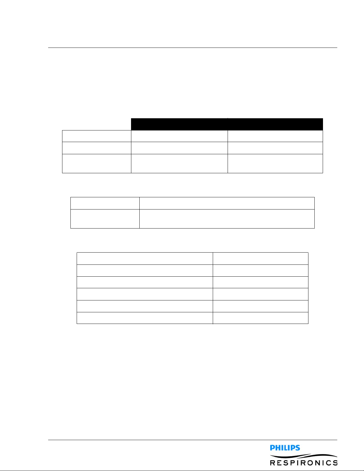
3.1 ENVIRONMENTAL
Operating Storage
Temperature 5 °C to 35° C (41° F to 95° F) -20° to 60° C (-4° F to 140° F)
Relative Humidity 15 to 95% (non-condensing) 15 to 95% (non-condensing)
Atmospheric Pressure 101 kPa to 77 kPa (approximately
0-7500 ft)
3.2 P
HYSICAL
Dimensions 29.2 cmW x 23.1 cm H x 19.0 cm D (11.5” W x 9.1” H x 7.5” D)
Weight 3.8 kg (8.4 lbs) (without detachable battery)
4.3 kg (9.4 lbs) (with detachable battery installed)
3.3 ELECTRICAL
AC Voltage Source 90 to 264 VAC, 50/60 Hz, 2A/1A
DC Power Source 12 VDC, 8.3A
Type of Protection Against Electric Shock Class II
Degree of Protection Against Electric Shock Type BF Applied Part
Degree of Protection Against Ingress of Water Exposure Protection, IP22
Mode of Operation Continuous
NA
3.4 SD CARD AND SD CARD READER
Use only SD Cards and SD Card readers available from Philips Respironics, including the following:
ScanDisk® Card Reader/Writer - SanDisk Image Mate - REF SDDR-99-A15
PAGE 3-2
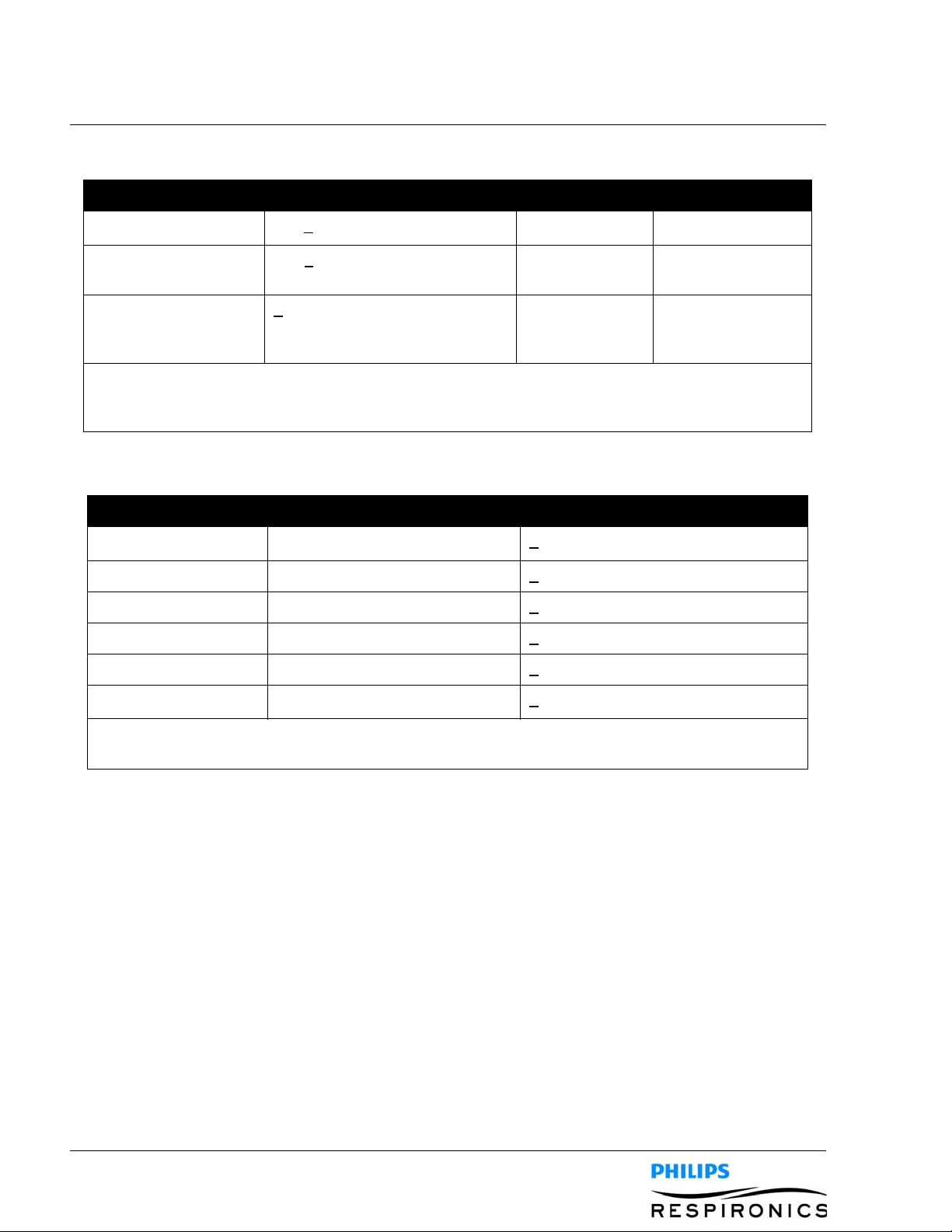
3.5 DISPLAYED PARAMETER ACCURACY
Parameter Accuracy Resolution Range
1099559, V
ER. 02
Pressure > of +
Peak Cough Flow
(PCF)
Inhale Tidal Volume
(vti)
Accuracies stated in this manual are based on specific environmental conditions. For stated accuracy,
the environmental conditions are: Temperature: 20-30 degrees C; Humidity: 50% relative; Altitude:
nominally 380 meters.
5 cmH2O or 10% of reading 1 cmH2O -70 to 70 cmH2O
5 lpm or 15% 1 lpm 0-500 lpm
> of +
(25 +0.15 of reading) for peak
+
flows greater than or equal to 20
lpm
1 ml 50-2000 ml
3.6 CONTROLLED ACCURACY
Parameter Range Accuracy
Pressure -70 to 70 cmH
Inhale Time 0-5 seconds +
Exhale Time 0-5 seconds +
Pause Time 0-5 seconds +
Frequency 1-20 Hz +
O+ 5 cmH2O
2
(10% of setting + 0.1 second)
(10% of setting + 0.1 second)
(10% of setting + 0.1 second)
(10% of setting)
Amplitude 1-10 cmH
Device performance and accuracy is specified at Temperature: 20-30 degrees C; Humidity: 50%
relative; Altitude: nominally 380 meters.
O+ 5 cmH2O
2
3.7 SOUND
The sound pressure of the device set at -40 cmH2O / +40 cmH2O in the Pause phase is less than 60 dBA at 1
meter.
3.8 DISPOSAL
Dispose of this device in accordance with local regulations.

3.9 STANDARDS COMPLIANCE
The device is designed to conform to the following standards
• IEC 60601-1: Medical Electrical Equipment, Part 1: General Requirement for Safety
• IEC 60601-1-2: Collateral Standard: Electromagnetic (EMC) Compatibility - Requirements and
tests.
• ISO 10993-1 Biological evaluation of medical devices - Part 1: Evaluation and testing (Biocompat-
ibility)
• RTCA/DO-160F section 21, category M; Emission of Radio Frequency Energy
PAGE 3-31099559, VER. 02
PAGE 3-4
1099559, V
ER. 02
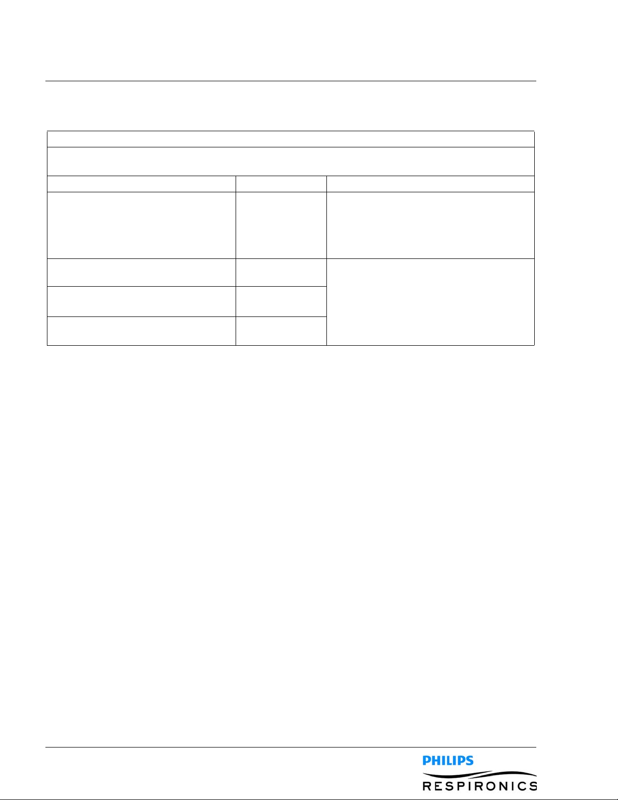
3.10 EMC INFORMATION
Guidance and Manufacturer’s Declaration - Electromagnetic Emissions
This device is intended for use in the electromagnetic environment specified below. The user of this device
should assure that it is used in such an environment.
Emissions Test Compliance Electromagnetic Environment - Guidance
RF Emissions
CISPR 11
Group 1 The Device uses RF energy only for its
internal function. Therefore, its RF emissions
are very low and are not likely to cause any
interference in nearby electronic equipment.
RF Emissions
CISPR 11
Harmonic Emissions
IEC 61000-3-2
Voltage Fluctuations/Flicker Emissions
IEC 61000-3-3
Class B The Device is suitable for use in all establish-
ments, including domestic establishments
Class A
Complies
and those directly connected to the public
low-voltage power supply network that supplies buildings used for domestic purposes.

PAGE 3-51099559, VER. 02
Guidance and Manufacturer’s Declaration - Electromagnetic Immunity
This device is intended for use in the electromagnetic environment specified below. The user of this device
should assure that it is used in such an environment.
Immunity Test IEC 60601 Test Level Compliance Level Electromagnetic Environment -
Guidance
Electrostatic
Discharge (ESD)
IEC 61000-4-2
+
6 kV Contact
8 kV Air
+
+
6 kV Contact
8 kV Air
+
Floors should be wood, concrete or
ceramic tile. If floors are covered with
synthetic material, the relative
humidity should be at least 30%.
Electrical Fast
Transient/Burst
IEC 61000-4-4
+
2 kV for Power
Supply Lines
1 kV for Input/Output
+
+
2 kV for Power
Supply Mains
NA
Mains power quality should be that of
a typical home or hospital
environment.
Lines
Surge
IEC 61000-4-5
1 kV Line to Line
+
2 kV Line to Ground
+
+
1 kV Line to Line
2 kV Line to Ground
+
Mains power quality should be that of
a typical home or hospital
environment.
Voltage Dips, Short
Interruptions and
Voltage Variations
on Power Supply
Input Lines
IEC 61000-4-11
<5% U
U
40% U
U
70% U
U
(>95% Dip in
T
) for 0.5 Cycle
T
(60% Dip in
T
for 5 Cycles
T)
(30% Dip in
T
) for 25 Cycles
T
< 5% U
U
40% U
U
70% U
U
(>95% Dip in
T
) for 0.5 Cycle
T
(60% Dip in
T
for 5 Cycles
T)
(30% Dip in
T
) for 25 Cycles
T
Mains power quality should be that of
a typical home or hospital
environment. If the user of the Device
required continued operation during
power mains interruptions, it is
recommended that the Device be
powered from an uninterruptible
power supply or battery.
Power Frequency
(50/60) Magnetic
Field
IEC61000-4-8
Note: U
is the A.C. mains voltage prior to application of the test level.
T
<5% U
U
(>95% Dip in
T
) for 5 Seconds
T
<5% U
U
(>95% Dip in
T
) for 5 Seconds
T
3 A/m 3 A/m Power frequency magnetic fields
should be at levels characteristic of a
typical location in a typical home or
hospital environment.
PAGE 3-6
1099559, V
Guidance and Manufacturer’s Declaration - Electromagnetic Immunity
This device is intended for use in the electromagnetic environment specified below. The user of this device
should assure that it is used in such an environment.
Immunity Test IEC 60601
Test Level
Compliance
Level
Electromagnetic Environment - Guidance
Portable and mobile RF communications equipm ent sh ould be
used no closer to any part of the Device, including cables, that
the recommended separation distance calculated from the
equation applicable to the frequency of the transmitter.
Recommended separation distance
Conducted RF
IEC 61000-4-6
Radiated RF
IEC 61000-4-3
3 Vrms
150 kHz to
80 MHz
a
3 V/m
80 MHz to
2.5 GHz
3Vrms d = 1.2
3 V/m
80 MHz to
d = 1.2
d = 2.3
2.5 GHz
√
P
√
P 80 MHz to 800 MHz
√
P 800 MHz to 2.5 GHz
where P is the maximum output power rating of the transmitter
in watts (W) according to the transmitter manufacturer and d is
the recommended separation distance in meters (m).
Field strengths from fixed RF transmitters, as determined by an
a
electromagnetic site survey,
compliance level in each frequency range.
should be less than the
b
Interference may occur in the vicinity of equipment marked with
the following symbol:
ER. 02
Note 1: At 80 MHz and 800 MHz, the higher frequency range applies.
Note 2: These guidelines may not apply in all situations. Electromagnetic propagation is affected by
absorption and reflection from structures, objects, and people.
a Field strength from fixed transmitters such as base st ations for radio (cellular/cordless) telephones and
land mobile radios, amateur radio, AM and FM radio broadcast and TV broadcast cannot be predicted
theoretically with accuracy. To assess the electromagnetic environment due to fixed RF transmitters, an
electromagnetic site survey should be considered. If the measured fiel d strength in the location in wh ich the
Device is used exceeds the applicable RF compliance level above, the Device should be observed to verify
normal operation. If abnormal performance is observed, additional measures may be necessary, such as
re-orienting or relocating the Device.
b Over the frequency range 150 kHz to 80 MHz, field strengths should be less than 3 V/m.
PAGE 3-71099559, VER. 02
Recommended Separation Distance Between Portable and Mobile RF Communication Equipment
and Device
This device is intended for use in the electromagnetic environment in which radiated RF disturbances are
controlled. The user of this device can help prevent electromagnetic interference by maintaining a minimum
distance between portable and mobile RF communica tion equipment (transmitters) and this device as
recommended below, according to the maximum output power of the communications equipment.
Rated
Maximum
Output Power
of Transmitter
150 kHz to 80 MHz
Separation Distance According to Frequency of Transmitter (meters)
d = 1.2
80 MHz to 800 MHz
√
P
d = 1.2
√
P
800 MHz to 2.5 GHz
d = 2.3
√
P
(Watts)
0.01 0.12 0.12 0.23
0.1 0.38 0.38 0.73
1 1.2 1.2 2.3
10 3.8 3.8 7.3
100 12 12 23
For transmitters rated at a maximum output power not listed abo ve, the recommended sep ar ation distan ce d
in meters (m) can be estimated using the equation applicable to the frequency of the transmitter, where P is
the maximum output power of the transmitter manufacturer.
Note 1: At 80 MHz and 800 MHz, the higher frequency range applies.
Note 2: These guidelines may not apply in all situations. Electromagnetic propagation is affected by
absorption and reflection from structures, objects, and people.

PAGE 3-8
1099559, V
ER. 02
This page intentionally left blank.
PAGE 4-11099559, VER. 02
CHAPTER 4: SYSTEM OVERVIEW & SETUP
4.0 CHAPTER OVERVIEW
This chapter details the specifics of the CoughAssist E70/CoughAssist T70 devices and how to change
settings.
4.1 DEVICE FEATURES
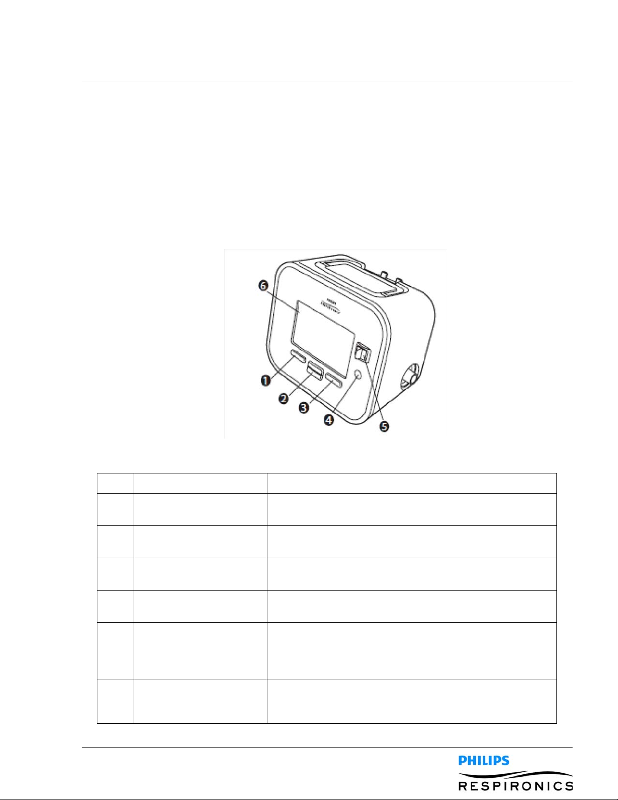
4.1.1 FRONT PANEL FEATURES
Item Description Function
1 Left Button This button allows you to select display options pr perform
certain actions specified on-screen.
2 Up/Down Button This button allows you to navigate the display menu and edit
device settings.
3 Right Button This button allows you to select display options or perform
certain actions specified on-screen.
4 Power On/Power Off
Button
5 Manual Switch The manual switch activates the exhale and inhale phases.
6 Display Screen The display screen allows you to view settings, system status
This button turns the device on or off.
Pressing the switch to the right (+) activates the inhale phase,
while pressing it to the left (-) activates the exhale phase.
Leaving the switch in the middle activates the pause phase.
information, real-time patient data, and logs. You can also
modify certain settings on the display screen.
PAGE 4-2
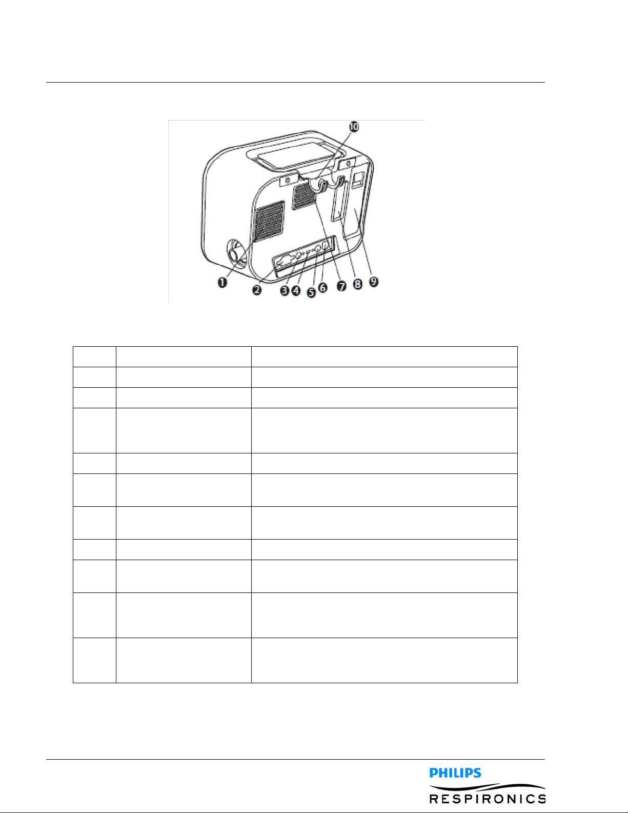
4.1.2 BACK PANEL FEATURES
Item Description Function
1099559, V
ER. 02
1 Fan Exhaust Location where air from inside the device is expelled.
2 AC Power Inlet Connect the AC Power cord here.
3 Remote Control Connector If you are using a remote control accessory (foot pedal)
to initiate manual therapy, connect the remote control
cable to this connector.
4 USB Connector Connect a USB cable to this connector for service only.
5SpO
Connector If you are using the optional Oximetry accessory,
2
connect the oximeter cable to this connector.
6 DC Power Inlet Connect an external battery here using the Philips
Respironics DC Power Cord.
7 Airpath Outlet Location where air exits the device.
8 Airpath Inlet (Filter Area) Location where the outside air enters the device. Insert
the filter supplied with device here.
9 Detachable Battery Slot If you are using the Philips Respironics Lithium-Ion
detachable battery to power the device , attach it here.
Remove the battery slot cap before use.
10 Tubing Retainer Route the tubing and mask through this bracket for
proper tubing management when the device is not in
use.
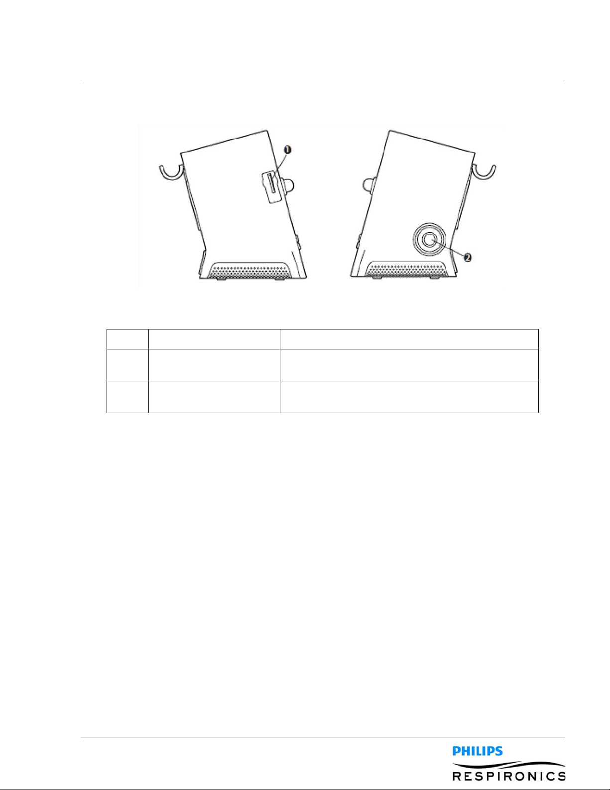
4.1.3 SIDE PANEL FEATURES
Item Description Function
PAGE 4-31099559, VER. 02
1 SD Card Slot You can insert the optional SD card into this slot if you
are recording patient data from the device.
2 Patient circuit connection You can connect your circuit tubing to this connector on
the device.
4.2 INHALATION/EXHALATION THERAPY MODES
4.2.1 MANUAL THERAPY MODE
Manual mode delivers therapy based on the Inhale Pressure and Exhale Pressure prescription settings. The
device delivers the set inhalation pressure for the amount of time that the Manual switch is held in the
inhalation position. The device delivers the set exhalation pressure for the amount of time that the Manual
switch is held in the exhalation position. Therapy starts in the pause phase when activated in Manual mode.
4.2.2 AUTO THERAPY MODE
Auto mode delivers therapy based on the following prescription settings: Inhale Pressure, Exhale Pressure,
Inhale Time, Exhale Time, and Pause Time.
Auto mode delivers pressure in the following sequence, repeating the sequence until the user exits the therapy
state:
1. Positive pressure at the Inhale Pressure setting for the duration of the Inhale Time setting.
2. Negative pressure at the Exhale Pressure setting for the duration of the Exhale Time setting.
3. Atmospheric pressure for the duration of the Pause Time setting.
When the Cough-Trak feature is enabled, Auto mode delivers pressure in the following sequence, repeating
the sequence until the user exits the therapy state:
1. Positive pressure at the Inhale Pressure setting when the device detects the patient’s effort to inhale for the duration of the Inhale Time setting.
2. Negative pressure at the Exhale Pressure setting for the duration of the Exhale Time setting.

PAGE 4-4
3. Atmospheric pressure until the device detects the next inspiratory effort.
1099559, V
ER. 02
4.3 THERAPY FEATURES
4.3.1 COUGH-TRAK
An important characteristic of the device is its ability to trigger on the patient’s inspiration to help synchronize
the therapy with the patient. This feature is known as Cough-Trak.
The Cough-Trak feature is available when the device is in Auto mode. The pressure delivery sequence is
synchronized with the patient’s effort to inhale.
When the Cough-Trak setting is activated in Auto mode, therapy starts in the Pause phase until patient effort is
detected.
When Cough-Trak is enabled, the Pause Time setting is disabled and the user cannot adjust the Pause Time
setting.
4.3.2 OSCILLATION (COUGHASSIST E70 ONLY)
The Oscillation therapy feature delivers an oscillatory therapy based on Frequency and Amplitude settings.
Use of the oscillation feature enhances mobilization and improves bronchial drainage. The oscillations will be
least apparent to the patient with lower amplitude and higher frequency settings.
If the Oscillation setting is enabled, the user can choose to apply the oscillation to the Inhale, Exhale, or Both
(inhale and exhale) phases. The Frequency and Amplitude settings can be changed as needed. See Chapter 4
for more details on the Oscillation, Frequency, and Amplitude settings.
4.4 OPERATING THE COUGHTASSIST E70/COUGHASSIST T70
To navigate through all of the menu Screens and settings:
• Use the up/down button to scroll through the menu.
• Use the left/right buttons to perform the actions specified on the on-screen buttons.
4.4.1 SCREEN TIMEOUT PERIODS
The following timeout periods occur due to device inactivity:
• Monitor Screen - Has a timeout period of ten minutes when therapy is not being delivered. The
timer restarts when a key is touched, the manual switch is toggled in manual mode, or a patient
effort is detected in auto mode when CoughTrak is enabled. When time expires, the device
returns to the standby screen.
• Standby Screen - Has a timeout period of ten minutes. The timer restarts when a key is touched or
the Manual switch is toggled. When time expires, the screen turns off.
• Menu/Settings Screens - Any screen displaying a menu or log has a timeout period of five min-
utes. The timer restarts when a key is touched. When the timer expires, the action of the Left soft
key is taken.
• Menu Items - Individual menu items on the Settings or Options screens have a timeout period of
30 seconds. The timer restarts when a key is touched. When the timer expires, the action of the
Left soft key is taken.
• Confirmation Messages - Confirmation messages have a timeout period of 30 seconds. When
time expires, the message is removed from the screen and the previous screen is displayed.

PAGE 4-51099559, VER. 02
4.4.2 ACCESSING THE STANDBY SCREEN
1. Press the button, and the Startup screen appears momentarily, indicating the software ver-
sion.
2. The Standby screen then appears. It displays the date and time, therapy mode, a patient accessory panel (if a patient accessory is attached), a status panel, and the soft key panel.
3. You can perform the following actions from the Standby screen:
a. If an accessory module is attached, you can monitor the connection to any attached patient
accessory.
b. Modify patient settings by selecting the Left (Settings) key.
c. Access the menu by selecting the Up (Menu) key.
d. Initiate therapy by selecting the Right (Therapy) key. Selecting this key starts the airflow and
displays the Monitoring screen.
4.4.3 ACCESSING THE MONITOR SCREEN
The Monitor screen appears after you press the Therapy key on the Standby screen. There are two versions of
this screen: Detailed View Off and Detailed View On. Samples of both screens are shown below.
PAGE 4-6
1099559, V
ER. 02
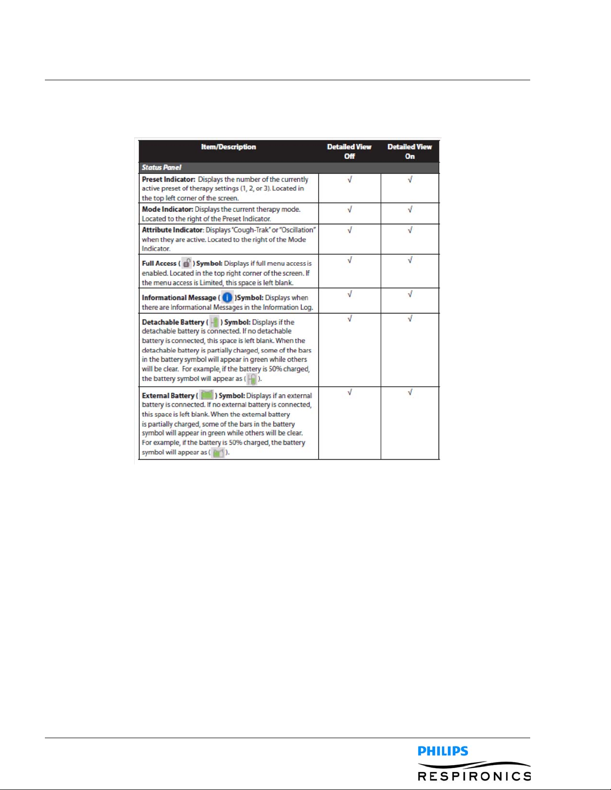
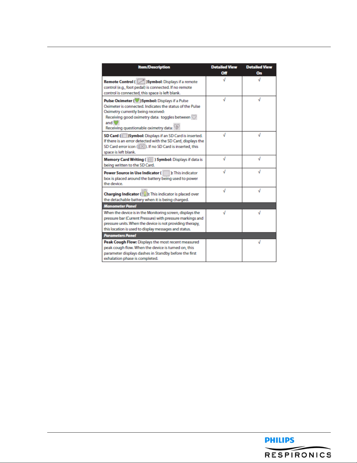
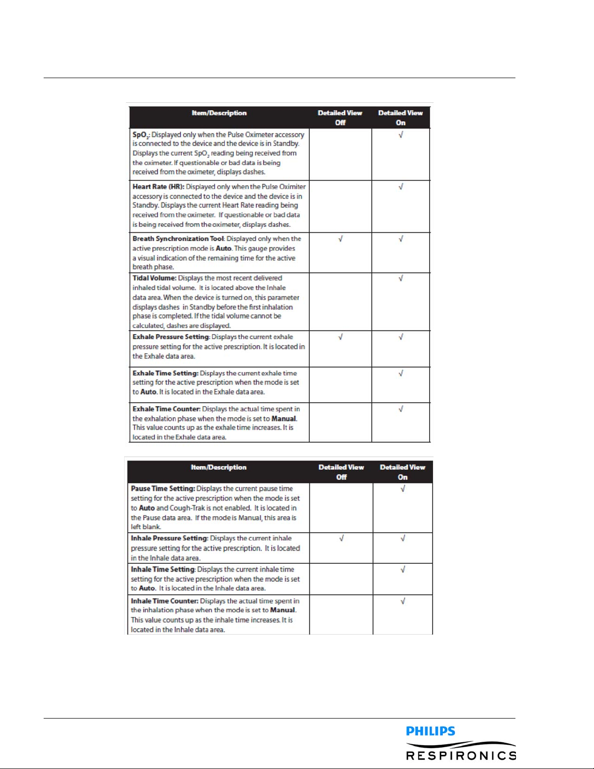
4.4.4 MONITOR SCREEN CONTENT
The Monitor screen is divided into several sections, the Status panel, Manometer panel, Parameters panel,
and the Soft buttons panel. The following information is shown on the Monitor screen:
PAGE 4-71099559, VER. 02
PAGE 4-8
1099559, V
ER. 02
The Soft buttons panel appears at the bottom of the screen. The button selection varies depending on what
screen is displayed.
4.4.5 CHANGING DEVICE SETTINGS
1. Press the Up key to enter the Main Menu screen from the Standby or Monitor screens.
2. Choose from the following selections on the Main Menu screen:
• Options: View and change device settings, such as Full or Limited Access mode, Detailed View,
Language, etc.
• Data: View patient and device data such as SpO2, Heart Rate, SD Card capacity, Therapy Hours,
etc.
• Information Log: View informational messages generated by the device.
• Clear Patient Data: This option allows you to clear patient data from the device’s internal memory.
If an SD Card is inserted, all patient data stored on the SD Card is also cleared.
• Safely Remove SD Card: This option will appear if an SD Card is inserted in the device. Select this
option when you want to remove the SD Card. When the “Remove SD Card” confirmation message appears, remove the card. If you press the left (cancel) button or don’t remove the card within
30 seconds, the confirmation message will close and the device will continue writing to the card.
• Write Event Log to SD Card: This option allows you to copy event log data from the device to the
SD Card.
4.4.6 CHANGING OPTIONS MENU SETTINGS
1. From the Standby or Therapy screen, press the Menu key to enter the Main Menu.
2. Highlight Options on the Main Menu screen and press the Right soft key (Select).
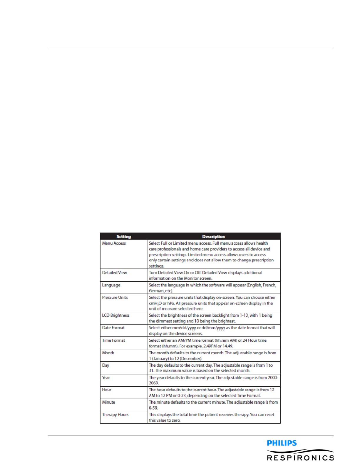
3. The following settings appear on the Options screen when the device is in Full Access mode:
PAGE 4-91099559, VER. 02
 Loading...