

Philips BiPAP A30, Respironics BiPAP A30 Setup Manual
Set-up guide
1
2
3
4
6
5
Getting started
Main screen
Menus
Humidification
Guidelines for ventilation set-up
Connection to oximetry
Philips Healthcare is part of
Royal Philips Electronics
How to reach us
www.philips.com/healthcare
healthcare@philips.com
Asia
+49 7031 463 2254
Europe, Middle East, Africa
+49 7031 463 2254
Latin America
+55 11 2125 0744
North America
+1 425 487 7000
800 285 5585 (toll free, US only)
Philips Respironics
1010 Murry Ridge Lane
Murrysville, PA 15668
Customer Service
+1 724 387 4000
+1 800 345 6443 (toll free)
Philips Respironics International
Headquarters
+33 1 47 28 30 82
Philips Respironics Asia Pacific
+65 6882 5282
Philips Respironics Australia
+61 2 9666 4444
Philips Respironics China
+86 400 828 6665
+86 800 828 6665
Philips Respironics Deutschland
+49 8152 93 06 0
Philips Respironics France
+33 2 51 89 36 00
Philips Respironics Italy
+39 039 203 1
Philips Respironics Switzerland
+41 6 27 45 17 50
Philps Respironics United Kingdom
+44 800 1300 845
www.philips.com/respironics
BiPAP A30
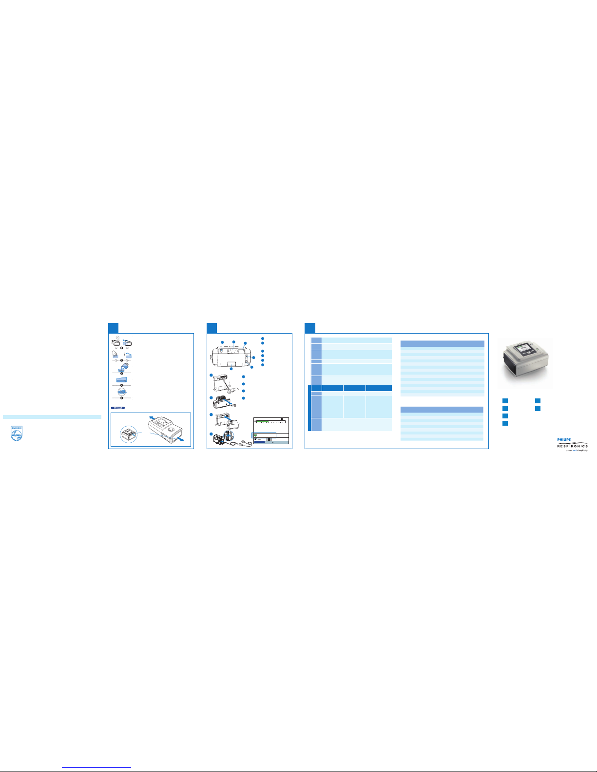
Humidification
4
On the Standby scree n, if a humidifier is con nected, you can selec t
so humidifier prehe ats before therapy is d elivered.
With device turned of f, remove and fill chamb er
with water.
1. (a) Lift humidif ier door until it lock s in place. Do
not force door higher tha n the locked position.
(b) Grasp front of chamb er and slide toward you.
2. (a) Gently push tab locat ed inside round opening
on top of chamber. (b) Separ ate top and bottom
of chamber.
3. Fill bottom chamber with distilled water.
4. Observe maxi mum fill lines locate d on sides
of chamber.
5. Do not overfill.
Reassemble the cha mber by placing the hinge s
on lid over the two tabs on b ack of chamber.
Close lid until it lock s in place with an audible
click. Insert f illed chamber into hu midifier.
Release
latch
Humidication
Withdevice turnedo, removeand fill chamberwith water.
1.(a) Lifthumidifier door untilit locksin place. Donot force
doorhigher thanthe locked position.(b) Graspfront of
chamberand slidetoward you.
2.(a) Gentlypush tab locatedinside roundopening on top
ofchamber.(b) Separate topand bottom ofchamber.
3.Fill bottomchamber with distilledwater.
4.Observe maximumfill lines locatedon sidesof chamber.
5.Do notoverfill.
Reassemblethe chamberby placingthe hingeson lid overthe
twotabs onback of chamber.Close liduntil itlocks in place
withan audibleclick. Insert filledchamber into humidifier.
(bottom
view)
Undocking the
humidifier
Connection to oximetry
5
Nurse call connect or
Accessory slot
(cover shown)
SD card slot
DC power inlet
AC power inlet
Filter area
6
5
4
3
2
1
5
6
4
3
2
1
To plug the oximetry modul e:
A
Remove the cover from the acces sory
slot at the back of the Bi PAP A30.
B
Remove the cover from the oximetry
accessory.
C
Plug the oximetry a ccessory into the
accessory slot.
D
Plug the oximetry s ensor of your choice
to the oximetry module.
When the oximetr y module is connected ,
the SpO2 and heart rate val ues are
monitored on the mai n screen (see below).
Back of device
A
B
C
D
Humidifier
cm
H
2
O
cm
H2O
ml l/min
l/min
BPM
S/T AVAPS: 0.5
0 5 10 15 20 25 30
Menu
Pressure
12.1
Vte
0
Leak
0.0
MinVent
0.0
Heart Rate
79
SpO
2
85
RR
12
I:E Ratio
1:1.0
A
2
Guidelines for ventilation set-up
6
Conversion table to set the inspiratory time for controlled breaths
Set back up breath r ate
(BPM)
I/E 1/3,
Ti/Ttot 25%
I/E 1/2,
Ti/Ttot 33%
I/E 1/1,
Ti/Ttot 50%
10 1.5 s 2.0 s 3.0 s
11 1.4 s 1.8 s 2.7 s
12 1.3 s 1.7 s 2.5 s
13 1.2 s 1.5 s 2.3 s
14 1.1 s 1.4 s 2.1 s
15 1.0 s 1.3 s 2.0 s
16 0.9 s 1.3 s 1.8 s
17 0.9 s 1.2 s 1.7 s
18 0.8 s 1.1 s 1.6 s
19 0.8 s 1.1 s 1.5 s
20 0.8 s 1.0 s 1.5 s
21 0.7 s 1.0 s 1.4 s
22 0.7 s 0.9 s 1.3 s
23 0.7 s 0.9 s 1.3 s
24 0.6 s 0.8 s 1.2 s
25 0.6 s 0.8 s 1.2 s
Set the inspirat ory time in seconds : Ti (Second) = 60/Re spiratory rat e x % Ti
Conversion tabl e to set the target t idal volume in rela tion to the ideal we ight
Height Calculated ideal
weight (if BMI = 23)
Target Vte
if 8 ml/kg
Target Vte
if 10 ml/kg
1.50 m 52.0 kg 410 ml 520 ml
1.55 m 55.0 kg 440 ml 550 ml
1.60 m 59.0 kg 470 ml 590 ml
1.65 m 62.5 kg 500 ml 620 ml
1.70 m 66.5 kg 530 ml 660 ml
1.75 m 70.5 kg 560 ml 700 ml
1.80 m 74.5 kg 600 ml 740 ml
1.85 m 78.5 kg 630 ml 780 ml
1.90 m 83.0 kg 660 ml 830 ml
Calculated with a n ideal Body Mass I ndex of 23 kg/m
2
(BMI = weight/height2)
Important: Guidelines are int ended to serve onl y as a reference. They s hall be
used only in conjunc tion with the inst ructions and/or pr otocol set forth by t he
physician and inst itution in which th e assist device is be ing used. The guide lines are
not intended to supe rsede establi shed medical prot ocols.
Initial
settings
IPAP = 8 to 10 cmH2O, EPAP = 4 cmH2O and RR = 10 to 12 BPM
IPAP Increase IPAP if the p atient wants more a ir, targeting patien t tidal
volume at 8 ml/Kg of ide al weight
EPAP •without SAS: 4 – 5 cmH
2
O
•with S AS: increase EPAP to r emove obstructi ve apnea events
•with in trinsic PEP (stab le chronic COPD): 5 – 6 cmH
2
O
BPM Set to 2 – 3 BPM under patient ’s spontaneous fre quency
Rise
time
Obstructive pat ients prefer shor t rise time:
from 1 to 4 (100 ms to 400 ms)
Restrictive pati ents prefer long ri se time: from 3 to 6
(300 ms to 600 ms)
Ti Set Ti between 25% an d 33% for obstructive p atients
Set Ti between 33% and 5 0% for restricti ve patients
(refer to table oppos ite)
AVAPS
OHS COPD Other restrictive
diseases (NMD, etc.)
Vt target 8 to 10 ml/kg of ideal bo dy weight (refer to ta ble opposite)
IPAP
window
(IPAPmin
and
IPAPmax )
Allow a wide range
of pressure variati on
to ensure the right
pressure at the right
time.
•IPA Pmin = E PAP
•IPA Pmax =
25 – 30 cmH
2
O
Allow a more
restrictive pressure
window to combine
comfort and eff icacy.
•IPAPmi n =
comfortable IPAP
•IPA Pmax =
IPAPmin + 5
Allow a more restric tive
pressure window to
combine comfort an d
safety.
•IPAPmin =
efficient IPAP
•IPA Pmax =
IPAPmin + 5
AVAPS
rate
AVAPS rate setting dep ends on patient ne eds and clinical c ondition:
0.5 cmH
2
O/min to 3 cmH2O/min so target tidal vo lume is reached sm oothly
3 cmH
2
O/min to 5 cmH2O/min so target tidal vo lume is reached
more rapidly
Check patient ar terial blood gas es (PaCO2 and PaO2) and oxygen satura tion (SpO2)
© 2011 Koninklijke Philips E lectronics N .V. All rights are reser ved.
Philips Healthcar e reserves the r ight to make chan ges in specifi cations and/or t o
discontinue any produ ct at any time with out notice or obli gation and will n ot be
liable for any conseque nces resultin g from the use of thi s publication .
Broudy NA 9/26/11 12NC 4522962765 61 MCI 4104424 PN 1093370
Please visit w ww.philips.co m/respironic s to find out mor e
BiPAP A30 is registere d trademark of P hilips.
Main screen Menus
2 3
Menu: Settings and alar ms
Mode CPAP, S, S/T, PC, T
Flex Lock (only in S mode) On (patient cannot adju st Flex level)
Off (patient can a djust Flex level)
Flex (only in S mode) Off/1/2/3
AVAPS On/off
AVAPS rate From 0.5 cmH
2
O/min up to
5 cmH2O/min per 0.5 cmH2O/min step
Tidal volume
(only when AVAPS is enabled)
200 - 1500 ml
per 10 ml step
IPAP max
(only when AVAPS is enabled)
IPAPmin - 30 cmH
2
O
per 0.5 cmH2O step
IPAP min
(only when AVAPS is enabled)
4 - IPAPmax
per 0.5 cmH
2
O step
EPAP 4 - 25 cmH
2
O per 0.5 cmH2O step
Breath rate 0 to 40 bpm (4-40 bp m for T mode)
Inspiratory time 0.5 to 3 sec. per 0.1 sec. s tep
Rise time lock On (patient cannot a djust rise time)
/Off (patient can a djust rise time)
Rise time 1 (fastest) to 6 (slowest)
Ramp length 0 to 45 minutes per 5 minutes s tep
Ramp start pres sure From 4 cmH
2
O to prescribed EPAP per
1 cmH2O step
System One humidification On (System One humidi ty control)/
Off (classic mode)
Humidifier 1 (coo lest) to 5 (hottest)
Humidifier Ramp
cm
H
2
O
cm
H2O
ml l/min
l/min
BPM
S/T AVAPS: 0.5
0 5 10 15 20 25 30
Menu
Pressure
12.1
Vte
325
Leak
30.0
MinVent
3.9RR 12
I:E Ratio
1:3.0
A
1
AVAPS activated
with a speed rate
of 0.5 cmH
2
O/min.
Breath
indicator
(patient or
machine settable
in Option s)
Device
unlocked
Humidifier
connected,
setting 1
Pressure bar graph
Real-time
monitored values
when detailed
view ON (Options
setting s)
Mode of ventilation
External batt ery
connected and
in use
SD Card
inserted
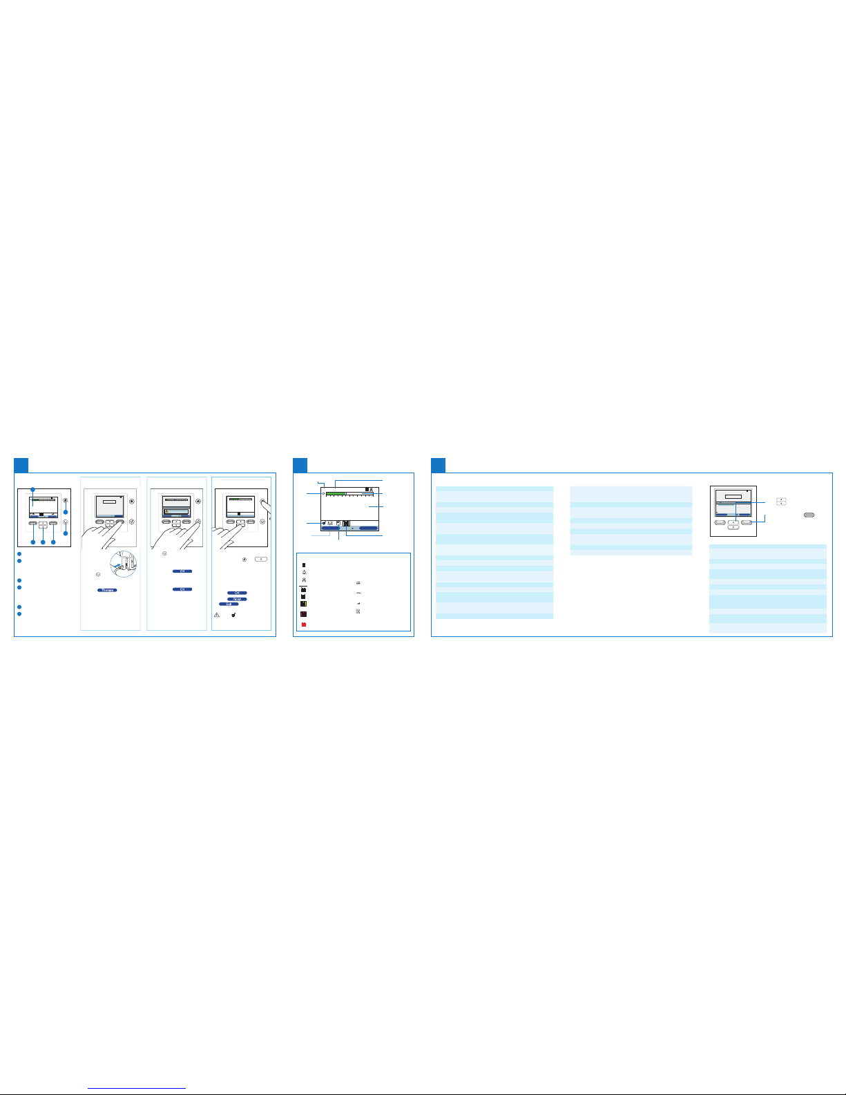
Symbols and icons
FLEX enabled
FLEX enabled and FLEX setting
(eg. 1)
Humidifier connected and
Humidifier setting (eg. 1)
Bad humidifier state
(flashing symbol displays)
Ramp activated
SD Card error
(bad memory card inserted)
AVAPS
A
AVAPS
AVAPS: 1
AVAPS
AVAPS: 1
FLEX
FLEX: 1
1
AVAPS
AVAPS: 1
FLEX
A
AVAPS
AVAPS: 1
FLEX
FLEX: 1
A
1
AVAPS
AVAPS: 1
A
AVAPS
AVAPS: 1
FLEX
FLEX: 1
A
AVAPS
AVAPS: 1
FLEX
FLEX: 1
1
AVAPS
AVAPS: 1
FLEX
FLEX: 1
1
AVAPS
AVAPS: 1
FLEX
FLEX: 1
AVAPS
AVAPS: 1
FLEX
FLEX: 1
A
1
AVAPS
AVAPS: 1
FLEX
A
AVAPS
AVAPS: 1
FLEX
AVAPS
AVAPS: 1
FLEX
FLEX: 1
Apnea alarm enabled
Audio pause is active
Circuit disconnect
alarm enabled
External battery is 80% capacity
External battery is 20% capacity
External battery has less than
20 minutes left
External battery has less than
10 minutes left
External battery is empty
Getting started
1
Display screen
Perform action spe cified on screen
(humidifier setting, cancel action
or exit menu)
Navigate menus or ch ange settings
Perform action spe cified on screen
(activate ramp, sel ect/modify/
confirm parameters)
Audio pause button
Start/stop button
6
5
4
3
2
1
Humidifier Ramp
cm
H
2
O
S/T AVAPS: 0.5
0 5 10 15 20 25 30
Menu
12/30/2010
06:12 PM
A
1
1
2 3
4
5
6
How to stopHow to start therapyDevice navigation
•Connect the
device to AC
or DC power
source
•Press
to
switch on the
device
•Select
to start
the treatment
Navigate
OK
Cancel
cm
H
2
O
cm
H
2
O
ml l/min
S/T
0 5 10 15 20 25 30
Pressure
3.5
Vte
0
ml
RR
20
Leak
0.0
Standby
Power Off
S/T AVAPS: 0.5
Menu
Setup
Therapy
A
12/30/2010
06:12 PM
•Press
•To keep power on but stop
the blower, select ‘Sta ndby’
•Then select
•To turn power off, sele ct
‘Power Off’
•Then select
How to unlock
To unlock the device
•Press and hold
and
for a few seconds to access
Setup page
•Scroll down and se lect ‘Options’
•Modify ‘M enu access’ from
‘Limited’ to ‘Full’
•Press
to validate
•Press
and
to come back to
the main screen
When
appears on the main
screen, the device is u nlocked.
cm
H
2
O
cm
H
2
O
ml l/min
l/min
BPM
S/T AVAPS: 5.0
0 5 10 15 20 25 30
Menu
Pressure
12.6
Vte
0
Leak
0.0
MinVent
0.0RR 11
I:E Ratio
1:1.0
To navigate through the Opti ons
menu:
•Use
to scroll
through the menu.
•Usetheleftandright
buttons to perf orm the actions
specified on the o n-screen buttons
and set according to your pre ference.
Menu: Options
Menu: Alarm and Event Logs
Menu: Settings and alar ms (cont.)
Tubing type lock On (patient cannot ad just tubing size
diameter)/Off (patient can adjust
tubing size diamete r)
Tubing type 15 mm/22 mm
System One resistance lock On (patient cannot s et mask type)/
Off (patient can s et mask type)
System One resista nce (mask type) 0, X1, X2, X3, X4 or X5
Circuit disconnect alarm Off ; 15 or 60 sec.
Apnea alarm Off; 10, 20 or 30 sec .
Low tidal volume alarm
(only when AVAPS is enabled)
On/off
Low minute ventilation alarm Off; 1 to 9 9 lpm
High respirator y rate alarm Off; 4 to 60 BPM
Menu access Full (device unlocked)/Limited (device locked)
Detailed view O n (monitored data appea r on the main screen)/Off
(no monitored data on sc reen, but time and date)
Language You have the choice between 22 diffe rent languages
Pressure units cmH
2
O/hPa
Breath indicator Patient (spontaneous breath)
/machine (controlled breath)
Keypad lock On (buttons a re inactive)/off (butto ns are active)
Keypad backlight On/off
LCD brightness 1 (darkest) to 10 (lighte st)
Screen saver Dim (backlight is decreased)/Breath (black screen,
but manometer and breath indicator are visible)/
Off (no screen saver)
Date & time format Da te and time settings
Blower hours Number of hours the blowe r has been active
(resett able)
Therapy hours Nu mber of hours the patie nt receives therapy
(resett able)
Menu access Full
Detailed view ON
Language English
Pressure units cmH20
Breath Indicator Patient
Menu
Options
S/T AVAPS: 0.6
1/18
Navigate
Setup
Modify
Finish
A
Under ‘Options’, you have acce ss to the following para meters:
Alarm Log
The alarm log lists the 20 most recent al arms or messages that
appeared on the device display.
Event Log
The event log displays a lis t of all events that have occur red,
in chronological order.
 Loading...