

Philips QTLP670C installation Guide
)
)
)
)
)
)
)
0
)
0
)
)
)
K
)
)
Ø
[
Ø
]
)
OM
SIDE
OP
W
_
_
7
Y
查询QTLP670C-2供应商
SURFACE MOUNT LED LAMP
STANDARD BRIGHT PLCC-2
QTLP670C
QTLP670C-2 HER
QTLP670C-7 AlGaAs Red
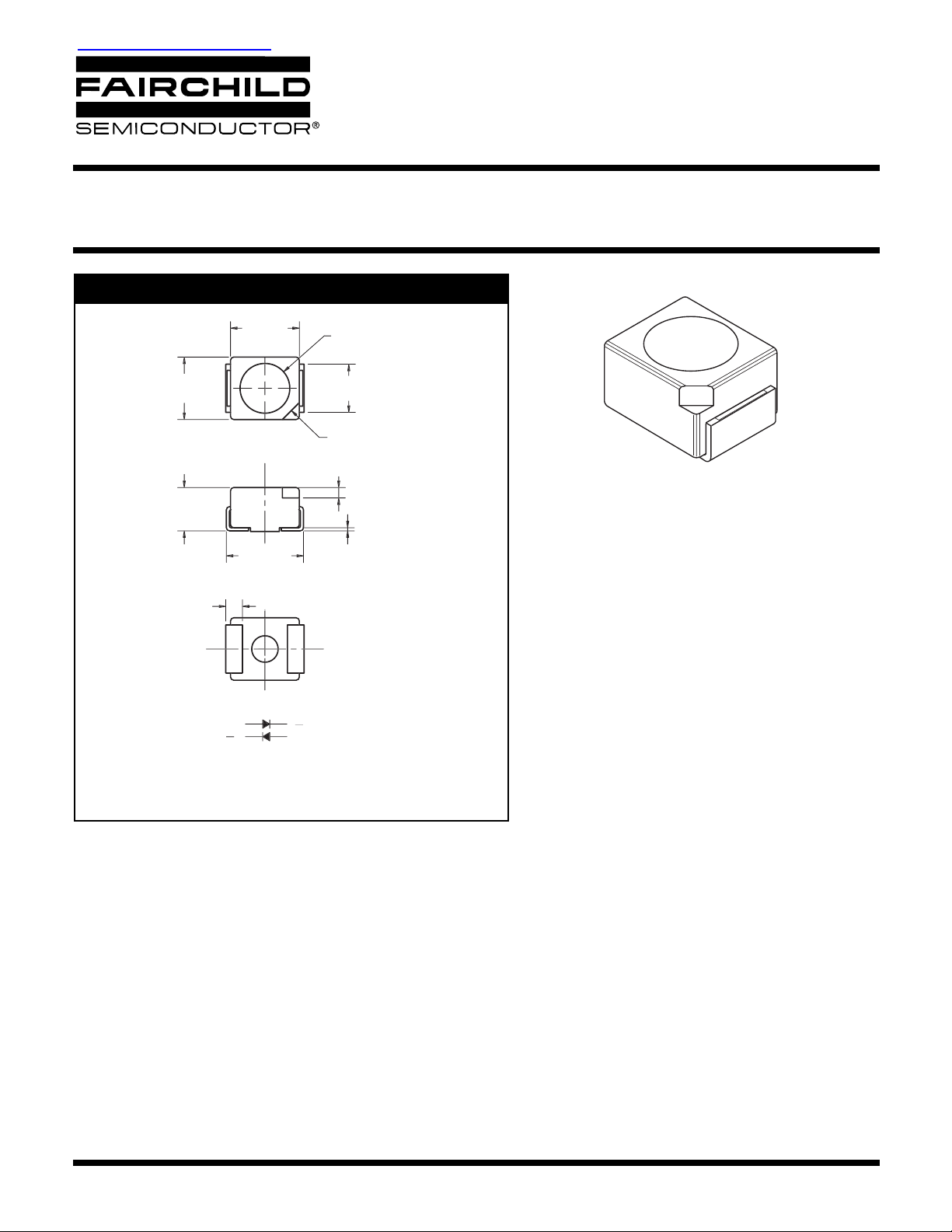
PACKAGE DIMENSIONS
0.130 (3.3
0.114 (2.9
0.118 (3.0
0.102 (2.6
T
0.083 (2.1
0.067 (1.7
0.146 (3.7
0.130 (3.3
0.032 (0.8
0.094
2.4
0.091 (2.3
0.083 (2.1
POLARITY MAR
.024 (0.6
.016 (0.4
0.006 (0.15
QTLP670C-3 Yellow
QTLP670C-B Blue
QTLP670C-4 Green
QTLP670C-W White
BOTT
for -2, -3, -4, -9, -B and
for -
POLARIT
NOTE:
Dimensions for all drawings are in inches (mm).
APPLICATIONS
• Automotive interior lighting
• Status indication for consumer electronics and office
equipment
DESCRIPTION
These surface mount LEDs are designed with flat top and sides for the ease of pick-and-place by automatic placement equipment.
They are compatible with convective IR and vapor phase reflow soldering. The package size and configuration conform to EIA-535
BAAC standard specification for case size 3528 tantalum capacitor. These LEDs are ideal for backlighting and optical coupling into
light pipes.
FEATURES
• GaN/SIC technology for -B and -W
• Wide viewing angle of 120°
• Water clear optics
• Moisture-proof packaging
• Available in 0.315" (8mm) width tape on 7" (178mm) diameter reel; 2,000 units per reel
© 2003 Fairchild Semiconductor Corporation
Page 1 of 7
9/3/03
∆λ
SURFACE MOUNT LED LAMP
STANDARD BRIGHT PLCC-2
QTLP670C
QTLP670C-2 HER
QTLP670C-7 AlGaAs Red
ABSOLUTE MAXIMUM RATINGS
Parameter Symbol
Continuous Forward Current I
Peak Forward Current
(f = 1.0 KHz, Duty Factor = 1/10)
Reverse Voltage (I
Power Dissipation P
Operating Temperature T
Storage Temperature T
Lead Soldering Time T
= 10 µA) V
R
QTLP670C-3 Yellow
QTLP670C-B Blue
(T
=25°C Unless otherwise specified)
A
-2 -3 -4 -7 -B -W
F
I
FM
555555V
R
D
OPR
STG
SOL
30 30 30 30 30 30 mA
160 160 160 180 100 100 mA
84 84 84 72 135 135 mW
ELECTRICAL / OPTICAL CHARACTERISTICS
(T
A
QTLP670C-4 Green
QTLP670C-W White
QTLP670C
Units
-40 to +85 °C
-40 to +90 °C
260 for 5 sec °C
=25°C)
Part Number Symbol
Luminous Intensity (mcd)
Minimum
Typical 10 10 25 40 30 30
Forward Voltage (V)
Maximum
Typical 2.0 2.0 2.1 1.9 3.8 3.8
Wavelength (nm)
Peak
Dominant
Chromatic Coordinate x,y —————
Spectral Line Half Width (nm)
Viewing Angle (°)2
I
V
V
F
λ
P
λ
D
Θ
1/2
-2 -3 -4 -7 -B -W
5 5 15 25 20 20
2.8 2.8 2.8 2.4 4.5 4.5
635 585 565 660 430 —
630 590 570 645 465 —
45 35 30 20 65 — I
120 120 120 120 120 120 I
QTLP670C
x = 0.26
y = 0.28
Condition
I
= 20mA
F
I
= 20mA
F
I
= 20mA
F
I
= 20mA
F
= 20mA
F
= 20mA
F
© 2003 Fairchild Semiconductor Corporation
Page 2 of 7
9/3/03
SURFACE MOUNT LED LAMP
STANDARD BRIGHT PLCC-2
QTLP670C
QTLP670C-2 HER
QTLP670C-7 AlGaAs Red
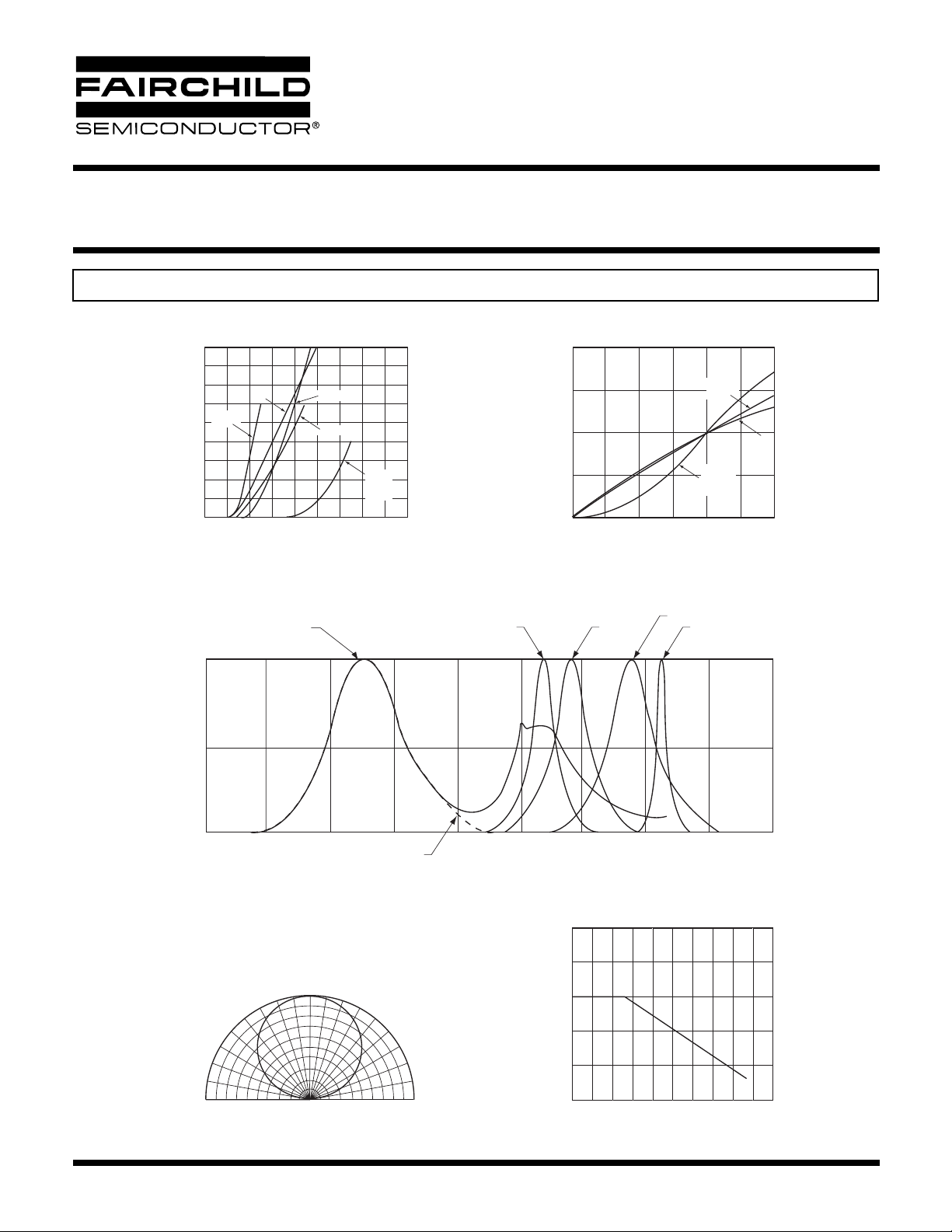
TYPICAL PERFORMANCE CURVES
Fig. 1 Forward Current vs. Forward Voltage
90
80
70
60
50
40
30
20
- FORWARD CURRENT (mA)
10
F
I
0
1.0 2.0 3.0 4.0
HER
AlGaAs
RED
VF - FORWARD VOLTAGE (V)
WHITE
GREEN
YELLOW
BLUE
&
WHITE
QTLP670C-3 Yellow
QTLP670C-B Blue
Fig. 2 Relative Luminous Intensity vs.
2.0
1.5
1.0
0.5
(NORMALIZED AT 20 mA)
RELATIVE LUMINOUS INTENSITY
0.0
5.0
Fig. 3 Relative Intensity vs. Peak Wavelength
GREEN
0 5 10 15 20 25 30
QTLP670C-4 Green
QTLP670C-W White
DC Forward Current
AlGaAs
RED
HER
YELLOW
GREEN
I
- DC FORWARD CURRENT (mA)
F
HER
AlGaAs REDYELLOW
BLUE
&
WHITE
1.0
0.5
RELATIVE INTENSITY
0
300 350 400 450 500 550 600 650 700 750
Fig.4 Radiation Diagram
0˚
-10˚ 10˚
-20˚ 20˚
-30˚ 30˚
-40˚ 40˚
-50˚ 50˚
-60˚ 60˚
-70˚ 70˚
-80˚ 80˚
-90˚
1.0 0.8 0.6 0.4 0.2 0 0.2 0.4 0.6 0.8 1.0
REL. LUMINOUS INTENSITY (%)
BLUE
WAVELENGTH (nm)
90˚
Fig.5 Maximum Forward Current
50
40
30
20
10
- FORWARD CURRENT (mA)
F
I
0
vs. Ambient Temperature
020406080
TA - AMBIENT TEMPERATURE (˚C)
100
© 2003 Fairchild Semiconductor Corporation
Page 3 of 7
9/3/03
 Loading...