

PHILIPS PTV910, PTV914 Service Manual

Philips Consumer Electronics
Technical Service Data
Service and Quality
Service Publications Dept.
One Philips Drive
P.O. Box 14810
Knoxville, TN 37914
IMPORTANT SAFETY NOTICE
First Published: 05-17-2001
Rev. Date: 09-30-2004
Print Date: 09-30-2004
Safety Notes
WARNING
SAFETY CHECKS
- FIRE AND SHOCK HAZARD
- IMPLOSION
- X-RADIATION
- LEAKAGE CURRENT COLD CHECK
- LEAKAGE CURRENT HOT CHECK
- PICTURE TUBE REPLACEMENT
- PARTS REPLACEMENT
TV SAFETY NOTES
SAFETY PRECAUTIONS FOR TV CIRCUITS
PRECAUTIONS DURING SERVICE
SAFETY CHECK AFTER SERVICING
PRODUCT SAFETY GUIDELINES FOR ALL PRODUCTS
PREVENTION OF ELECTROSTATIC DISCHARGE (ESD)
REFER TO SAFETY GUIDELINES
SAFETY NOTICE: ANY PERSON ATTEMPTING TO SERVICE THIS CHASSIS MUST FAMILIARIZE
HIMSELF WITH THE CHASSIS AND BE AWARE OF THE NECESSARY SAFETY PRECAUTIONS
TO BE USED WHEN SERVICING ELECTRONIC EQUIPMENT CONTAINING HIGH VOLTAGES.
CAUTION: USE A SEPARATE ISOLATION TRANSFORMER FOR THIS UNIT WHEN SERVICING
© Philips Electronics North America Corporation Visit our World Wide Web Site at http://www.forceonline.com
GENERAL SAFETY NOTES
A
IMPORTANT SAFETY NOTICE
Proper service and repair is important to the safe, reliable operation of all Philips Consumer Electronics
Company** equipment. The service procedures recommended by Philips and described in this service
manual are effective methods of performing service operations. Some of these service operations require
the use of tools specially designed for the purpose. The special tools should be used when and as
recommended.
It is important to note that this manual contains various CAUTIONS and NOTICES which should be
carefully read in order to minimize the risk of personal injury to service personnel. The possibility exists
that improper service methods may damage the equipment. It also is important to understand that
these CAUTIONS and NOTICES ARE NOT EXHAUSTIVE. Philips could not possibly know, evaluate
and advise the service trade of all conceivable ways in which service might be done or of the possible
hazardous consequences of each way. Consequently, Philips has not undertaken any such broad
evaluation. Accordingly, a servicer who uses a service procedure or tool which is not recommended by
Philips must first satisfy himself thoroughly that neither his safety nor the safe operation of the
equipment will be jeopardized by the service method selected.
** Hereafter throughout this manual, Philips Consumer Electronics Company will be referred to as
Philips.
WARNING
Critical components having special safety characteristics are identified with a or "S" by the Ref. No.
in the parts list and enclosed within a broken line* (where several critical components are grouped in one
area) along with the safety symbol on the schematics or exploded views. Use of substitute
replacement parts which do not have the same specified safety characteristics may create shock, fire, or
other hazards. Under no circumstances should the original design be modified or altered without written
permission from Philips. Philips assumes no liability, express or implied, arising out of any unauthorized
modification of design. Servicer assumes all liability.
• Broken Line ____ _ ____ _ ____ _ ____
SAFETY CHECKS
fter the original service problem has been corrected, a complete safety check should be made. Be sure
to check over the entire set, not just the areas where you have worked. Some previous servicer may
have left an unsafe condition, which could be unknowingly passed on to Your customer. Be sure to
check all of the following:
FIRE AND SHOCK HAZARD
IMPLOSION
X-RADIATION
LEAKAGE CURRENT COLD CHECK
LEAKAGE CURRENT HOT CHECK
PICTURE TUBE REPLACEMENT

PARTS REPLACEMENT
FIRE AND SHOCK HAZARD
1. Be sure all components are positioned in such a way as to avoid the possibility of adjacent
component shorts. This is especially important on those chassis which are transported to and from the
service shop.
2. Never release a repaired unit unless all protective devices such as insulators, barriers, covers, strain
reliefs, and other hardware have been installed in accordance with the original design.
3. Soldering and wiring must be inspected to locate possible cold solder joints, solder splashes, sharp
solder points, frayed leads, pinched leads, or damaged insulation (including the ac cord). Be certain to
remove loose solder balls and all other loose foreign particles.
4. Check across-the-line components and other components for physical evidence of damage or
deterioration and replace if necessary. Follow original layout, lead length, and dress.
5. No lead or component should touch a receiving tube or a resistor rated at 1 watt or more. Lead
tension around protruding metal surfaces or edges must be avoided.
6. Critical components having special safety characteristics are identified with an 'S' by the Ref. No. in
the parts list and enclosed within a broken line* (where several critical components are grouped in one
area) along with the safety symbol on the schematic diagrams and /or exploded views.
7. When servicing any unit, always use a separate isolation transformer for the chassis. Failure to use a
separate isolation transformer may expose you to possible shock hazard, and may cause damage to
servicing instruments.
8. Many electronic products use a polarized ac line cord (one wide pin on the plug). Defeating this
safety feature may create a potential hazard to the servicer and the user. Extension cords which do not
incorporate the polarizing feature should never be used.
9. After reassembly of the unit, always perform an
all exposed metal parts of the cabinet. Also, check all metal control shafts (with knobs removed),
antenna terminals, handles, screws, etc., to be sure the unit may be safely operated without danger of
electrical shock.
* Broken line ____ _ ____ _ ____ _ ____
ac leakage test or resistance test from the line cord to
IMPLOSION
1. All picture tubes used in current model receivers are equipped with an integral implosion system.
Care should always be used, and safety glasses worn, whenever handling any picture tube. Avoid
scratching or otherwise damaging the picture tube during installation.
2. Use only replacement tubes specified by the manufacturer.
X-RADIATION

1. Be sure procedures and instructions to all your service personnel cover the subject of X-radiation.
A
j
Potential sources of X-rays in TV receivers are the picture tube and the high voltage circuits. The basic
precaution which must be exercised is to keep the high voltage at the factory recommended level.
2. To avoid possible exposure to X-radiation and electrical shock, only the manufacturer's specified
anode connectors must be used.
3. It is essential that the service technician has an accurate HV meter available at all times. The
calibration of this meter should be checked periodically against a reference standard.
4. When the HV circuitry is operating properly there is no possibility of an X-radiation problem. High
voltage should always be kept at the manufacturer's rated value - no higher - for optimum performance.
Every time a color set is serviced, the brightness should be run up and down while monitoring the HV
with a meter to be certain that the HV is regulated correctly and does not exceed the specified value.
We suggest that you and your technicians review test procedures so that HV and HV regulation are
always checked as a standard servicing procedure, and the reason for this prudent routine is clearly
understood by everyone. It is important to use an accurate and reliable HV meter. It is recommended
that the HV reading be recorded on each customer's invoice, which will demonstrate a proper concern for
the customer's safety.
5. When troubleshooting and making test measurements in a receiver with a problem of excessive high
voltage, reduce the line voltage by means of a Variac to bring the HV into acceptable limits while
troubleshooting. Do not operate the chassis longer than necessary to locate the cause of the excessive
HV.
6. New picture tubes are specifically designed to withstand higher operating voltages without creating
undesirable X-radiation. It is strongly recommended that any shop test fixture which is to be used with
the new higher voltage chassis be equipped with one of the new type tubes designed for this service.
ddition of a permanently connected HV meter to the shop test fixture is advisable. The CRT types used
in these new sets should never be replaced with any other types, as this may result in excessive
X-radiation.
7. It is essential to use the specified picture tube to avoid a possible X-radiation problem.
8. Most TV receivers contain some type of emergency "Hold Down" circuit to prevent HV from rising to
excessive levels in the presence of a failure mode. These various circuits should be understood by all
technicians servicing them, especially since many hold down circuits are inoperative as long as the
receiver performs normally.
LEAKAGE CURRENT COLD CHECK
1. Unplug the ac line cord and connect a jumper between the two prongs of the plug.
2. Turn on the power switch.
3. Measure the resistance value between the jumpered ac plug and all exposed cabinet parts of the
receiver, such as screw heads, antennas, and control shafts. When the exposed metallic part has a
return path to the chassis, the reading should be between 1 megohm and 5.2 megohms. When the
exposed metal does not have a return path to the chassis, the reading must be infinity. Remove the
umper from the ac line cord.

LEAKAGE CURRENT HOT CHECK
A
1. Do not use an isolation transformer for this test. Plug the completely reassembled receiver directly
into the ac outlet.
2. Connect a
metallic cabinet part and a
3. Use an ac voltmeter with at least 5000 ohms/volt sensitivity to measure the potential across the
resistor.
4.
The potential at any point should not exceed 0.75 volts. A leakage current tester may be
used to make this test; leakage current must not exceed 0.5milliamp. If a measurement is outside of the
specified limits, there is a possibility of shock hazard. The receiver should be repaired and rechecked
before returning it to the customer.
5
. Repeat the above procedure with the ac plug reversed. (Note: An ac adapter is
necessary when a polarized plug is used. Do not defeat the polarizing feature of the plug.)
1.5k, 1OW resistor paralleled by a 0.15uF. capacitor between each exposed
good earth ground such as a water pipe, as shown below.
OR
With the instrument completely reassembled, plug the AC line cord directly into a 120V AC outlet. (Do
not use an isolation transformer during this test.) Use a leakage current tester or a
metering system that complies with American National Standards Institute (ANSI) C101.1 Leakage
Current for Appliances and Underwriters Laboratories (UL) 1410, (50.7).
C switch first in the on position and then in the off position, measure from a
known earth ground (metal water pipe, conduit, etc.) to all exposed metal
parts of the instrument (antennas, handle brackets, metal cabinet, screw
heads, metallic overlays, control shafts, etc.), especially any exposed metal
parts that offer an electrical return path to the chassis. Any current
measured must not exceed 0.5 milliamp. Reverse the instrument power cord
plug in the outlet and repeat the test. See graphic below.
With the instrument

PICTURE TUBE REPLACEMENT
The primary source of X-radiation in this television receiver is the picture tube. The picture tube utilized
in this chassis is specially constructed to limit X-radiation emissions. For continued X-radiation
protection, the replacement tube must be the same type as the original, including suffix letter, or a
Philips approved type.
PARTS REPLACEMENT
Many electrical and mechanical parts in Philips television sets have special safety related characteristics.
These characteristics are often not evident from visual inspection nor can the protection afforded by
them necessarily be obtained by using replacement components rated for higher voltage, wattage, etc.
The use of a substitute part which does not have the same safety characteristics as the Philips
recommended replacement part shown in this service manual may create shock, fire, or other hazards
TV SAFETY NOTES
SAFETY CHECKS
IMPLOSION

X-RADIATION
PICTURE TUBE REPLACEMENT
PARTS REPLACEMENT
WARNING
Before removing the CRT anode cap, turn the unit OFF and short the HIGH VOLTAGE to the CRT DAG
ground.
SERVICE NOTE:
The CRT DAG is not at chassis ground.
TV-VCR COMBI SAFETY NOTES
IMPORTANT SAFETY PRECAUTIONS
Prior to shipment from the factory, our products are strictly inspected for recognized product safety and
electrical codes of the countries in which they are to be sold. However, in order to maintain such
compliance, it is equally important to implement the following precautions when a set is being serviced.
SAFETY PRECAUTIONS FOR TV CIRCUITS
1. Before returning an instrument to the customer, always make a safety check of the entire instrument,
including, but not limited to, the following items:
a. Be sure that no built-in protective devices are defective or have been defeated during servicing. (1)
Protective shields are provided on this chassis to protect both the technician and the customer.
Correctly replace all missing protective shields, including any removed for servicing convenience. (2)
When reinstalling the chassis and/or other assembly in the cabinet, be sure to put back in place all
protective devices, including but not limited to, nonmetallic control knobs, insulating fishpapers,
adjustment and compartment covers/shields, and isolation resistor/capacitor networks. Do not
operate this instrument or permit it to be operated without all protective devices correctly installed
and functioning. Servicers who defeat safety features or fail to perform safety checks may be liable
for any resulting damage.
b. Be sure that there are no cabinet openings through which an adult or child might be able to insert
their fingers and contact a hazardous voltage. Such openings include, but are not limited to, (1)
spacing between the picture tube and the cabinet mask, (2) excessively wide cabinet ventilation slots,
and (3) an improperly fitted and/or incorrectly secured cabinet back cover.
c. Do a
ANY MEASUREMENTS NOT WITHIN THE LIMITS SPECIFIED HEREIN INDICATE A POTENTIAL SHOCK
HAZARD THAT MUST BE ELIMINATED BEFORE RETURNING THE INSTRUMENT TO THE CUSTOMER
OR BEFORE CONNECTING THE ANTENNA OR ACCESSORIES.
LEAKAGE CURRENT CHECK

d. X-Radiation and High Voltage Limits - Because the picture tube is the primary potential
source of X-radiation in solid-state TV receivers, it is specially constructed to prohibit X-radiation
emissions. For continued X-radiation protection, the replacement picture tube must be the same type
as the original. Also, because the picture tube shields and mounting hardware perform an X-radiation
protection function, they must be correctly in place. High voltage must be measured each time
servicing is performed that involves B+, horizontal deflection or high voltage. Correct operation of the
X-radiation protection circuits also must be reconfirmed each time they are serviced. (X-radiation
protection circuits also may be called "horizontal disable" or "hold down.") Read and apply the high
voltage limits and, if the chassis is so equipped, the X-radiation protection circuit specifications given
on instrument labels and in the Product Safety & X-Radiation Warning note on the service data
chassis schematic. High voltage is maintained within specified limits by close tolerance safety-related
components/adjustments in the high-voltage circuit. If high voltage exceeds specified limits, check
each component specified on the chassis schematic and take corrective action.
2. Read and comply with all caution and safety-related notes on or inside the receiver cabinet, on the
receiver chassis, or on the picture tube.
3. Design Alteration Warning - Do not alter or add to the mechanical or electrical design of this TV
receiver. Design alterations and additions, including, but not limited to circuit modifications and the
addition of items such as auxiliary audio and/or video output connections, might alter the safety
characteristics of this receiver and create a hazard to the user. Any design alterations or additions will
void the manufacturer's warranty and may make you, the servicer, responsible for personal injury or
property damage resulting therefrom.
4. Picture Tube Implosion Protection Warning - The picture tube in this receiver employs integral
implosion protection. For continued implosion protection, replace the picture tube only with one of the
same type number. Do not remove, install, or otherwise handle the picture tube in any manner without
first putting on shatterproof goggles equipped with side shields. People not so equipped must be kept
safely away while picture tubes are handled. Keep the picture tube away from your body. Do not handle
the picture tube by its neck. Some "in-line" picture tubes are equipped with a permanently attached
deflection yoke; because of potential hazard, do not try to remove such "permanently attached" yokes
from the picture tube.
5. Hot Chassis Warning
a. Some TV receiver chassis are electrically connected directly to one conductor of the ac power cord
and may be serviced safely without an isolation transformer only if the ac power plug is inserted so
that the chassis is connected to the ground side of the ac power source. To confirm that the ac
power plug is inserted correctly, with an ac voltmeter, measure between the chassis and a known
earth ground. If a voltage reading in excess of 1.OV is obtained, remove and reinsert the ac power
plug in the opposite polarity and again measure the voltage potential between the chassis and a
known earth ground.
b. Some TV receiver chassis normally have 85Vac (RMS) between chassis and earth ground
regardless of the ac plug polarity. This chassis can be safety-serviced only with an isolation
transformer inserted in the power line between the receiver and the ac power source, for both
personnel and test equipment protection. Some TV receiver chassis have a secondary ground
system in addition to the main chassis ground. This secondary ground system is not isolated from
the ac power line. The two ground systems are electrically separated by insulation material that
must not be defeated or altered.
6. Observe original lead dress. Take extra care to assure correct lead dress in the following areas: a.
near sharp edges, b. near thermally hot parts - be sure that leads and components do not touch

thermally hot parts, c. the ac supply, d. high voltage, and e. antenna wiring. Always inspect in all areas
A
for pinched, out of place, or frayed wiring. Check ac power cord for damage.
7. Components, parts, and/or wiring that appear to have overheated or are otherwise damaged should
be replaced with components, parts, or wiring that meet original specifications. Additionally, determine
the cause of overheating and/or damage and, if necessary, take corrective action to remove any potential
safety hazard.
PRECAUTIONS DURING SERVICE
. Parts identified by the symbol are critical for safety. Replace only with part number specified.
B. In addition to safety, other parts and assemblies are specified for conformance with regulations
applying to spurious radiation. These must also be replaced only with specified replacements.
Examples: RF converters, RF cables, noise blocking capacitors, and noise blocking filters, etc.
C. Use specified internal wiring. Note especially:
1) Wires covered with PVC tubing
2) Double insulated wires
3) High voltage leads
D. Use specified insulating materials for hazardous
live parts. Note especially:
1) Insulation Tape
2) PVC tubing
3) Spacers
4) Insulators for transistors
E. When replacing ac primary side components (transformers, power cord, etc.), wrap ends of wires
securely about the terminals before soldering.
F. Observe that the wires do not contact heat producing parts (heatsinks, oxide metal film resistors,
fusible resistors, etc.)
G. Check that replaced wires do not contact sharp edged or pointed parts.
H. When a power cord has been replaced, check that 10-15 kg of force in any direction will not
loosen it.
I. Also check areas surrounding repaired locations.
J. Use care that foreign objects (screws, solder droplets, etc.) do not remain inside the set.
K. Crimp type wire connector
When replacing the power transformer in sets where the connections between the power cord and power
transformer primary lead wires are performed using crimp type connectors, in order to prevent shock
hazards, perform carefully and precisely the following steps.
Replacement procedure
1) Remove the old connector by cutting the wires at a point close to the connector. Important: Do
not re-use a connector (discard it).
2) Strip about 15 mm of the insulation from the ends of the wires. If the wires are stranded, twist
the strands to avoid frayed conductors.
3) Align the lengths of the wires to be connected. Insert the wires fully into the connector.
4) Use the crimping tool to crimp the metal sleeve at the center position. Be sure to crimp fully to
the complete closure of the tool.
L. When connecting or disconnecting the VCR connectors, first, disconnect the ac plug from the ac
supply socket.
SAFETY CHECK AFTER SERVICING
Examine the area surrounding the repaired location for damage or deterioration. Observe that screws,
parts and wires have been returned to original positions. Afterwards, perform the following tests and
confirm the specified values in order to verify compliance with safety standards.
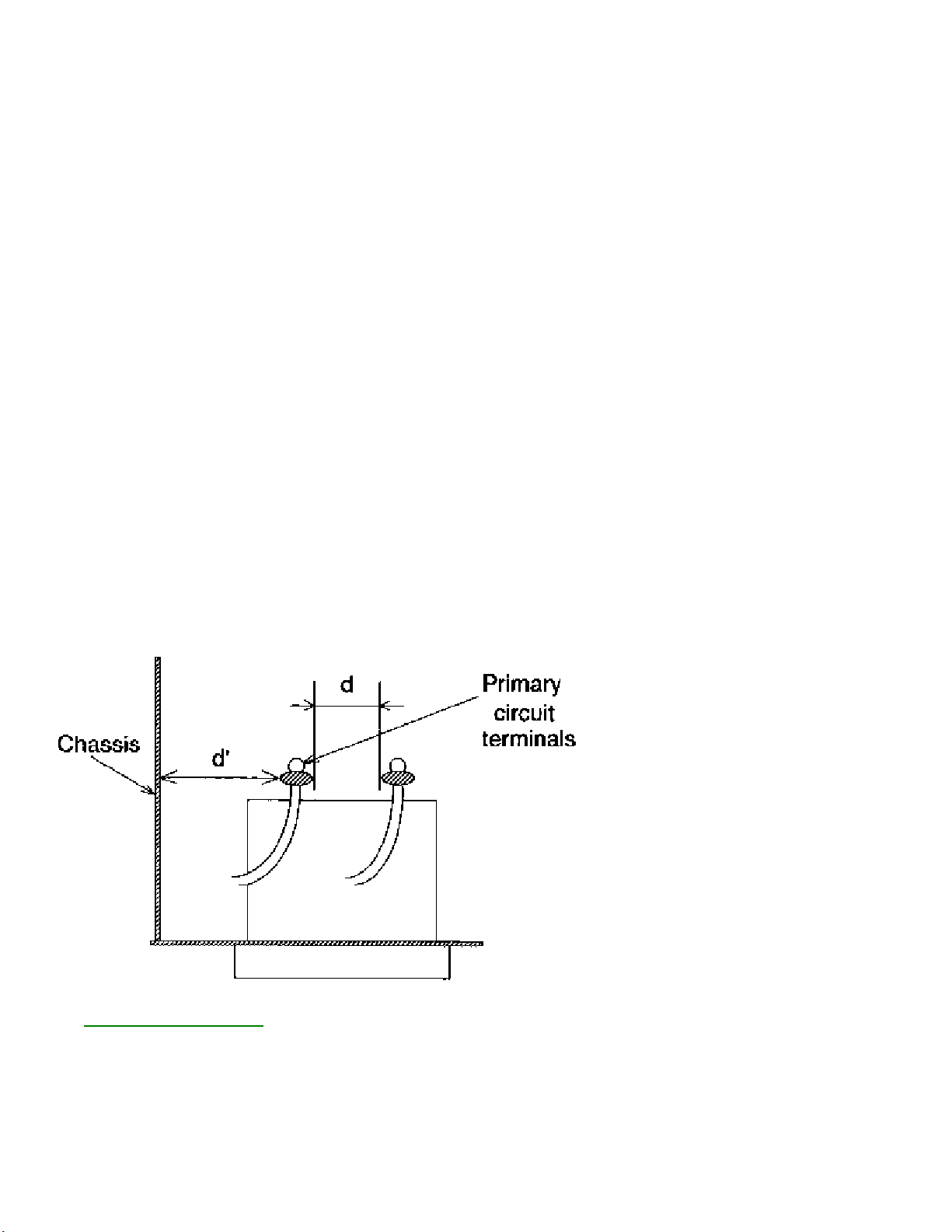
1. Clearance Distance
When replacing primary circuit components, confirm specified clearance distance (d) and (d') between
soldered terminals, and between terminals and surrounding metallic parts. (See graphic bllow)
Table 1 : Ratings for selected area
AC Line Voltage Region Clearance Distance
(d) (d')
USA or > 3.2 mm
110 to 130 V CANADA (0.126 inches)
Note: This table is unofficial and for reference only. Be sure to confirm the precise values.
2. LEAKAGE CURRENT CHECKS

VCR SAFETY NOTES
FIRE & SHOCK HAZARD (VCR)
1. Be sure that all components are positioned in such a way to avoid possibility of shorts to adjacent
components. This is especially important on those chassis which are transported to and from the repair
shop.
2. Always replace all protective devices such as insulators and barriers after working on a set.
3. Check for damaged insulation on wires including the ac cord.
4. Check across-the-line components for damage and replace if necessary.
5. After re-assembly of the unit, always perform an ac leakage test on the exposed metallic parts of the
cabinet such as the knobs, antenna terminals, etc. to be sure the set is safe to operate without danger of
electrical shock. Do not use a line isolation transformer during this test. Use an ac voltmeter
having 5000 ohms per volt or more sensitivity in the following manner: Connect a 1500 ohm 10 wan
resistor, paralleled by 0.15 MFD ac type capacitor, between a known good earth ground (water pipe,
conduit, etc.) and the exposed metallic parts, one at a time. Measure the ac voltage across the
combination 1500 ohm resistor and 0.15 MFD capacitor. Reverse the ac plug on the set and repeat ac
voltage measurements again for each exposed metallic part. Voltage measured must not exceed O.6
volts R.M.S. This corresponds to 0.4 milliamp ac. Any value exceeding this limit constitutes a potential
shock hazard and must be corrected immediately.
GENERAL
Power Supply-This receiver is designed for operation on 120 Volts, 6OHz alternating current (ac) only.
Never connect to a supply having a different frequency or voltage.
IMPORTANT NOTICE
This device employs many circuits, components, and mechanical parts designed for protection against
fire, shock and RF interference. For continued safety any servicing should be performed by qualified
personnel and exact replacement parts should be used. Under no circumstances should the original
design be altered.
PRODUCT SAFETY GUIDELINES FOR ALL PRODUCTS
CAUTION: Do not modify any circuit. Service work should be performed only after you are thoroughly
familiar with all of the following safety checks. Risk of potential hazards and injury to the user increases if
safety checks are not adhered to.
USE A SEPARATE ISOLATION TRANSFORMER FOR THIS UNIT WHEN SERVICING.

PREVENTION OF ELECTROSTATIC DISCHARGE (ESD)
Some semiconductor solid state devices can be damaged easily by static electricity. Such components
commonly are called Electrostatically Sensitive (ES) Devices, Examples of typical ES devices are
integrated circuits and some field-effect transistors and semiconductor "chip" components. The following
techniques should be used to help reduce the incidence of component damage caused by electrostatic
discharge (ESD).
1. Immediately before handling any semiconductor component or semiconductor-equipped assembly,
drain off any ESD on your body by touching a known earth ground. Alternatively, obtain and wear a
commercially available discharging ESD wrist strap, which should be removed for potential shock reasons
prior to applying power to the unit under test.
2. After removing an electrical assembly equipped with ES devices, place the assembly on a conductive
surface such as aluminum foil, to prevent electrostatic charge buildup or exposure of the assembly.
3. Use only a grounded-tip soldering iron to solder or unsolder ES devices.
4. Use only an anti-static solder removal device. Some solder removal devices not classified as "antistatic
(ESD protected)" can generate an electrical charge sufficient to damage ES devices.
5. Do not use freon·propelled chemicals. These can generate electrical charges sufficient to damage ES
devices.
6. Do not remove a replacement ES device from its protective package until immediately before you are
ready to install it (Most replacement ES devices are packaged with leads electrically shorted together by
conductive foam, aluminum foil or comparable conductive material).
7. Immediately before removing the protective material from the leads of a replacement ES device, touch
the protective material to the chassis or circuit assembly into which the device will be installed.
CAUTION : Be sure no power is applied to the chassis or circuit and observe all other safety
precautions.
8. Minimize bodily motions when handling unpackaged replacement ES devices. (Otherwise harmless
motion such as the brushing together of your clothes fabric or the lifting of your feet from a carpeted
floor can generate static electricity (ESD) sufficient to damage an ES device.)
NOTE to CATV system Installer:
This reminder is provided to call the CATV system installer's attention to article 820-22 of the NEC that
provides guidelines for proper grounding and, in particular, specifies that the cable ground shall be
connected to the grounding system of the building, as close to the point of cable entry as practical.

7615 DFU Information
Directions For Use (DFU)
For Customer Operating Instructions, please visit our web site: www.p4c.philips.com.

A10 PTV ADJUSTMENTS
7615 Adjustments page 1
MANUAL 7615
Service Modes and Error Messages
The following topics are covered:
• Test points
• Service Modes
• Error code buffer and error codes
• The “blinking LED” procedure
• Trouble shooting tips
• Customer Service Mode
Measurements should be performed under the following conditions:
Video: color bar signal
Audio: 3kHz left, 1kHz right
Note: The measurements at the following test points were taken using a 100:1 probe:
• I142, LSB Panel
• I220, LSB Panel
Service Default Mode (SDM)
Introduction
The Service Default Mode (SDM) is a technical aid for the service technician. The Service Default Mode
(SDM) establishes fixed, repeatable settings of customer controls, which allow consistent measurements
to be made. The SDM also initiates the blinking LED procedure and, if necessary, overrides the 5V
protection. This mode also allows the operating hours of the set, the software version, and error codes to
be read.
The SDM places the set in the following pre -defined conditions:
• Tuning frequency set to Channel 3.
• Volume level set to 25% (of the maximum volume level).
• Other picture and sound settings set to 50% (mid -range).
The following functions are turned off in SDM (and after leaving SDM):
• Timer
• Sleep timer
The follow ing functions are disabled during SDM (and enabled after leaving SDM):
• Parental lock
All other controls operate normally.
Entering Service Default Mode
7615 Adjustments page 2
To enter the Service Default Mode, press the following key sequence on the remote control transmitter:
0-6-2-5-9-6-MENU
Do not allow the display to time out between entries while keying the sequence.
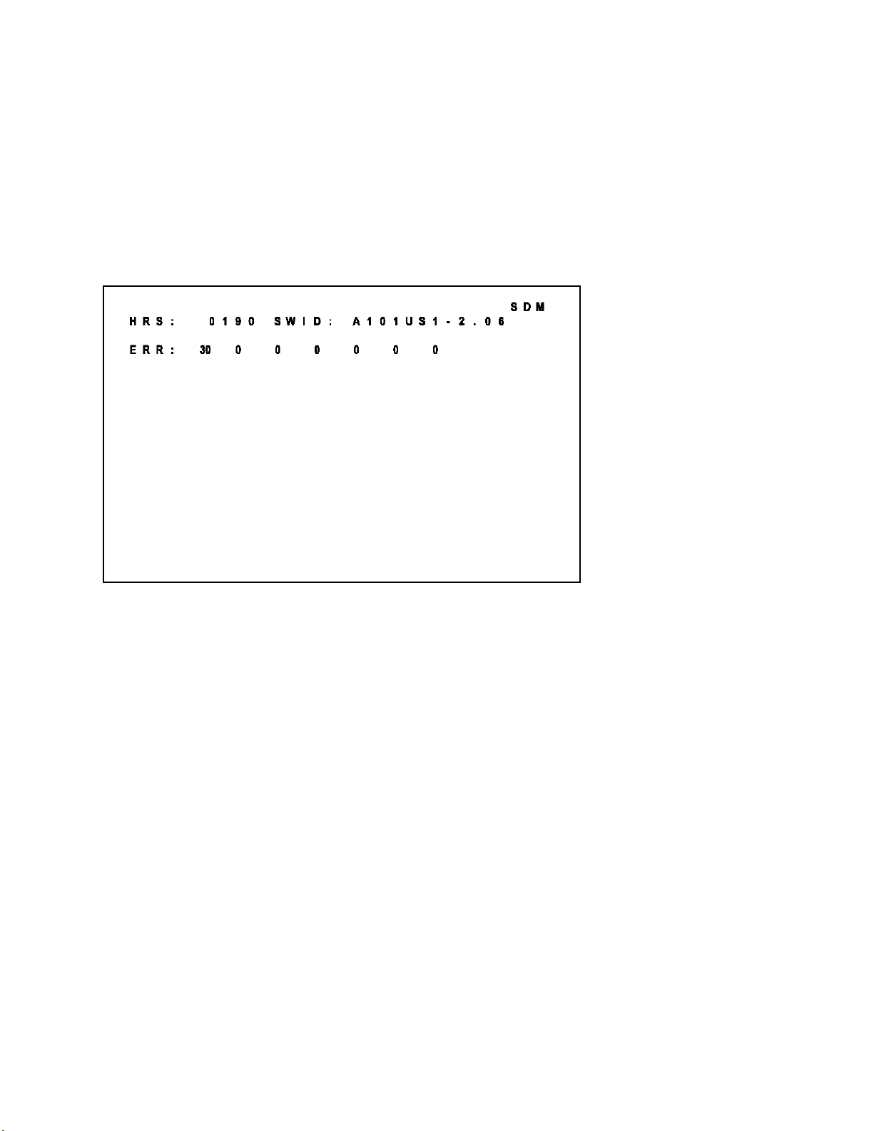
Upon entry into the Service Default Mode, the letters “SDM” will be displayed at the upper right corner of
the screen.
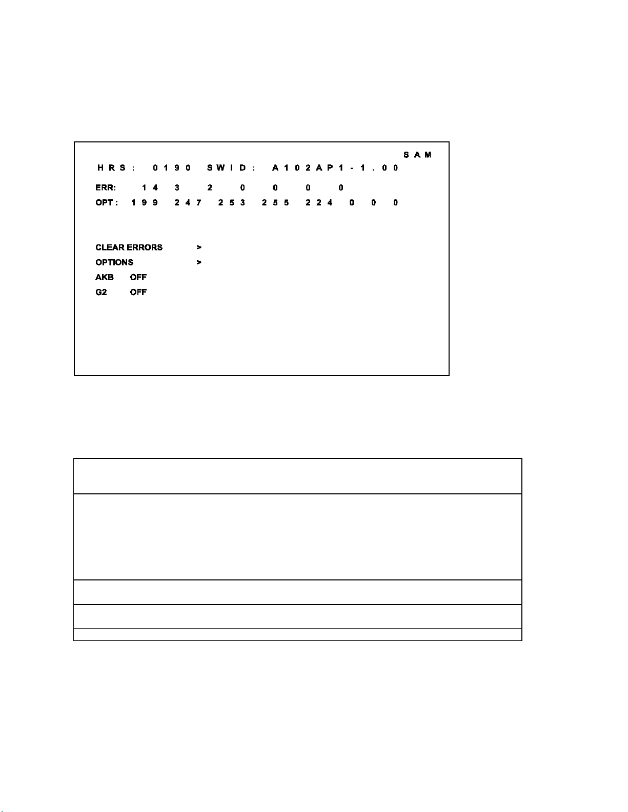
Figure 1: SDM Screen
Special SDM functions
Access to normal user menu
Pressing the “MENU” button on the remote control switches between the SDM and the normal user
menus (with the SDM mode still active in the background).
Run timer, software identification, and error buffer
Press the Index or Status button on the remote control to toggle the OSD (except “SDM”) ON and OFF
to prevent the OSD from interfering with measurements and oscilloscope waveforms.
Access to SAM
To access the Service Alignment Mode while press the “VOLUME +” and “VOLUME –“ buttons on the
local keyboard simultaneously for at least 4 seconds.

The Blinking LED Procedure
7615 Adjustments page 3
The contents of the error buffer can also be made visible through the “blinking LED” procedure. This is
especially useful when there is no picture.
NOTE: If errors 1, 2, 3, or 4 occur the LED ALWAYS blinks indicating the last error which occurred,
even if the set is NOT in service mode.
• When the SDM is entered, the LED will blink the number of times equal to the value of the error code.
Upon entry into the SDM, the LED will blink the contents of the error -buffer.
Error-codes greater than/equal to 10 are shown in the following manner:
A long blink of 750 milliseconds indicating the decimal digit, followed by a pause of 1500 milliseconds.
The LED will then blink the number equal to the error code. When all error-codes are displayed, the
sequence is finished with an LED display of 3 seconds. At this point the sequence will begin again.
Example:
Error code position 1 2 3 4 5
Error buffer: 12 9 6 0 0
• After entering SDM:
• The sequence will begin with 1 long blink of 750 milliseconds, then pause 1500 milliseconds, then
blink twice (indicating error code 12), then the LED will pause for 3 seconds, then blink 9 times
(indicating error code 9), then the LED will pause for 3 seconds, then blink 6 times (indicating error
code 6), then pause 3 seconds and blink for 3 seconds again, ending the blinking sequence.
Exiting Service Default Mode
To exit the Service Default Mod e, press the Power button.
Service Alignment Mode (SAM)
Introduction
The Service Alignment Mode (SAM) is used to align the set and/or adjust the option settings and to
display/clear the error code buffer values.
Entering Service Alignment Mode
To enter the Service Alignment Mode (SAM), press the following key sequence on the remote control
transmitter:
0-6-2-5-9-6-INDEX or STATUS
Do not allow the display to time out between entries while keying the sequence
It is also possible to enter the Service Alignment Mode by pressing the “VOLUME +” and “VOLUME -” key
on the local keyboard simultaneously for at least 4 seconds when the set is in SDM.
Exit SAM:
7615 Adjustments page 4
To exit the Service Alignment Mode, press the Power button.
In SAM the following information is displayed on the screen:
Figure 2: SAM Screen
Explanation notes/references:
1 Operation Hours (Run Timer):
This display indicates the accumulated total of operational hours. (Shown in hexadecimal
format)
2 Software identification of the main micro controller (A101US1-2.06)
A10 is the engineering chassis name for the A10 PTV chassis
• 1US1 is a character combination to indicate the software type and the supported languages:
3AP1 or 3AP2 are also possible in the Asian Pacific Region.
• US = United States, AP = Asian Pacific
• 1 = Main Software language version number
• 2.06 = sub-version number
3 Error buffer (7 errors possible):
Displays the 7 most recent errors. The most recent error is displayed at the upper left.
4 Option bytes (8 codes possible):
Summary of options is explained below.
5 Sub menus are listed in a scroll menu.

SAM Menu Control
7615 Adjustments page 5
Menu items may be selected using the cursor UP/DOWN keys.
• The selected item will be highlighted.
• When not all menu items will fit on the screen, pressing the cursor UP/DOWN keys on the remote
transmitter will display the next/previous menu items.
With the cursor LEFT/RIGHT keys, it is possible to:
• (de)activate the selected menu item (e.g. GEOMETRY)
• change the value of the selected menu item (e.g., VER-SLOPE)
• activate the selected submenu (e.g., SERV -BLK)
Access to normal user menu
Pressing the “MENU” button on the remote control switches between the SAM and the normal user
menus (with the SAM mode still active in the background). Pressing the “MENU” key in a submenu will
return the screen to the previous menu.
The Menus and Submenus
Clear Errors
Erases the contents of the error buffer. Select the CLEA R ERRORS menu item and press the cursor
LEFT or cursor RIGHT key. The contents of the error buffer are cleared.
The functionality of the OPTIONS and ALIGNMENTS (TUNER, WHITE TONE, GEOMETRY, SOUND,
and SMART SETTING) submenus are described in the service adjustments.
Error code buffer and error codes
Explanation of the Error code buffer
The error code buffer contains all errors detected since the last time the buffer was erased. The buffer
is written from left to right. When an error occurs that is not yet in the error code buffer, the error code
will appear at the left side and all other errors shift one position to the right.
The error code buffer will be cleared in the following cases:
• by activating CLEAR ERRORS in SAM menu
• exiting SDM or SAM with the “Standby" command on the remote control
• upon automatic reset when content has not changed for 50 consecutive hours
By leaving SDM or SAM via the power switch, the error buffer will not be reset.
Examples:
ERROR: 0 0 0 0 0 0 0 : No errors detected
ERROR: 6 0 0 0 0 0 0 : Error code 6 is the last and only detected error
ERROR: 9 6 0 0 0 0 0 : Error code 6 was first detected and error code 9 is the last detected (newest)
error
The cont ents of the error buffer can also be displayed by use of the “blinking LED” procedure, if no
picture is available. See explanation of “The blinking LED procedure “below.

Error code definition
7615 Adjustments page 6
In case of non-intermittent faults, clear the error buffer bef ore starting the repair, to make sure “old” error
codes are not present. If possible check the entire content of the error buffers. In some situations an error
code is only the result of another error code (and not the actual cause).
Note: a fault in the protection detection circuitry can also lead to a protection.
Error codes 1,2, 3, and 4 are protection codes, and in this case the supplies of some circuits will be
switched off. Also in protection, the LED will blink the number of times equivalent to the most recent error
code.
Error code table
Code Number Error Description
00 Not an Error
01 Too high I-beam or East/West protection
02 Vertical protection
03 X-Ray protection
04 5 volt protection
05 - not used
06 General IIC error
07 BC loop not stabilized
08 Bocma TDA888X IIC error
09 Bocma IC 8v failure
10 NVM IIC communication error
11 Wrong NVM type
12 Microp internal RAM error
13 Main tuner IIC failure
14 Sound IC failure
15 SRAM test failure
16 PIP Tuner IIC failure
17 ECO Pip IC or DW Pip IC failure
18 I/O expander I2C error
19 Gemstar Guide Plus board
20 V-chip located on the DW Pip
21 Non-Volatile clock
22 Incredible picture (YUV) CR
23 Bocma DoubleWindow TDA888X error
24 - not used
25 - not used
26 - not used
27 Virtual Dolby
28 - not used
29 - not used
30 CSP i2c error
31 CSP NVM i2c error
32 CSP NVM error - not valid data
33 CSP dac i2c error
A10 PTV MODEL LISTINGS AND SOFTWARE
7615 Adjustments page 7
MODEL REGION CHASSIS SOFTWARE
43P8341/37 (USA Model) PTV914, Fighter + 1US1 (see B)
43PP925/61 (Korea Model) - - - - 3AP2 (see D)
43PP925/97 (Taiwan & Philippines Model) - - - - 3AP1 (see D)
50P8341/37 (USA Model) PTV915, Fighter + 1US1 (see B)
50P8342/37 (USA Model, Sears) PTV916, Fighter + 1US1 (see B)
50PP241/76 (LATAM Model) PTV918 1US1 (see C)
55P8241/37 (USA Model) PTV910, Fighter 1US1 (see A)
55P8288/37 (USA Model, Best Buy) PTV910, Fighter 1US1 (see A)
55P8341/37 (USA Model) PTV915, Fighter + 1US1 (see B)
55P8342/37 (USA Model, Sears) PTV916, Fighter + 1US1 (see B)
55PP241/76 (LATAM Model) PTV918 1US1 (see C)
55PP925/61 (Korea Model) - - - - 3AP2 (see D)
55PP925/97 (Taiwan & Philippines Model) - - - - 3AP1 (see D)
60P8241/37 (USA Model) PTV910, Fighter 1US1 (see A)
60P8288/37 (USA Model, Best Buy) PTV910, Fighter 1US1 (see A)
60P8341/37 (USA Model) PTV915, Fighter + 1US1 (see B)
60P8342/37 (USA Model, Sears) PTV916, Fighter + 1US1 (see B)
60PP241/76 (LATAM Model) PTV918 1US1 (see C)
64P8341/37 (USA Model) PTV915, Fighter + 1US1 (see B)
64P8342/37 (USA Model, Sears) PTV916, Fighter + 1US1 (see B)

Option Codes - NAFTA
7615 Adjustments page 8
A = USA Fighter, (1US1 Software)
B = USA Fighter +, (1US1 Software)
C = NAFTA Mexico, (1US1 Software)
1US1 CODE DESCRIPTIONS
SBNP AUTO STANDBY NO PICTURE OFF OFF OFF
CVI COMPONENT VIDEO INPUT ON ON ON
C169 COMPRESS 16:9 MODE AVAILABLE OFF OFF OFF
E149 EXPAND 14:9 MODE AVAILABLE OFF OFF OFF
SMCK SMART CLOCK ON ON ON
AV3 SIDE AV SOURCE OFF ON OFF
CBFL COMB FILTER ON ON ON
IPIX INCREDIBLE PICTURE ON ON ON
IPMU INCREDIBLE PICTURE VIA MENU ITEM ON ON ON
VDBY VIRTUAL DOLBY ENABLED OFF OFF OFF
PLST PROGRAM LIST ON ON ON
SOSD SMART OSD ON ON ON
BLMU BLUE MUTE OFF OFF OFF
PIPC PIP CONTROL ON ON ON
PIPT PIP TUNER OFF ON OFF
VSLC VERTICAL SLICING ON ON ON
SURF SURF FEATURE AVAILABLE ON ON ON
CCAP CLOSED CAPTION ON ON ON
DNRM DNR FUNCTION AVAILABLE ON ON ON
NVCK NON VOLATILE CLOCK OFF OFF ON
VMUT VIDEO BLANKING DURING CHANNEL CH ON ON ON
TIME TIMER FEATURE AVAILABLE ON ON ON
AAVL AVL AVAILABLE ON ON ON
FUNN FINE TUNING MENU ITEM OFF OFF OFF
VCBK V-CHIP BLOCK UNRATED MENU ON ON ON
VBNR V-CHIP BLOCK NO RATED MENU ON ON ON
USRC REMOTE A/B MENU ITEM OFF OFF OFF
BNUM NUMERICS DISPLAYED IN MENUS ON ON ON
ROTI ROTATION/TILT OFF OFF OFF
SNIC SOUND BOARD PRESENT OFF OFF OFF
TMWIN TIMEOUT FOR DIGIT ENTRY ON=5SEC OFF=2SEC OFF OFF OFF
INCF INTERNAL COMB FILTER PRESENT ON ON ON
NVM NVM CORRUPTION ON ON ON
1US1LOW PTV CLUSTER SELECT ON OFF ON
1US1HIGH PTV CLUSTER SELECT OFF ON OFF
CL12 12/24 HOUR CLOCK ON=12 OFF=24 ON ON OFF
HWBMS HARDWARE BLUE MUTE STREAK OFF OFF OFF
OB1 CAN BE USED TO ADJUST OPTION BYTES AT ONCE 75 79 75
OB2 181 183 181
OB3 238 238 255
OB4 209 209 209
OB5 208 176 160
OB6-OB8 0 0 0
A B C

Option Codes - Asia Pacific
7615 Adjustments page 9
D = Taiwan & Philippines, (3AP1 Software)
Korea, (3AP2 Software)
3AP1 & 3AP2 CODE DESCRIPTIONS
ABSY AUTO STANDBY AFTER NO INTERACTION OFF
SBNP AUTO STANDBY NO PICTURE ON
CVI COMPONENT VIDEO INPUT ON
C169 COMPRESS 16:9 MODE AVAILABLE OFF
E149 EXPAND 14:9 MODE AVAILABLE OFF
HWBMS HARDWARE BLUE MUTE STREAK ON
SMCK SMART CLOCK ON
AV3 SIDE AV SOURCE ON
AUSB AUTO STANDBY AUTO ON ON
CBFL COMB FILTER ON
IPIX INCREDIBLE PICTURE ON
IPMU INCREDIBLE PICTURE VIA MENU ITEM ON
VDBY VIRTUAL DOLBY ENABLED ON
PITN PHILIPS TUNER OFF
PLST PROGRAM LIST ON
SOSD SMART OSD ON
BLMU BLUE MUTE OFF
PIPC PIP CONTROL ON
PIPS PIP SURF ON
PIPT PIP TUNER ON
ISUR INCREDIBLE SURROUND ON
W4x3 DOUBLE WINDOW WITH 4:3 MAIN PICTURE AVAILABLE ON
W169 DOUBLE WINDOW TWO COMPRESSED 16:9 AVAILABLE OFF
VSLC VERTICAL SLICING ON
SURF SURF FEATURE AVAILABLE ON
CCAP CLOSED CAPTION ON
DNRM DNR FUNCTION AVAILABLE ON
VMUT VIDEO BLANKING DURING CHANNEL CH ON
TIME TIMER FEATURE AVAILABLE ON
AAVL AVL AVAILABLE ON
CHLK CHILD LOCK FEATURE AVAILABLE ON
ROTI ROTATION/TILT OFF
SNIC SOUND BOARD PRESENT ON
TMWIN TIMEOUT FOR DIGIT ENTRY ON=5SEC OFF=2SEC OFF
INCF INTERNAL COMB FILTER PRESENT ON
NVM NVM CORRUPTION ON
HWBMS HARDWARE BLUE MUTE STREAK OFF
OB1 CAN BE USED TO ADJUST OPTION BYTES AT ONCE 99
OB2 246
OB3 251
OB4 253
OB5 112
OB6-OB8 0
D
Option Codes - Late Production Change
7615 Adjustments page 10
Late Production SSM Panels with HWBMS "ON"
A = USA Fighter, (1US1 Software)
B = USA Fighter +, (1US1 Software)
C = NAFTA Mexico, (1US1 Software)
D = Taiwan & Philippines, (3AP1 Software) - Korea, (3AP2 Software)
HWBMS HARDWARE BLUE MUTE STREAK ON ON ON ON
OB1 CAN BE USED TO ADJUST OPTION BYTES AT ONCE 75 79 75 99
OB2 181 183 181 246
OB3 238 238 255 251
OB4 209 209 209 253
OB5
OB6-OB8 0 0 0 0
A B C D
Gray Scale Alignment
Gray Scale alignment will be necessary after changing the SSB (Small Signal Board) or the CRTs.
Enter the Service Alignment Mode by entering 0-6-2-5-9-6-(Status or Index).
G2 Setup
Preferred Method
1. Connect a Blac k Level signal to the set.
2. Preset all G2 controls on the Focus/G2 Combo Block to minimum (fully CCW)
3. Connect an Oscilloscope to the Collector of each output transistor on the Green CRT board. Set the
probe to times 10.
4. Adjust the Green G2 control until the Black Level is at 200V.
5. Repeat steps 3 and 4 for the Red and Blue CRTs.
Alternate Method
1. Connect a Black Level signal to the set.
2. Preset all G2 controls on the Focus/G2 Combo Block to minimum (fully CCW).
3. Turn each G2 control clockwise until each CRT is barely illuminated.

Gray Scale Setup
7615 Adjustments page 11
1. Connect a Gray Scale pattern to the set.
2. Preset the registers as shown below.
NORMAL RED 26
NORMAL GREEN 56
NORMAL BLUE 59
NORMAL BLACK LEVEL RED 10
NORMAL BLACK LEVEL GREEN 13
DELTA COOL RED -6
DELTA COOL GREEN -7
DELTA COOL BLUE 4
DELTA COOL BLACK LEVEL RED 2
DELTA COOL BLACK LEVEL GREEN 1
DELTA WARM RED 6
DELTA WARM GREEN 0
DELTA WARM BLUE -8
DELTA WARM BLACK LEVEL RED -2
DELTA WARM BLACK LEVEL GREEN -1
CATHODE DR 12
3. Set Brightness, Color, and Sharpness controls to 40 and Picture control to maximum.
4. Adjust the NORMAL BLACK LEVEL controls to set the correct gray scale in the dark areas of the
picture.
5. Adjust the NORMAL RED AND BLUE controls to set the correct gray scale in the light areas of the
picture.
6. Use the Menu button on the Remote to back out to the main service menu.
7. Turn the set off using the Power Button on the Remote or the front of the set.
Customer Service Mode (CSM)
All PTV900 series sets are equipped with the “Customer Service Mode” (CSM). CSM is a special service
mode that can be activated and deactivated by the customer, by request of the service technician/dealer
in order to identify the status of the set. This CSM is a 'read only' mode, therefore modifications in this
mode are not possible.

Entering the Customer Service Mode
7615 Adjustments page 12
The Customer Service Mode can be switched on:
• By pressing the MUTE button on the remote control and any key on the local keyboard (Channel Up,
Channel Down, VOL +, VOL -) on the TV simultaneously for at least 4 seconds.
The following menu will appear.
Figure 3: CSM Screen
When the CSM is activated:
• picture and sound settings are set to nominal levels
• Modes that interfere with the behavior of the set are switched off (s leep timer, auto standby, etc.)
Exit the Customer Service Mode
The Customer Service Mode will be switched off after:
• Pressing any key on the remote control (except “Channel Up” or “Channel Down”)
• Switching off the TV set by pressing the Power button on the remote control or the local keyboard.
Exiting CSM resets the TV set back to its initial values.
The Customer Service Mode Information Screen
7615 Adjustments page 13
Upon entry into the Customer Service Mode the following screen will appear.
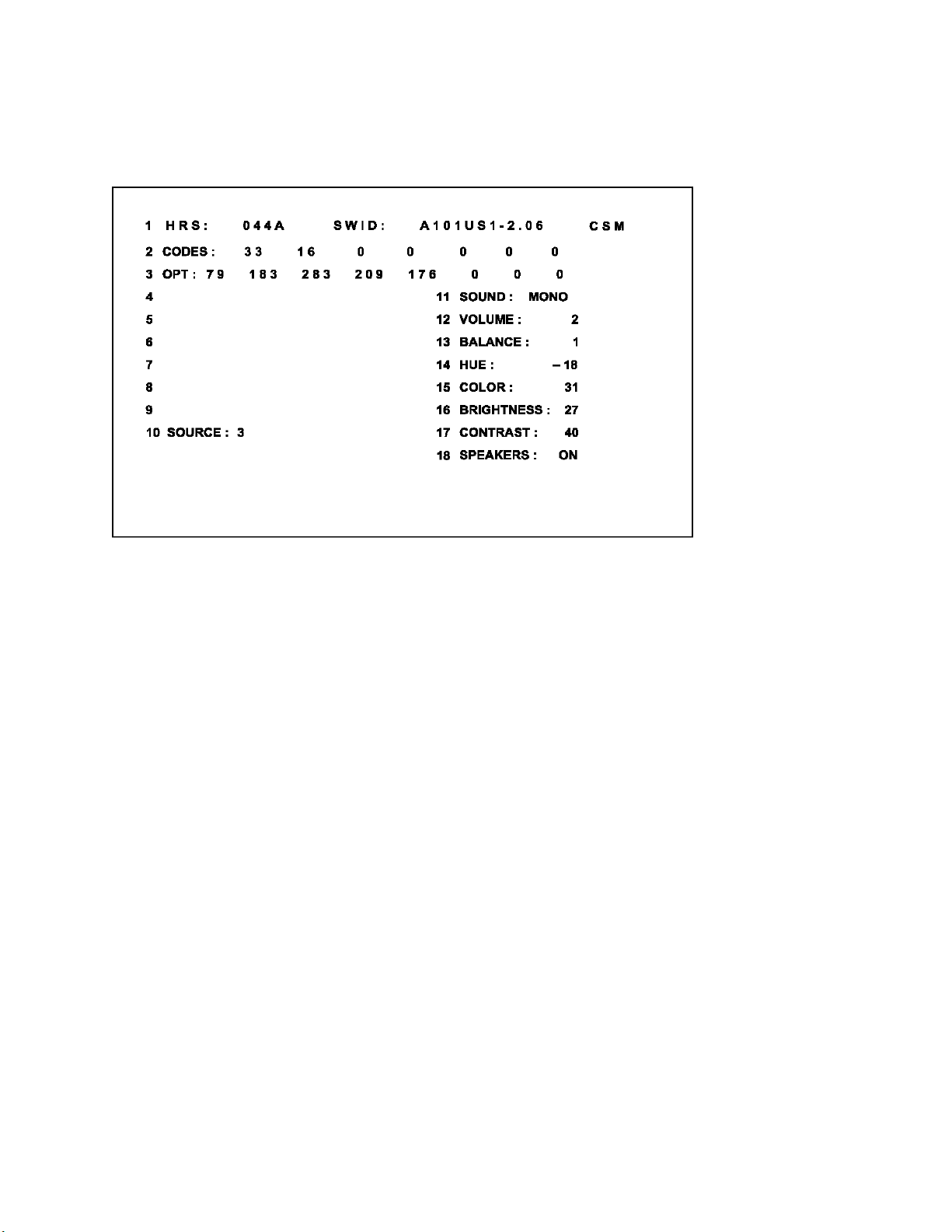
Figure 4: CSM Screen
The Customer Service Menu shows the following information:
- Line 1: “HRS : nnnnn” and SWID : “A10BBC-X.Y”
HRS:
Indicates the accumulated total of operational hours. (Shown in hexadecimal format.) (Standby hours are
not counted as operating hours).
SWID:
Software identification of the main micro controller (example: A10US1-2.7)
A10 is the engineering chassis name for the PTV900 series chassis
· 1US1 is character combination to indicate the software type and the supported languages:
3AP1 or 3AP2 are also possible for the Asian Pacific regions.
· US = USA/NAFTA, AP = Asian Pacific
· 1 = Main Software language version number
· 2.7 = sub-version number
- Line 2: “CODES: xx xx xx xx xx xx xx ”
Error code buffer (see explanation of error codes above) Displays the last 7 errors of the error code
buffer.
- Line 3: “OPT xxx xxx xxx xxx xxx xxx xxx xxx”
Option bytes
Option bits control the software and hardware functionality of the A10.0. An option byte or option number
represents 8 of those bits. Each option number is displayed as a number between 0 and 255. The set
may not work correctly when an incorrect option code is set. See Service Adjustments for more
information on correct option settings

- Line 4: NOT USED
7615 Adjustments page 14
- Line 5: “NO SIGNAL”
Indicates that the set is not receiving an “ident” signal on the selected source.
· no or bad antenna signal; connect a proper antenna signal
· antenna not connected; connect the antenna
· no channel / preset is stored at this program number; go to the INSTALL menu and stor e a proper
channel at this program number
· the tuner is faulty (in this case the CODES line will contain number 13 or 16); check the tuner and
replace/repair if necessary
Note: On some models, (if the BM option is ON), BLUE MUTE is displayed when no signal is
received.
- Line 6: “TIMER ON ”
Indicates that the on/off timer is running.
The following Complaints may be caused by the activation of the sleep timer:
The set may turn on from standby or may switch to a different channel without using either the remote
control or the local keyboard.
To switch off the activation timer:
Select “TIMER” in the “FEATURE” menu.
Select “ACTIVATE’ in the “TIMER” menu.
Set to “OFF” with the left/right cursor keys.
- Line 7: NOT AVAILABLE
- Line 8: “NOT PREFERRED”
Indicates that at least one channel is deleted as a preferred channel (by default, all channels are skipped.
Note that “SKIPPED” will always be displayed in CSM unless all the channels are not skipped.
To add a channel as a selected channel to the list of preferred channels:
Select “INSTALL” menu
Select “CHANNEL EDIT”
Select “ADD/DELETE”
Set to “ADD” with the left/right cursor keys
- Line 9: “HOTEL MODE ON”
Indicates that the Hotel mode has been activated.
- Line 10: “SOURCE:”
Indicates which SOURCE is installed for this preset.
EXT1, SVHS2, EXT2, Tuner.
- Line 11: “SOUND”
Indicates which sound mode is installed for this preset.
Mono, NICAM, Stereo, L1, L2, SAP, Virtual or Digital
- Line 12: “VOLUME”
Value indicates level at entry CSM.
- Line 13: “BALAN CE”
Value indicates level at entry CSM.

- Line 14: “HUE”
7615 Adjustments page 15
Value indicates level at entry CSM.
- Line 15: “COLOR”
Value indicates level at entry CSM.
- Line 16: “BRIGHTNESS”
Value indicates level at entry CSM.
- Line 17: “CONTRAST”
Value indicates level at entry CSM.
- Line 18: "SPEAKERS"
Indicates is the Speakers are On or Off.
Convergence Procedures
The set should be warmed up for at least 20 minutes prior to making any Geometry or Convergence
adjustments.
A signal must be applied to the set while performing Convergence or Geometry alignments. This is
necessary to provide the correct horizontal and vertical sync to the Convergence panel. Failure to do so
will result in an out of convergence picture when signal is applied to the set.
The Serviced Technician should sit at least 5 to 10 feet from the front of the screen while doing
Convergence. Ensure that you are eye level with the area of the screen you are adjusting.
When performing Digital Convergence, the adjustments are interactive. A change in one quadrant will
affect adjacent areas of the screen. Several passes through the Convergence sequence may be
necessary. When doing Convergence, it is advised to follow the sequence pattern when going from on
adjustment location to another. Pressing the Right Cursor key will sequence the Icon through a preloaded
sequence.
When the Convergence error is small, a touch up Convergence will be all that is necessary. Do not adjust
Green Geometry while in this mode. A compete in -depth Convergence is required when the Small Signal
Module (SSM) or the Convergence Memory IC, has been replaced. If the SSB (Small Signal Board) or
the Large Signal Board (LSB) has been replaced, a complete in -depth Geometry should be completed
before Convergence is adjusted. The Geometry alignment should not be necessary if the SSB or LSB
have not been changed.
Screen Templates
When performing a complete in -depth Convergence alignment, a Screen Template is necessary to obtain
the correct Geometry. The correct Templates are listed below:
43 INCH ST4168
50 INCH ST4169
55 INCH ST4170
60 INCH ST4171
64 INCH ST4172

Touch-up Convergence adjustments
7615 Adjustments page 16
Enter the Digital Convergence Mode (DCM) by entering 0-6-2-5-9-7-(Status or Index) on the Remote
control. The following menu will appear:
Select an active channel or Aux Input. A signal must be applied to the set when performing convergence.
If any Customer Adjustments need to be made, the Menu button can be used to toggle between the
Customer Menu and DCM. The MPOSD ADJUST is used to center the Customer Convergence grid. A
highlighted cross will appear along with the Convergence alignment grid. The highlighted cross should be
centered onto the center of the Convergence grid.
To perform a Touch Up Convergence, highlight SELECTION and press the right cursor button on the
remote. The following menu will appear:
Selections STORE, RESTORE FACTORY, and RESTORE DEFAULT are not shown after selecting
SELECTION. Press the cursor down button on the Remote for these selections to appear. RESTORE
FACTORY loads Convergence defaults from the Factory Loaded section of the Convergence Memory IC.
RESTORE DEFAULT loads Convergence defaults from the sets software.
To perform a Touch-up Convergence:
1. Enter the Convergence Mode and select RED TO GRE EN or BLUE TO GREEN. Do not select
GREEN (Green Geometry) without placing a Template over the screen. To perform Green
Geometry, refer to the Complete in -depth Convergence.
2. Use the Cursor buttons on the Remote to Navigate from one adjustment point to another. Press the
Status or Index button on the Remote to select ADJUST. Use the cursor buttons on the Remote to
adjust the Red to Green or Blue to Green. Press the Status or Index button again to navigate to the
next adjustment location.
3. After Converg ence alignments are complete, press the Menu button on the Remote to return to the
SELECTION menu.
4. Highlight the STORE selection and press the right cursor key on the Remote to save changes.
5. Use the GREEN TO RED or GREEN TO BLUE selections to perform convergence when the Green
CRT has been replaced.
Complete in-depth Convergence
SCREEN CENTERING
1. Make sure a signal is applied to the set.
2. Enter the Convergence mode by entering 0-6-2-5-9-7-(Status or Index). Select an active channel or
input. If the Customer settings need to be adjusted, pressing the Menu button will access the
Customer menu.
3. Place a Template over the screen.
4. Select GREEN in the SELECTION menu.
5. Place a jumper across connector 1005 on the SSM to defeat convergence drive.
6. Using the centering rings on the Green CRT, center the convergence pattern onto the center point of
the Convergence Template.
7. Press the Menu button on the Remote to return to the SELECTION menu.
8. Select RED TO GREEN in the menu.
9. Center the Red pattern onto the Green pattern.
10. Select BLUE TO GREEN in the SELECTION menu.
11. Center the Blue pattern onto the Green pattern.
12. Remove the Jumper on connector 1005.
Note: If a CRT has been replaced, it is only necessary to perform Screen Centering for the CRT being replaced.
 Loading...