

Page 1
TQBJ 0115-2
LCD Projector
Operating Instructions
Model No. PT-AE300U
PT-AE200U
R
P
C
POWER
LIGHT
INPUT
ENTER
MENU
FREEZE
NORMAL
ASPECT
USER
MEMORY
VOLUME
PICTURE
MODE
SD
MUTE
SD TIME
MENU
LCD PROJECTOR
V
I
D
E
O
C
M
P
N
T
COMPONENT
KEYSTONE
Before operating this product, please read the instructions carefully and save this
manual for future use.
For assistance, please call : 1-888-View-PTV(843-9788)
or send e-mail to : [email protected]
or visit us at www.panasonic.com (U.S.A)
For assistance, please call : 787-750-4300
or visit us at www.panasonic.co.jp/global/ (Puerto Rico)
ENGLISH
Page 2
2-ENGLISH ENGLISH-3
Preparation
CAUTION: This equipment is equipped with a
three-pin grounding-type power
plug. Do not remove the grounding
pin on the power plug. This plug will
only fit a grounding-type power
outlet. This is a safety feature. If you
are unable to insert the plug into the
outlet, contact an electrician. Do not
defeat the purpose of the grounding
plug.
WARNING:
This equipment has been tested and found to comply with the limits for a
Class B digital device, pursuant to Part 15 of the FCC Rules. These limits
are designed to provide reasonable protection against harmful interference
in a residential installation. This equipment generates, uses, and can
radiate radio frequency energy and, if not installed and used in accordance
with the instructions, may cause harmful interference to radio
communications. However, there is no guarantee that interference will not
occur in a particular installation. If this equipment does cause harmful
interference to radio or television reception, which can be determined by
turning the equipment off and on, the user is encouraged to try to correct
the interference by one or more of the following measures:
– Reorient or relocate the receiving antenna.
– Increase the separation between the equipment and receiver.
– Connect the equipment into an outlet on a circuit different from that to
which the receiver is connected.
– Consult the dealer or an experienced radio/TV technician for help.
CAUTION: Any unauthorized changes or modifications to this equipment
will void the users authority to operate.
Do not remove
Declaration of Conformity
Model Number: PT-AE300U / PT-AE200U
Trade Name: Panasonic
Responsible party: Matsushita Electric Corporation of America.
Address: One Panasonic Way Secaucus New Jersey 07094
Telephone number: 1-888-View-PTV(843-9788)
This device complies with Part 15 of the FCC Rules, Operation is subject to
the following two conditions: (1) This device may not cause harmful
interference, and (2) this device must accept any interference received,
including interference that may cause undesired operation.
IMPORTANT SAFETY NOTICE
WARNING:
TO REDUCE THE RISK OF FIRE OR ELECTRIC SHOCK, DO
NOT EXPOSE THIS PRODUCT TO RAIN OR MOISTURE.
Dear Panasonic Customer:
This instruction booklet provides all the necessary operating information that
you might require. We hope it will help you to get the most performance out
of your new product, and that you will be pleased with your Panasonic LCD
projector.
The serial number of your product may be found on its back. You should
note it in the space provided below and retain this booklet in case service is
required.
Model number: PT-AE300U / PT-AE200U
Serial number:
The lightning flash with arrowhead symbol, within an
equilateral triangle, is intended to alert the user to the
presence of uninsulated “dangerous voltage” within the
product’s enclosure that may be of sufficient magnitude to
constitute a risk of electric shock to persons.
The exclamation point within an equilateral triangle is
intended to alert the user to the presence of important
operating and maintenance (servicing) instructions in the
literature accompanying the product.
Power Supply: This LCD Projector is designed to operate on 100 V – 240 V, 50 Hz/60
Hz AC, house current only.
CAUTION: The AC power cord which is supplied with the projector as an accessory can
only be used for power supplies up to 125 V, 7 A. If you need to use higher
voltages or currents than this, you will need to obtain a separate 250 V
power cord. If you use the accessory cord in such situations, fire may result.
Page 3

ENGLISH-5
Preparation
Precautions with regard to safety
WARNING
If a problem occurs (such as no image or no sound) or if you notice
smoke or a strange smell coming from the projector, turn off the power
and disconnect the power cord from the wall outlet.
B Do not continue to use the projector in such cases, otherwise fire or
electric shocks could result.
B Check that no more smoke is coming out, and then contact an Authorized
Service Center for repairs.
B Do not attempt to repair the projector yourself, as this can be dangerous.
Do not look into the lens while the projector is being used.
B Strong light is emitted from the projector’s lens. If you look directly into this
light, it can hurt and damage your eyes.
Be especially careful not to let young children look into the lens.
In addition, turn off the power when you are away from the projector.
Do not install this projector in a place which is not strong enough to
take the full weight of the projector.
B If the installation location is not strong enough, it may fall down or tip over,
and severe injury or damage could result.
Installation work (such as ceiling suspension) should only be carried
out by a qualified technician.
B If installation is not carried out correctly, there is the danger that injury or
electric shocks may occur.
If foreign objects or water get inside the projector, or if the projector is
dropped or the cabinet is broken, turn off the power and disconnect the
power cord from the wall outlet.
B Continued use of the projector in this condition may result in fire or electric
shocks.
B Contact an Authorized Service Center for repairs.
Do not overload the wall outlet.
B If the power supply is overloaded (for example, by using too many
adapters), overheating may occur and fire may result.
Do not remove the cover or modify it in any way.
B High voltages which can cause fire or electric shocks are present inside
the projector.
B For any inspection, adjustment and repair work, please contact an
Authorized Service Center.
Clean the power cord plug regularly to prevent it from becoming
covered in dust.
B If dust builds up on the power cord plug, the resulting humidity can
damage the insulation, which could result in fire. Pull the power cord out
from the wall outlet and wipe it with a dry cloth.
4-ENGLISH
Contents
Preparation
IMPORTANT SAFETY NOTICE..........2
Precautions with regard to safety ....5
Accessories........................................9
Precautions on handling .................10
Location and function of each part
...12
Using the remote control unit.........17
Inserting the batteries .....................17
Operating range..............................17
Connections .....................................18
Notes on connections .....................18
Example of connecting to video equipment
...18
Example of connecting to equipment
compatible with YPBPR(CBCR) signals
...19
Example of connecting to computer
...20
Setting-up .........................................21
Projection methods.........................21
Projector position............................21
Basic Operation
Starting to use..................................22
Turning on the power......................22
Turning off the power......................23
On-screen menus.............................24
Menu screens .................................24
Menu operation guide.....................26
Unavailable on-screen menu items
...26
Returning to the previous screen....26
Returning a setting to the factory default
...27
Using the freeze function ................27
Correcting keystone distortion.......28
Setting the ASPECT.........................30
Selecting the picture mode .............32
Using the shutter function ..............33
Changing the display language......33
Muting the sound .............................33
Adjusting the picture .......................34
PICTURE MODE ............................34
CONTRAST....................................34
BRIGHT ..........................................34
COLOR...........................................34
TINT................................................35
SHARPNESS .................................35
TV SYSTEM ...................................35
Color Hue Setting ..........................35
WHITE BALANCE R/G/B ...............36
SIGNAL MODE...............................36
GAMMA ADJUST ..........................36
MEMORY SAVE ............................36
MEMORY LOAD ............................36
Projecting sRGB compatible pictures
...37
Adjusting the position .....................38
HORIZONTAL POSITION ..............38
VERTICAL POSITION....................38
DOT CLOCK...................................38
CLOCK PHASE ..............................38
ASPECT .........................................39
AUTO SETUP.................................39
Advanced Operation
Option settings.................................39
OSD................................................39
NR (Noise Reduction).....................39
PC PRIORITY.................................39
BACK COLOR ................................39
4:3 H-POS ......................................40
FRONT/REAR ................................40
DESK/CEILING ..............................40
FAN CONTROL..............................40
LAMP POWER ...............................40
LAMP RUNTIME ............................40
SD memory card ..............................41
What is the SD memory card?........41
Data that can be played back .........41
Note when using SD memory cards
...41
Inserting and removing the SD
memory card .................................42
About the SD menu..........................43
Playing back still images ................44
Slide playback of still images .........45
Playing back moving images..........49
Error displays...................................50
Others
Indicators..........................................51
Cleaning and replacing
the air filter ....................................53
Replacing the lamp unit ..................54
Before calling for service ................57
Specifications...................................59
Appendix...........................................61
List of compatible signals ...............61
Connector pin wiring.......................62
DCF standard .................................64
Projection dimensions calculation methods
...65
Dimensions.......................................65
Trademark acknowledgements ......66
Page 4

ENGLISH-7
Preparation
6-ENGLISH
B Heated air comes out of the air outlet port. Do not bring your hands or
face, or objects which cannot withstand heat close to this port, otherwise
burns or damage could result.
Replacement of the lamp unit should only be carried out by a qualified
technician.
B The lamp unit has high internal pressure. It can easily become damaged if
struck against hard objects or dropped, and injury or malfunctions may
result.
When replacing the lamp, allow it to cool for at least one hour before
handling it.
B The lamp cover gets very hot, and contact with it can cause burns.
Before replacing the lamp, be sure to unplug the power cord from the
power outlet.
B Electric shocks or explosions can result if this is not done.
Caution
Do not cover the air inlet or the air outlet.
B Doing so may cause the projector to overheat, which can cause fire or
damage to the projector.
Do not set up the projector in humid or dusty places or in places where
the projector may come into contact with smoke or steam.
B Using the projector under such conditions may result in fire or electric
shocks.
When disconnecting the power cord, hold the plug, not the cord.
B If the power cord itself is pulled, the cord will become damaged, and fire,
short-circuits or serious electric shocks may result.
Always disconnect all cables before moving the projector.
B Moving the projector with cables still attached can damage the cables,
which could cause fire or electric shocks to occur.
Do not place any heavy objects on top of the projector.
B Failure to observe this may cause the projector to become unbalanced
and fall, which could result in damage or injury.
Do not short-circuit, heat or disassemble the battery or place it into
water or fire.
B Failure to observe this may cause the battery to overheat, leak, explode or
catch fire, and burns or other injury may result.
When inserting the battery, make sure the polarities (+ and -) are
correct.
B If the battery is inserted incorrectly, it may explode or leak, and fire, injury
or contamination of the battery compartment and surrounding area may
result.
B If not using the projector for an extended period of time, pull the power
cord plug out from the wall outlet.
Do not do anything that might damage the power cord or the power
cord plug.
B Do not damage the power cord, make any modifications to it, place it near
any hot objects, bend it excessively, twist it, pull it, place heavy objects on
top of it or wrap it into a bundle.
B If the power cord is used while damaged, electric shocks, short-circuits or
fire may result.
B Ask an Authorized Service Center to carry out any repairs to the power
cord that might be necessary.
Do not handle the power cord plug with wet hands.
B Failure to observe this may result in electric shocks.
Insert the power cord plug securely into the wall outlet.
B If the plug is not inserted correctly, electric shocks or overheating could
result.
B Do not use plugs which are damaged or wall outlets which are coming
loose from the wall.
Do not place the projector on top of surfaces which are unstable.
B If the projector is placed on top of a surface which is sloped or unstable, it
may fall down or tip over, and injury or damage could result.
Do not place the projector into water or let it become wet.
B Failure to observe this may result in fire or electric shocks.
Do not place liquid containers on top of the projector.
B If water spills onto the projector or gets inside it, fire or electric shocks
could result.
B If any water gets inside the projector, contact an Authorized Service
Center.
Do not insert any foreign objects into the projector.
B Do not insert any metal objects or flammable objects into the projector or
drop them onto the projector, as doing so can result in fire or electric
shocks.
Do not allow the + and - terminals of the battery to come into contact
with metallic objects such as necklaces or hairpins.
B Failure to observe this may cause the battery to leak, overheat, explode or
catch fire.
B Store the battery in a plastic bag and keep it away from metallic objects.
During a thunderstorm, do not touch the projector or the cable.
B Electric shocks can result.
Do not use the projector in a bath or shower.
B Fire or electric shocks can result.
Do not bring your hands or other objects close to the air outlet port.
Page 5
ENGLISH-9
Preparation
8-ENGLISH
Use only the specified battery.
B If an incorrect battery is used, it may explode or leak, and fire, injury or
contamination of the battery compartment and surrounding area may
result.
Do not mix old and new batteries.
B If the batteries are inserted incorrectly, they may explode or leak, and fire,
injury or contamination of the battery compartment and surrounding area
may result.
Do not put your weight on this projector.
B You could fall or the projector could break, and injury may result.
B Be especially careful not to let young children climb onto the equipment.
Disconnect the power cord plug from the wall outlet as a safety
precaution before carrying out any cleaning.
B Electric shocks can result if this is not done.
Ask an Authorized Service Center to clean inside the projector at least
once a year.
B If dust is left to build up inside the projector without being cleaned out, it
can result in fire or problems with operation.
B It is a good idea to clean the inside of the projector before the season for
humid weather arrives. Ask your nearest Authorized Service Center to
clean the projector when required. Please discuss with the Authorized
Service Center regarding cleaning costs.
We are in effort to hold your environment clean. Please bring the non
repairable unit your Dealer or a Recycling Company.
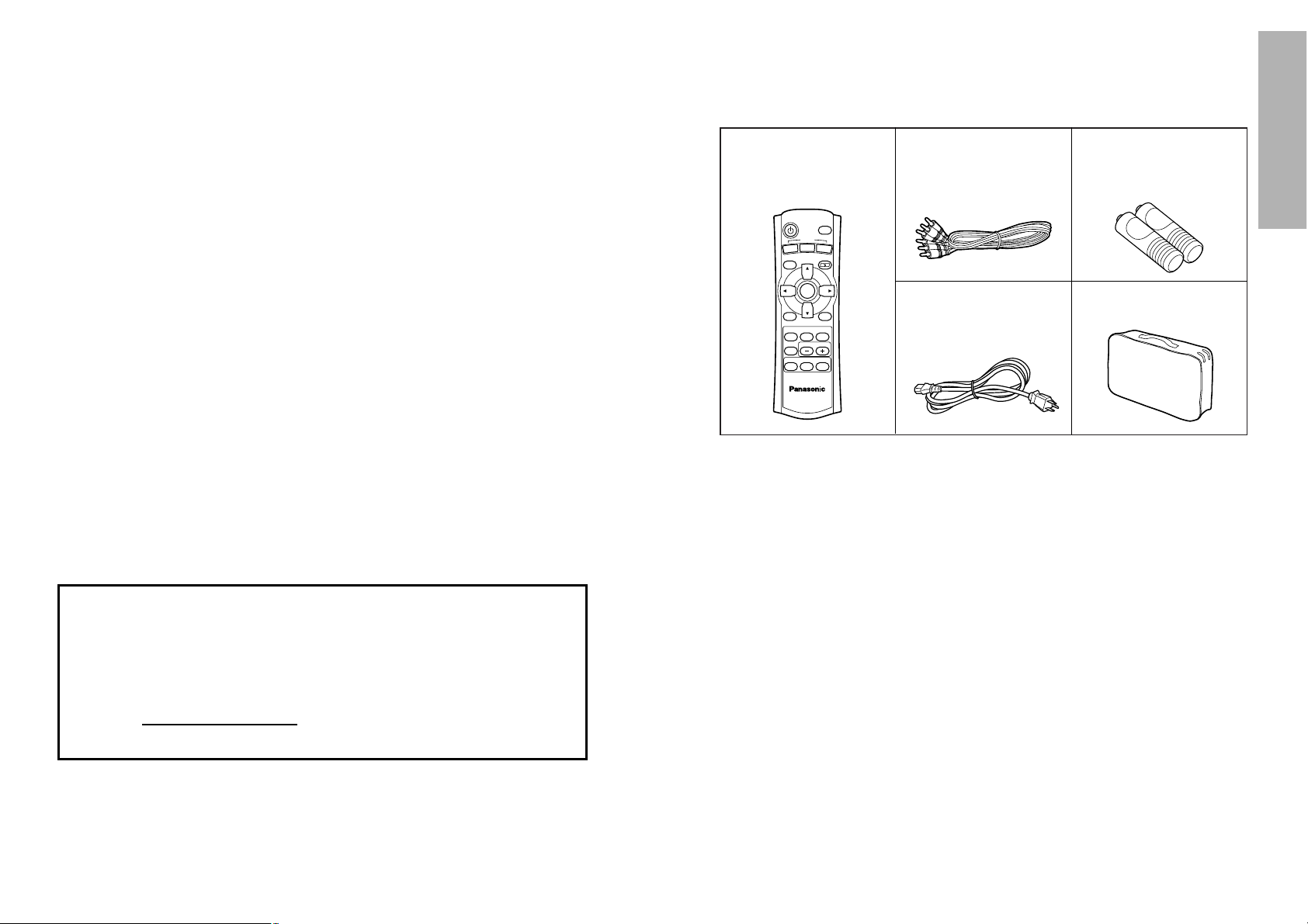
Remote control unit
(N2QAFA000002 x1)
Power cord
(K2CG3FR00001 x 1)
Video/Audio cable [3.0
m (9´10˝),
K2KA2FA00002 x1]
AAA batteries for
remote control unit (x2)
Accessories
Check that all of the accessories shown below have been included with your
projector.
P
C
POWER
LIGHT
INPUT
ENTER
MENU
FREEZE
NORMAL
ASPECT
USER
MEMORY
VOLUME
PICTURE
MODE
SD
MUTE
SD TIME
MENU
LCD PROJECTOR
V
I
D
E
O
C
M
P
N
T
COMPONENT
KEYSTONE
Carrying bag
(TPEP008 x1)
NOTICE:
B This product has a High Intensity Discharge (HID) lamp that contains a
small amount of mercury. It also contains lead in some components.
Disposal of these materials may be regulated in your community due to
environmental considerations. For disposal or recycling information
please contact your local authorities, or the Electronics Industries
Alliance: <http://www.eiae.org.>
Page 6

ENGLISH-11
Preparation
10-ENGLISH
About the SD memory card slot
Make sure that there are no foreign objects inside the slot when inserting an
optional SD memory card. Failure to observe it may damage the card and
the slot.
About the screen
If the screen you are using is dirty, damaged or discolored, attractive
projections cannot be obtained. Do not apply any volatile substances to the
screen, and do not let it become dirty or damaged.
About the lamp
The lamp may need to be replaced earlier due to variables such as a
particular lamp’s characteristics, usage conditions and the installation
environment, especially when it is subjected to a continuous use for more
than 10 hours.
About the liquid crystal panel
The liquid crystal panel of the projector is built with very high precision
technology giving you fine picture details. Occasionally, a few non-active
pixels may appear on the screen as a fixed point of blue, green or red.
Please note that this does not affect the performance of your LCD.
Before carrying out cleaning and maintenance, be
sure to disconnect the power cord plug from the
wall outlet.
Wipe the cabinet with a soft, dry cloth.
If the cabinet is particularly dirty, soak the cloth in water with a small amount
of neutral detergent in it, squeeze the cloth very well, and then wipe the
cabinet. After cleaning, wipe the cabinet dry with a dry cloth.
If using a chemically-treated cloth, read the instructions supplied with
the cloth before use.
Do not wipe the lens with a cloth that is dusty or which produces lint.
If any dust or lint gets onto the lens, such dust or lint will be magnified and
projected onto the screen. Use a blower to clean any dust and lint from the
lens surface, or use a soft cloth to wipe off any dust or lint.
Precautions on handling
Cautions when moving the projector
Be sure to attach the lens cover before moving the projector.
The projection lens is extremely susceptible to vibration and shocks. When
moving the projector, use the accessory carrying bag. When placing the
projector inside the carrying bag, position it so that the lens is facing upward.
Cautions regarding setting-up
Observe the following at all times when setting up the projector.
Avoid setting up in places which are subject to vibration or shocks.
If the projector is set up in locations with strong vibration, such as near a
motor, or if it is installed inside a vehicle or on board a ship, the projector
may be subjected to vibration or shocks which can damage the internal parts
and cause malfunctions or accidents. Accordingly, set up the projector in a
place which is free from such vibrations and shocks.
Do not set up the projector near high-voltage power lines or near
motors.
The projector may be subject to electromagnetic interference if it is set up
near high-voltage power lines or motors.
If installing the projector to the ceiling, ask a qualified technician to
carry out all installation work.
If the projector is to be suspended from the ceiling, you will need to purchase
the separate installation kit (Model No.: ET-PKE300). Furthermore, all
installation work should only be carried out by a qualified technician.
If using this projector at high elevations (above 1400 m), set the FAN
CONTROL to HIGH. (Refer to page 40.)
Failure to observe this may result in malfunctions.
Notes on use
In order to get the best picture quality
If outside light or light from indoor lamps is shining onto the screen, the
images projected will not have good contrast. Draw curtains or blinds over
any windows and turn off any fluorescent lights near the screen to prevent
reflection.
Do not touch the surfaces of the lens with your bare hands.
If the surface of the lens becomes dirty from fingerprints or anything else, this
will be magnified and projected onto the screen. Moreover, when not using
the projector, retract the lens and then cover it with the accessory lens cover.
Page 7
ENGLISH-13
Preparation
12-ENGLISH
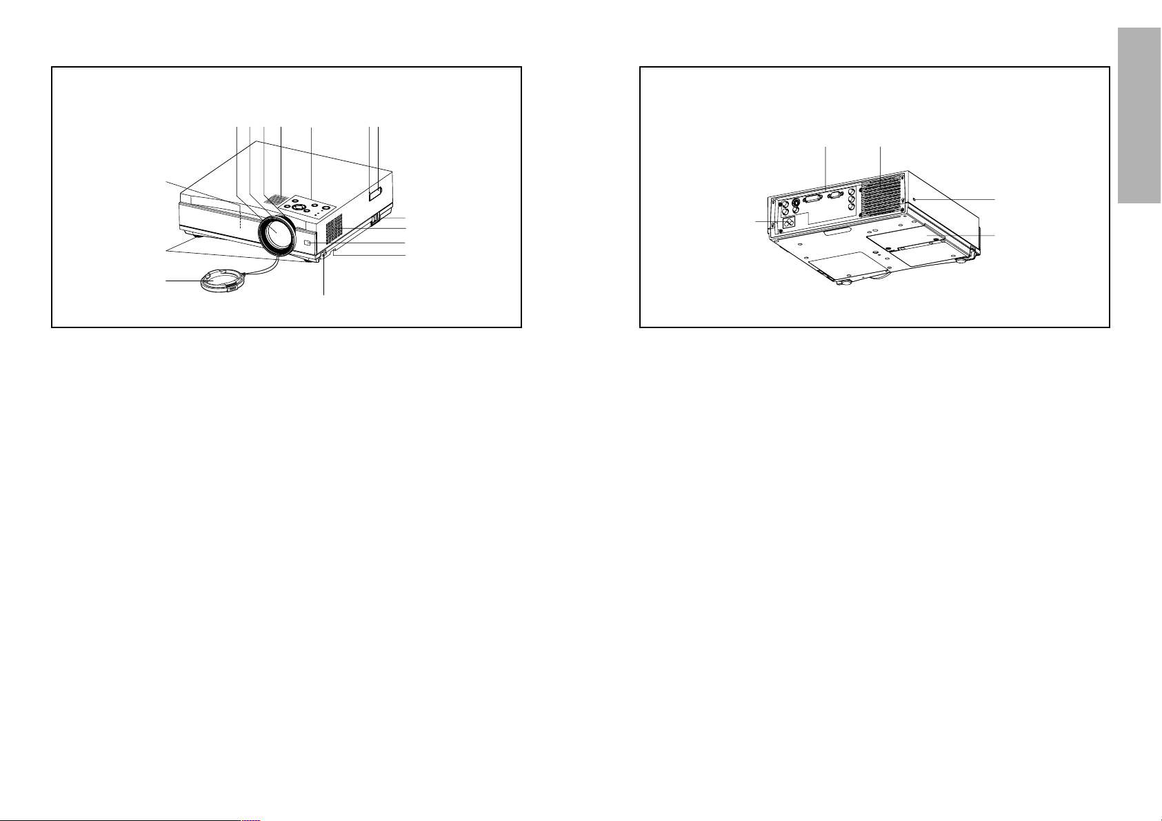
# Air outlet port
Do not cover this port.
WARNING
Do not bring your hands or other
objects close to the air outlet
port.
B Heated air comes out of the air
outlet port. Do not bring your
hands or face, or objects which
cannot withstand heat close to
this port, otherwise burns or
damage could result.
$ Connector panel
(page 16)
% Power input socket (AC IN)
(page 22)
The accessory power cord is
connected here.
Do not use any power cord other
than the accessory power cord.
& Lamp unit holder
(page 55)
NOTE:
B During projection of an image, the
cooling fan will operate, emitting
a small noise as it operates.
Turning the lamp on or off will
cause this noise to increase a
little.
B By using the OPTION menu to
set “LAMP POWER” to LOW, the
operating sound of the fan can be
reduced. (Refer to page 40.)
' Security lock
This can be used to connect a
commercially-available theftprevention cable (manufactured
by Kensington). This security lock
is compatible with the Microsaver
Security System from
Kensington. Contact details for
this company are given below.
Kensington Technology Group
ACCO Brands Inc.
2855 Campus Drive
San Mateo, CA 94403 USA
Tel (650)572-2700
Fax (650)572-9675
http://www.kensington.com/
http://www.gravis.com/
Projector <Back and bottom>
Location and function of each part
# Speaker
$ Zoom ring
(page 23)
% Focus ring
(page 23)
& Projection lens
' Air inlet ports
Do not cover this port.
( Front adjustable legs(L/R)
(page 22)
) Lens cover
* Leg adjuster buttons(L/R)
(page 22)
This button is used to unlock the
front adjustable legs. Press to
adjust the angle of tilt of the
projector.
+ Air filter
(page 53)
, Remote control signal receptor
(page 17)
- MAIN POWER switch
(pages 22 and 23)
. SD memory card slot
(page 42)
Insert the SD memory card into
here after opening the cover.
/ Access lamp
(page 42)
Flashes while the projector is
being accessed for reading or
writing the data in the SD
memory card.
0 Projector control panel
(page 14)
Projector <Top, right and front>
#$%&
'
(
)
*
-
+
,
'
./0
#$
%
&
'
Page 8
ENGLISH-15
Preparation
14-ENGLISH
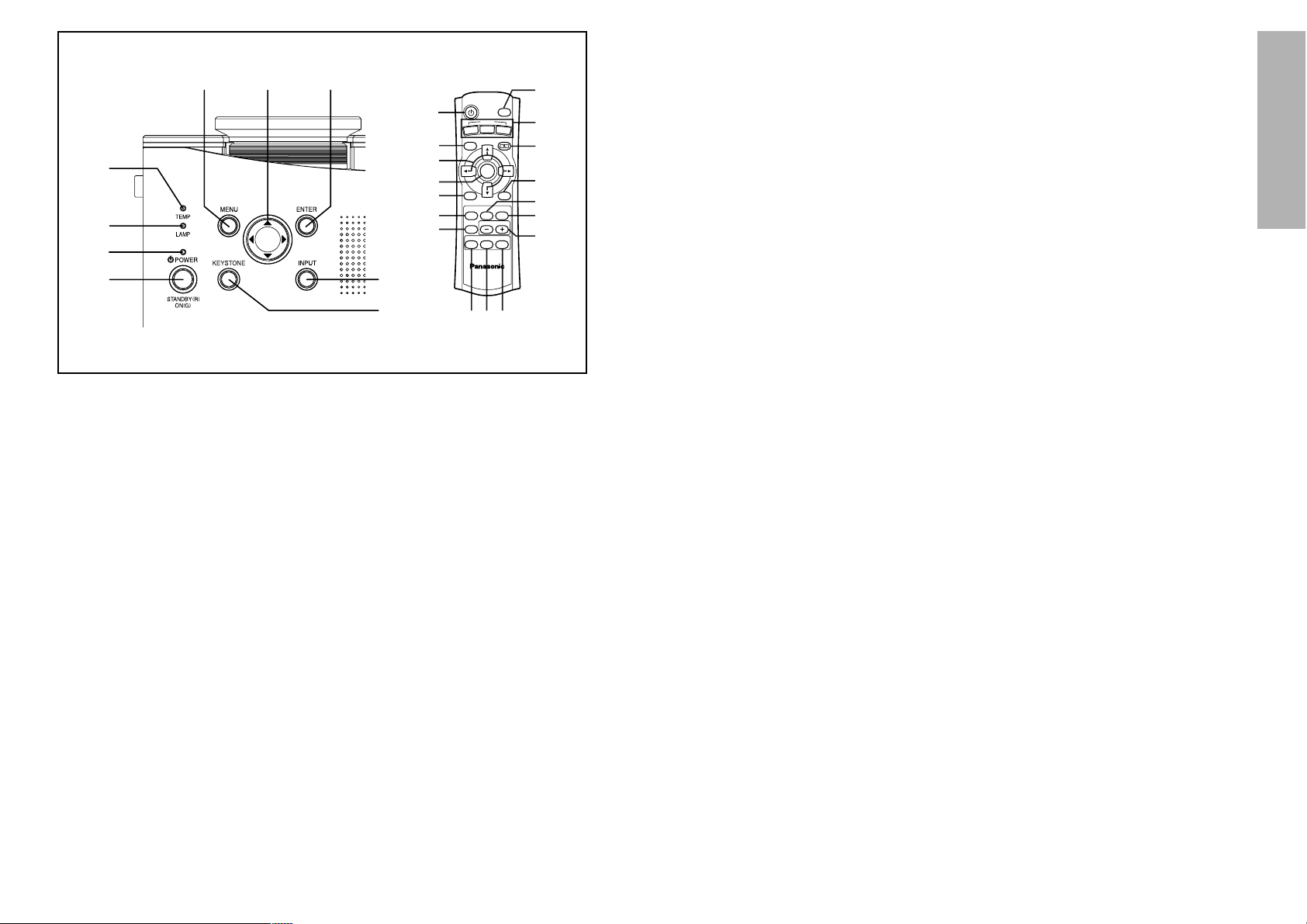
+ KEYSTONE buttons
(pages 28 and 29)
This button is used to correct
keystone distortion of the
projected image when the
projector position is tilted upward
or downward.
, NORMAL button
(page 27)
This button is used to reset the
projector adjustment values to the
factory default settings.
- ASPECT button
(page 30)
This button is used for aspect
adjustment (vertical and
horizontal proportions).
. MUTE button
(page 33)
This button momentarily stops
output of the projector’s built-in
speaker.
/ LIGHT button
This button is used to illuminate
the buttons on the remote control
unit.
0 FREEZE button
(page 36)
This button is used to
momentarily freeze projection so
that a still picture is displayed.
1 MODE PICTURE button
(page 32)
This button is to display the
PICTURE MODE menu.
2 MEMORY USER button
(page 36)
This button is to display the
MEMORY LOAD menu.
3 VOLUME +/- buttons
These buttons are used to adjust
the volume of the sound output
from the projector’s built-in
speaker.
4 SD button
(page 43)
This button is to select the SD
CARD screen.
5 SD MENU button
(page 43)
This button can be used to return
to a previous screen when SD
CARD screen is selected.
6 SD TIME button
(page 49)
This button is used to display or
clear the playing time when a
moving picture stored on the SD
card is played back.
# TEMP indicator
(page 51)
This indicator illuminates if an
abnormally high temperature is
detected inside the projector. If
the temperature rises above a
certain level, the power supply
will be turned off automatically
and the indicator will illuminate or
flash.
$ LAMP indicator
(page 52)
This indicator illuminates when it
is time to replace the lamp unit. It
flashes if a circuit abnormality is
detected.
% Power indicator
(pages 22 and 23)
This indicator illuminates red
when the main power is switched
on (Standby Mode), and it
illuminates green when projection
of an image begins.
& POWER button
(pages 22 and 23)
' MENU button
(page 24)
This button is used to display
menu screens. When a menu
screen is being displayed, it can
be used to return to a previous
screen or to clear the screen.
( Arrow (FF, GG, IIand HH)
buttons
(page 26)
These buttons are used to select
and adjust items in the on-screen
menu screens.
) ENTER button
(page 26)
This button is used to accept and
to activate items selected in the
on-screen menus.
* Input select button
(INPUT/VIDEO/COMPONENT/
PC button) (page 22)
<Projector control panel and remote control unit>
*
+
'
(
&
1
2
3
456
)
0
,
.
/
#
$
%
&
'()
*
+
P
C
POWER
LIGHT
INPUT
ENTER
MENU
FREEZE
NORMAL
ASPECT
USER
MEMORY
VOLUME
PICTURE
MODE
SD
MUTE
SD TIME
MENU
LCD PROJECTOR
V
I
D
E
O
C
M
P
N
T
COMPONENT
KEYSTONE
B The remote control unit and the projector itself have the same control
buttons available.
Page 9
ENGLISH-17
Preparation
16-ENGLISH
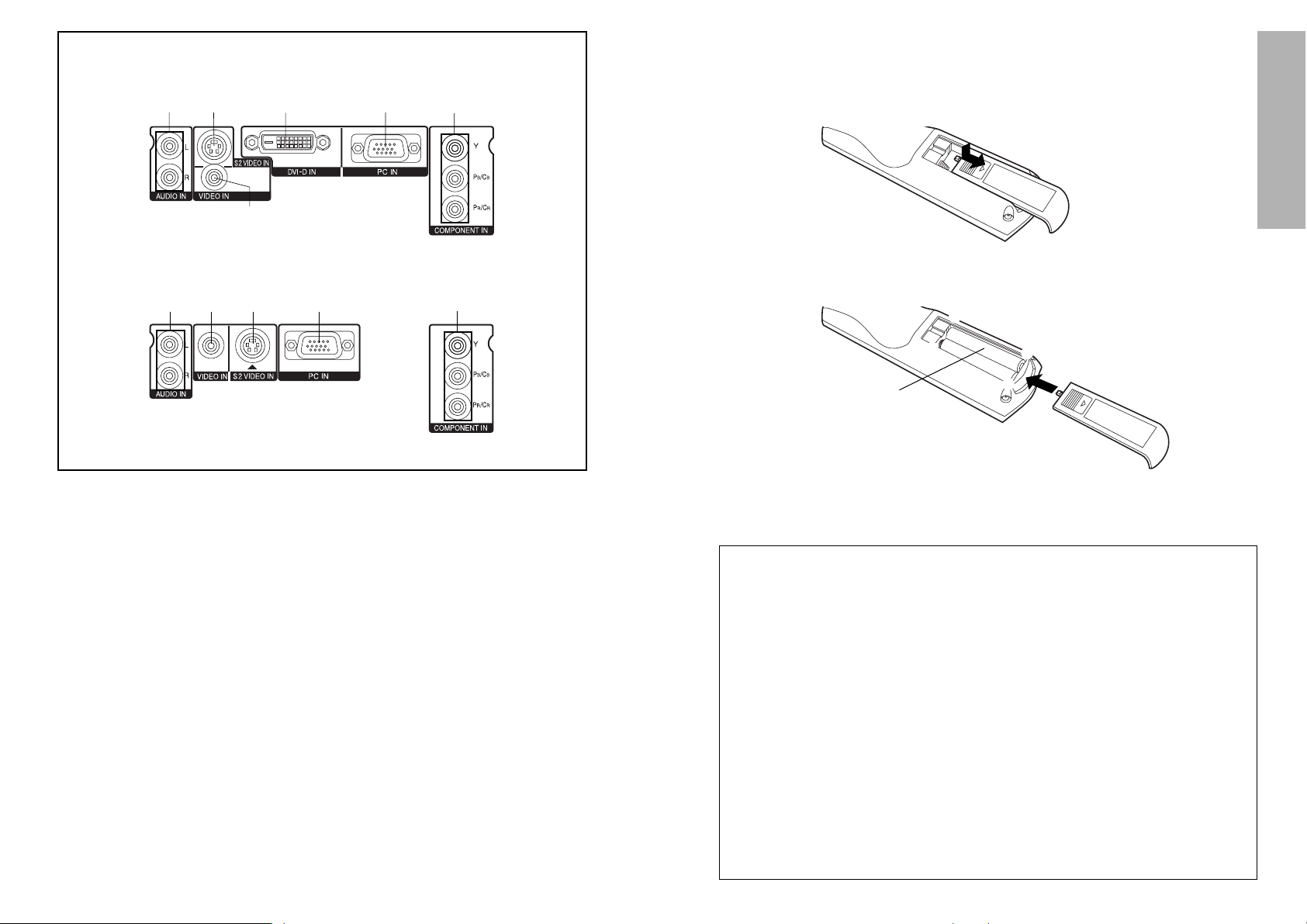
<Connector panel>
<PT-AE300U>
<PT-AE200U>
#$%& '(
$% '
#
(
# AUDIO L-R input jacks
(page 18)
$ VIDEO input jack
(page 18)
This jack is used to input video
signals from a video equipment
such as a video deck.
% S2 VIDEO input connector
(page 18 and 30)
This connector is used to input
signals from an S-VIDEOcompatible equipment such as a
video deck. The connector is
compatible with S2 and S1
signals, and projector aspect is
automatically adjusted according
to the type of signal received.
& DVI-D IN connector
(page 20)
This connector is used to input
DVI-D signals.
' RGB input connector
(page 20)
This connector is used to input
RGB signals from a PC.
( YP
BPR(CBCR) input jacks
(page 19)
These jacks are used to input
YPBPR signals from compatible
equipment such as DVD players.
NOTE:
B If there are any obstacles in between
the remote control unit and the
receivers, the remote control unit may
not operate correctly.
B
If strong light is allowed to shine onto
the remote control signal receiver,
correct remote control operation may
not be possible. Place the projector as
far away from light sources as possible.
B If facing the remote control unit
toward the screen to operate the
projector, the operating range of the
remote control unit will be limited by
the amount of light reflection loss
caused by the characteristics of the
screen used.
NOTE:
B Do not drop the remote control unit.
B Keep the remote control unit away from liquids.
B Remove the batteries if not using the remote control unit for long periods.
B Do not use rechargeable batteries.
Operating range
If the remote control unit is held so
that it is facing directly in front of the
remote control signal receptors on
the front of the projector, the
operating range is within
approximately 7 m (23´) from the
surfaces of the receptors.
Furthermore, the remote control unit
can be operated from an angle of
±30° to the left or right and ±15°
above or below the receptors.
# Open the cover.
AAA batteries
(two)
$ Insert the batteries so that the polarities are
correct, and then close the cover.
〇
+
〇−
〇−
〇
+
Using the remote control unit
Operating range
Page 10
18-ENGLISH ENGLISH-19
Preparation
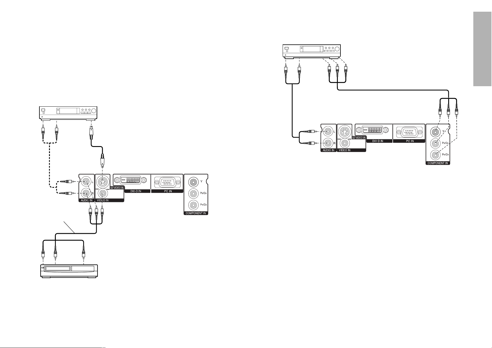
Example of connecting to video equipment
DVD player
Video deck
NOTE:
B Only one audio system circuit is available for the AUDIO IN L-R jacks, so if
you wish to change the audio input source, you will need to remove and
insert the appropriate plugs.
Connections
Notes on connections
B Read the instruction manual for each system component carefully before
connecting it.
B Turn off the power supply for all components before making any
connections.
B If the cables necessary for connecting a component to the system are not
included with the component or available as an option, you may need to
fashion a cable to suit the component concerned.
To video output
Video/Audio cable
(accessory)
To audio
output
To audio
output
To S-Video output
Example of connecting to equipment compatible
with YP
BPR(CBCR) signals
NOTE:
B Refer to page 61 for a list of compatible YPBPR signals which can be input
to the projector.
B Only one audio system circuit is available for the AUDIO IN L-R jacks, so if
you wish to change the audio input source, you will need to remove and
insert the appropriate plugs.
DVD player
To YP
BPR
output
To audio
output
* This illustration is an example of
connection for the PT-AE300U.
* This illustration is an example of
connection for the PT-AE300U.
Page 11
20-ENGLISH ENGLISH-21
Preparation
Setting-up
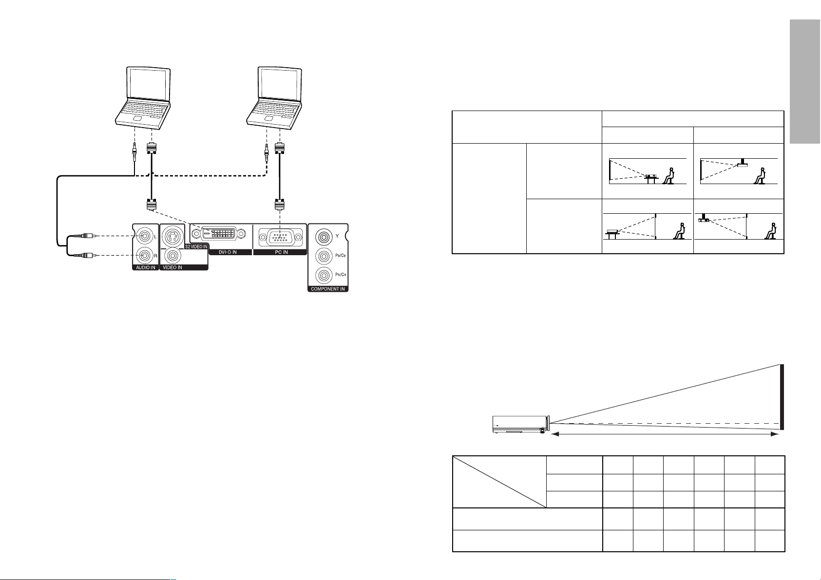
Projection methods
The projector can be set up so that any one of the following four projection
methods can be used. Select whichever projection method matches the
setting-up method. (The projection method can be set from the OPTION
menu. Refer to page 40 for details.)
FRONT/REAR
FRONT
REAR
(Factory default setting)
NOTE:
B You will need to purchase the separate ceiling bracket (ET-PKE300) when
using the ceiling installation method.
Projector position
The projection range of this projector is 1.2 m – 7.4 m.
The lower edge of the projected image falls about 0.1 m from the center of
the lens.
For details about projected image distances, refer to page 65.
DESK/CEILING
DESK CEILING
NOTE:
B It is better to shut down the computer before turning off the MAIN POWER
switch of the projector.
B Refer to the list of compatible signals on page 61 for the types of RGB
signals which can be input to the projector by connecting a computer.
B Only one audio system circuit is available for the AUDIO IN L-R jacks, so if
you wish to change the audio input source, you will need to remove and
insert the appropriate plugs.
B The PT-AE200U does not have a DVI-D input (DVI-D IN) connector.
Example of connecting to computer
Computer Computer
To RGB
output
To audio
output
To audio
output
To DVI-D
output
* This illustration is an example of
connection for the PT-AE300U.
Projection Distance
Projection
Distance
0.9 m
(2´11˝)
1.2 m
(3´11˝)
1.4 m
(4´7˝)
1.9 m
(6´2˝)
2.2 m
(7´2˝)
2.5 m
(8´2˝)
2.9 m
(9´6˝)
3.1 m
(10´2˝)
3.7 m
(12´1˝)
4.7 m
(15´5˝)
5.6 m
(18´4˝)
6.2 m
(20´4˝)
7.4 m
(24´3˝)
Minimum Distance
Maximum Distance
Screen Size
(16:9)
0.5 m
(1´7˝)
1.3 m
(4´3˝)
0.8 m
(2´7˝)
1.8 m
(5´10˝)
1.0 m
(3´3˝)
2.2 m
(7´2˝)
1.3 m
(4´3˝)
3.3 m
(10´9˝)
1.9 m
(6´2˝)
4.4 m
(14´5˝)
2.5 m
(8´2˝)
40˝ 60˝ 80˝ 100˝ 150˝
200˝
Diagonal length
Height
Width
Page 12
22-ENGLISH ENGLISH-23
P
C
POWER
LIGHT
INPUT
ENTER
MENU
FREEZE
NORMAL
ASPECT
USER
MEMORY
VOLUME
PICTURE
MODE
SD
MUTE
SD TIME
MENU
V
I
D
E
O
C
M
P
N
T
COMPONENT
KEYSTONE
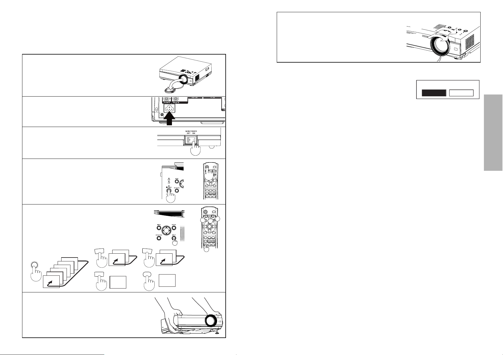
Basic Operation
Turning off the power
# Press the POWER button. “POWER OFF” is
displayed on the screen.
$ Select “OK” using the I and H buttons and
press the ENTER button.
The lamp unit will switch off and the picture will stop being projected. (The
power indicator on the projector will illuminate orange.)
% Wait until the power indicator on the projector illuminates red (until
the cooling fan stops).
Do not in any way cut power to the projector while the cooling fan is still
operating. Be careful not to switch off the MAIN POWER switch of the
projector, unplug the power cord from the electrical outlet or turn off in-line
switches such as tabletop power switches.
& Press the MAIN POWER switch to the “O” side to turn off the power.
NOTE:
B After the power is turned off, the lamp unit will take some time to cool
down. If you turn the power back on again before the lamp unit has cooled
down, the lamp unit may not turn on straight away, but it will turn on
automatically after a short period. (During this time, the power indicator on
the projector will flash orange.)
B When the projector is in standby mode (the power indicator on the
projector is illuminated red), the projector will still draw a maximum 1.5 W
of power, even when the cooling fan has stopped.
B If the MAIN POWER switch is accidentally turned off while the projector is
being used, the lamp unit may not turn on straight away after the power is
turned back on. In such cases, the lamp unit will turn back on
automatically after a short period. (During this time, the power indicator on
the projector will flash green.)
B A tinkling sound may be heard while the power indicator is turned off, but
this is not a sign of a malfunction.
B You can also turn off the power by pressing the POWER button twice or
by holding down it for at least 0.5 seconds.
Starting to use
Turning on the power
Please ensure that all preparations have been completed before turning on
the power. (Refer to pages 18 – 21.)
# Remove the lens cover.
$ Connect the accessory power cord.
% Press the MAIN POWER switch to
the “|” side to turn on the power.
The power indicator on the projector
will illuminate red.
& Press the POWER button.
The power indicator on the projector
will flash green. After a short period,
the button will illuminate green, and a
picture will be projected.
Zoom
Focus
) Turn the focus/zoom ring to adjust
the projected image focus and size.
POWER OFF
OK CANCEL
( While pressing the adjuster buttons,
adjust the forward/back angle of tilt
of the projector.
If there is keystone distortion in the
projected images, carry out keystone
correction as described on page 28.
' Press the INPUT select button to
select the input signal.
The input signal selected will change
as shown at below-right each time an
input select button (INPUT/VIDEO/
CMPNT/PC/SD) is pressed.
*“DVI” is only
for PT-AE300U.
INPUT
S-VIDEO
VIDEO
SD CARD
DVI
PC
Y・PB・PR
S-VIDEO
VIDEO
Y・PB・PR
SD CARD
DVI
PC
V
I
D
E
O
C
M
P
N
T
P
C
SD
POWER
O
E
D
I
V
MENU
NORMAL
ASPECT
MUTE
SD TIME
COMPONENT
LIGHT
INPUT
P
N
M
T
C
P
C
KEYSTONE
ENTER
FREEZE
MEMORY
MODE
USER
PICTURE
VOLUME
SD
MENU
Page 13
24-ENGLISH ENGLISH-25
Basic Operation
When a YPBPR signal is being
input or SD CARD is selected
When a PC/DVI signal is being input
* “GAMMA ADJUST” is not displayed by PT-AE200U.
* “W-BAL R”, “W-BAL G” and “W-BAL B” are not displayed when DVI signal
is being input.
PICTURE
PICTURE MODE NORMAL
CONTRAST 0
BRIGHT 0
COLOR 0
TINT 0
SHARPNESS 0
COLOR TEMP. 0
GAMMA ADJUST
MEMORY SAVE
MEMORY LOAD
TV-SYSTEM AUTO1
SELECT ADJ ESC
PICTURE
PICTURE MODE NORMAL
CONTRAST 0
BRIGHT 0
COLOR 0
TINT 0
SHARPNESS 0
COLOR TEMP. 0
GAMMA ADJUST
MEMORY SAVE
MEMORY LOAD
SIGNAL MODE 525I
SELECT ADJ ESC
PICTURE
PICTURE MODE NORMAL
CONTRAST 0
BRIGHT 0
SHARPNESS 0
COLOR TEMP. 0
W-BAL R 0
W-BAL G 0
W-BAL B 0
GAMMA ADJUST
MEMORY SAVE
MEMORY LOAD
SIGNAL MODE XGA
SELECT ADJ ESC
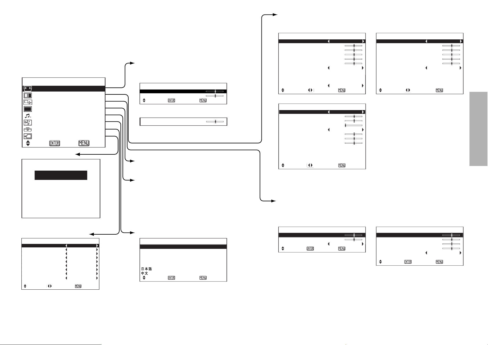
PICTURE menu (page 34)
When an S-VIDEO/VIDEO signal
is being input
When a PC signal is being input
POSITION
H-POSITION 0
V-POSITION 0
ASPECT 16:9
SELECT
ENTER ESC
POSITION
H-POSITION 0
V-POSITION 0
DOT CLOCK 0
CLOCK PHASE 0
ASPECT 4:3
AUTO SETUP
SELECT
ENTER ESC
POSITION menu (page 38)
When an S-VIDEO/VIDEO/YPBPR/
DVI signal is being input or SD
CARD is selected
* “ASPECT” can be adjusted only
when a DVI signal is being input
or when “SD CARD” is selected.
On-screen menus
Menu screens
The various settings and adjustments for this projector can be carried out by
selecting the operations from on-screen menus.
The general arrangement of these menus is shown below.
MAIN MENU
OPTION menu (page 39)
SD menu (page 43)
LANGUAGE menu (page 33)
SHUTTER function
(page 33)
Volume adjustment
Press the ENTER button, and
then press the I and H
buttons to adjust the volume.
NOTE:
B Keystone distortion of the on-screen display will not be corrected.
(PT-AE200U only)
MENU
KEYSTONE
PICTURE
POSITION
SHUTTER
VOLUME
LANGUAGE
OPTION
SD MENU
SELECT ENTER EXIT
OPTION
OSD ON
NR ON
PC PRIORITY NORMAL
BACK COLOR BLACK
4:3 H-POS CENTER
FRONT/REAR FRONT
DESK/CEILING DESK
FAN CONTROL NORMAL
LAMP POWER HIGH
LAMP RUNTIME 5H
SELECT ADJ ESC
LANGUAGE ENGLISH
ENGLISH
DEUTSCH
FRANÇAIS
ESPAÑOL
ITALIANO
SELECT
ENTER ESC
Keystone correction
(page 28)
For PT-AE300U
For PT-AE200U
* Only vertical keystone distortion
is corrected by PT-AE200U.
PICTURE
SLIDE SHOW
VIDEO
KEYSTONE
H-KEYSTONE 0
V-KEYSTONE 0
SELECT
ENTER ESC
KEYSTONE 0
Page 14
26-ENGLISH ENGLISH-27
Basic Operation
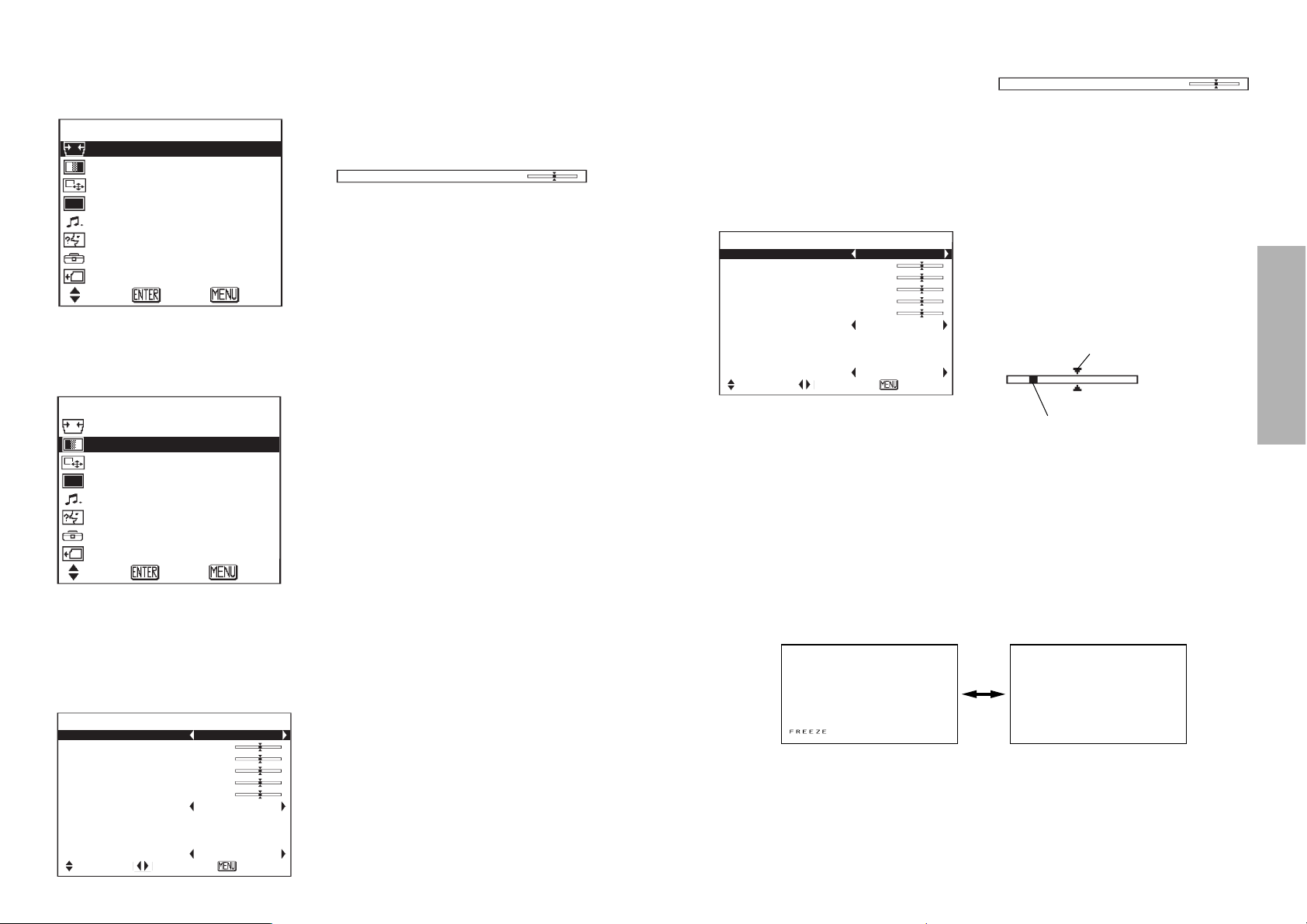
Returning a setting to
the factory default
If you press the NORMAL button on
the remote control unit, you can
return settings to the factory default
settings. However, the operation of
this function varies depending on
which screen is being displayed.
B When a menu screen is being
displayed
All items displayed will be returned
to their factory default settings, and
the bar scale will appear white.
B When an individual adjustment
screen is being displayed
Only the item displayed will be
returned to the factory default
setting, and the bar scale will
appear white.
NOTE:
B Triangle symbols above and
below a menu bar indicate the
factory default setting. Items
which do not have these triangle
symbols cannot be returned to
the factory default setting.
Indicates the standard factory
default setting
Indicates the current adjustment
value
B The positions of triangle symbols
vary depending on the type of
signal being input.
Using the freeze function
The picture will alternate between a still picture and a moving picture each
time the FREEZE button on the remote control unit is pressed.
Still picture Moving picture
Menu operation guide
# Press the MENU button.
The MAIN MENU screen will be
displayed.
$ Press the F or G arrow
buttons to select an item.
Selected items will be displayed
in blue.
% Press the ENTER button to
accept the selection.
The selected menu screen or
adjustment screen will then be
displayed.
(Example: PICTURE menu)
MENU
KEYSTONE
PICTURE
POSITION
SHUTTER
VOLUME
LANGUAGE
OPTION
SD MENU
SELECT ENTER EXIT
MENU
KEYSTONE
PICTURE
POSITION
SHUTTER
VOLUME
LANGUAGE
OPTION
SD MENU
SELECT ENTER EXIT
PICTURE
PICTURE MODE NORMAL
CONTRAST 0
BRIGHT 0
COLOR 0
TINT 0
SHARPNESS 0
COLOR TEMP. 0
GAMMA ADJUST
MEMORY SAVE
MEMORY LOAD
TV-SYSTEM AUTO1
SELECT ADJ ESC
& Press the F or G buttons to
select an item, and then press
the I or H buttons to change
or adjust the setting.
An individual adjustment screen
such as the one shown below will
be displayed for bar-scale items.
The bar scale will turn green
when any adjustment changes
the setting from the factory set
value.
For items without any selective
arrow or bar-scale, press the
ENTER button. The menu screen
for the item will then be
displayed.
Unavailable on-screen
menu items
This projector has unadjustable
items and unusable functions
depending on the signal being input.
When an item cannot be adjusted or
a function cannot be used, the
corresponding on-screen menu
display does not appear, and the
item or function will not work even if
the ENTER button is pressed.
Returning to the
previous screen
If you press the MENU button while
a menu screen is being displayed,
the display will return to the
previous screen.
If you press the MENU button while
the MAIN MENU screen is being
displayed, the MAIN MENU screen
will be cleared.
BRIGHT 0
PICTURE
PICTURE MODE NORMAL
CONTRAST 0
BRIGHT 0
COLOR 0
TINT 0
SHARPNESS 0
COLOR TEMP. 0
GAMMA ADJUST
MEMORY SAVE
MEMORY LOAD
TV-SYSTEM AUTO1
SELECT ADJ ESC
BRIGHT 0
Page 15
28-ENGLISH ENGLISH-29
Basic Operation
NOTE:
B You can also correct keystone distortion by selecting the KEYSTONE item
in the MAIN MENU and pressing ENTER.
B Vertical and horizontal keystone distortion can be corrected to ±30° of the
angle of tilt by PT-AE300U. Vertical keystone distortion can be corrected
to ±30° of the angle of tilt by PT-AE200U. However, the greater the
correction amount, the more the picture quality will deteriorate, and the
harder it will become to achieve a good level of focus. To obtain the best
picture quality, set up the projector and screen in such a way that the
amount of keystone correction required is as minimal as possible.
B The picture size will also change when correction of keystone distortion is
carried out.
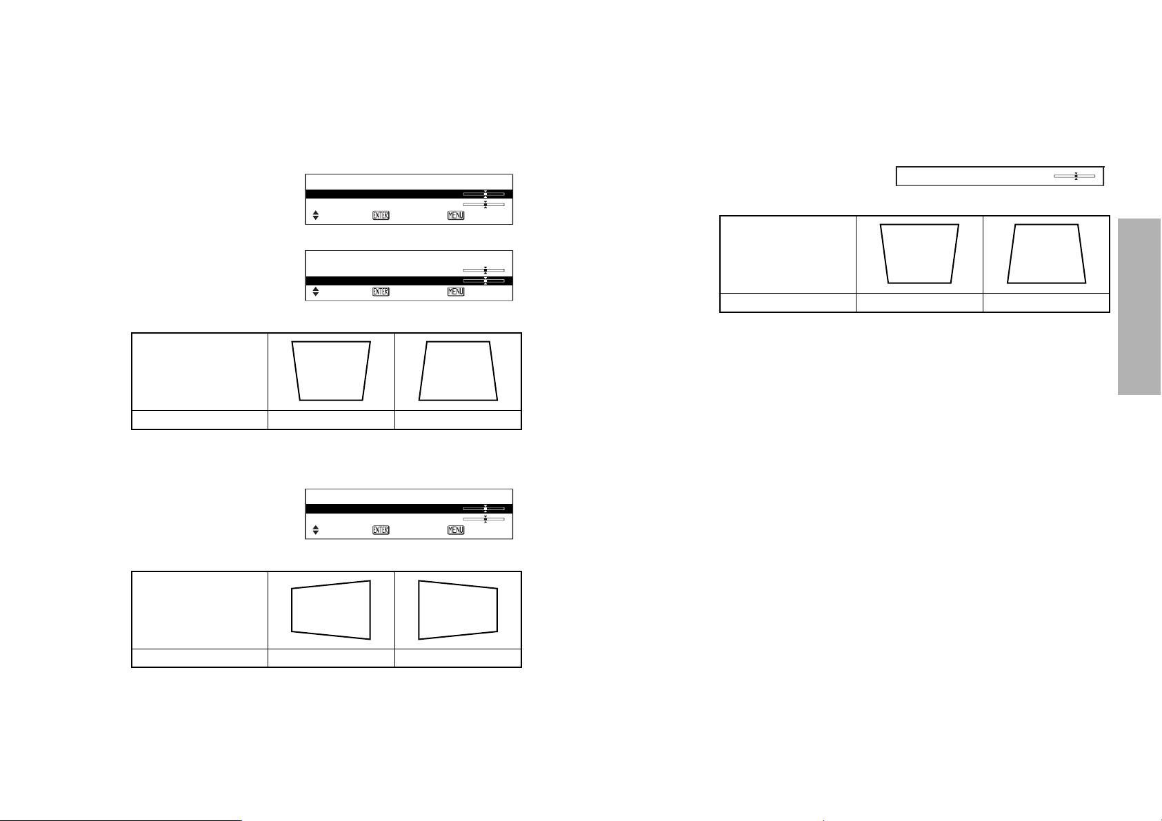
Correcting keystone distortion
When either the projector or the screen is tilted, the keystone distortion will
affect the image. You can correct the image proportions by the following
procedure.
Picture condition
Operation
Press the Hbutton. Press the Ibutton.
Picture condition
Operation
Press the Hbutton. Press the Ibutton.
For PT-AE300U
Horizontal and vertical keystone distortion can be corrected by following
procedures.
# Press the KEYSTONE button to display
the KEYSTONE menu.
$ To correct vertical keystone distortion
Select “V-KEYSTONE” by pressing
the F or G buttons and then press
the ENTER button.
% To correct the horizontal keystone distortion
Select “H-KEYSTONE” by pressing
the F or G buttons and then press
the ENTER button.
& Press the MENU button.
The display will then return to the previous screen.
For PT-AE200U
Vertical keystone distortion can be corrected by following procedures.
# Use the KEYSTONE button to
obtain image balance.
KEYSTONE 0
$ Press the MENU button to return to the previous screen.
Picture condition
Operation
Press the Hbutton. Press the Ibutton.
H-KEYSTONE 0
V-KEYSTONE 0
SELECT
KEYSTONE
H-KEYSTONE 0
V-KEYSTONE 0
SELECT
H-KEYSTONE 0
V-KEYSTONE 0
SELECT
KEYSTONE
ENTER ESC
ENTER ESC
KEYSTONE
ENTER ESC
Page 16
30-ENGLISH ENGLISH-31
Basic Operation
Setting the ASPECT
This projector allows you to change the aspect ratio to match the type of
input signal. Pressing the ASPECT button will change the aspect ratio
according to the successive settings shown below.
(You can also change the aspect ratio by selecting the POSITION item in the
MAIN MENU and pressing ENTER.)
* “S4:3” or “S16:9” can be selected when NTSC, M-NTSC, PAL-M, PAL60,
525p and 525i signals are being input to the PT-AE300U.
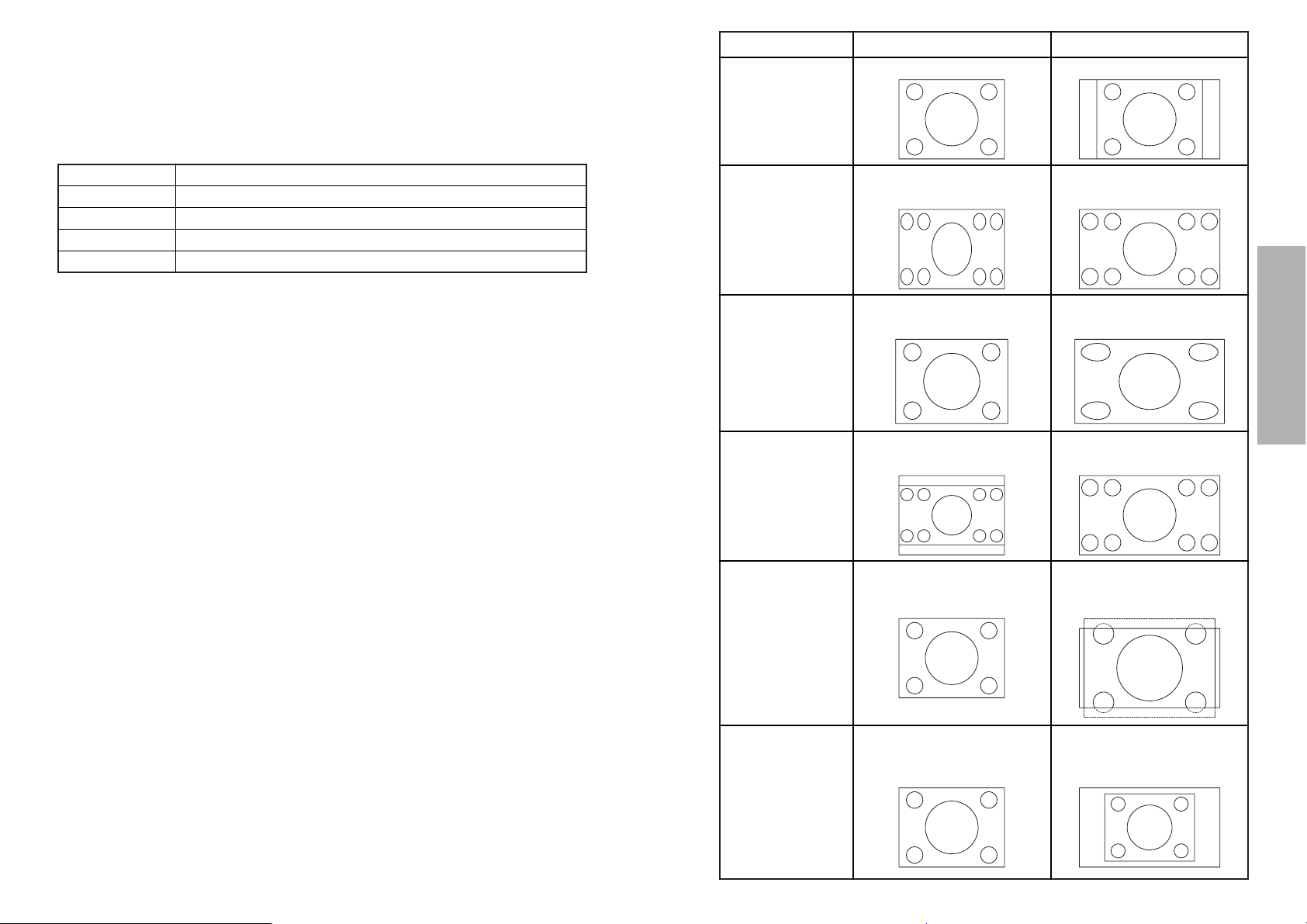
Illustrations for aspect ratio settings are shown on the next page. Refer to
this illustration for assistance in selecting a suitable aspect ratio.
About S1/S2 video signals:
B S1/S2 video signals are for 16:9 images and include a notification signal
when being played by devices such as a DVD player.
B When the projector is set to the “S1/S2” setting shown above, it will detect
those notification signals and automatically switch to the correct aspect
ratio for projection.
NOTE:
B This projector is equipped with an aspect ratio selection function. However, if a
mode which does not match the aspect ratio of the input signal is selected, it
may affect the quality of viewing of the original picture. Keep this in mind when
selecting the aspect ratio.
B If using this projector in places such as cafes or hotels with the aim of
displaying programmes for viewing for a commercial purpose or for public
presentation, note that if the aspect ratio (16:9) selection function is used to
change the aspect ratio of the screen picture, you may be infringing the rights
of the original copyright owner for that program under copyright protection laws.
B If a normal (4:3) picture which was not originally intended for wide-screen
viewing is projected onto a wide screen, distortion may occur around the edges
of the picture so that part of the picture is no longer visible. Such programmes
should be viewed in 4:3 mode to give proper consideration to the aims and
intentions of the original program’s creator.
B The following signals have resolutions that are 16:9 image sizes. The aspect
ratios for these signals cannot be changed while being played because they
are already established. (Refer to page 61.)
HDTV60, HDTV50, 750p, WIDE 400/480/600/720/768
B Image sizes such as Cinema-Vision that project wider than the 16:9 ratio will
have narrow black fields at the top and bottom.
S-VIDEO S1/S2\4:3\16:9\JUST\ZOOM\*S4:3\*S16:9
VIDEO/YP
BPR 4:3\16:9\JUST\ZOOM\*S4:3\*S16:9
PC 4:3\16:9\V SCROLL
DVI 4:3\16:9
4:3 4:3 Input signal 4:3
16:9 Squeezed signal (image
contracted horizontally)
Horizontal expansion of
projected image
JUST 4:3 Input signal
Horizontal expansion of projected image
(Center of image is less distorted)
ZOOM Letter box signal Expansion preserves
original ratio
V SCROLL 4:3 Input signal
Enlarges image approximately 1.2
times (Vertical position can be
adjusted by the G and F buttons)
ASPECT Input signal Projected Image
S4:3
S16:9
(PT-AE300U only)
4:3 Input signal
Image which is projected at an
aspect ratio of 4:3 or 16:9 without
being expanded vertically.
SD CARD 4:3\16:9\JUST\ZOOM
Page 17
32-ENGLISH ENGLISH-33
Basic Operation
Changing the display language
Indicates the language which is
currently set
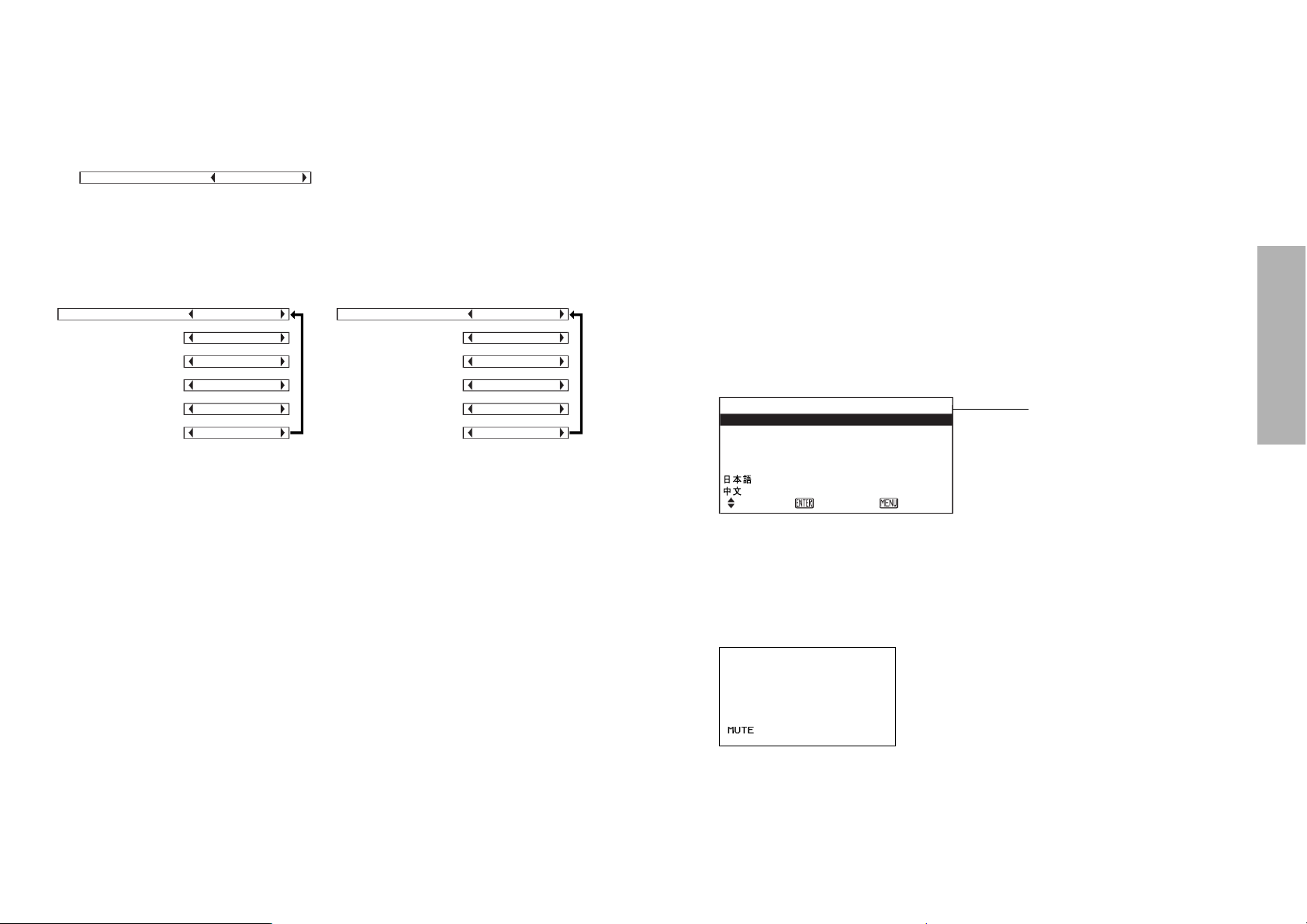
# Select LANGUAGE from the MAIN MENU screen and then press the
ENTER button.
$ Use the FG buttons to select a language and then press the ENTER
button.
LANGUAGE ENGLISH
ENGLISH
DEUTSCH
FRANÇAIS
ESPAÑOL
ITALIANO
SELECT
ENTER ESC
Using the shutter function
The shutter function can be used to momentarily turn off the picture and
sound from the projector when the projector is not being used for short
periods of time, such as during breaks in meetings or when carrying out
preparation. The projector uses less power in shutter mode than it does in
normal projection mode.
# Select SHUTTER from the MAIN MENU screen and then press the
ENTER button.
$ Press any button on either the projector or remote control unit to
return to normal operating mode.
Muting the sound
The sound can be muted for temporary interruptions such as telephone calls.
Press the MUTE button once to turn off sound, and press MUTE again to
regain sound.
NOTE:
B If the power is turned off or the VOLUME +/- buttons are pressed, the
mute will be canceled.
Selecting the picture mode
You can select the appropriate picture mode for the type of projected image
by the following procedure.
(The picture mode can be also selected in the PICTURE menu.)
# Press the MODE PICTURE button to display the PICTURE menu.
$ Select an item by pressing the I or H buttons.
When S-VIDEO/VIDEO/YP
BPR is
being input or when SD CARD is
selected
When PC/DVI is being input
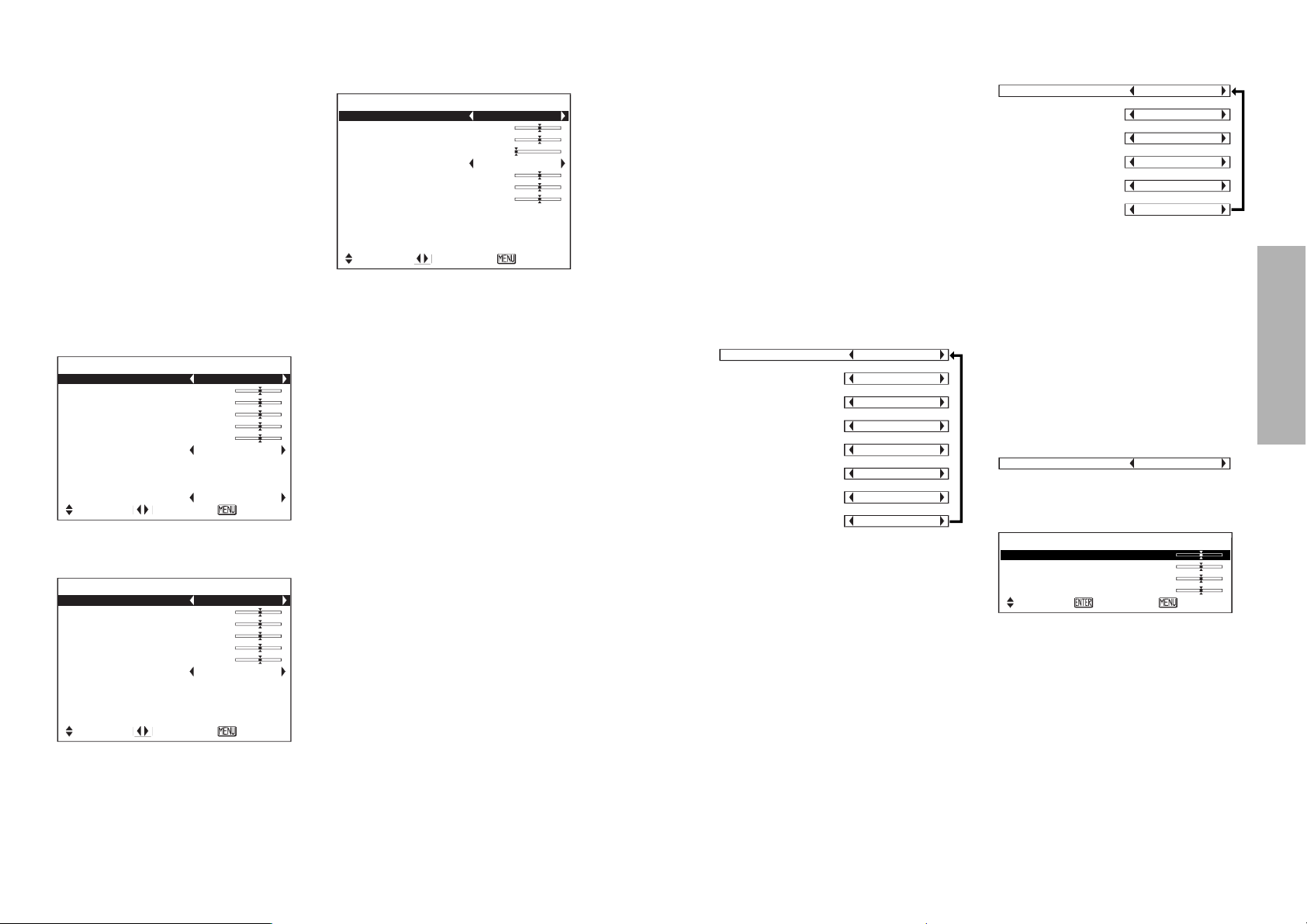
NORMAL ............When the brightness of the room is at a standard level.
DYNAMIC ...........When the room is brighter.
CINEMA1............When watching movies.
CINEMA2............When watching movies with lighter and clearer pictures.
MUSIC ................When watching music programs such as concerts or live
performances.
Quality of image will be with high impact and vividness.
SPORTS .............When watching sports programs such as baseball or
soccer games.
Dark parts and players will be projected distinctly, making it
easy to see quick motions.
NATURAL...........To project the image faithfully from the image source.
PICTURE MODE NORMAL
PICTURE MODE NORMAL
[
DYNAMIC
[
CINEMA
1
[
CINEMA
2
[
MUSIC
[
SPORTS
PICTURE MODE NORMAL
[
DYNAMIC
[
CINEMA
1
[
CINEMA
2
[
MUSIC
[
NATURAL
Page 18
34-ENGLISH ENGLISH-35
Basic Operation
TINT
(NTSC/NTSC 4.43/YPBPR /SD
CARD only)
This adjusts the flesh tones in the
picture. Press the H button to make
flesh tones more greenish, and
press the I button to make the
flesh tones more reddish.
SHARPNESS
Press the H button to make the
picture details sharper, and press
the I button to make the picture
details softer.
TV SYSTEM
(S-VIDEO/VIDEO only)
AUTO1 The projector
automatically distinguishes
between NTSC/NTSC
4.43/PAL/PAL60/SECAM
signals.
AUTO2 The projector
automatically distinguishes
between NTSC/PAL-
M/PAL-N signals.
This should normally be set to
“AUTO1” or “AUTO2”. If the signal is
of such poor quality that the correct
format cannot be automatically
distinguished, change the setting
manually to the required TV system.
Color Hue Setting (color
temperature)
* “USER” will not be displayed by
PT-AE200U.
This is used to adjust the white
areas of the picture if they appear
bluish or reddish.
USER (PT-AE300U only)
This item lets you make fine
adjustments to the color
temperature.
# Press the I or H buttons to
select the “USER” and press the
ENTER button.
$ Press the F or G buttons to select
an item and adjust the setting by
pressing the I or H buttons.
If the white area of the picture
appears bluish, adjust CONTRAST
B or BRIGHT B to a lower setting or
adjust the CONTRAST R or
BRIGHT R to a higher setting.
If it appears reddish, adjust
CONTRAST R or BRIGHT R to a
lower setting or adjust the
CONTRAST B or BRIGHT B to a
higher setting.
Adjust settings using CONTRAST R
or CONTRAST B under normal
conditions.
Adjusting the picture
Use the F and G buttons to select an
item, and then use the I and H buttons
to change the setting for that item.
For items with bar scales, press the
ENTER button or the I or H
buttons to display the adjustment
screen, and then use the I or H
buttons to make the adjustment.
For items without any selective
arrow or bar-scale, press the ENTER
button. The menu screen for the item
will then be displayed.
When an S-VIDEO/VIDEO signal is
being input
PICTURE
PICTURE MODE NORMAL
CONTRAST 0
BRIGHT 0
COLOR 0
TINT 0
SHARPNESS 0
COLOR TEMP. 0
GAMMA ADJUST
MEMORY SAVE
MEMORY LOAD
TV-SYSTEM AUTO1
SELECT ADJ ESC
When a YPBPR signal is being input
or SD CARD is selected
PICTURE
PICTURE MODE NORMAL
CONTRAST 0
BRIGHT 0
COLOR 0
TINT 0
SHARPNESS 0
COLOR TEMP. 0
GAMMA ADJUST
MEMORY SAVE
MEMORY LOAD
SIGNAL MODE 525I
SELECT ADJ ESC
B “W-BAL R”, “W-BAL G” and “W-
BAL B” are not displayed when
DVI signal is being input.
PICTURE MODE
Refer to page 32 for details.
CONTRAST
This adjusts the contrast of the
picture. Press the H button to make
the picture brighter, and press the
I button to make the picture
darker. (Adjust the BRIGHT setting
first if required before adjusting the
CONTRAST setting.)
BRIGHT
This adjusts the darker areas (black
areas) in the picture. Press the H
button if dark areas are too solid (for
example, if hair is difficult to see),
and press the I button if black
areas are too light (grey rather than
black).
COLOR
(S-VIDEO/VIDEO/YPBPR /SD
CARD only)
Press the H button to make the
color more vivid in tone, and press
the I button to make the color
more pastel in tone.
When a PC/DVI signal is being input
PICTURE
PICTURE MODE NORMAL
CONTRAST 0
BRIGHT 0
SHARPNESS 0
COLOR TEMP. 0
W-BAL R 0
W-BAL G 0
W-BAL B 0
GAMMA ADJUST
MEMORY SAVE
MEMORY LOAD
SIGNAL MODE XGA
SELECT ADJ ESC
TV-SYSTEM AUTO1
[
AUTO2
[
NTSC
[
NTSC4.43
[
PAL
[
PAL-M
[
PAL-N
[
SECAM
COLOR TEMP. -2
[
COLOR TEMP. -1
[
COLOR TEMP. 0
[
COLOR TEMP. +1
[
COLOR TEMP. +2
[
COLOR TEMP. USER
COLOR TEMP. USER
CONTRAST R 0
CONTRAST B 0
BRITHT R 0
BRITHT B 0
COLOR TEMP.
SELECT
ENTER ESC
Page 19
36-ENGLISH ENGLISH-37
Basic Operation
Projecting sRGBcompatible pictures
sRGB is an international color
reproduction standard (IEC61966-2-
1) established by the International
Electrotechnical Commission (IEC).
If you would like the colours in
sRGB-compatible pictures to be
reproduced more faithfully, make
the following settings.
# Press the F or G button to
select “PICTURE MODE”, and
then use the I or H button to
select “NATURAL”.
$ Press the NORMAL button on
the remote control unit.
% Select the LAMP POWER item
in the OPTION menu by
pressing the F or G buttons
and set to “HIGH” by pressing
the I or H buttons.
NOTE:
B sRGB is only enabled when RGB
signals are being input .
When adjusting the black or neutral
color area of the picture, adjust it
using BRIGHT R or BRIGHT B.
WHITE BALANCE R/G/B
(PC only)
This is used to adjust the white
areas of the picture if they appear
colourised.
Press the I button to make the
selected color lighter.
Press the H button to make the
selected color stronger.
SIGNAL MODE
(PC/DVI/YPBPR only)
This displays the type of signal
which is currently being projected.
Refer to the table on page 61 for
details on each type of signal.
GAMMA ADJUST
(PT-AE300U only)
Press the ENTER button to display
the GAMMA ADJUST menu.
WHITE LEVELS
This is used for correcting the
gradation of a bright projected
image. To correct a white jump in
the picture, press the I buttons. To
raise the contrast ratio, press the H
buttons.
BLACK LEVELS
This is used for correcting gradation
of a dark projected image.
To correct black crushing, press the
H buttons. To raise the contrast
ratio, press the I buttons.
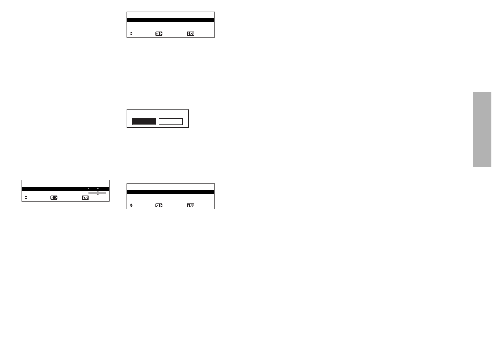
MEMORY SAVE
Press the ENTER button to display
the MEMORY SAVE menu.
Up to 3 settings can be saved in the
PICTURE menu.
Select the number in which you
wish to save the setting by pressing
the F or G buttons and then press
the ENTER button.
The confirmation screen will then be
displayed. Select “OK” by pressing
the I or H buttons and press the
ENTER button.
MEMORY LOAD
Press the ENTER button to display
the MEMORY LOAD menu.
(If any setting is not saved in the
MEMORY SAVE menu, the
MEMORY LOAD menu will not be
displayed.)
A setting saved in the MEMORY
SAVE menu can be retrieved using
MEMORY LOAD. Select the
number which you wish to retrieve
by pressing the F or G buttons and
then press the ENTER button.
NOTE:
B The MEMORY LOAD menu can
also be displayed by pressing the
MEMORY USER button.
B The number with which some
settings are saved using
MEMORY SAVE will only be
displayed in the MEMORY LOAD
menu.
GAMMA ADJUST
WHITE LEVELS 0
BLACK LEVELS 0
SELECT
ENTER ESC
MEMORY 1
MEMORY 2
MEMORY 3
MEMORY SAVE
SELECT
ENTER ESC
MEMORY SAVE
OK CANCEL
MEMORY 1
MEMORY 2
MEMORY 3
MEMORY LOAD
SELECT
ENTER ESC
Page 20
38-ENGLISH ENGLISH-39
Basic OperationAdvanced Operation
Option settings
Use the F and G buttons to select
an item, then press the I or H
buttons to change the setting.
OSD
ON The signal name is
displayed in the top-right
corner of the screen when
the input signal is
changed.
OFF Use this setting when you
do not want the signal
name to be displayed.
NR (Noise Reduction)
(S-VIDEO/VIDEO/YPBPR only)
If noise occurs from the projector
because of a poor input signal, set
NR to “ON”.
To turn off the NR (Noise
Reduction) feature, set it to “OFF”.
PC PRIORITY
(PC only)
NORMAL displays the PC screen
data in a 4:3 aspect ratio.
WIDE displays the PC screen data
in a 16:9 aspect ratio.
BACK COLOR
This sets the color which is
projected onto the screen when no
signal is being input to the projector.
This sets the background color for
the left/right margins when the 4:3
aspect ratio is selected. (Refer to
page 31.)
Adjusting the position
Use the F and G buttons to select
an item, and then use the I and H
buttons to change the setting for
that item.
For items with bar scales, press the
ENTER button or the I or H
buttons to display the adjustment
screen, and then use the I or H
buttons to make the adjustment.
When an S-VIDEO/VIDEO/
YPBPR /DVI signal is being input or
SD CARD is selected.
B “ASPECT” can be adjusted only
when a DVI signal is being input
or when “SD CARD” is selected.
When an PC signal is being input
HORIZONTAL POSITION
(S-VIDEO/VIDEO/YPBPR/PC only)
Press the I button to move the
picture to the left, and press the H
button to move the picture to the
right.
VERTICAL POSITION
(S-VIDEO/VIDEO/YPBPR/PC only)
Press the I button to move the
picture down, and press the H
button to move the picture up.
DOT CLOCK
(PC only)
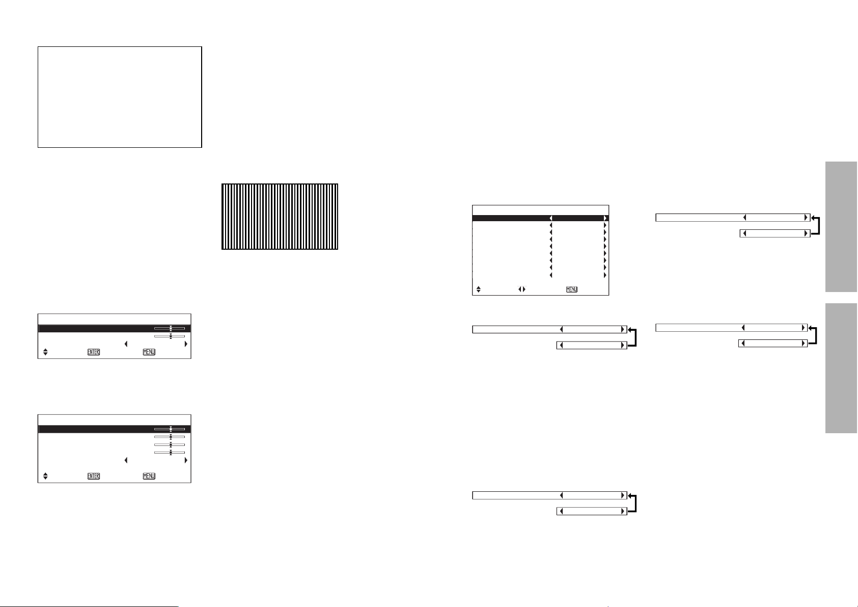
Periodic striped pattern interference
(noise) may occur when a striped
pattern such as the one below is
projected. If this happens, use the
I and H buttons to adjust so that
any such noise is minimised.
CLOCK PHASE
(PC only)
Adjust the DOT CLOCK setting first
before carrying out this adjustment.
Use the I and H buttons to adjust
so that the noise level is least
noticeable.
NOTE:
B If signals with a dot clock
frequency of 100 MHz or higher
are being input, interference may
not be completely eliminated
when the DOT CLOCK and
CLOCK PHASE adjustments are
carried out.
When the input signal is from a
PC, first select AUTO SETUP and
then press the ENTER button to
initiate automatic positioning.
If the optimum setting is not
obtained when AUTO SETUP is
carried out, adjust by the following
procedure.
ASPECT
Refer page 30.
AUTO SETUP
(PC only)
HORIZONTAL POSITION,
VERTICAL POSITION, DOT
CLOCK and CLOCK PHASE are
matched to the input signal and are
automatically adjusted.
NOTE:
B When the ASPECT is set to V-
SCROLL (page 30), AUTO
SETUP cannot be performed.
POSITION
H-POSITION 0
V-POSITION 0
ASPECT 16:9
SELECT
ENTER ESC
POSITION
H-POSITION 0
V-POSITION 0
DOT CLOCK 0
CLOCK PHASE 0
ASPECT 4:3
AUTO SETUP
SELECT
ENTER ESC
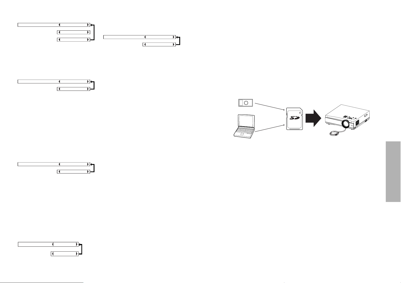
OPTION
OSD ON
NR ON
PC PRIORITY NORMAL
BACK COLOR BLACK
4:3 H-POS CENTER
FRONT/REAR FRONT
DESK/CEILING DESK
FAN CONTROL NORMAL
LAMP POWER HIGH
LAMP RUNTIME 5H
SELECT ADJ ESC
OSD ON
[
OFF
NR ON
[
OFF
PC PRIORITY NORMAL
[
WIDE
BACK COLOR BLACK
[
BLUE
Page 21
40-ENGLISH ENGLISH-41
Advanced Operation
4:3 H-POS
(4:3 aspect mode only)
This sets the horizontal positioning
of the projected image when the 4:3
aspect ratio is selected. (Refer to
page 31.)
FRONT/REAR
This setting should be changed in
accordance with the projector
setting-up method.
Set to “FRONT” when using a
normal reflective screen with the
projector positioned in front of the
screen, and set to “REAR” when
using a translucent screen with the
projector positioned behind the
screen.
DESK/CEILING
This setting should be changed in
accordance with the projector
setting-up method.
Set to “DESK” when setting up the
projector on a desk or similar, and
set to “CEILING” when suspending
the projector from the ceiling using
the ceiling bracket which is sold
separately.
FAN CONTROL
If using of this projector at high
elevations (above 1 400 m), set
FAN CONTROL to “HIGH”.
LAMP POWER
This setting changes the lamp
brightness. When set to “LOW”, the
luminance of the lamp is reduced,
but the projector uses less power,
and the operating noise is also
reduced.
The LOW position is recommended
for narrow rooms where a high
picture luminance is not essential or
for watching movies.
LAMP RUNTIME
This setting displays the usage time
for the lamp unit which is currently
being used.
NOTE:
B The lamp’s operating life varies
depending on the usage
conditions (such as the LAMP
POWER setting and the number
of times the power is turned on
and off).
SD memory card
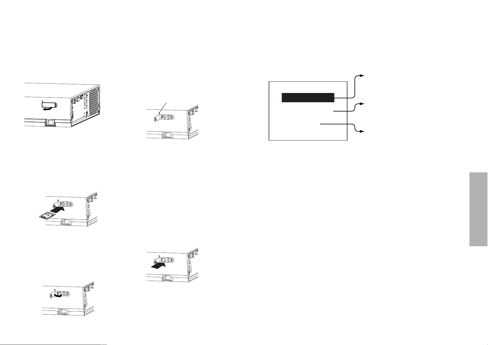
What is the SD memory card (option)?
The SD memory card is a semiconductor memory which at 24 mm x 32 mm
x 2.1 mm is about the size of a postage stamp. It is a next-generation
recording medium which can be used instead of conventional storage
devices such as MDs (mini discs), CDs (compact discs) and cassette tapes.
In addition, it allows data to be repeatedly recorded, played and erased. The
projector can be used to play computer image files, video images (still
pictures) and moving pictures using the SD memory card.
Data that can be played back
Still image data
B DCF compliant still image data (See page 64 for details on DCF
compliance.)
Moving image data
B MPEG4 movie data (audio: G.726 compliant)
However, only files in ASF format can be played back.
Note when using SD memory cards
Do not turn off the projector’s power or remove an SD memory card from the
projector while the SD memory card is in use (while the access indicator is
flashing). (See page 42.) If this is not observed, corruption of the data on the
SD memory card may occur.
16
MB
Still image data
Moving image data
Record:
Still image data
Moving image data
Play back:
Digital
camera
Computer
4:3 H-POS CENTER
[
RIGHT
[
LEFT
FRONT/REAR FRONT
[
REAR
DESK/CEILING DESK
[
CEILING
LAMP POWER HIGH
[
LOW
FAN CONTROL NORMAL
[
HIGH
Page 22
42-ENGLISH ENGLISH-43
Advanced Operation
Inserting and removing the SD memory card
About the SD menu
The still image data and moving image data that is stored on SD memory
cards can be played back using the SD menu.
Displaying the SD menu
Press the SD button to change the display to the SD CARD screen.
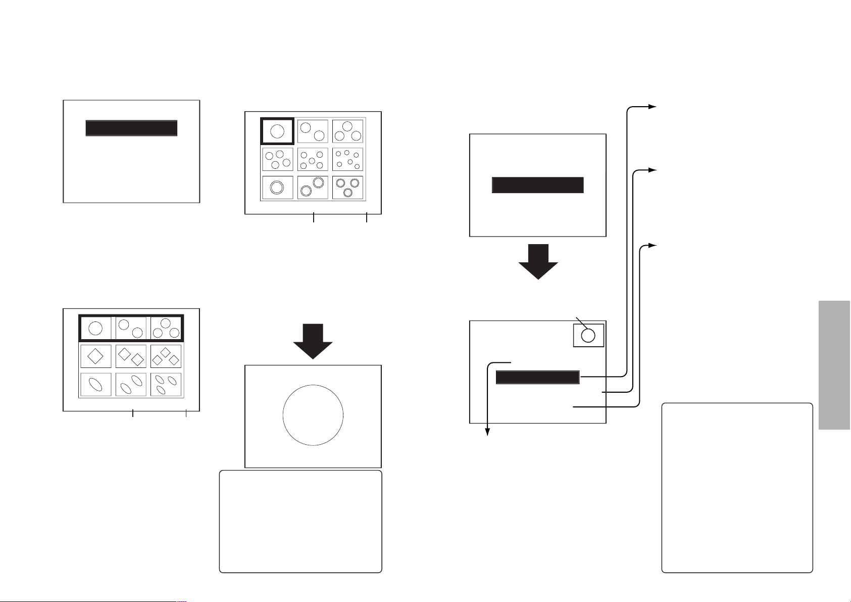
Inserting the SD
memory card
Insert the SD memory card so that it
is facing the correct way.
# Open the slot cover at the side
of the projector.
$ Insert the SD memory card as
shown in the illustration below.
Insert the SD memory card with
the label side facing upward and
so that the cut-away corner is
inserted first. Push the SD
memory card in as far as it will
go.
NOTE:
B If you try to force the SD memory
card to go in the wrong way, it
may damage the SD memory
card and the card slot.
% Close the slot cover.
Removing the SD
memory card
# Open the slot cover.
$ Check that the access indicator
at the upper-left corner of the
card slot is not flashing (the SD
memory card is not being
accessed).
NOTE:
B Always be sure to check that the
access indicator is not flashing
before removing the SD memory
card. If the SD memory card is
removed while the access
indicator is flashing, the data
stored on the SD memory card
may become corrupted.
% Push in the middle of the SD
memory card. (The SD memory
card will protrude slightly.)
& Remove the card.
' Close the slot cover.
Access lamp
PICTURE (page 44)
This lets you play back still image
data.
SLIDE SHOW (page 45)
This lets you play back still image
data in a certain order.
VIDEO (page 49)
This lets you play back moving
image data.
B If the SD menu is not displayed when the SD button is pressed,
—press the SD MENU button repeatedly until it is displayed or
—the previous menu screen or image on an SD CARD screen may be
displayed or played back.
NOTE:
B When the SD CARD screen is selected, the SD MENU button can be used
to return to a previous screen (up to the SD menu shown above).
PICTURE
SLIDE SHOW
VIDEO
Page 23
44-ENGLISH ENGLISH-45
Advanced Operation
Playing back still images
The PICTURE option lets you play back still image data.
Slide playback of still images
“SLIDE SHOW” lets you play back still images in a certain order using one of
three available playback methods. Use the
F and G
buttons to select an
item, and then press the ENTER button. Use the
I and H
buttons to change
the setting for the selected item.
# Use the F and G buttons to
select “PICTURE”, and then
press the ENTER button.
B If there is no still image data that
can be played back, the following
screen is not displayed.
$ Use the F and G buttons to
select the folder that contains
the still image data that you
would like to play back, and
then press the ENTER button.
(A)Number of selected folder
(B)Folder number/Total number
of folders
B Up to a maximum of three still
images that are saved in the
folder can be displayed in a
single row. If there are four or
more folders, use the F and G
buttons to scroll through the
pages.
Use the F and G buttons to
select “SLIDE SHOW”, and then
press the ENTER button.
SETTING (page 46)
This lets you set whether the slide
playback is to be automatically
continuous (automatic playback) or
whether it can be switched manually
(manual playback), and also lets
you edit the user settings for
“USER”.
ALL FILE
If you press the ENTER button,
all still images that are stored on
the SD memory card are played
back in order.
FOLDER
If you use the I and H buttons to
select the folder to be played back
and then press the ENTER button,
all still images in the selected
folder are played back in order.
USER
If the user selects the desired still
images, the still images that were
selected by the user can be played
back in order. When using user
playback, you must select the still
images to be played back using the
“USER” command in the
“SETTING” screen. When “USER”
is selected, use the I and H
buttons to select the user settings,
and then press the ENTER button
to start user playback.
<
Button functions during slide playback
>
B Pause/cancel automatic
playback ....... ENTER button
The following buttons can be
used while manual playback or
automatic playback is paused.
B Play back next image
................................ H button
B Play back previous image
.................................I button
B Rotate images
...................
F and G
buttons
B
Return to still image selection
screen
........ SD MENU button
% Use the F, G, I and H
buttons to select the still image
to be enlarged, and then press
the ENTER button.
(C)File name of selected still
image
(D)
Number of selected still
image/Total number of still images
B
If there are 10 or more still images
in a folder, use the F and G
buttons to scroll through the pages.
<
Button functions during still image playback
>
B
Play back next image
... H button
B Play back previous image
.................................... I button
B Rotate images
.......................
F and G
buttons
B Return to still image selection
screen .......... SD MENU button
(A) (B)
(C) (D)
PICTURE
SLIDE SHOW
VIDEO
SELECT ITEM
100
SETTING
ALL FILE
FOLDER
USER
The still image that will be the first
image to be played back for the
selected item will be displayed.
PICTURE
SLIDE SHOW
VIDEO
1/3100
1/11100-0001
Page 24
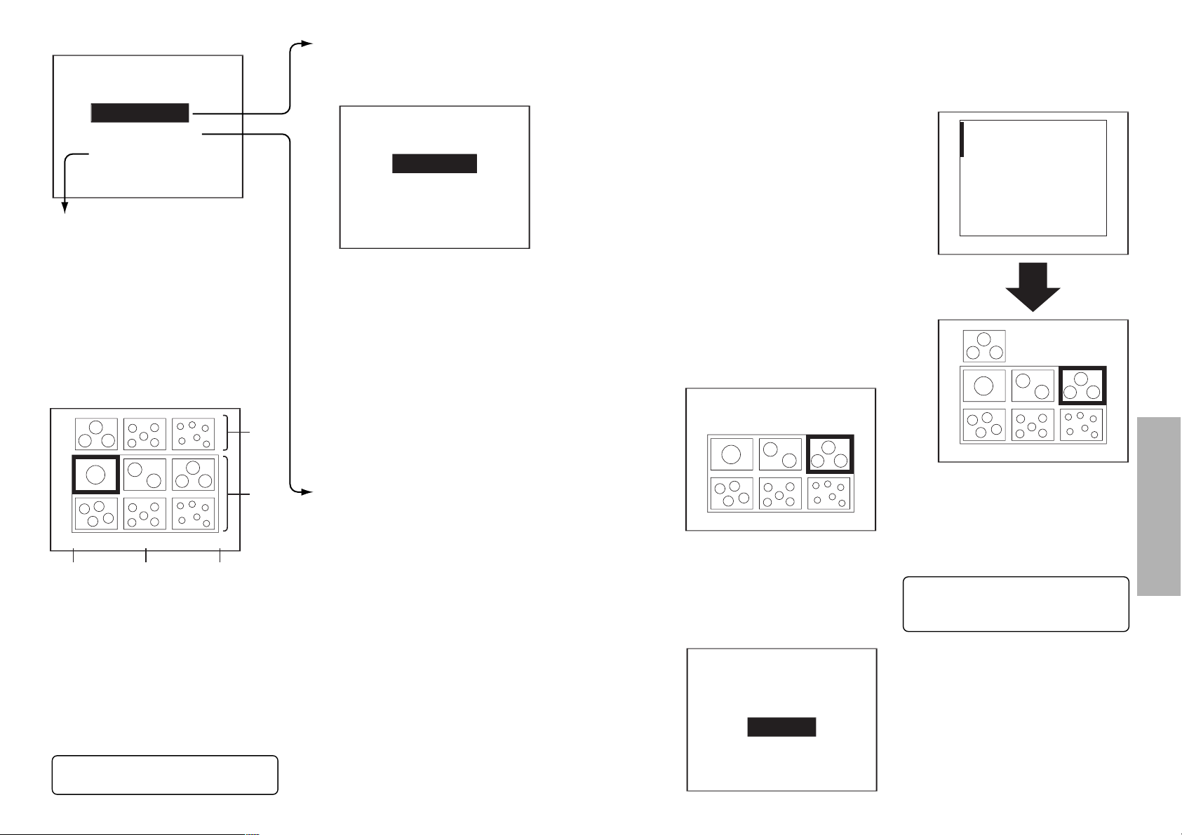
46-ENGLISH ENGLISH-47
Advanced Operation
SETTING1
MANUAL MODE
NEW
USER SET
AUTO MODE
SETTING
USER SET
If adding settings for a new user, use the
I and H buttons to select “NEW” and
then press the ENTER button. The user
setting edit screen will then be displayed.
If you would like to change the settings
for an existing user, use the I and H
buttons to select the user setting file (0 -
9) that you would like to change, and
then press the ENTER button.
User setting edit screen
(A)Still images set by user (this
row is blank for new users)
(B)Still images that are available
for setting by the user
(C)Playback time and rotation
angle for selected still image
(D)File name of selected still
image
(E)
Number of selected still
image/Total number of still images
(D) (E)(C)
(A)
(B)
See the next page for details on
how to edit user settings.
AUTO MODE
The still images are played back
automatically in order according to
the following setting.
“
REPEAT
”
ENTER button
Use the I and H buttons to select
how many times automatic playback
is to be repeated.
“
INTERVAL
”
Use the I and H buttons to select
the time interval (seconds) between
playback of each still image.
* Once you have made the required
settings, press the ENTER button.
MANUAL MODE
During slide playback, press the I
button to play back the next still
image, and press the H button to
play back the previous still image.
NOTE:
B When editing the user settings,
slide playback settings that
have not been created using
this projector cannot be edited.
Editing user settings
You can use the user setting edit
screen that is displayed when you
select “SETTING” during slide
playback on the previous page to add,
move and delete still images from the
list of images for slide playback and
also to change playback settings.
Adding and moving images
You can select still images that are
saved on the SD memory card and add
them to the user settings, and also
change the order of the still images
that have been selected in the user
settings.
# Use the F, G, I and H buttons
to select the still images to be
added or moved, and then press
the ENTER button.
B When moving images, only
images that have already been
added to the user settings can be
moved.
$ Select “ADD” or “MOVE” and
then press the ENTER button.
% Use the F, G, I and H buttons
to move the cursor (|) to the
place where the image is to be
added or moved, and then press
the ENTER button.
Repeat the procedure from step # to
add or move additional images.
SETTING2
REPEAT
INTERVAL
1
1
See the following page for
details on how to change
settings and delete images.
,
,
1/11100-00011,0
,
EDIT
SETTING
ADD
MOVE
DELETE
1/11100-00011,0
,
1/11100-00011,0
Page 25
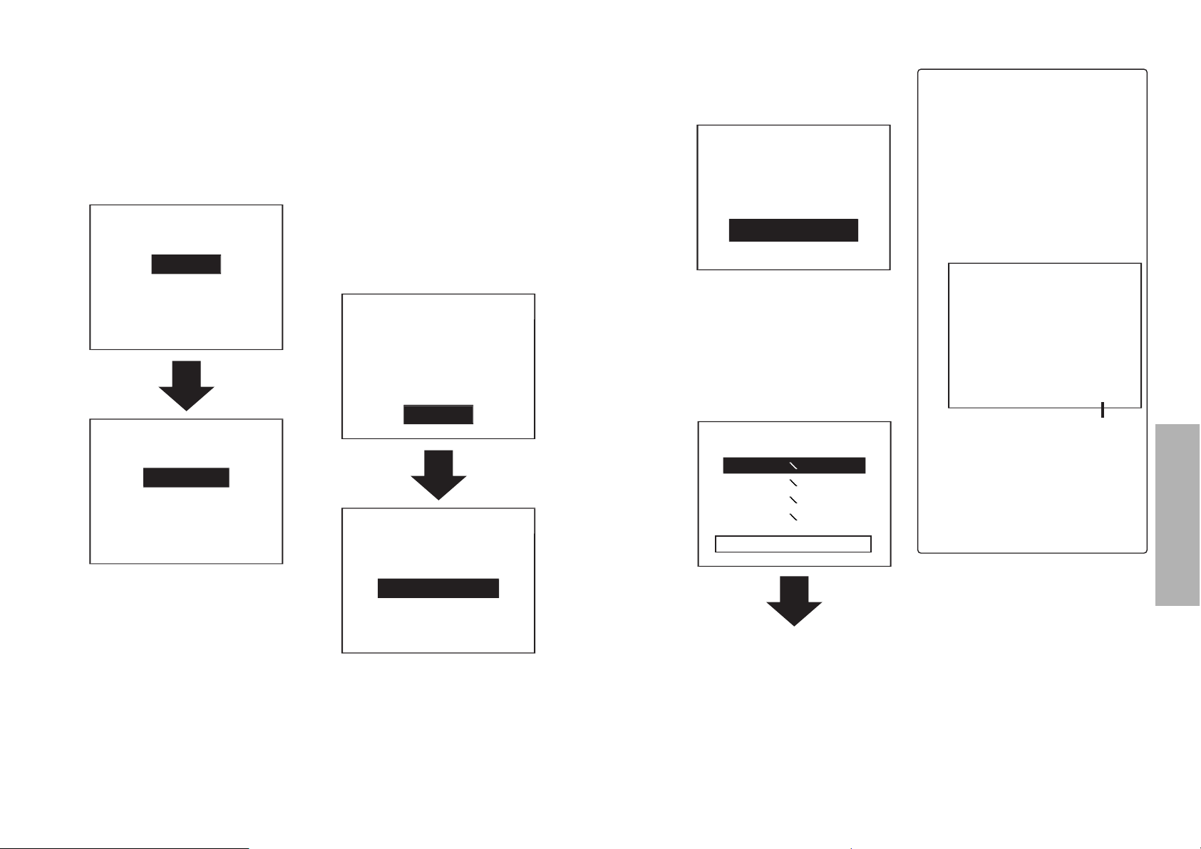
48-ENGLISH ENGLISH-49
Advanced Operation
SETUP
This describes how to set the playback
interval and angle of rotation for still
images in the user settings.
# Use the F, G, I and H
buttons to select a still image
from the user settings, and
then press the ENTER button.
$ Select “SETTING” and then
press the ENTER button.
“INTERVAL
”
Use the I and H buttons to select
the time interval (seconds) between
playback of each still image.
“
ROTATE
”
Use the I and H buttons to select the
angle of rotation for the still image during
playback. This lets you correct the position
of sideways images during playback.
* Once you have made the required
settings, press the ENTER button.
NOTE:
B
If no setting value for the playback
interval is displayed, the still images
will be played back at the interval set
for automatic playback on page 46.
B
The setting screen can also be
displayed by selecting a still image and
then pressing and holding the ENTER
button for one second or more.
DELETE
This describes how to delete
images from the user settings.
#
Use the F, G, I and H buttons
to select the still image to be
deleted from the user settings,
and then press the ENTER button.
$ Select “DELETE” and then
press the ENTER button.
“USER FILE
”
This deletes the user settings that are
currently being edited.
“100-0001”(File name of selected
still image)
This lets you delete only the selected
still image.
“CANCEL
”
This cancels the delete operation.
SETTING
0
1
EDIT
SETTING
ADD
MOVE
DELETE
INTERVAL
ROTATE
100-0001
DELETE
USER FILE
100-0001
CANCEL
EDIT
SETTING
ADD
MOVE
DELETE
0
Playing back moving images
# Use the F and G buttons to
select VIDEO and then press
the ENTER button.
B If there is no moving image data
that can be played back, the
following screen is not displayed.
$ Use the F and G buttons to
select the moving image data
that you would like to play
back, and then press the
ENTER button.
The moving image data will then be
played back.
<Button functions during
moving image playback>
Fast-forward playback...H button
Fast-rewind playback ....I button
Play back next movie.....G button
Play back previous movie
....F button
Pause/cancel pause
...
ENTER button
Stop playback
...
Press the ENTER button for 1 second or more
Display/hide playback time
...........................SD TIME button
Select moving image file
.........................SD MENU button
If you press the
I button during
movie playback, then playback will
start again from the beginning of
the current movie.
NOTE:
B
Images containing fast movement
may appear to pause momentarily
(frame dropout) or they may appear
as mosaic patterns, but this is normal.
B
If the projector has been used to enlarge
the images, some movie data may appear
lower in resolution, but this is normal.
B During fast-forward playback and
rewind playback, each still image
is played back in the same order.
Playback time display
PICTURE
SLIDE SHOW
VIDEO
PLAY FILE
PRL001 MOL001
PRL001 MOL002
PRL001 MOL003
PRL001 MOL004
2002/07/01 07:00:00
00:01:00
Page 26
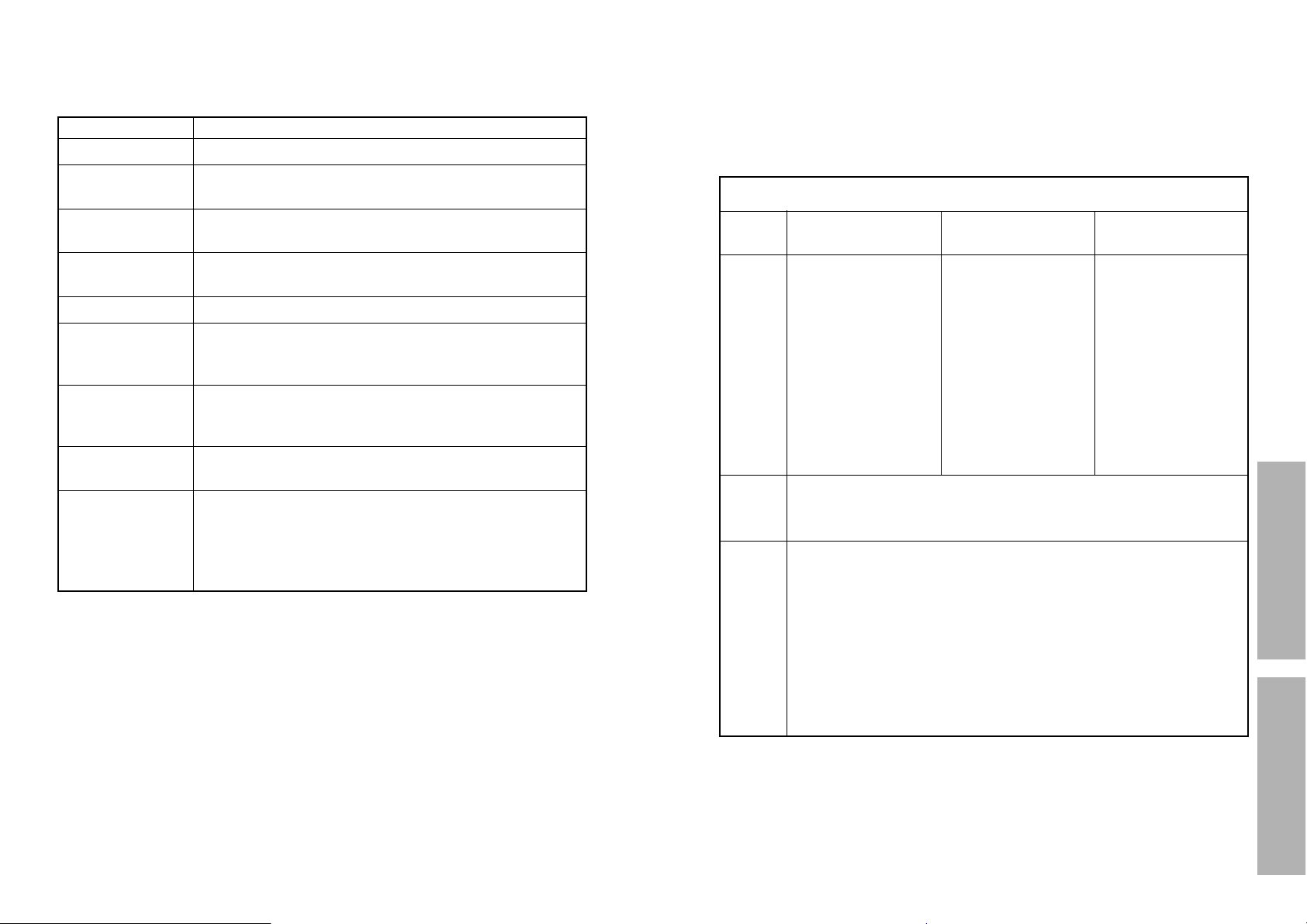
50-ENGLISH ENGLISH-51
Advanced OperationOthers
Indicators
There are two indicators on the control panel of the projector which give
information about the operating condition of the projector. These indicators
illuminate or flash to warn you about problems that have occurred inside the
projector, so if you notice that one of the indicators is on, turn off the power
and check the table below for the cause of the problem.
Problem
Indicator
display
Flashing (red)
(Lamp unit on)
The surrounding
temperature or the
temperature inside
the projector has
become unusually
high.
Illuminated (red)
(Lamp unit on)
The temperature
inside the projector
has become
dangerously high, or
the temperature has
suddenly changed.
B The ventilation holes may be covered.
B The ambient temperature in the place of use may be too high.
B The air filter may be blocked.
B Uncover the ventilation holes.
B Set up the projector in a place where the temperature is
between 0 °C (32 °F) and 40 °C (104 °F) and the humidity is
between 20% and 80% (with no condensation). [If you set the
FAN CONTROL to “HIGH” (page 40), set up the projector in a
place where the temperature is between 0 °C (32 °F) and 35 °C
(95 °F) and the humidity is between 20% and 80% (with no
condensation).]
B Turn off the MAIN POWER switch by following the procedure
on page 23, and then clean the air filter (refer to page 53).
Possible
cause
Remedy
The surrounding
temperature or the
temperature inside
the projector has
become dangerously
high, causing the
lamp unit to be
automatically shut
off.
Flashing (red)
(Lamp unit off)
TEMP indicator
Error displays
Errors may be displayed while using an SD memory card. If an error occurs,
check the following table for a description of the error.
Error display Details
NO CARD
B There is no SD memory card inserted.
UNFORMAT
B The inserted card does not match the required
specifications, for example the format is different.
DATA ERROR
B The data is not compatible and cannot be played
back.
WRITE ERROR
B The data could not be saved onto the card. Check if
the SD memory card is write-protected, or if it has
enough free space available.
ERROR
B If “ERROR” is displayed instead of a thumbnail
image, it means that the image cannot be displayed
because there is no data or the data is incompatible.
?
B If “?” is displayed instead of a thumbnail image, it
means that only the thumbnail data cannot be found.
UNEXPECTED
ERROR
B An error occurred during an operation. If the problem
cannot be reset by pressing the SD MENU button,
turn off the projector’s power while referring to
“Turning off the power” on page 23, and then turn the
power back on again.
READ ERROR
B The data cannot be read from the card.
NO DATA
B The SD memory card does not contain any data that
can be played back by the projector.
NOTE:
B Press the SD MENU button to clear an error display.
B A 2-digit error code will be displayed with an error display.
You may need the error code when asking for service.
Page 27
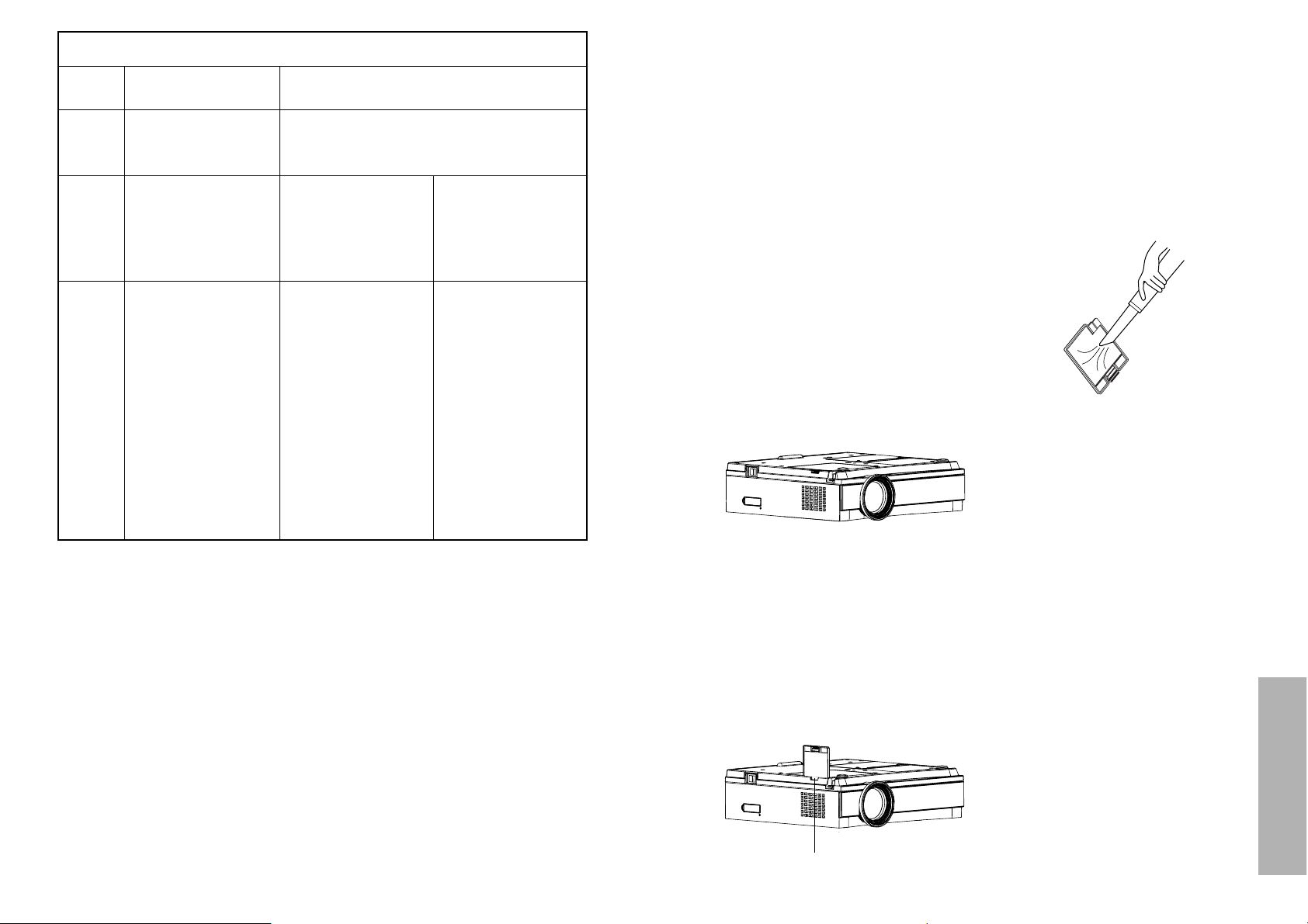
52-ENGLISH ENGLISH-53
Others
Cleaning and replacing the air filter
If the air filter becomes clogged with dust, the internal temperature of the
projector will rise, the TEMP indicator will flash and the projector power will
turn off. The air filter should be cleaned every 100 hours of use,
depending on the location where the projector is being used.
Cleaning procedure
# Turn off the MAIN POWER
switch and disconnect the
power cord plug from the wall
outlet.
Turn off the MAIN POWER switch
according to the procedure given
in “Turning off the power” on
page 23 before disconnecting the
plug from the wall outlet.
$ Gently turn the projector
upside down.
NOTE:
B Place the projector on top of a
soft cloth so that it will not
become scratched.
% Remove the air filter.
Put your fingernails under the air
filter and pull the air filter out of
the projector.
& Clean the air filter.
Use a vacuum cleaner to clean
off any accumulated dust.
NOTE:
B Be careful not to let the air filter
get sucked into the vacuum
cleaner.
' Install the air filter.
NOTE:
B Be sure to install the air filter
cover before using the projector.
If the projector is used without the
air filter cover installed, dust and
other foreign particles will be
drawn into the projector, and
malfunctions will result.
B If the dust cannot be removed by
cleaning, it is time to replace the
air filter. Please consult your
dealer. Furthermore, if the lamp
unit is being replaced, replace the
air filter at this time also.
Air filter
Remedy
Problem
Indicator
display
Flashing (red)
It is nearly time to
replace the lamp
unit.
Illuminated (red)
An abnormality has been detected in the lamp
circuit.
B Does “REPLACE
LAMP” appear on
the screen after
the projector is
turned on?
B This occurs when
the operation time
for the lamp unit is
nearing 1800
hours. (when
LAMP POWER
has been set to
“HIGH”) Ask your
dealer or an
Authorised
Service Center to
replace the lamp
unit.
Possible
cause
B The power may
have been turned
on straight away
after it was turned
off.
B Wait for a while
until the lamp unit
cools down before
turning the power
back on again.
B There may be an
abnormality in the
lamp circuit.
B Turn off the MAIN
POWER switch by
following the
procedure given
on page 23, and
then contact an
Authorised
Service Center.
LAMP indicator
NOTE:
B Be sure to turn off the MAIN POWER switch by following the procedure
given in “Turning off the power” on page 23 before carrying out any of the
procedures in the “Remedy” column.
B If the main power turns off after the TEMP indicator starts flashing, it
means that an abnormality has occurred. Please contact an Authorised
Service Center so that the necessary repairs can be made.
Page 28
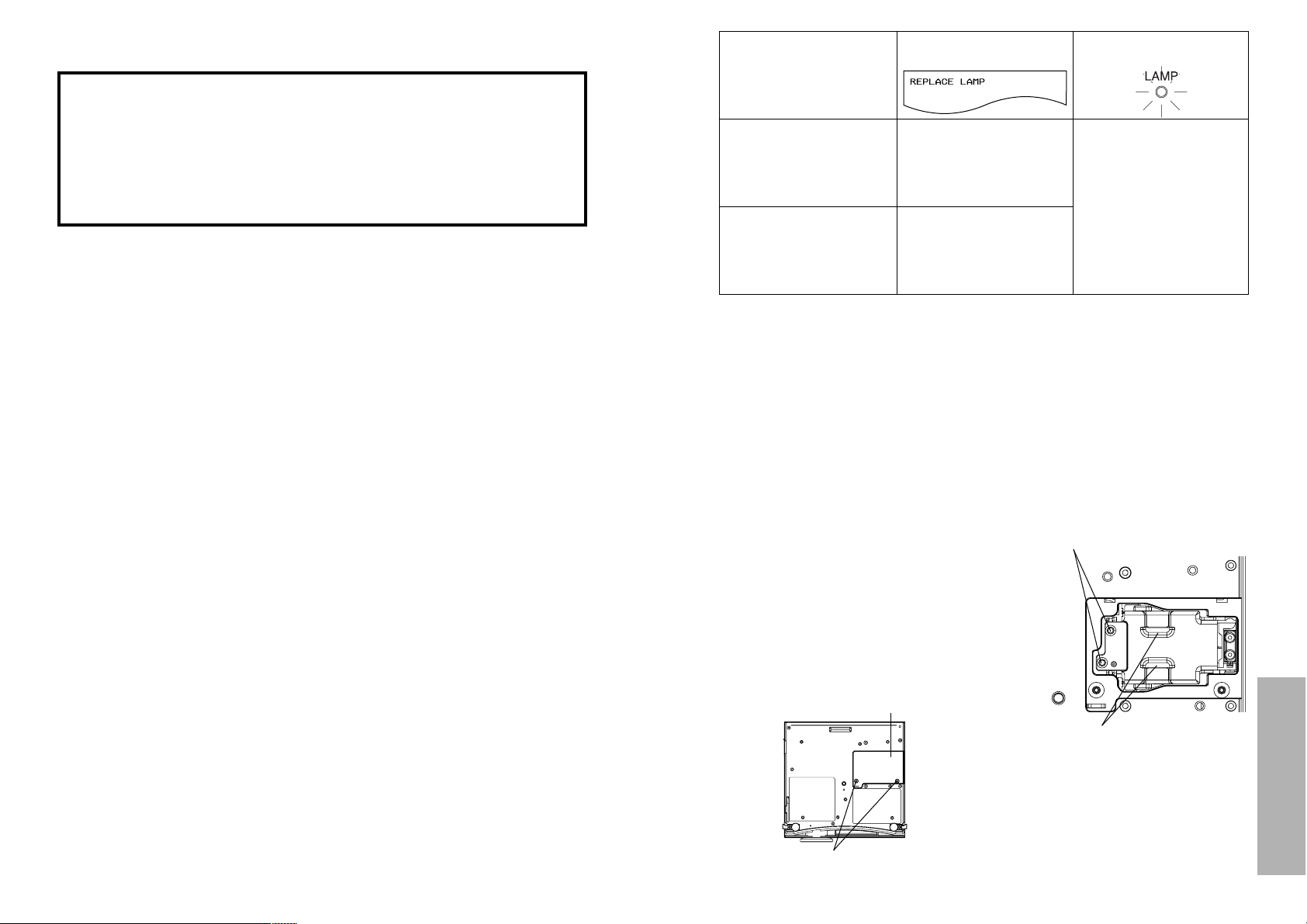
54-ENGLISH ENGLISH-55
Others
Lamp unit replacement procedure
NOTE:
B If the lamp usage time has passed 2000 hours (when LAMP POWER has
been set to “HIGH”), the projector will switch to standby mode after
approximately 10 minutes of operation. The steps * to - on the next
page should thus be completed within 10 minutes.
# Turn off the MAIN POWER
switch according to the
procedure given in “Turning off
the power” on page 23, and
then disconnect the power
cord plug from the wall outlet
and check that the area around
the lamp unit has cooled down.
$ Use a Phillips screwdriver to
turn the lamp unit cover fixing
screws at the bottom of the
projector, and then remove the
lamp unit cover from the
projector.
%
Use a Phillips screwdriver to loosen
the two lamp unit fixing screws until
the screws turn freely. Then hold
the handle of the lamp unit and
gently pull it out from the projector.
& Insert the new lamp unit while
making sure that the direction
of insertion is correct, and then
use a Phillips screwdriver to
securely tighten the lamp unit
fixing screws.
Lamp indicator warning
light
On-screen display
The lamp indicator
illuminates red even if
the projector is in
standby mode.
Displayed for 30
seconds. Pressing any
button will clear the
display.
More than 1800 hours
This display cannot be
cleared at all, no matter
which button is pressed.
More than 2000 hours
(The lamp will turn off
automatically about 10
minutes after turning on
the power.)
Lamp unit cover
Handle
Lamp unit cover
fixing screws
Lamp unit fixing screws
Replacing the lamp unit
Warning
When replacing the lamp, allow it
to cool for at least one hour
before handling it.
B The lamp cover gets very hot,
and contact with it can cause
burns.
Notes on replacing the
lamp unit
B The light generating lamp is
made of glass, so dropping it or
allowing it to hit hard objects may
cause it to burst. Be careful when
handling the lamp.
B After having removed the old
lamp, carelessly discarding it can
cause the lamp to burst. Dispose
of the lamp with the same care
that would be taken with a
fluorescent light.
B A Phillips screwdriver is
necessary for removing the lamp
unit. Make sure that your hands
are not slippery when using the
screwdriver.
Lamp unit replacement
period
The lamp is a consumable product.
Even when the full life of the bulb
has not been exhausted, the
brightness of the light will gradually
decline. Therefore periodic
replacement of the lamp is
necessary.
The intended lamp replacement
interval is 2000 hours, but it is
possible that the lamp may need to
be replaced earlier due to variables
such as a particular lamp's
characteristics, usage conditions
and the installation environment.
Early preparation for lamp
replacement is encouraged.
A lamp that has exceeded 2000
hours of use has a much greater
chance of exploding. In order to
prevent the lamp from exploding,
the lamp will be automatically shut
off when 2000 hours of use have
been reached.
NOTE:
B The usage hours explained
above are for use when the HIGH
setting has been selected for
LAMP POWER in the OPTION
menu. If the LOW setting is
selected, the brightness of the
lamp will be less and life of the
lamp can be extended.
B While 2000 hours is the intended
replacement interval, it is not a
period of time covered by
warranty.
NOTE:
B If you need the lamp replacement, please purchase the lamp unit from
our customer service.
Lamp unit product no.: ET-LAE100
CAUTION:
B Do not use any lamp unit other than the one with the product number
indicated above.
Page 29
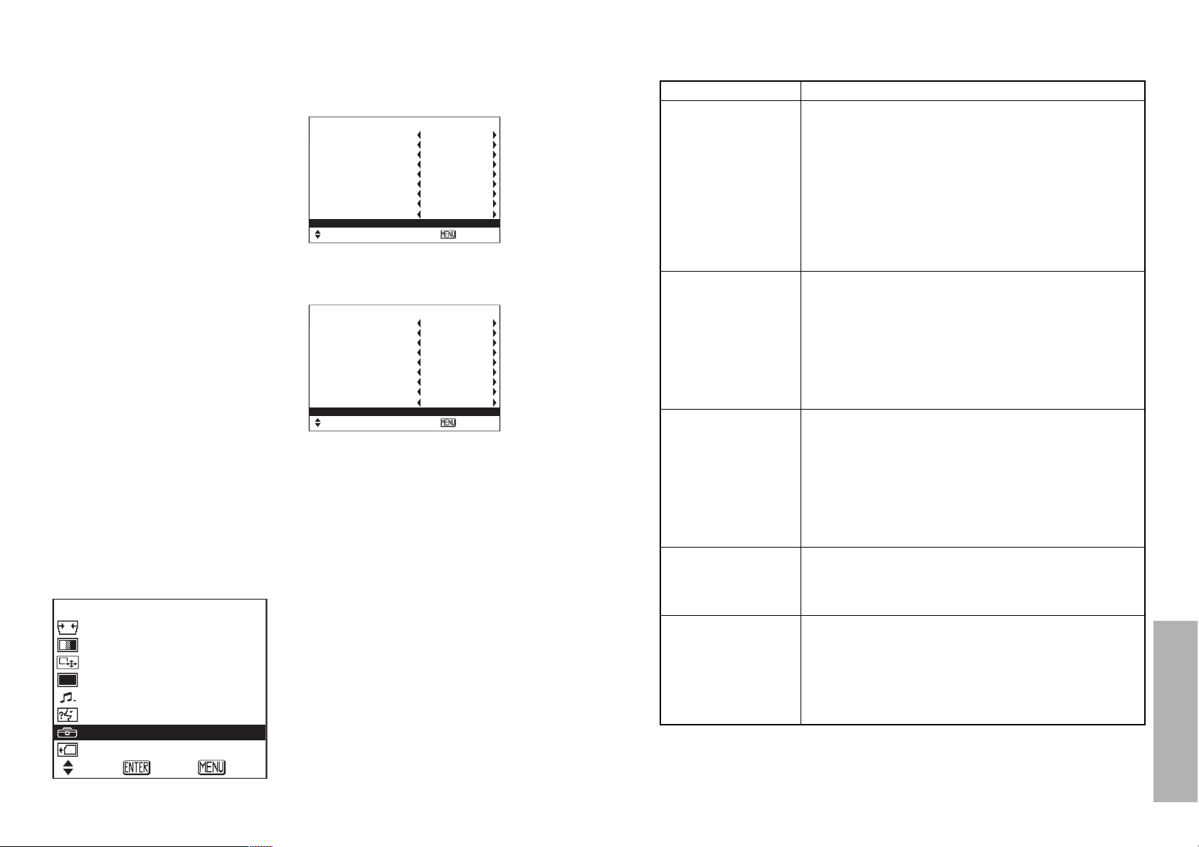
56-ENGLISH ENGLISH-57
Others
Before calling for service
Before asking for service, check the following points.
Problem Possible cause
Power does not
turn on.
No picture appears.
The picture is
fuzzy.
COLOR is too light or
TINT is poor
No sound can be
heard.
B The power cord may not be connected.
B The MAIN POWER switch is turned off.
B The main power supply is not being supplied to the
wall outlet.
B TEMP indicator is illuminated or flashing. (Refer to
page 51.)
B LAMP indicator is illuminated or flashing. (Refer to
page 52.)
B The lamp unit cover has not been securely
installed.
B The video signal input source may not be
connected properly.
B The input selection setting may not be correct.
(Refer to page 22.)
B The BRIGHT adjustment setting may be at the
minimum possible setting. (Refer to page 34.)
B The shutter function may be in use. (Refer to page
33.)
B The lens cover may still be attached to the lens.
B The lens focus may not have been set correctly.
(Refer to page 23.)
B The projector may not be at the correct distance
from the screen. (Refer to page 21.)
B The lens may be dirty.
B The projector may be tilted too much. (Refer to
page 23.)
B COLOR or TINT adjustment may be incorrect.
(Refer to pages 34 and 35.)
B The input source which is connected to the
projector may not be adjusted correctly.
B The audio signal source may not be connected
properly.
B The volume adjustment may be at the lowest
possible setting. (Refer to page 15.)
B Make sure that the MUTE function is not activated.
(Refer to page 33.)
+ Press the ENTER button to
display the OPTION screen,
and then use the F and G
buttons to select LAMP
RUNTIME.
, Press and hold the ENTER
button for approximately 3
seconds.
The “LAMP RUNTIME” will
change to “TIME RESET
[POWER OFF]”.
NOTE:
B If the MENU button is pressed,
the lamp time resetting screen
will be cancelled.
- Turn off the power.
This will reset the cumulative
usage time for the lamp unit to
zero.
Refer to page 23 for details on
how to turn off the power.
' Install the lamp unit cover, and
then use a Phillips screwdriver
to securely tighten the lamp
unit cover fixing screws.
NOTE:
B Be sure to install the lamp unit
and the lamp unit cover securely.
If they are not securely installed,
it may cause the protection circuit
to operate so that the power
cannot be turned on.
( Insert the power cord plug into
the wall outlet and then press
the MAIN POWER switch.
NOTE:
B If the POWER button on the
projector does not illuminate red
when the MAIN POWER switch is
turned on, turn the MAIN POWER
switch off again and check that
the lamp unit and the lamp unit
cover are securely installed. Then
turn the MAIN POWER switch
back on.
) Press the POWER button so
that a picture is projected onto
the screen.
* Press the MENU button to
display the MAIN MENU
screen, and then press the F
and G buttons to move the
cursor to select “OPTION”.
OPTION
OSD ON
NR ON
PC PRIORITY NORMAL
BACK COLOR BLACK
4:3 H-POS CENTER
FRONT/REAR FRONT
DESK/CEILING DESK
FAN CONTROL NORMAL
LAMP POWER HIGH
LAMP RUNTIME 1820H
SELECT ADJ ESC
MENU
KEYSTONE
PICTURE
POSITION
OPTION
OSD ON
NR ON
PC PRIORITY NORMAL
BACK COLOR BLACK
4:3 H-POS CENTER
FRONT/REAR FRONT
DESK/CEILING DESK
FAN CONTROL NORMAL
LAMP POWER HIGH
TIME RESET [POWER OFF]
SELECT ADJ ESC
SHUTTER
VOLUME
LANGUAGE
OPTION
SD MENU
SELECT ENTER EXIT
Page 30
58-ENGLISH ENGLISH-59
Others
Specifications
Power supply: 100 V–240 V ~, 50 Hz/60 Hz
Power consumption: 180 W (During standby (when fan is
stopped): Approx. 1.5 W)
Amps: 2.2 A–1.0 A
LCD panel:
Panel size (diagonal): 0.7 type (17.78 mm)
Aspect ratio: 16:9
Display method: 3 transparent LCD panels (RGB)
Drive method: Active matrix method
Pixels:
PT-AE300U: 518 400 (960 x 540) x 3 panels
PT-AE200U: 415 272 (858 x 484) x 3 panels
Lens: Manual zoom (1 - 1.2) / focus lens
F 2.0 - 2.3, f 22.0 mm - 26.2 mm
Lamp: UHM lamp (120 W)
Luminosity:
PT-AE300U: 800 lm (ANSI)
PT-AE200U: 700 lm (ANSI)
Scanning frequency: (for RGB signals):
Horizontal scanning frequency:
30 kHz–70 kHz
Vertical scanning frequency: 50 Hz–87 Hz
Dot clock frequency: Less than 100 MHz
YPBPR signals: 525i (480i), 625i, 525p (480p), 750p
(720p), 1125i (1080i)
Color system: 7 (NTSC/NTSC 4.43/PAL/PAL-M/PAL-
N/PAL60/SECAM)
Projection size: 1016 mm - 5080 mm (40˝ - 200˝)
Throw distance: 1.2 m - 7.4 m (3´11˝ - 24´3˝)
Optical axis shift: 17:1 (fixed)
Screen aspect ratio: 16:9
Installation: Front/Rear/Ceiling/Desk (Menu selection
method)
Speaker: 4 cm x 3 cm oval x 1
Max. useable volume output: 2 W (mono)
Connectors
VIDEO IN:
S2 VIDEO: Single-line, Mini DIN 4-pin
Y 1.0 V [p-p], C 0.286 V [p-p], 75 Ω
VIDEO: Single-line, RCA pin jack
1.0 V [p-p], 75 Ω
PC IN:
RGB: Single-line D-SUB HD 15-pin (female)
R.G.B.: 0.7 V [p-p], 75 Ω
G.SYNC: 1.0 V [p-p], 75 Ω
HD/SYNC: TTL high impedance, automatic
plus/minus polarity compatible
VD: TTL high impedance, automatic
Remote control unit
does not operate.
The picture does not
display correctly.
Picture from
computer does not
appear
Problem Possible cause
B The battery may be weak.
B The battery may not be inserted correctly. (Refer to
page 17.)
B The remote control signal receptor on the projector
may be obstructed. (Refer to page 17.)
B The remote control unit may be out of the
operation range. (Refer to page 17.)
B The correct input signal may not be selected.
(Refer to page 22.)
B The signal format (TV system) may not be set
correctly. (Refer to page 35.)
B There may be a problem with the video tape or
other signal source.
B A signal which is not compatible with the projector
may be being input. (Refer to page 61.)
B The cable may be too long.
B The external video output for the laptop computer
may not be set correctly.
(You may be able to change the external output
settings by pressing the [Fn]+[F3] or [Fn]+[F10]
keys simultaneously. The actual method varies
depending on the type of computer, so refer to the
documentation provided with your computer for
further details.)
Page 31
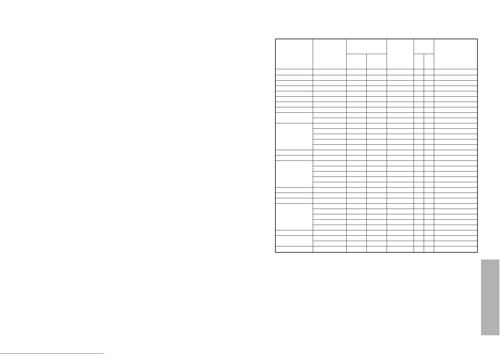
60-ENGLISH ENGLISH-61
Others
Appendix
List of compatible signals
*1 The “i” appearing after the resolution indicates an interlaced signal.
*2 The following symbols are used to indicate picture quality.
AA Maximum picture quality can be obtained.
A Signals are converted by the image processing circuit before picture
is projected
B Some loss of data occurs to make projection easier.
720 x 480i 15.734 59.940 A A Video/S-Video
720 x 576i 15.625 50.000 AA A Video/S-Video
720 x 480i 15.734 59.940 13.500 A A YPBPR
720 x 576i 15.625 50.000 13.500 AA A YPBPR
720 x 483 31.469 59.940 27.000 A A YPBPR
1 920 x 1 080i 33.750 60.000 74.250 AA A YPBPR/PC
1 920 x 1 080i 28.125 50.000 74.250 AA A YPBPR/PC
1 280 x 720 45.000 60.000 74.250 A A YPBPR
640 x 400 31.469 70.086 25.175 A A PC
640 x 400 37.861 85.081 31.500 A A PC
640 x 480 31.469 59.940 25.175 A AA PC/DV1
640 x 480 35.000 66.667 30.240 A AA PC
640 x 480 37.861 72.809 31.500 A AA PC
640 x 480 37.500 75.000 31.500 A AA PC
640 x 480 43.269 85.008 36.000 A AA PC
720 x 400 37.927 85.038 35.500 A A PC
856 x 480 30.057 60.114 31.500 A AA PC/DV1
800 x 600 35.156 56.250 36.000 A A PC
800 x 600 37.879 60.317 40.000 A A PC/DV1
800 x 600 48.077 72.188 50.000 A A PC
800 x 600 46.875 75.000 49.500 A A PC
800 x 600 53.674 85.061 56.250 A A PC
832 x 624 49.725 74.550 57.283 A A PC
1 072 x 600 37.287 59.947 51.382 A A PC/DV1
1 280 x 720 45.106 60.141 76.500 A A PC
1 024 x 768 48.363 60.004 65.000 A A PC/DV1
1 024 x 768 56.476 70.069 75.000 A A PC
1 024 x 768 60.023 75.029 78.750 A A PC
1 024 x 768 68.678 84.997 94.500 A A PC
1 024 x 768i 35.520 86.952 44.897 A A PC
1 280 x 768 45.327 56.518 76.150 A A PC/DV1
1 152 x 864 63.995 71.184 94.200 A A PC
1 152 x 864 67.500 74.917 108.000 B B PC
1 152 x 870 68.681 75.062 100.000 B B PC
Display
resolution
(dots)*
1
Scanning
frequency
H
(kHz)V (Hz)
Dot clock
frequency
(MHz)
Picture
quality*
2
AE300 AE200
NTSC/M-NTSC/PAL-M/PAL60
PAL/PAL-N/SECAM
525i
625i
525p
HDTV60
HDTV50
750P
VGA400
VGA480
WIDE400
WIDE480
SVGA
MAC16
WIDE600
WIDE720
XGA
WIDE768
MXGA
MAC21
Format
Mode
plus/minus polarity compatible
COMPONENT IN:
Y: 1.0 V [p-p], 75 Ω
PB,PR (CB,CR): 0.7 V [p-p], 75 Ω
DVI-D IN (PT-AE300U only):
Single-line, DVI-D, 24-pin
AUDIO IN: Single-line 0.5 V [rms], RCA pin jack x2
(L-R)
SD memory card slot: For SD memory cards
Compatible with DCF-standard still image
data
Compatible with MPEG4 moving picture
data (audio: G.726 compliant)
Cabinet: Moulded plastic (ABS/PC)
Dimensions:
Width: 280 mm (11˝)
Height: 85.2 mm (3-11/32˝)
Length: PT-AE300U 279.7 mm (11˝) (including lens)
PT-AE200U 278.5 mm (10-15/16˝) (including lens)
Weight: 2.9 kg (6.4 lbs.)
Operating environment:
Temperature: 0 °C–40 °C (32 °F–104 °F)
[When the FAN CONTROL is set to
“HIGH” (page 40); 0 °C–35 °C (32 °F–95
°F)]
Humidity: 20%–80% (no condensation)
Certifications: UL1950, C-UL
FCC
<Remote control unit>
Power supply: 3 V DC (AAA battery x2)
Operating range: Approx. 7 m (23´) (when operated directly
in front of signal receptor)
Weight: 73.5 g (2.6 ozs.) (including battery)
Dimensions:
Width: 43 mm (1-11/16˝)
Height: 22.3 mm (7/8˝)
Length: 135 mm (5-5/16˝)
<Options>
Ceiling bracket ET-PKE300
Projection Screen ET-SR90CT(width: 1 800 mm(70"))
ET-SR70CT(width: 1 400 mm(55"))
*Specifications are subject to change without notice.
Page 32
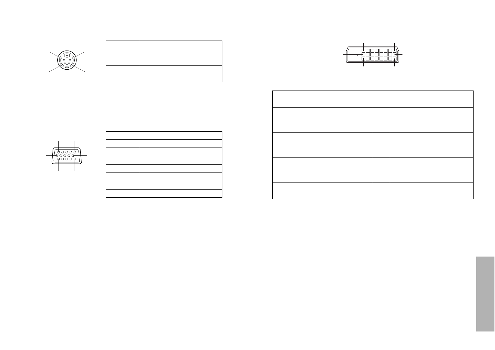
62-ENGLISH ENGLISH-63
Others
Pin No. Signal
#
Earth (Luminance signal)
Earth (Color signal)
Luminance signal
Color signal
$
%
&
B The pin layout and signal names for the RGB input connector are shown
below.
Pin No. Signal
#
R
G/G·SYNC
B
SDA
$
%
.
/
HD/SYNC
0
VD
1
SCL
Pin + is spare.
Pins &–*, , and - are for earth.
Pins . and 1 functions are only valid when
supported by the computer
#$
%&
External view
-1
#'
,(
External view
Connector pin wiring
B The pin layout and signal names for the S2 VIDEO input connector are
shown below.
B The pin assignments on the DVI-D input connector are as follows
(interface with TMDS connector on a personal computer)
View from mating side
Pin No.
Signal
Pin No.
Signal
#
T.M.D.S data 2-
/
T.M.D.S data 3+
$
T T.M.D.S data 2+
0
+5 V
%
T.M.D.S data 2/4 shield
1
Ground
&
T.M.D.S data 4-
2
Hot plug sense
'
T.M.D.S data 4+
3
T.M.D.S data 0-
(
DDC clock
4
T.M.D.S data 0+
)
DDC data
*
-
6
T.M.D.S data 5-
+
T.M.D.S data 1-
7
T.M.D.S data 5+
,
T.M.D.S data 1+
8
T.M.D.S clock shield
-
T.M.D.S data1/3 shield
.
T.M.D.S data 3-
:
T.M.D.S clock-
5
T.M.D.S data 0/5 shield
9
T.M.D.S clock+
#
*
3:
2
+
Page 33
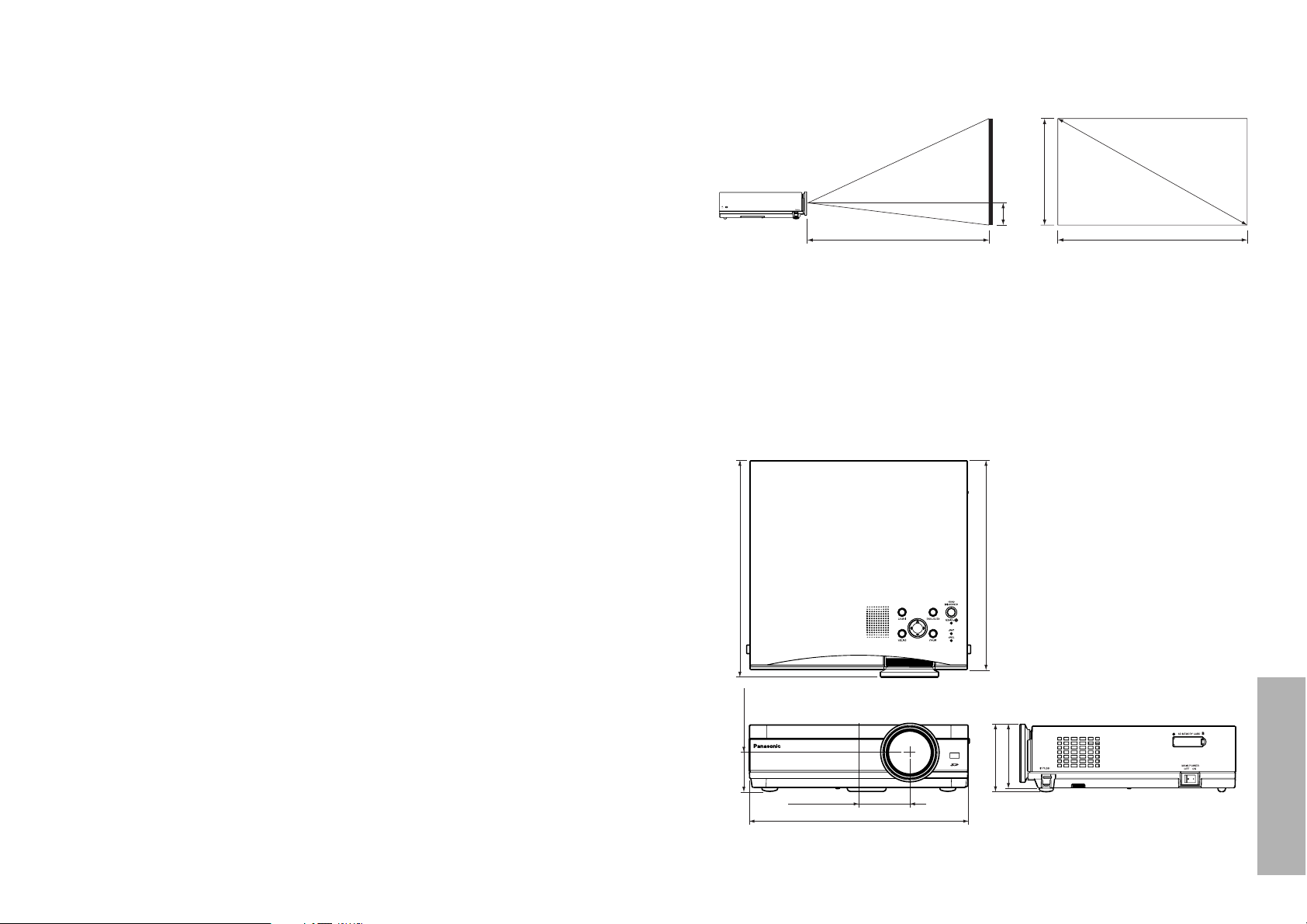
64-ENGLISH ENGLISH-65
Others
DCF standard
This projector can only play back image files which comply with the DCF
specification. The DCF specification imposes the following conditions. Image
files or folders which do not conform to these conditions cannot be
recognised by the projector.
Limits on folder names
Folders must be created as sub-folders of the DCIM folder on the SD
memory card.
B Data which is contained within any folder other than the DCIM folder
cannot be recognised.
Folder names must consist of three numerals (folder number) followed
by five alphanumeric characters. (Example: 100abcde)
B The three numerals must make up a number between 100 and 999, and
the alphanumeric characters can be taken from the following set of 37
characters: 0123456789abcdefghijklmnopqrstuvwxyz_ (No distinction is
made between upper-case and lower-case alphabetic characters.
Doublebyte characters cannot be used.)
Multiple folders using the same three-digit combination (folder number)
cannot be created.
B For example, if two folders exist named "100abcde" and "100fghij"
respectively, the projector will not recognise them.
Folder sub-hierarchies are not supported.
B For example, if a folder called "323fghij" is created as a sub-folder of the
"102abcde" folder, the projector will not be able to recognise the subfolder.
File names
File names must consist of four alphanumeric characters followed by
four numerals (file number), followed by ".jpg". (Example: abcd0001.jpg)
B The four numerals must make up a number between 0001 and 9999, and
the alphanumeric characters can be taken from the following set of 37
characters: 0123456789abcdefghijklmnopqrstuvwxyz_ (No distinction is
made between upper-case and lower-case alphabetic characters.
Doublebyte characters cannot be used.)
Multiple file names using the same four-digit combination (file number)
cannot be created.
B For example, if two files exist named "abcd0001.jpg" and "efgh0001.jpg"
respectively, the projector cannot recognise them normally.
File format
B Only JPEG image files which comply with the Exif 2.2 standard are
recognised.
Projection dimensions calculation methods
The following methods will allow you to calculate dimensions such as screen
diagonal length and projection distances. Units in all calculations are metre.
Screen Width: SW=SDx0.872
Screen Height: SH=SDx0.490
Minimum Projection Distance: LW=1.229xSD-0.0381
Maximum Projection Distance: LT=1.481xSD-0.0381
Image Lower Edge from Lens Center: H1=SW/32
Dimensions
<Units: mm (˝)>
280(11)
80.2(3-5/32)
85.2(3-11/32)
PT-AE200U: 278.5(10 15/16)
65.4(2 9/16)
49.7(1 15/16)
269(10-9/16)
PT-AE300U: 279.7(11)
16:9
SH
H1
LW/LT
SD
SW
Page 34

66-ENGLISH
Trademark acknowledgements
B The SD logo is a trademark.
B VGA and XGA are trademarks of International Business Machines
Corporation.
B Macintosh is a registered trademark of Apple Computer, Inc.
B S-VGA is a registered trademark of the Video Electronics Standards
Association.
All other trademarks are the property of the various trademark owners.
These Operating Instructions are printed on recycled paper.
Panasonic Consumer
Electronics Company,
Division of Matsushita
Electric Corporation
of America
One Panasonic Way
Secaucus
New Jersey 07094
Panasonic Sales
Company, Division of
Matsushita Electric of
Puerto Rico Inc.
(“PSC”)
Ave. 65 de Infanteria,
Km 9.5 San Gabriel
Idustrial Park, Carolina,
Puerto Rico 00985
Panasonic Canada
Inc.
5770 Ambler Drive,
Mississauga, Ontario
L4W 2T3 (905) 6245010
 Loading...