

Page 1

Philips Consumer Electronics
Technical Service Data
Service and Quality
Service Publications Dept.
One Philips Drive
P.O. Box 14810
Knoxville, TN 37914
Pg. SCHEMATIC DIAGRAMS AND PC BOARDS
1. Schematic/Circuitry Listings
2. Main Ch. - Power Supply Circuitry (A01)
3. Main Ch. - Line Deflection Circuitry (A02)
4. Main Ch. - Frame Deflection Circuitry (A03)
5. Main Ch. - Sync Circuitry (A04)
6. Main Ch. - Tuner/Video/IF Circuitry (A05)
7. Main Ch. - Video Processing Circuitry (A06)
8. Main Ch. - SIF/Audio Circuitry (A07)
9. Main Ch. - External Input Circuitry (A08)
10. Main Ch. - Audio Amplifier Circuitry (A09)
Manual 7590
Model no.: PR1906C121
First Publish: 10-09-01
Rev. Date: 04-04-00
Print Date: 18/07/2006
11. Main Ch. - Control Circuitry (A10)
12. CRT Panel Circuitry (B)
13. BTSC Stereo Circuitry (C) - ASD100 Panel
14. Main Ch. & CRT Panel PCBs (Top View)
15. Main Ch. & CRT Panel PCBs (Bottom View)
16. BTSC Sterero PCB (ASD100 Panel - Top View)
17. BTSC Sterero PCB (ASD100 Panel - Bottom View)
18. OVERALL BLOCK DIAGRAM
REFER TO SAFETY GUIDELINES
SAFETY NOTICE: ANY PERSON ATTEMPTING TO SERVICE THIS CHASSIS MUST FAMILIARIZE
HIMSELF WITH THE CHASSIS AND BE AWARE OF THE NECESSARY SAFETY PRECAUTIONS
TO BE USED WHEN SERVICING ELECTRONIC EQUIPMENT CONTAINING HIGH VOLTAGES.
CAUTION: USE A SEPARATE ISOLATION TRANSFORMER FOR THIS UNIT WHEN SERVICING
© Philips Electronics North America Corporation Visit our World Wide Web Site at http://www.forceonline.com
Page 2

Philips Consumer Electronics
Technical Service Data
Service and Quality
Service Publications Dept.
One Philips Drive
P.O. Box 14810
Knoxville, TN 37914
Manual 7590
Model no.: PR1906C121
First Publish: 10-09-01
Rev. Date: 04-04-00
Print Date: 18/07/2006
Mechanical Diagrams
REFER TO SAFETY GUIDELINES
SAFETY NOTICE: ANY PERSON ATTEMPTING TO SERVICE THIS CHASSIS MUST FAMILIARIZE
HIMSELF WITH THE CHASSIS AND BE AWARE OF THE NECESSARY SAFETY PRECAUTIONS
TO BE USED WHEN SERVICING ELECTRONIC EQUIPMENT CONTAINING HIGH VOLTAGES.
CAUTION: USE A SEPARATE ISOLATION TRANSFORMER FOR THIS UNIT WHEN SERVICING
© Philips Electronics North America Corporation Visit our World Wide Web Site at http://www.forceonline.com
Page 3
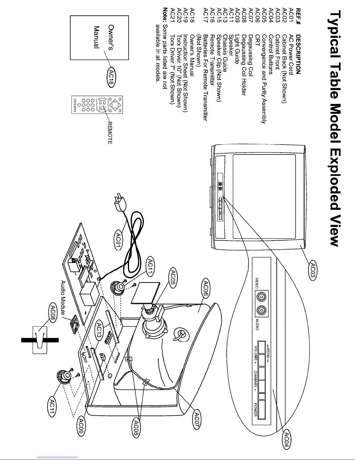
MAIN CABINET EXPLODED VIEW Page: 1 of 1
Page 4

Philips Consumer Electronics
Technical Service Data
Service and Quality
Service Publications Dept.
One Philips Drive
P.O. Box 14810
Knoxville, TN 37914
Manual 7590
Model no.: PR1906C121
First Publish: 10-09-01
Rev. Date: 04-04-00
Print Date: 18/07/2006
Troubleshooting
REFER TO SAFETY GUIDELINES
SAFETY NOTICE: ANY PERSON ATTEMPTING TO SERVICE THIS CHASSIS MUST FAMILIARIZE
HIMSELF WITH THE CHASSIS AND BE AWARE OF THE NECESSARY SAFETY PRECAUTIONS
TO BE USED WHEN SERVICING ELECTRONIC EQUIPMENT CONTAINING HIGH VOLTAGES.
CAUTION: USE A SEPARATE ISOLATION TRANSFORMER FOR THIS UNIT WHEN SERVICING
© Philips Electronics North America Corporation Visit our World Wide Web Site at http://www.forceonline.com
Page 5
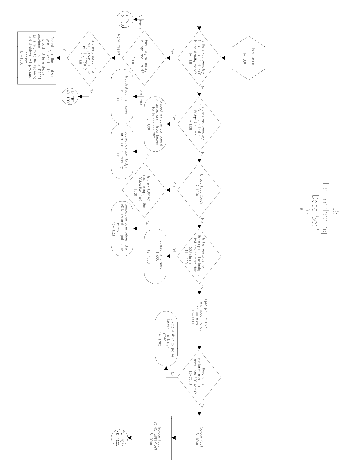
Page 6
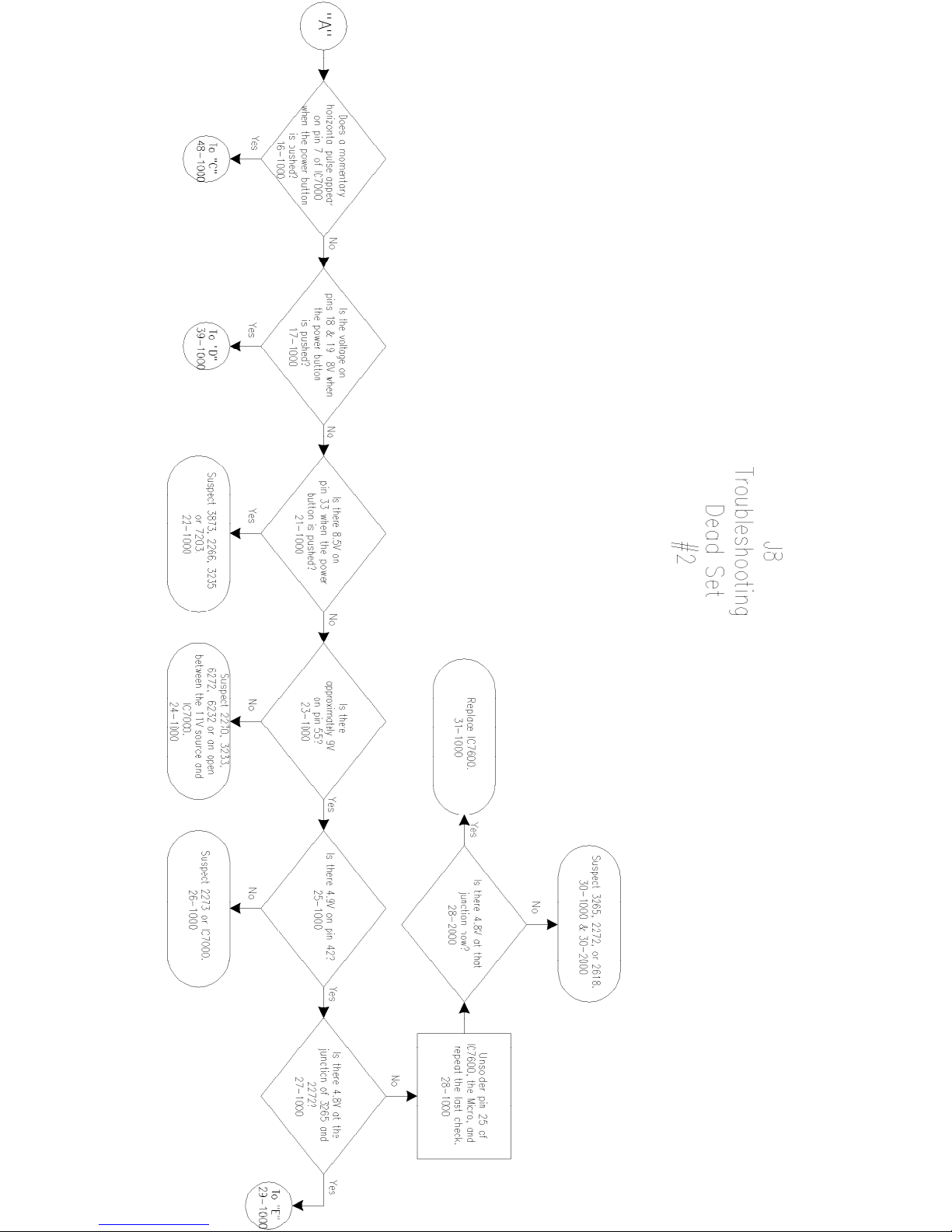
Page 7
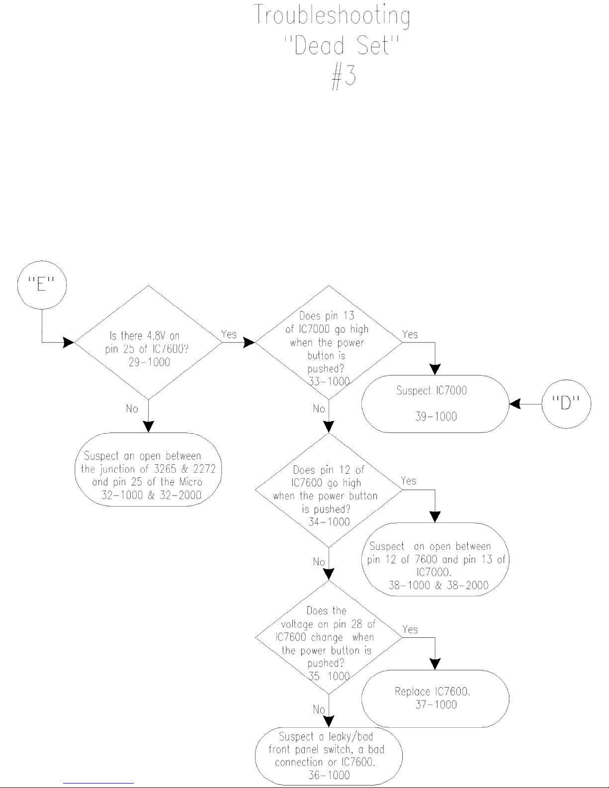
Page 8
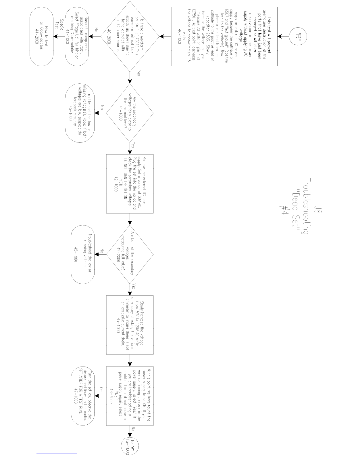
Page 9
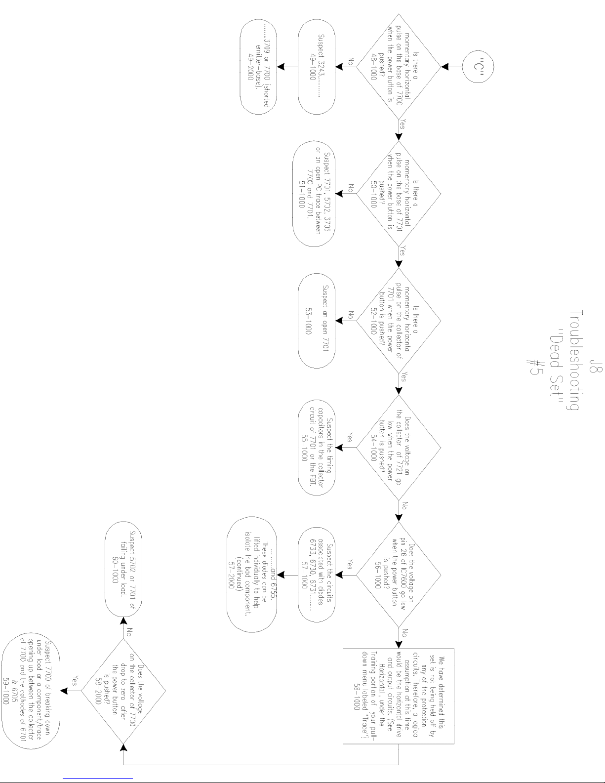
Page 10
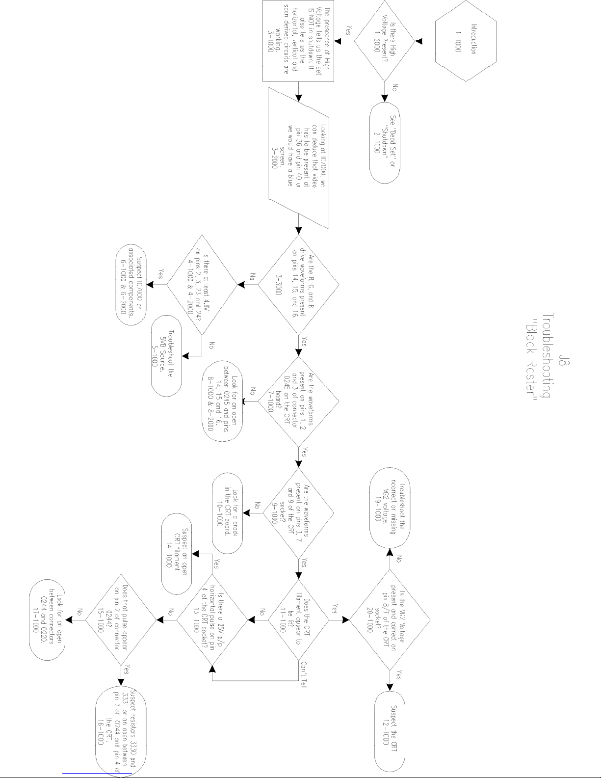
Page 11
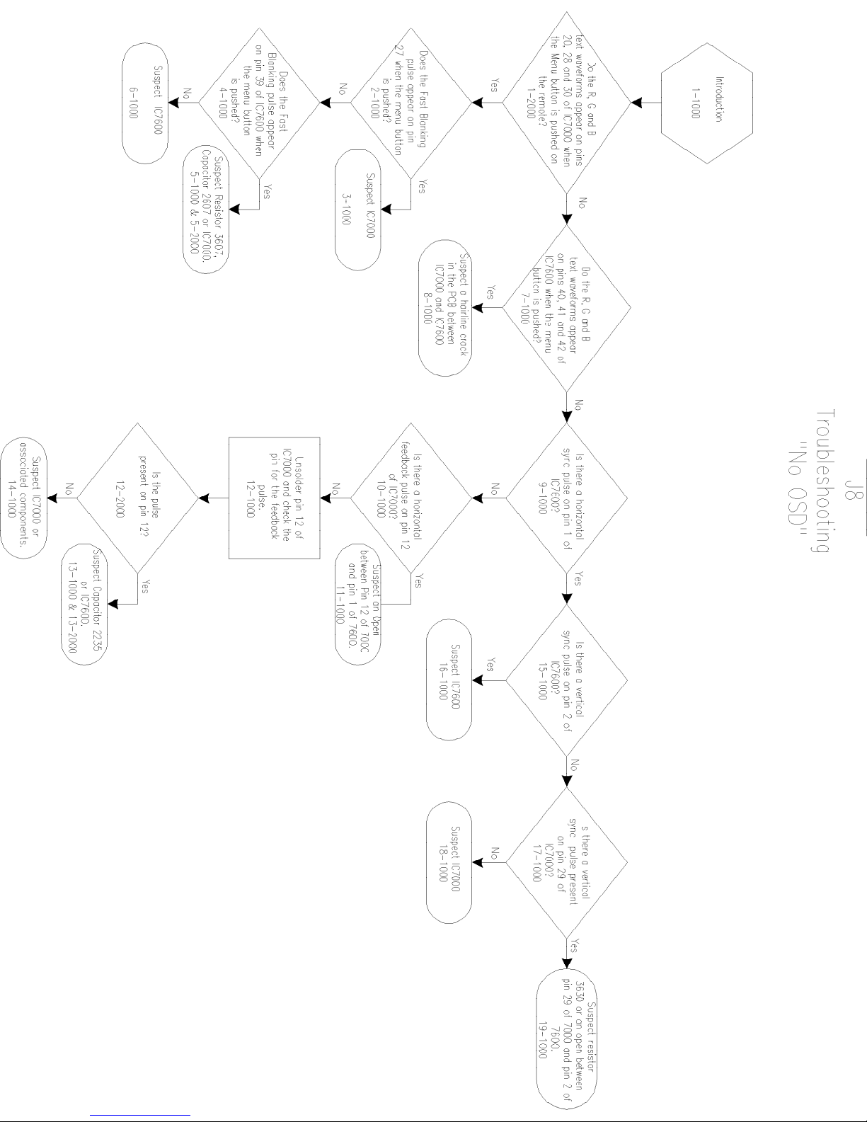
Page 12
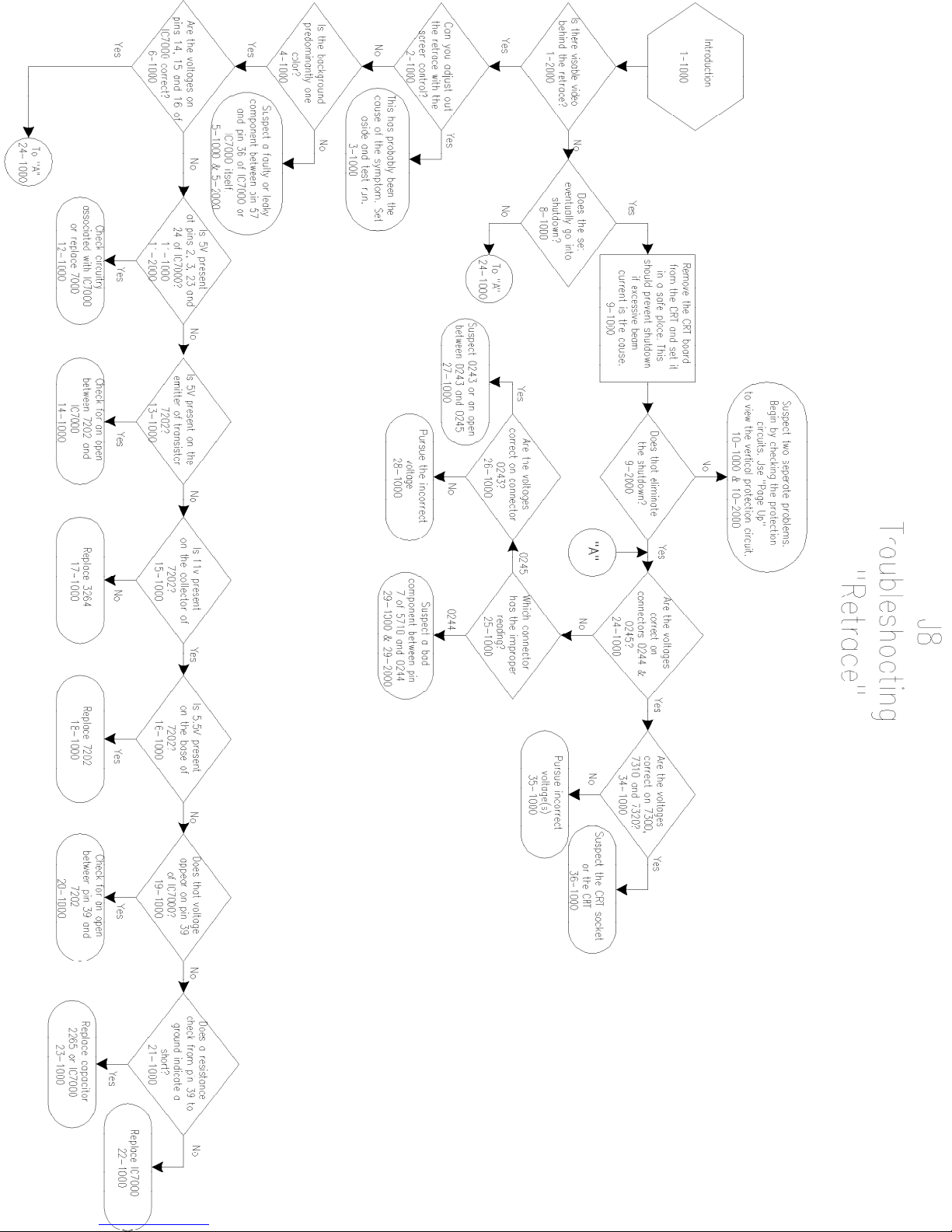
Page 13
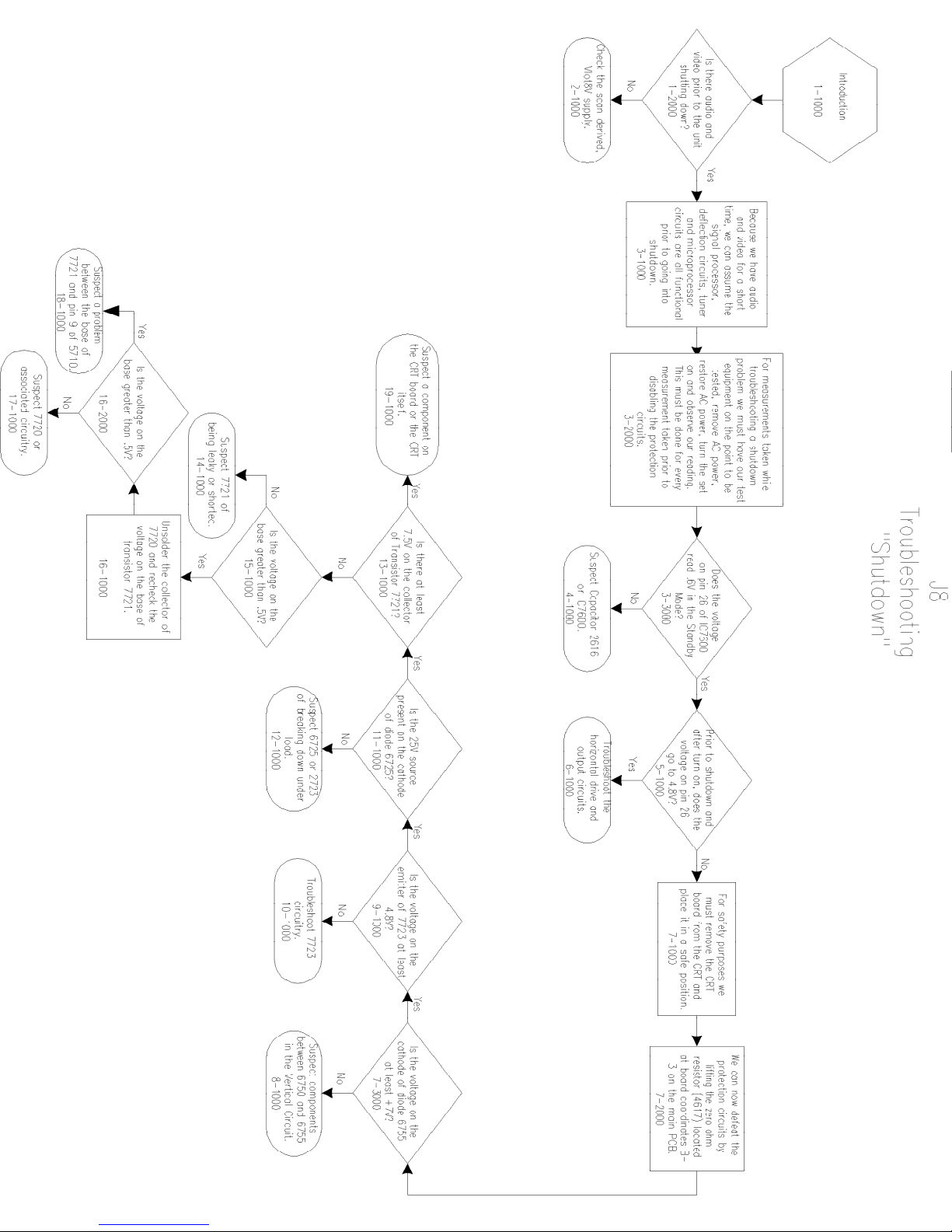
Page 14

Philips Consumer Electronics
Technical Service Data
Service and Quality
Service Publications Dept.
One Philips Drive
P.O. Box 14810
Knoxville, TN 37914
Manual 7590
Model no.: PR1906C121
First Publish: 10-09-01
Rev. Date: 04-04-00
Print Date: 18/07/2006
General Information
REFER TO SAFETY GUIDELINES
SAFETY NOTICE: ANY PERSON ATTEMPTING TO SERVICE THIS CHASSIS MUST FAMILIARIZE
HIMSELF WITH THE CHASSIS AND BE AWARE OF THE NECESSARY SAFETY PRECAUTIONS
TO BE USED WHEN SERVICING ELECTRONIC EQUIPMENT CONTAINING HIGH VOLTAGES.
CAUTION: USE A SEPARATE ISOLATION TRANSFORMER FOR THIS UNIT WHEN SERVICING
© Philips Electronics North America Corporation Visit our World Wide Web Site at http://www.forceonline.com
Page 15
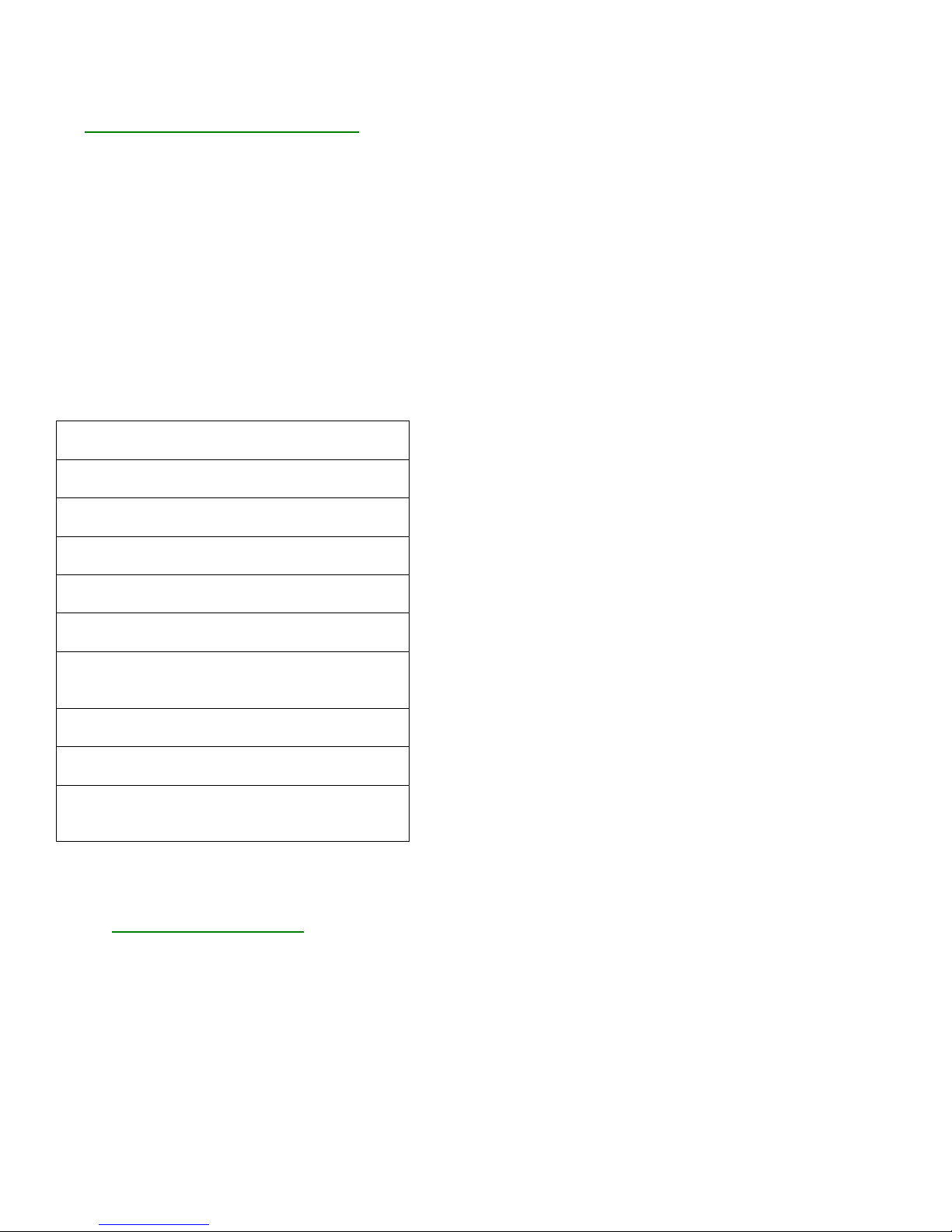
GENERAL INFORMATION
J8 Chassis - Manual 7590
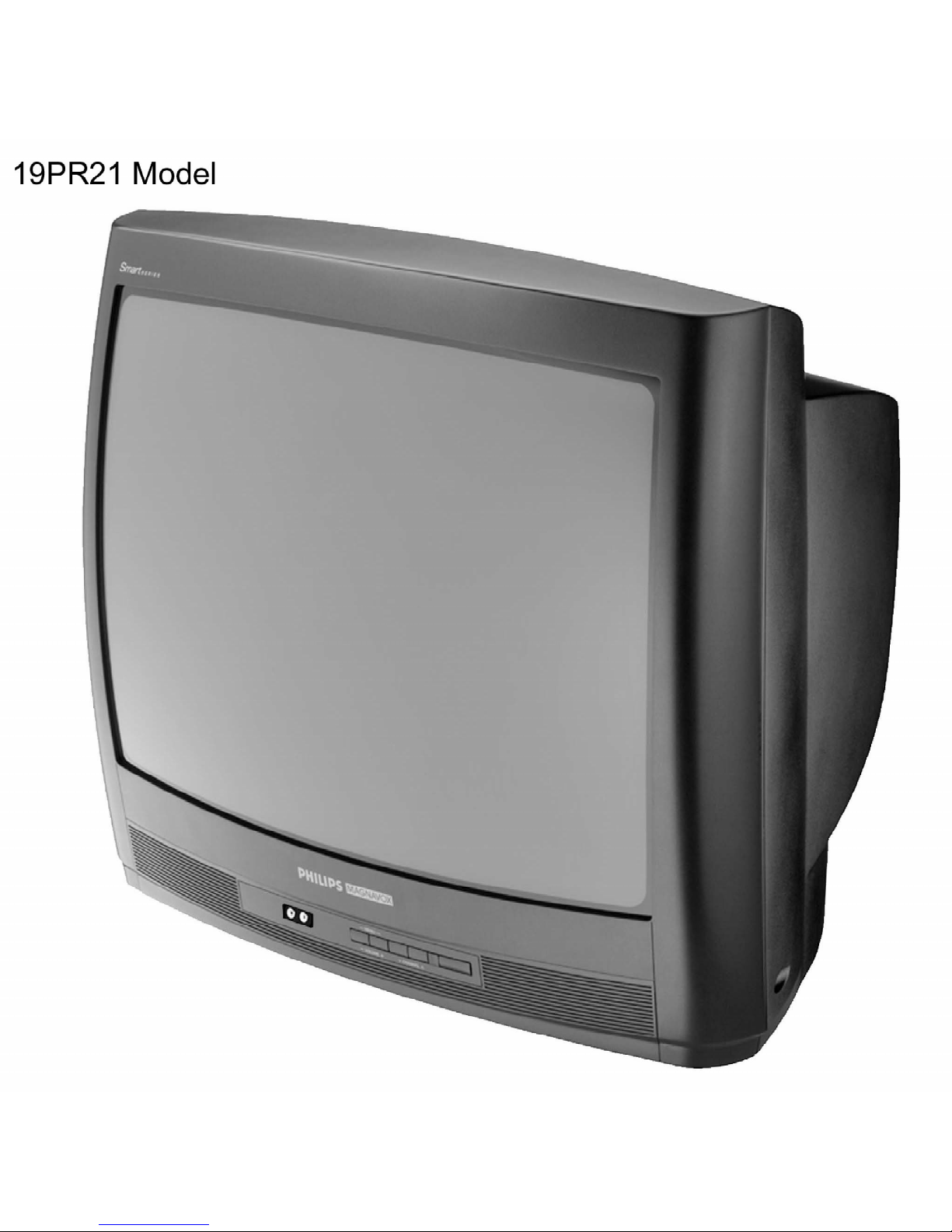
Display Product View - 19PR21
Model to Module List
The Model to Module list shown below identifies all electrical panels, modules and assemblies used in
each model produced with the J8 chassis. This information was current at time of printing.
Information concerning cabinet parts and cabinet mounted parts (CRT/Yoke/etc.) is shown in the Cabinet
Replacement Parts List.
If you are attempting to service a model equipped with the J8 chassis, the necessary electrical information
should be covered in this service manual, even if the corresponding model number is not listed.
PHILIPS/MAGNAVOX MODELS
Model Size
Panel Number Description
13PR20C1 13“
00EMJ800 Main Chassis
PR1306C1 13“
00EMJ801 Main Chassis
PR1320C1 13“
00EMJ800 Main Chassis
PR1392X1 13“
00EMJ802 Main Chassis
19PR21C1 19“
00EMJ803 Main Chassis
19PR21C2 19“
00EMJ803 Main Chassis
19PS57C1 19“
00EMJ805 Main Chassis
00ASD100 Sound Panel
PR1906C1 19“
00EMJ804 Main Chassis
PR1921C1 19“
00EMJ803 Main Chassis
PS1947C1 19“
00EMJ806 Main Chassis
00ASD100 Sound Panel
Model/Chassis Feature Chart
Display Feature Chart
Specifications
STANDBY CONDITIONS
Page 16

Power consumption: < 3 Watts
Volume: 64 steps.
PICTURE TUBES
Screen sizes & tubes: 13“/19“
Maximum average beam current:
13“: 0.75 mA
19“: 1 mA
EHT voltage
13“: 24.4 ± 1kV (no load)
19“: 26.8 ± 1kV (no load)
COLOR
Synchronisation
Sub-carrier pull-in range
NTSC systems: > ± 250 Hz
PICTURE PERFORMANCE
Chroma (3.579 MHz) suppression.: > 18 dB
PICTURE CONTROL :
Brightness
Color
Picture
Sharpness
Tint
Contrast Plus
SOUND POWER OUTPUTS:
Stereo: 2 x 1 Watts
Mono: 1 Watt
SPEAKERS:
Types: 3“ round
16 Ohm: 4W
8 Ohm: 2W
SOUND CONTROLS:
Mute: on/off
AVL: on/off
SOUND MUTE: When there is no video recognition on terrestrial tuner signal the sound will be muted.
POWER SUPPLY
SPECIFICATIONS/PERFORMANCE
Mains voltage range: 120 10 %
Mains frequency: 60 Hz
Chassis mains insulated: Yes
Power consumption in standby: < 3W
Power consumption normal mode:
13“: 48 W 10 % (IEC)
19“: 67 W 10 % (IEC)
Page 17
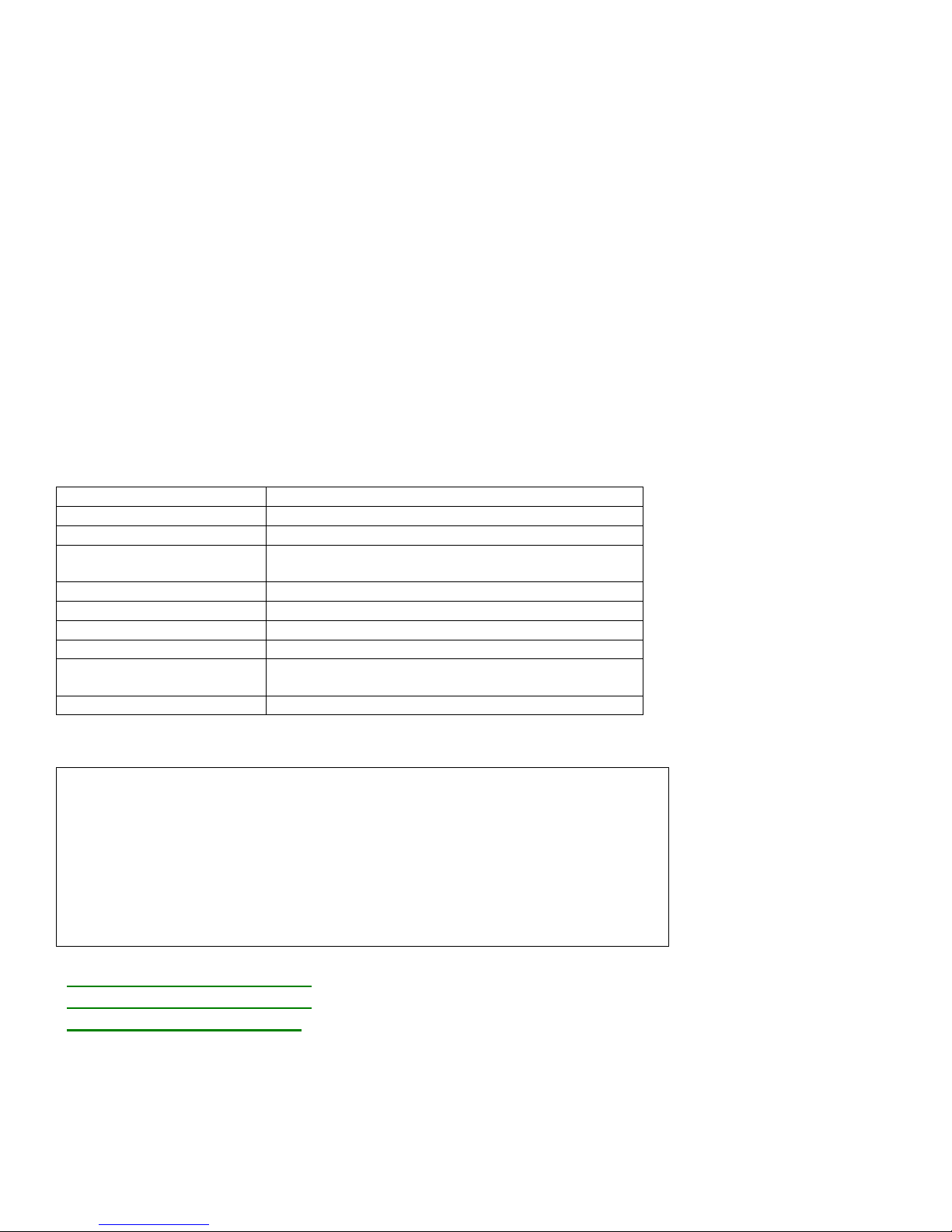
CLOSED CAPTION
V – CHIP FUNCTION AVAILABLE
Video-in (Cinch)
Close Caption
Only CC-1 and CC-2 decoding and display
No Text mode
No Extended Data Sevices (EDS)
Automatic CC-1 selection at user mute
LOCAL CONTROLS: Mainsswitch
5 local keys
EXTERNAL CONNECTIONS
FRONT
Headphone
Audio-in (Cinch)
REAR
Tuner
ESD-protected: 15 kV(Gnd) , 4kV(Signal)
HEADPHONE
Option Yes
Location Front
Peripherals Headphones with impe dance between 8 - 600
Features When headphone plug is con nec ted, loud speaker
sound is muted.
Volume control: loud speaker volume
Connector type 3.5 mm stereo Jack, with switch
Specifications Output: 8 < 4 mW
600 < 4 mW
Sound is the same as from
the loudspeakers.
ESD-protected 4 kV(Signal)
Remote Cross Reference
Model Part Number Description
13PR20C121 3139 228 83601 Remote Transmitter RC1112901/04
19PR21C121/C122/C125/C222 3139 228 83601 Remote Transmitter RC1112901/04
19PS57C121/C125 3139 228 83601 Remote Transmitter RC1112901/04
PR1306C121 3139 228 83591 Remote Transmitter RC1112501/04
PR1320C121 3139 228 83601 Remote Transmitter RC1112901/04
PR1392X121 3139 228 81461 Remote Transmitter RC282901/04W
PR1906C121/C122/C125 3139 228 83591 Remote Transmitter RC1112501/04
PR1921C121/C125 3139 228 83601 Remote Transmitter RC1112901/04
PS1947C121/C125 3139 228 83601 Remote Transmitter RC1112901/04
Display RC1112501 Remote
Display RC1112901 Remote
Display RC282901 Remote
Page 18

Jack Panel Information
Display Jack Panel Information Chart
Glossary of Terms and Abbreviations
2CS Two Channel Stereo
AFC Automatic Frequency Control
AFT Automatic Fine Tuning
AP Asia Pacific
ATS Automatic Tuning System
AV External Audio/Video
AVL Automatic Volume Level control
BTSC Broadcast Television Standard Committee (TV stereo)
CBA Circuit Board Assembly (PCB)
CC Closed Captioning
CSM Customer Service Mode
CVBS Color Video Blanking Sync
DNR Dynamic Noise Reduction
EEPROM Electrical Erasable Programmable Read-Only Memory
EIA Electronics Industry Association
Error Buffer Register that keeps track of errors that occur and stores error codes
Error Code A numerical value used to indicate a failure in the television
EU Europe
EXT External audio/video input
FM Frequency Modulation
I.F. Intermediate Frequency
I²C Inter IC bus, 2-wire bi-directional (SCL/SDA)
ID Identification
IDENT Horizontal coincidence signal, transmitter identification
IF Intermediate Frequency
IN ITT sound IC with NICAM function
IT ITT sound IC without NICAM function
LATAM Latin America
LED Light Emitting Diode
Local Keyboard The buttons (usually volume up, volume down, channel up, and channel down)
located on the front of the television set
MA Mono All; single mono carrier receiver
NICAM Near Instantaneous Companding Audio Multiplex; Digital Sound System
NR Noise Reduction
NTSC National Television Systems Committee (video)
NVM Non Volatile Memory
OB Option Byte (Feature Byte)
OSD On Screen Display
PCB Printed Circuit Board (CBA)
PIP Picture In Picture
PLL Phase Locked Loop
PP Personal Preference
RAM Random Access Memory
RC Remote Control
RC-5 Remote Control System 5
RGB Red Green Blue
ROM Read Only Memory
Page 19

SAP Second Audio Program
SCL Serial Clock
SDA Serial Data
SDAM Service Default Alignment Mode
SVHS Super Video Home System
THD Total Harmonic Distortion
Top Level Menu This refers to the main menu (as opposed to sub menus) in SAM
V-Chip Violence-Chip
VCR Video Cassette Recorder
Y/C Luminance/Chrominance (video)
Safety Instructions - Resolder Notice
1
Safety regulations require that during a repair:
• the set should be connected to the mains via an isolating transformer
• safety components, indicated by the symbol:
should be replaced by components identical to the original ones
• when replacing the CRT, safety goggles must be worn
2
Safety regulations require that after a repair the set must be returned in its original condition. In
particular, attention should be paid to the following points:
Note:
This resoldering is advised to prevent bad connections due to metal fatigue in solder joints, and
is therefore only necessary for television sets older than 2 years.
• As a strict precaution, we advise you to resolder the solder joints through which the horizontal
deflection current is flowing, in particular:
- All pins of the line output transformer (LOT)
- flyback capacitor(s)
- S-correction capacitor(s)
- line output transistor
- pins of the connector with wires to the deflection coil
- other components through which the deflection current flows
• Resolder points are marked by a white circle on the bottom of the CBA.
• The wire trees and EHT cable should be routed correctly and fixed with the mounted cable
clamps.
• The insulation of the mains lead should be checked for external damage.
• The mains lead strain relief should be checked for its function in order to avoid touching the
CRT, hot components or heat sinks.
• The electrical DC resistance between the mains plug and the secondary side should be checked
(only for sets which have a mains isolated power supply).
This check can be done as follows:
- unplug the mains cord and connect a wire between the two pins of the mains plug
- set the mains switch to the on position (keep the mains cord unplugged!)
- measure the resistance value between the pins of the mains plug and the metal shielding of
the tuner or the aerial connection on the set. The reading should be between 4.5 Megohm and
12 Megohm.
- switch off the TV and remove the wire between the two pins of the mains plug
• The cabinet should be checked for defects to avoid touching of any inner parts by the customer.
AC Cord Lead Dress
Page 20

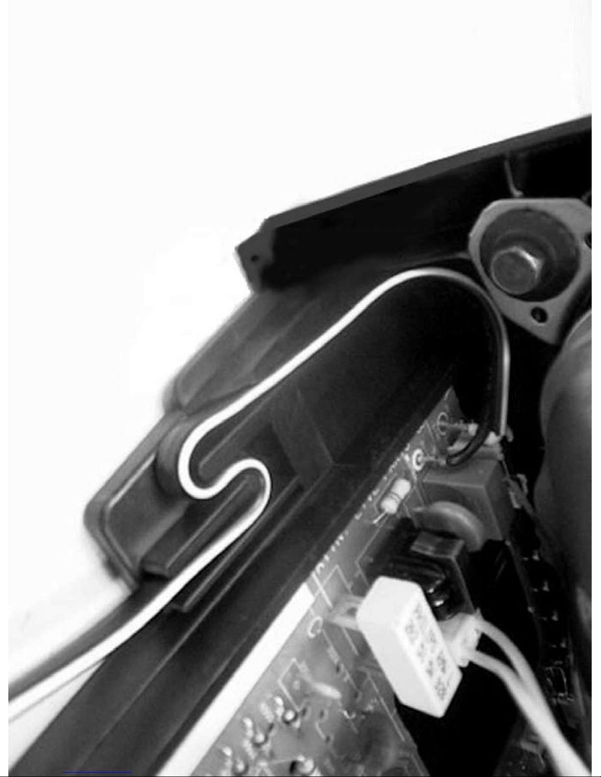
Note: After servicing this unit, be sure to check that the AC cord is properly dressed as shown in
the detailed view.
Display AC Cord Lead Dress
Page 21
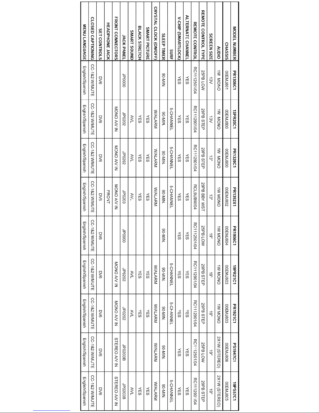
Display Feature Chart
Page 22
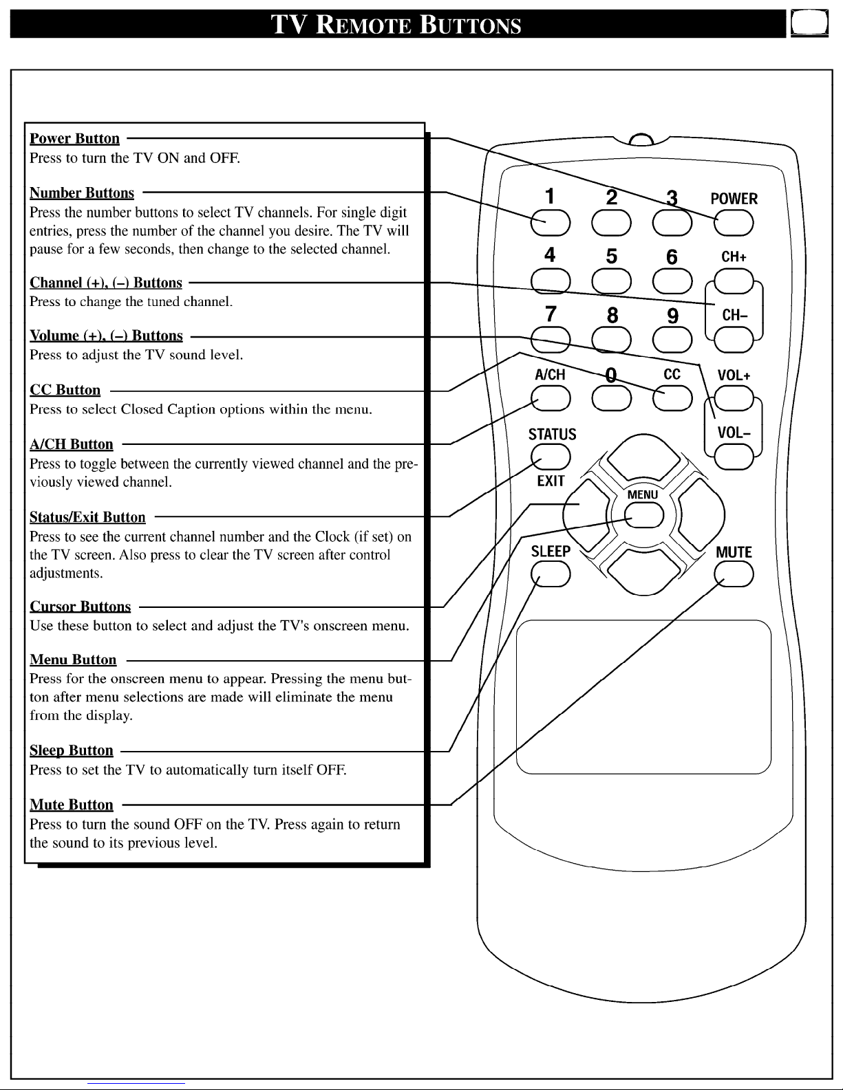
Display RC1112501 Remote
Page 23
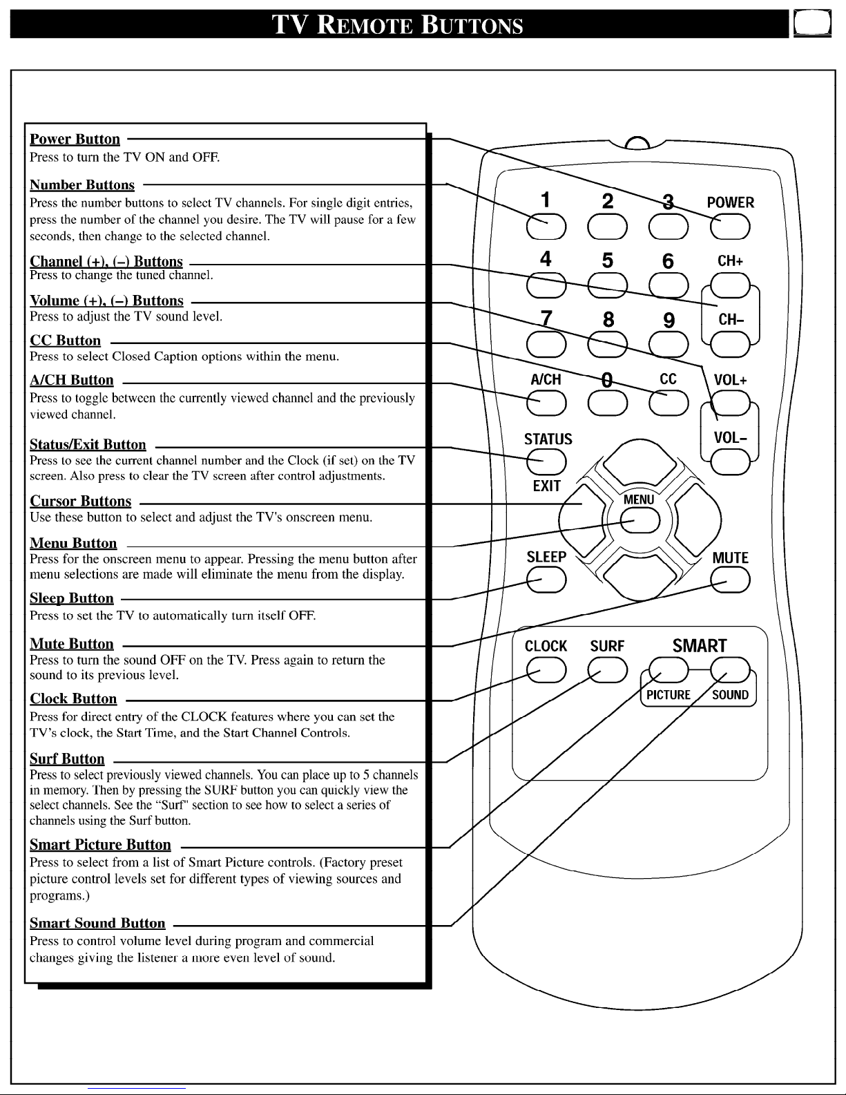
Display RC1112901 Remote
Page 24
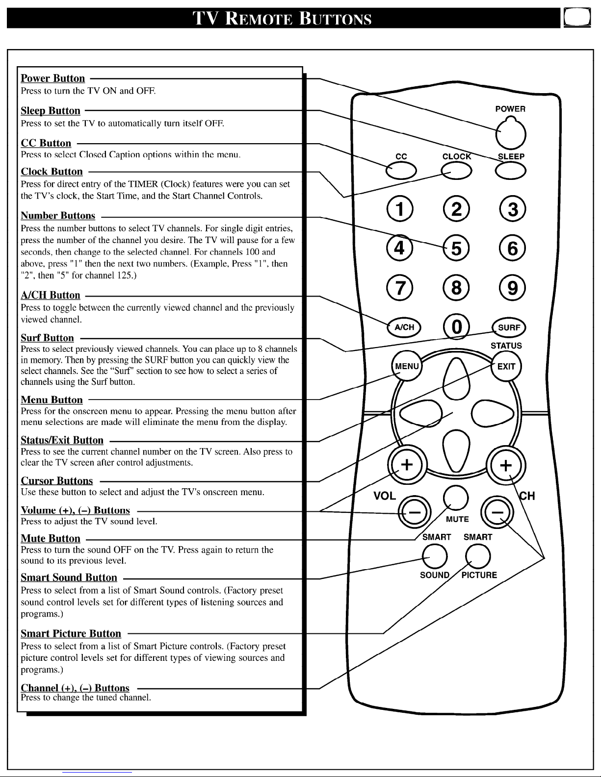
Display RC282901 Remote
Page 25
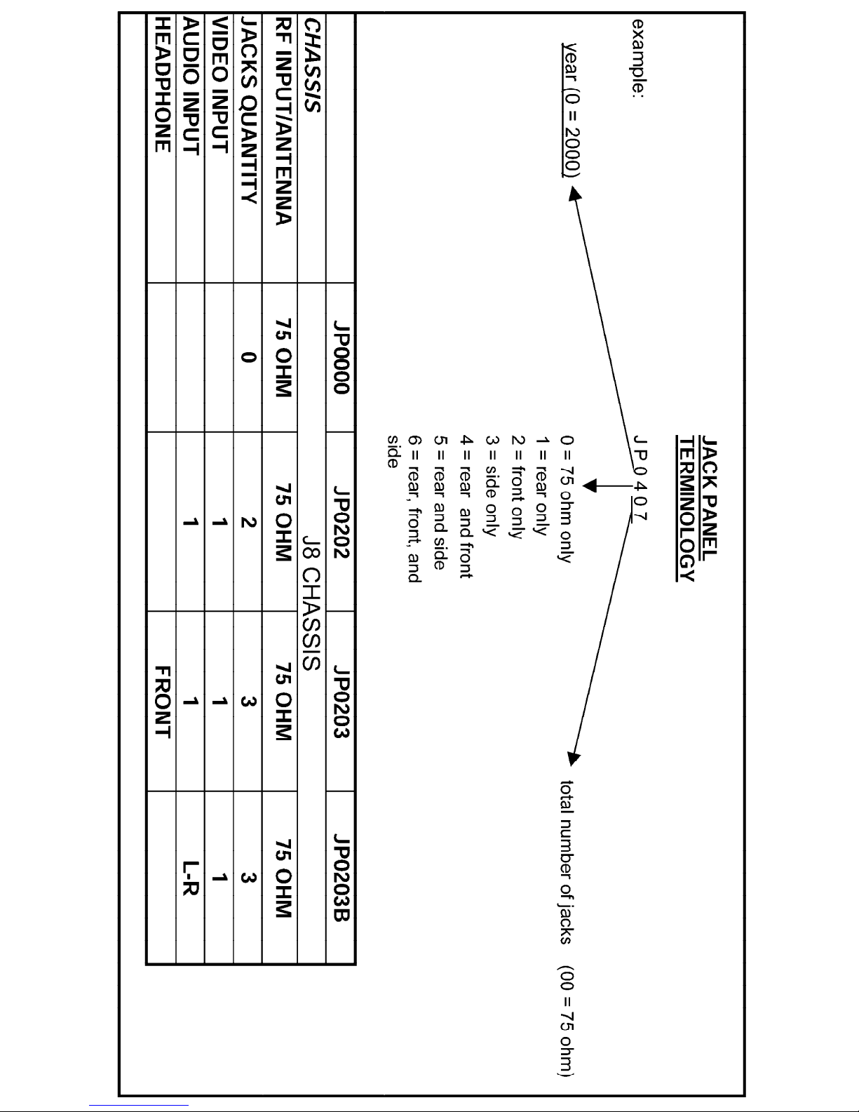
Display Jack Panel Information Chart
Page 26
Page 27
Page 28

Philips Consumer Electronics
Technical Service Data
Service and Quality
Service Publications Dept.
One Philips Drive
P.O. Box 14810
Knoxville, TN 37914
Manual 7590
Model no.: PR1906C121
First Publish: 10-09-01
Rev. Date: 04-04-00
Print Date: 18/07/2006
Electrical Adjustments
REFER TO SAFETY GUIDELINES
SAFETY NOTICE: ANY PERSON ATTEMPTING TO SERVICE THIS CHASSIS MUST FAMILIARIZE
HIMSELF WITH THE CHASSIS AND BE AWARE OF THE NECESSARY SAFETY PRECAUTIONS
TO BE USED WHEN SERVICING ELECTRONIC EQUIPMENT CONTAINING HIGH VOLTAGES.
CAUTION: USE A SEPARATE ISOLATION TRANSFORMER FOR THIS UNIT WHEN SERVICING
© Philips Electronics North America Corporation Visit our World Wide Web Site at http://www.forceonline.com
Page 29

J8 CHASSIS SERVICE ADJUSTMENTS
Service Adjustment Notes:
REQUIRED TOOLS FOR SERVICING
Isolation Transformer
Multimeter
Oscilloscope
High Voltage (100:1) Oscilloscope Probe
Sencore VG91 Universal Video Generator
Caution: The J8 chassis incorporates a "hot" ground system. Always use a separate isolation
transformer when applying power to the exposed chassis.
Unless Otherwise Specified:
1. All service adjustments are "hot" voltagewise. For maximum safety, ensure the use of properly
insulated tools.
2. Refer to the J8 Main Chassis Printed Circuit Board for location of test points and adjustable
components.
3. Grid Locations (Ex.: D-3) next to the reference numbers for components refer to the Main Chassis
Printed Circuit Board.
Focus Adjustment
1. Tune the set to a local or cable station.
2. Adjust the Focus Control (located on the upper part of the flyback transformer) for best picture details
at high light conditions.
Degaussing the Television
1. Position the television so that the screen faces the direction it will be facing when in use.
2. Ensure the set is turned off.
3. Move a degaussing coil in a circular motion slowly around the sides and front of the set.
4. Continue this motion while withdrawing the degaussing coil at least six feet from the television, and
then disconnect the degaussing coil from its power source.
Service mode
Introduction
The service mode is a combined Service Default Mode (SDM) and Service Alignment Mode (SAM). This
service mode is Called SDAM. When the television is in SDAM, all normal features (such as volume
control and direct channel access) are available. In service mode there will be an "S" displayed (in green)
at the top right of the screen. All other Service OSD’s will also be in green.
Error buffer
Error codes will indicate failures in the television.
A unique error code is available for:
• activated protection
• failing I2C device
• general I2C error
• RAM failure (e.g. internal RAM of microprocessor)
Page 30

Other error codes are:
• Video Chip start-up failure
The last five errors, stored in the NVM, are shown in the service menu. This is called the error buffer.
An error code will be added to the buffer if it differs from the last error detected.
If errors occur simultaneously, and the codes for these errors differ from the errors currently on screen,
the display will be updated to reflect this change.
The error that is found last is displayed on the left. The error code to the right should be used to solve a
multiple error fault. If an intermittent fault occurs refer to the stored error code.
Example:
Suppose the display shows: 7 5 2 0 0
In this case, the last error detected was a Stereo I2C error.
A seven (7) appears at the 1st position (on the left), and pushes the previous error(s) detected one space
to the right.
The following error codes have been defined:
0 = No error
1 = Master Protect (Master Protect, Monitors Beam Current/Xray(6732), 8v LOT(6730), 25v
LOT(6731), vertical(6755), tuner 5v (6733), these diodes will pull pin 26 of micro 7600 low and
shut off TV.
A one (1) will be stored after the fault is cleared.)
2 = I2C error while communicating with a processor
3 = General I2C error (*)
4 = Internal RAM error micro controller
5 = I2C error EEPROM error
6 = I2C error PLL tuner
7 = Stereo I2C error
Note: I2C =(SCL/SDA)
(*) General I2C error means: no I2C device is responding to the particular I2C bus.
Possible causes:
SCL Short circuit to GND, SDA Short Circuit to GND, SCL Short Circuit to SDA, SDA Open Circuit
(at uP pin), SCL Open Circuit (at uP pin)
Cause and Effect
In case a failure identified by an error code automatically results in other error codes (cause and effect),
only the error code of the MAIN failure will be displayed. Example: In case of a failure of the I2C bus
(CAUSE), the error code for a „general I2C failure“ will be displayed. The error codes for the single
devices (EFFECT) won’t be displayed.
NVM replacement or Defective NVM
After replacing a NVM (or with a defective/no NVM) default settings will be used that enable the set to start
up and that allow access to the Service „SDAM“ Mode.
Service unfriendly modes
In the service modes, a number of modes/features are ignored since they interfere with diagnosing or
repairing a set. These are „service unfriendly modes.“
Page 31

„Ignoring“ means that the event that is triggered is not executed, the setting remains unchanged.
ways:
(Example: Timer OFF: 8:00 PM; the set will not switch OFF in service mode at 8.00PM, but the setting will
remain).
These modes are:
• Blue mute.
• Auto switch off (when there is no ident signal).
• Automatic user menu time-out (menu switches back/OFF automatically) except for Surf menu.
Service Mode (SDAM) entry and exit
1. Entering the Service Default Alignment Mode (SDAM) can be achieved in either of the following two
a. Press the following key sequence on the remote control transmitter while the set is in Standby mode:
0-6-2-5-9-6-Status (Do not let the sequence time-out between entries)
b. Short service pin 0239 (on the CBA) to ground and switch power-on.
2. To select an option menu item in SDAM, use the Menu Up or Menu Down buttons on the remote
control.
3. To enter into a sub-menu, press the Menu Right button on the remote control.
4. To change the value of an option code, use the Menu Left or Menu Right buttons.
5. Press the Status button on the remote control to toggle the OSD on and off to prevent the OSD from
interfering with measurements and oscilloscope waveforms.
6. Press the Menu button on the remote control while in SDAM to switch the software to a Virtual
Customer Mode; the letter "S" will still be displayed in the upper right corner of the screen. In this
mode, all customer menu adjustments to the set can be performed. From the Virtual Customer Mode,
press the Menu button to return to the SDAM display.
7. To exit the Service Default Alignment Mode and erase the error codes, turn the unit off with the Power
button on the remote control, then unplug the ac cord.
8. To exit the Service Default Alignment Mode and save the error codes, unplug the ac cord to turn off the
set. Turn the set back on, the Service Default Alignment Mode will still be active. At this point turn the
set off using the Power button on the remote control, then unplug the ac cord.
Display Figure 1 - SDAM Flow Chart
SDAM mode
Software identification, version and cluster
The software identification, version and cluster will be shown in the service main menu display.
These numbers consists of the last part of the customer identification printed on the IC package, the
screen will show `AAABBC-X.Y'.
− AAA is the engineering project name: L9S
− BB is a function specification indicating specific functionality or a region. Processors with the same
− C is the language cluster number within the „BB“ software version
− X is the main version number (when release for production „X“ will start at „1“)
− Y is the sub version number (when release for production „Y“ will start at „0“)
− the main version number is updated with a major change of specification and is incompatible with the
− the sub version number is updated with a minor change and is backward compatible with the previous
Display Figure 1 - SDAM Flow Chart
engineering project name and function name are interchangeable, except for the languages they
support.
previous software version.
versions.
Page 32
− if the main version number changes, the new version number is written in the EEPROM.
− if the sub version number changes, the new version number is written in the EEPROM.
− Note: a new micro controller is considered to be compatible if it works instead of the old software and
the functionality is not significantly changed.
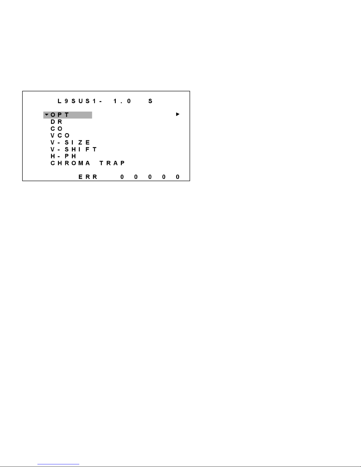
The following menu will be displayed whenever SDAM is entered. In this menu the error buffer can be
viewed, and the option byte(s) can be (re)programmed. The SDAM display is shown below:
Figure 2 - SDAM menu
Explanation:
AAABBC The software identification and cluster
AAA: Engineering project name.
L9S
BB: Function specification indicating region.
US (USA)
C: Language cluster number:
1 through 9, then A through Z (35 revisions possible)
X: Software, Main version number 1.0
Y: Software, Sub-version number 1.0
S The character "S" to indicate that the TV set is in service mode (SDAM).
The ERR (Error) row displays the last five errors detected; the most recent error will be displayed to the
left.
Geometry Adjustments
Notes:
1. The following Geometry adjustments were performed with a Sencore VG91 Universal Video Generator.
2. Set the VG91 Generator as follows: STD TV Ch. 3, RF-IF Range set to HI, RF-IF Level set to
NORMAL (1), Video Pattern = Raster, R-G-B raster controls OFF, crosshatch or center cross pattern
as required.
3. Connect the RF output of the generator to the Television Antenna Input, and adjust the VG91 level to
remove any snow from the raster.
Vertical Size (V-SIZE) adjustment:
1. Enter the Service Default Alignment Mode (SDAM) in either of the following two ways:
a. Press the following key sequence on the remote control transmitter while the set is in Standby
mode: 0-6-2-5-9-6-Status (Do not let the sequence time-out between entries)
b. Short service pin 0239 (on the CBA) to ground and switch power-on.
Page 33

2. From the SDAM menu, use the Menu Up/Down buttons to highlight V-SIZE.
3. Input a cross-hatch pattern to the antenna/cable input terminal.
4. Using the Menu Left button, reduce the value so that the picture does not fill the entire screen.(Range
of 0-63)
5. Input a center cross pattern to the antenna/cable input terminal.
6. Use the Menu Up/Down buttons to select V-SHIFT (Vertical Shift) from the SDAM menu and, using the
Menu Left/Right buttons, center the picture on the screen, top to bottom. (Take note of the fiduciary
marks at the right and left edges of the CRT)
7. Input a cross-hatch pattern to the antenna/cable input terminal.
8. Using the cursor up/down buttons, select V-SIZE (Vertical Size) from the SDAM menu, and use the
Menu Right button to increase the register value to obtain a slight overscan.9. If other Geometry adjustments are needed, proceed to the necessary adjustment using the Menu
Up/Down buttons.
Vertical Shift (V-SHIFT):
1. Enter the Service Default Alignment Mode (SDAM) in either of the following two ways:
a. Press the following key sequence on the remote control transmitter while the set is in Standby
mode: 0-6-2-5-9-6-Status (Do not let the sequence time-out between entries)
b. Short service pin 0239 (on the CBA) to ground and switch power-on.
2. From the SDAM menu, use the Menu Up/Down buttons to highlight V-SHIFT.
3. Input a center cross pattern to the antenna/cable input terminal.
4. Using the Menu Left/Right buttons, adjust V-SHIFT so that the horizontal bar is properly centered, top
to bottom. (Range of 0-7)
5. If other Geometry adjustments are needed, proceed to the necessary adjustment using the Menu
Up/Down buttons.
Horizontal Phase (H-PH):
Note: This adjustment centers the video on the raster. It does not move the raster.
1. Enter the Service Default Alignment Mode (SDAM) in either of the following two ways:
a. Press the following key sequence on the remote control transmitter while the set is in Standby
mode: 0-6-2-5-9-6-Status (Do not let the sequence time-out between entries)
b. Short service pin 0239 (on the CBA) to ground and switch power-on.
2. From the SDAM menu, use the Menu Up/Down buttons to highlight H-PH.
3. Input a center cross pattern to the antenna/cable input terminal.
4. Using the Menu Left/Right buttons, adjust H-PH so that the vertical bar is properly centered, left to
right. (Range of 0-31)
5. If other Geometry adjustments are needed, proceed to the necessary adjustment using the Menu
Up/Down buttons.
Chroma Trap:
1. Enter the Service Default Alignment Mode (SDAM) in either of the following two ways:
a. Press the following key sequence on the remote control transmitter while the set is in Standby
mode: 0-6-2-5-9-6-Status (Do not let the sequence time-out between entries)
b. Short service pin 0239 (on the CBA) to ground and switch power-on.
2. Connect the oscilloscope to any one of the following points:
Base of 7320 on the CRT CBA.
Base of 7310 on the CRT CBA.
Base of 7300 on the CRT CBA.
3. From the SDAM menu, use the Menu Up/Down buttons to highlight CHROMA TRAP.
4. Using the Menu Left/Right buttons, select 0,1,2,3 CHROMA TRAP for minimum color burst.
Note: Try to adjust for minimum color burst at all three points. One register value probably will
not provide the point of minimum color burst at all three points; therefore find the register
value which provides the best possible balance between the three points.
Page 34
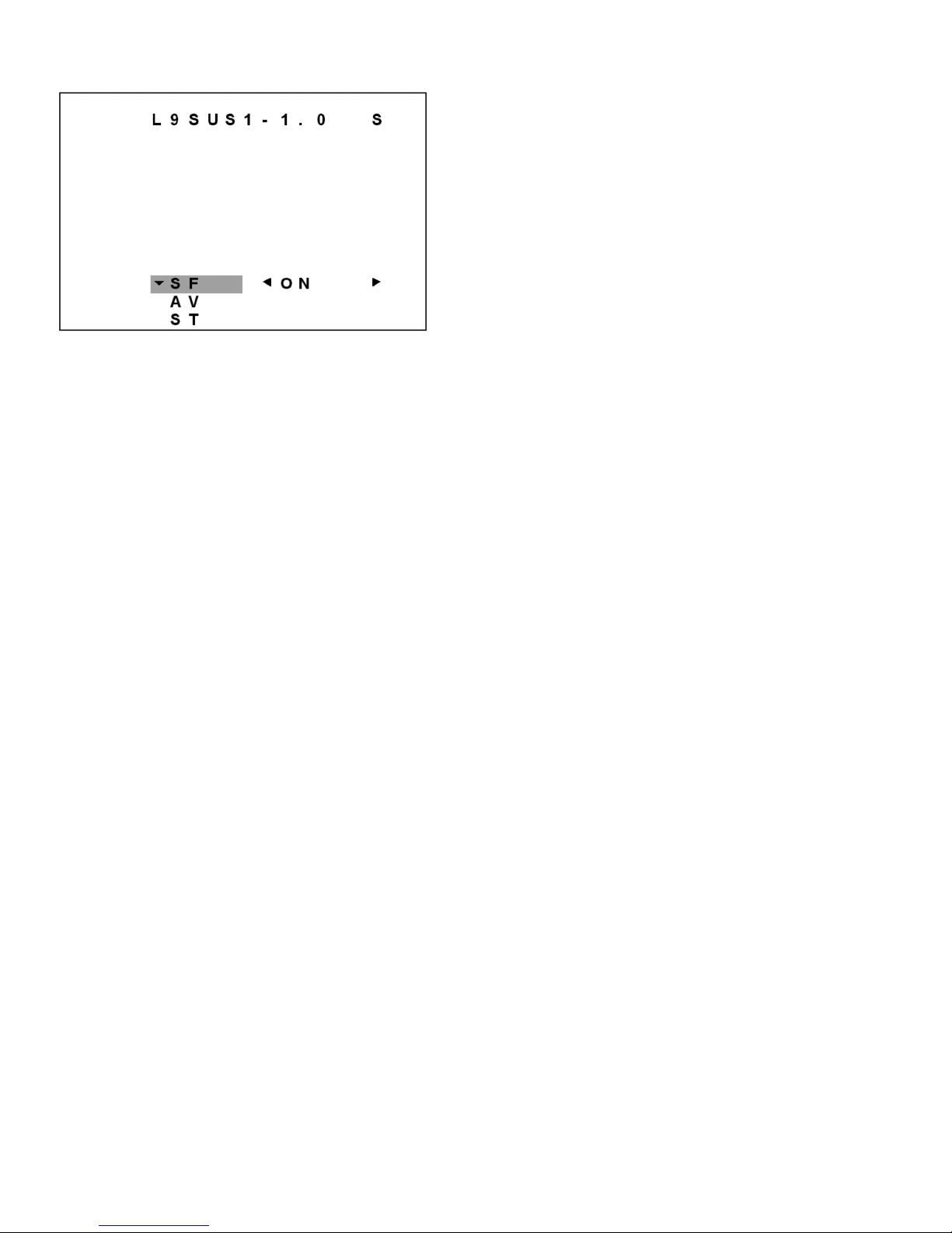
Figure 3 - OPT sub-menu
The OPT (Options) sub-menu is entered using the MENU LEFT/RIGHT command. This sub-menu
displays the option items available which can be selected by using the MENU UP/DOWN buttons on the
remote and the option item values can be changed using the MENU LEFT or RIGHT buttons on the
remote.
Smart Features (SF)
When the SF function is off the Smart Features are disabled.
When the SF function is on the Smart Features are enabled.
(Smart Features consists of : Smart Sound, Smart Picture, Surf and Clock) functions
External Audio Video (AV)
When the AV function is off the external Audio Video is disabled.
When the AV function is on the external Audio Video is enabled.
Stereo (ST) (only for Stereo sets)
When the ST function is off the stereo is disabled.
When the ST function is on the stereo is enabled.
Tuner Adjustment:
AGC Takeover Point (AGC):
1. Enter the Service Default Alignment Mode (SDAM) in either of the following two ways:
a. Press the following key sequence on the remote control transmitter while the set is in Standby
mode: 0-6-2-5-9-6-Status (Do not let the sequence time-out between entries)
b. Short service pin 0239 (on the CBA) to ground and switch power-on.
2. Use the Menu Down button to highlight the VCO menu.
3. Use the Menu Right button to enter the VCO sub menu.
4. In the VCO sub menu, use the Menu Up/Down buttons to highlight RF-AGC.
5. Record the RF-AGC value currently in the register. (Range 0-127)
6. Use the Menu Right button to raise the value of AGC until snow appears in the picture.
7. Then use the Menu Left/Right buttons to reduce the AGC value until the snow disappears.
Caution: Single digit AGC values may cause overload.
Upon completion of Tuner adjustment, press the Menu button to return to the SDAM menu.
Figure 4 - VCO Sub-Menu
Page 35
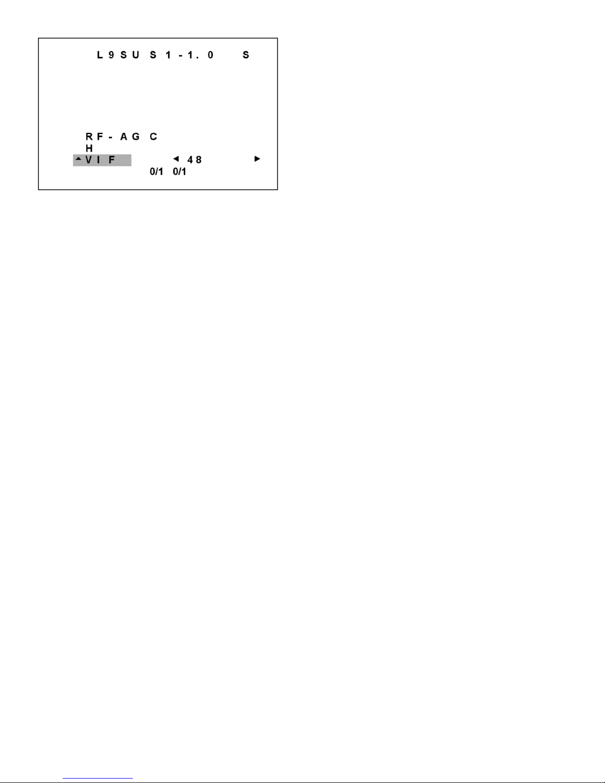
The VCO sub-menu consists of RF-AGC, H, and VIF items. RF-AGC (refers to RF AGC adjust; range of
0-127), H (refers to H VCO ADJ; range 0-7), and VIF (refers to VIF VCO adjust; range 0-63) items. Note
that when the VIF item value is being adjusted, the items AFT 0 (displays either 1/0) and AFT 1 (displays
either 1/0) are displayed permanently. AFT0 and AFT1 are not user controllable, they are used to indicate
correct alignment value settings for VIF. When the VIF sub-menu item is highlighted AFT 0 and AFT 1 are
indicated below the register value.
VCO Adjustments:
1. Tune the set to an active channel.
2. Enter the Service Default Alignment Mode (SDAM) in either of the following two ways:
a. Press the following key sequence on the remote control transmitter while the set is in Standby
mode: 0-6-2-5-9-6-Status (Do not let the sequence time-out between entries)
b. Short service pin 0239 (on the CBA) to ground and switch power-on.
3. From SDAM Menu, use the Menu Up/Down buttons to highlight VCO.
4. Use the Menu Right button to enter the VCO sub menu.
5. Use the Menu Up/Down buttons to highlight VIF.
6. Adjust the value of the VIF sub menu item so that AFT0 and AFT1 indicate 0 after the set is warmed
up.
7. After the values are set, or if no changes are required, press Menu to return to the SDAM menu.
Master Screen (VG2) White Balance Setup:
1. Apply a center cross pattern to the antenna cable input terminal.
2. Enter the Service Default Alignment Mode (SDAM) in either of the following two ways:
a. Press the following key sequence on the remote control transmitter while the set is in
Standby mode: 0-6-2-5-9-6-Status (Do not let the sequence time-out between entries)
b. Short service pin 0239 (on the CBA) to ground and switch power-on.
3. Use the Menu Down button on the remote transmitter to highlight DR (Color Drivers).
4. Use the Menu Right button on the remote transmitter to enter the DR sub menu.
5. Record the DR values cuttently stored in each of the registers.
NOTE: Drive values range from 0-127. Factory preset for the colore driversis 63.
6. Set Red and Blue Drive Controls to mid-range (63). Green Drive is fixed at mid-range.
7. Press the Menu button to re4turn to the SDAM menu.
8. Use the Menu Up/Down on the buttons remote transmitter to highlight CO (Color Cutoff).
9. Use the Menu Left/Right buttons on the remote transmitter to set the Cutoff controls to 200.
10. Record the CO values currently stored in each of the registers.
NOTE: Cut off values range from 0-255. Factory preset values for the Cut off register is 200.
11 Press Menu to return to the main SDAM menu and power off to save.
12. With the OFF, set VG2 to minimum by rotating VG2 counterclockwise (located on the lower part of the
flyback transformer).
Page 36
13. Turn the set back off.
14. Adjust G2 (Screen) clockwise until a line just becomes visible. This line will be the color of the
dominant gun.
15. Adjust the other two cutoff controls to achieve a low level white line.
16. Apply a NTSC color bar signal with Chroma turnedoff. Tr-enter SDAM (see #2) and select the needed
sub menu as follows:
17. Make slight adjustments, if necessary, to the Red and Blue Drive controls to make the brightest bar
white.
18. Adjust the CO as needed, to touch up low light areas to make the darkest bar grey.
NOTE: The Color Drivers set the highlights and the Cut offs set the lowlights.
Also, these items interact. A Decrease of the Red Drive may require an increase of teh Red
Cut off, etc.
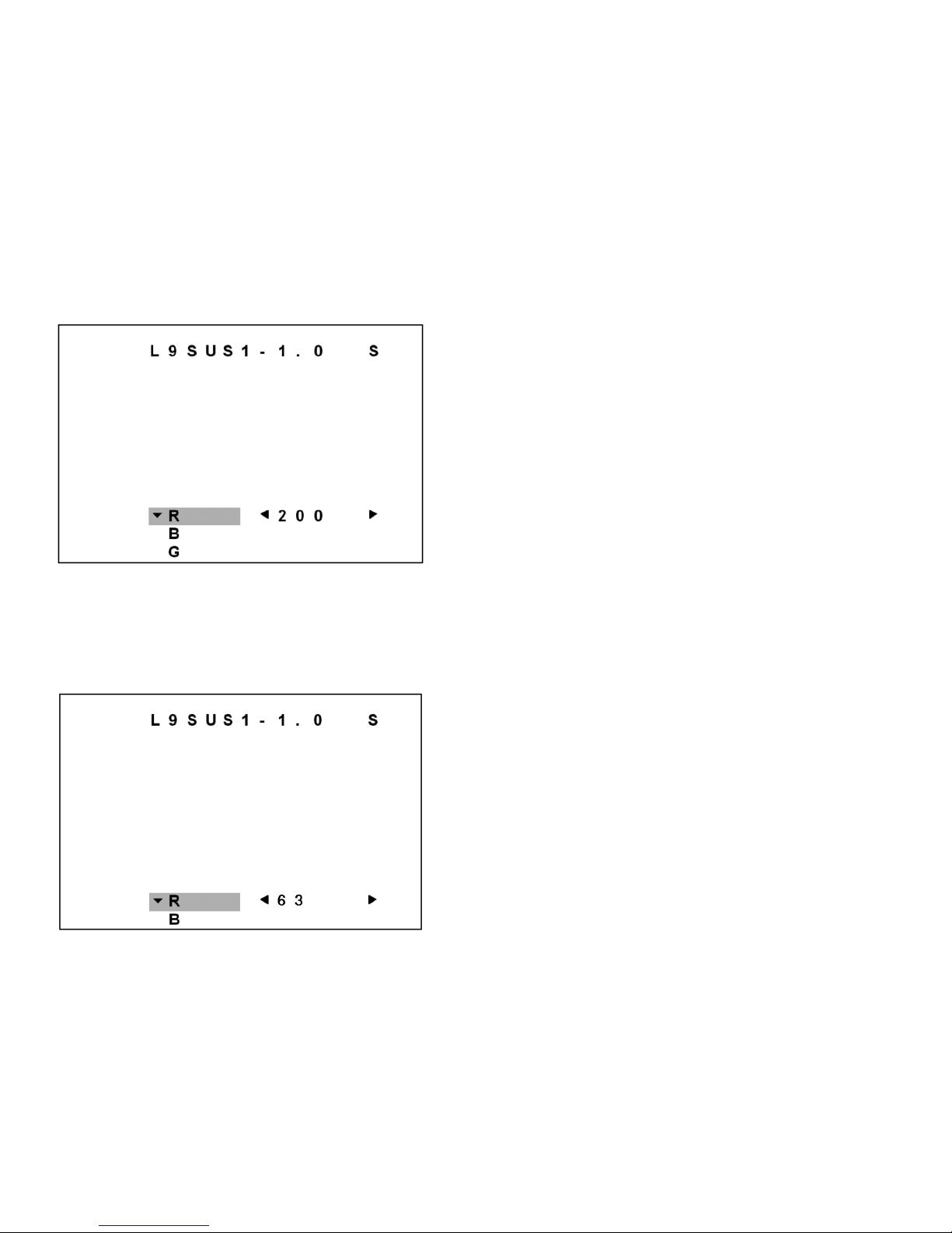
Figure 5 - Color Cutoff Sub-Menu
The CO (Color Cutoff) sub-menu consists of Red (R), Blue (B) and Green (G) cutoff values range from 0
to 255.
Figure 6 - Color Driver Sub-Menu
The DR (Color Drivers) sub-menu consists of Red (R), Blue (B) drive values range from 0 to 127. Factory
preset for the color drivers is 63.
Note: There is no Green color Drive register.
Page 37

Convergence and Purity Adjustments
Notes:
1. The following adjustments were performed with a Sencore VG91 Universal Video Generator.
2. Set the VG91 Generator as follows: STD TV Ch. 3, RF-IF Range set to HI, RF-IF Level set to NORMAL
(1), Video Pattern = Raster, R-G-B raster controls OFF, Mode Switch set to L+R, Audio Frequency set
to 300Hz, and 0 Pilot (max. CCW).
3. Connect the RF output of the generator to the Television Antenna Input, and adjust the VG91 level to
remove any snow from the raster.
Pre-Convergence Procedure
Note: The degaussing procedure should be performed prior to this adjustment.
1. Place the multi-pole Purity and Convergence Assembly with the 2-Y pole purity rings directly in the
gap between the G2 and G3 (focus) grids as
2. Enter the Service Default Alignment Mode (SDAM) in either of the following two ways:
a. Press the following key sequence on the remote control transmitter while the set is in Standby
mode: 0-6-2-5-9-6-Status (Do not let the sequence time-out between entries)
b. Short service pin 0239 (on the CBA) to ground and switch power-on.
3. Apply a center cross or crosshatch pattern to the antenna/cable input terminal.
4. From the SDAM menu, use the Menu Up/Down buttons to highlight CO (Color Cut-off).
5. Use the Menu Right button to enter the CO sub menu.
6. Using the Menu Up/Down buttons select G (green).
7. Using the Menu Left button set green to minimum.
8. Loosen the yoke clamp screw, pull the yoke back, and remove the three yoke wedges.
9. Slide the yoke all the way forward so that it rests against the bell of the CRT.
10. Tighten the yoke clamp screw so that the yoke does not drop away from the bell of the CRT.
11. Slowly spread, and if necessary, rotate the 2-Y pole purity rings so that the red and blue lines are at
least parallel and preferably coincide at the 6:00 and 12:00 positions
12. Proceed to the Color Purity Adjustment.
shown in Figure 7.
(refer to Figure 8).
Figure 7 - Convergence and Purity Assembly
Page 38
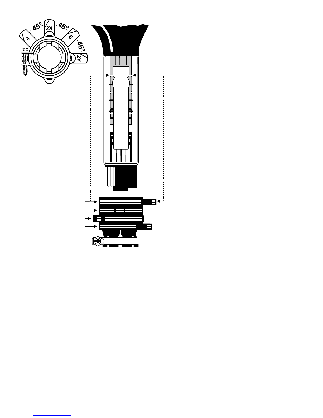
2Y POLE
2X POLE
4 POLE
6 POLE
ZERO
CORRECTION
POSITION
CONVERGENCE & PURITY ASSEMBLY
GAP
GRIDS
Figure 8 - 2X/2Y Spread/Rotate
(G2 & G3)
Page 39
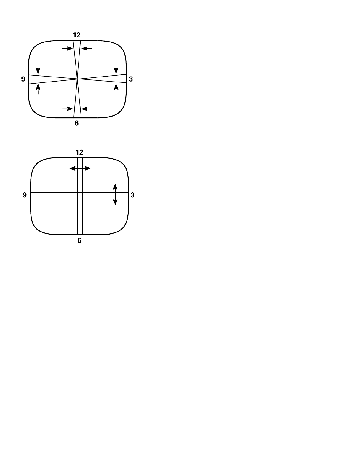
2X
ROTATE
2Y ROTATE
2X
SPREAD
2Y SPREAD
Color Purity Adjustment
1. Enter the Service Default Alignment Mode (SDAM) in either of the following two ways:
a. Press the following key sequence on the remote control transmitter while the set is in Standby
mode: 0-6-2-5-9-6-Status (Do not let the sequence time-out between entries)
b. Short service pin 0239 (on the CBA) to ground and switch power-on.
2. Connect a solid white pattern signal to the antenna/cable input terminal.
3. Use the Menu Up/Down buttons to highlight CO (The DR menu can also be used)4. Use the Menu Right button to enter the CO sub menu.
5. Use the Menu Up/Down buttons to select Blue, and use the Menu Left button to set Blue to minimum.
6. Use the Menu Up/Down buttons to select Red, and use the Menu Right button to set Red to maximum.
7. Slowly spread the 2-X pole purity rings to center the red portion of the screen, leaving the same
amount of green on one side of the screen as blue on the other side.
8. Tighten the yoke clamp screw slightly so that the yoke may be moved with some friction.
9. Proceed to the Static Center Convergence Adjustment.
Static Center Convergence Adjustment
1. Apply a center cross or crosshatch pattern to the antenna/cable input terminal and observe the screen
to ensure that the yoke is not tilted. If necessary, rotate the yoke to obtain a level raster.
2. Use the Menu Up/Down buttons to highlight CO (Cut-Off), and use the Menu Right button to enter the
CO sub menu.
3. Use the Menu Right button to set blue to maximum.
Page 40

4. Slowly spread, and if necessary, rotate the 4-pole magnetic rings to converge red and blue lines at the
center of the screen.
5. Use the Menu Up/Down buttons to select G (Green), and use the Menu Right button to set Green to
maximum.
6. Slowly spread, and if necessary, rotate the 6-pole magnetic rings to converge red/blue on green lines
at the center of the screen.
7. Repeat steps three and five for optimum performance.
8. Proceed to the Dynamic Edge Convergence Adjustment.
Dynamic Edge Convergence Adjustment
Note: To secure the correct position of the deflection yoke, three rubber wedges are used. They are
ultimately to be placed as shown in
1. Apply a crosshatch pattern to the antenna/cable input terminal.
2. Use the Menu Up/Down buttons to select G (Green), and use the Menu Left button to set Green to
minimum.
3. Tilt the yoke up and down to converge the red and blue vertical lines at the 6:00 and 12:00 positions
and the red and blue horizontal lines at the 3:00 and 9:00 positions
correct position has been found, place a rubber wedge between the yoke and the CRT. If the yoke is
tilted up, place wedge one as shown in Figure 9a; if it is tilted down, place wedge one as shown in
Figure 10a.
4. Tilt the yoke to the left and right to find the point of best possible convergence of the red and blue lines
at the edges, top and bottom of the screen as
located, place wedges two and three as shown in Figure 9b or Figure 10b.
5. Remove wedge one and place it in the final position as shown in
6. Use the Menu Up/Down buttons to select Green, and use the Menu Right button to set Green to
maximum.
7. Proceed to the White Balance Setup.
Figure 9c or Figure 10c.
shown in Figure 12.
(refer to Figure 11).
When the correct position is
When the
Figure 9c or Figure 10c.
Figures 9 & 10 - Wedge Placement
Page 41
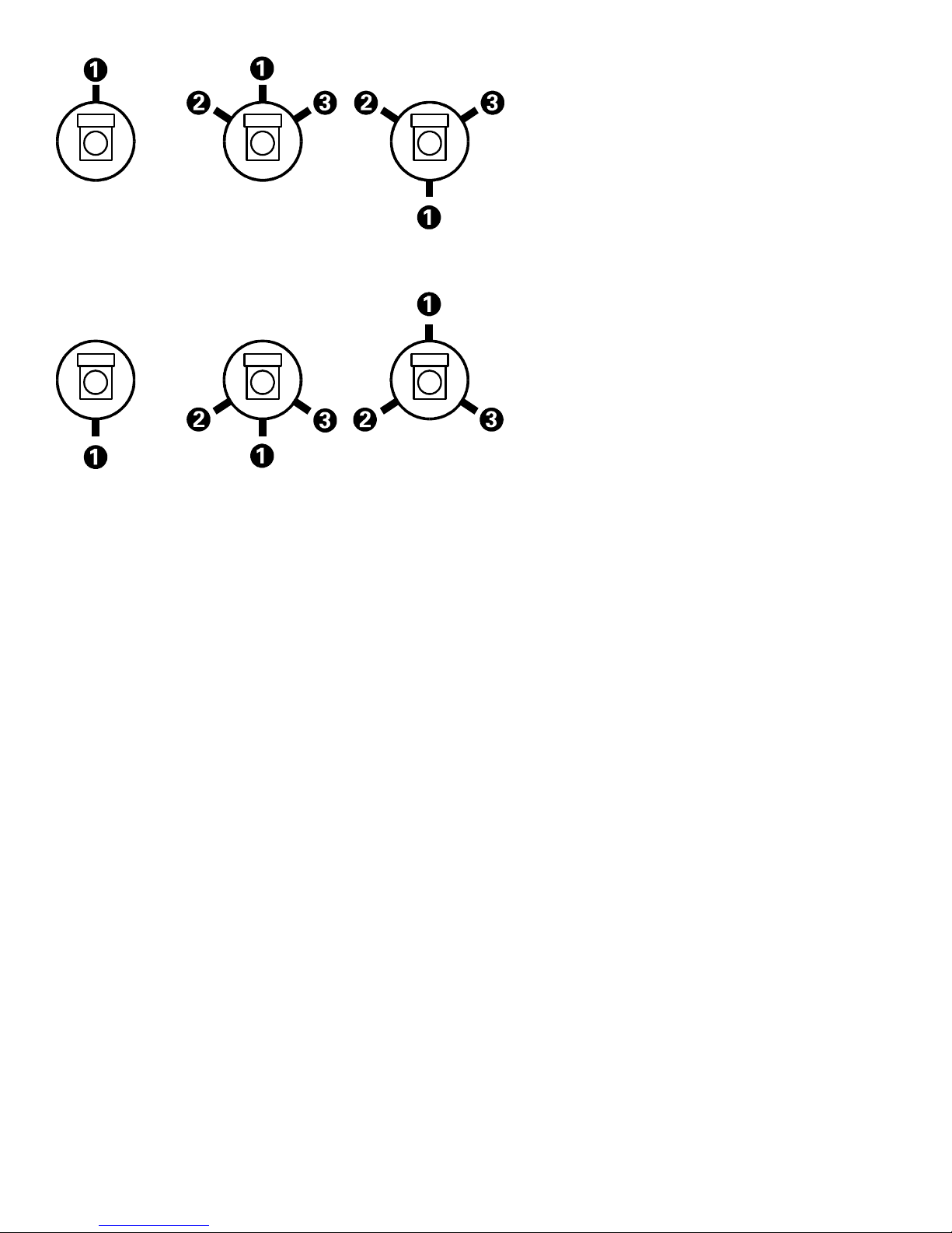
Fig. 9a Fig. 9b Fig. 9c
Fig. 10a Fig. 10b Fig. 10c
Figures 11 & 12 - Yoke Tilt
Page 42
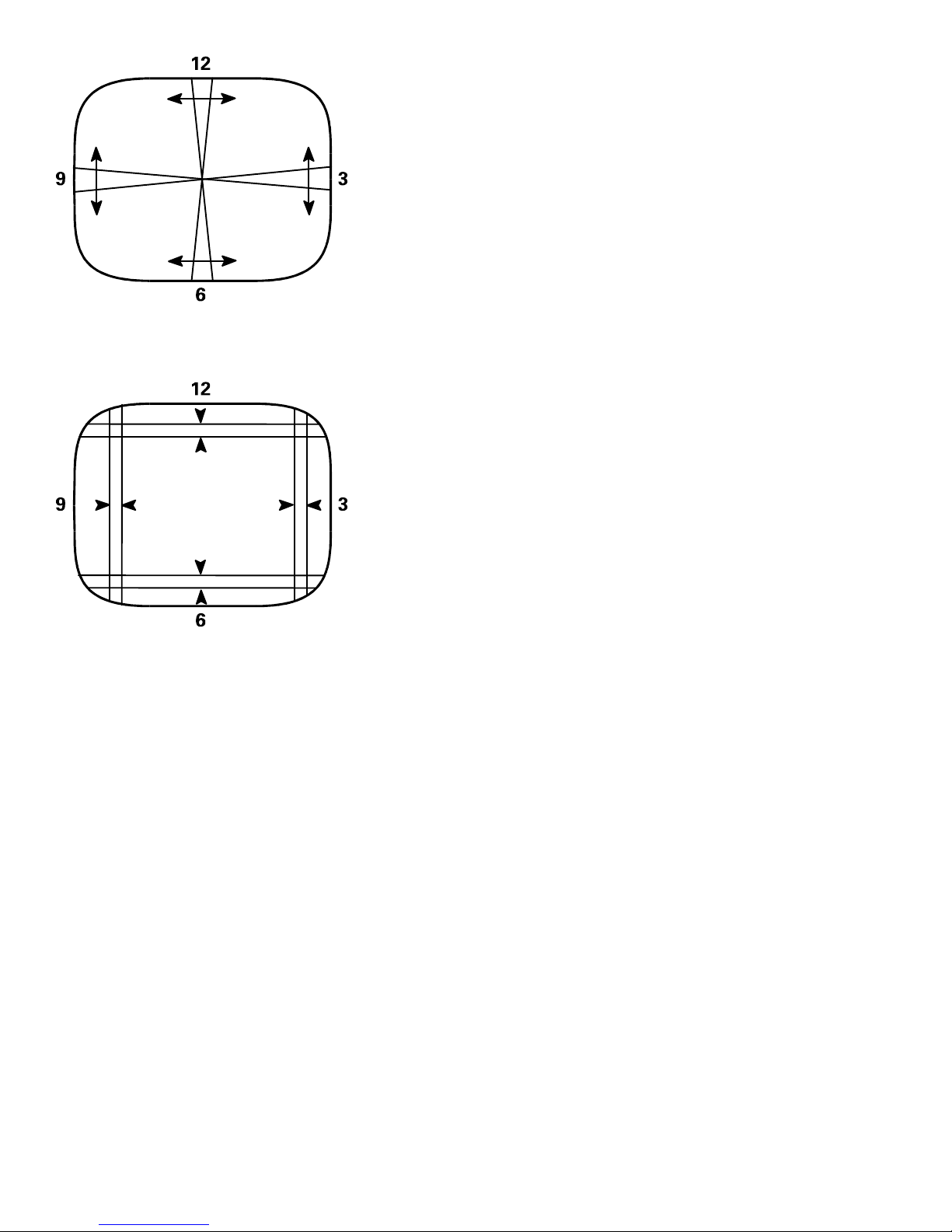
Figure 11
Figure 12
Page 43
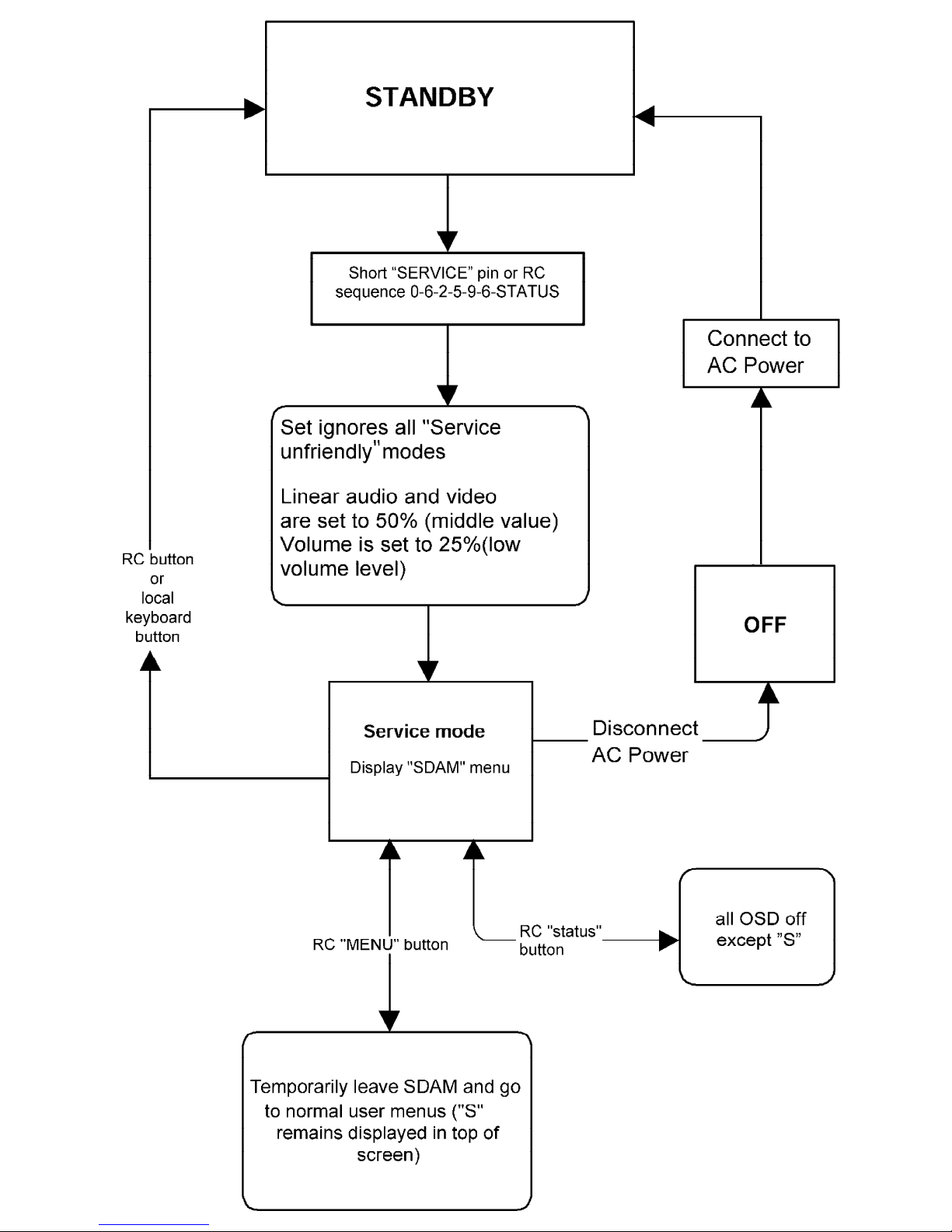
Display Figure 1 - SDAM Flow Chart
Page 44

Philips Consumer Electronics
Technical Service Data
Service and Quality
Service Publications Dept.
One Philips Drive
P.O. Box 14810
Knoxville, TN 37914
Manual 7590
Model no.: PR1906C121
First Publish: 10-09-01
Rev. Date: 04-04-00
Print Date: 18/07/2006
Training Information
REFER TO SAFETY GUIDELINES
SAFETY NOTICE: ANY PERSON ATTEMPTING TO SERVICE THIS CHASSIS MUST FAMILIARIZE
HIMSELF WITH THE CHASSIS AND BE AWARE OF THE NECESSARY SAFETY PRECAUTIONS
TO BE USED WHEN SERVICING ELECTRONIC EQUIPMENT CONTAINING HIGH VOLTAGES.
CAUTION: USE A SEPARATE ISOLATION TRANSFORMER FOR THIS UNIT WHEN SERVICING
© Philips Electronics North America Corporation Visit our World Wide Web Site at http://www.forceonline.com
Page 45
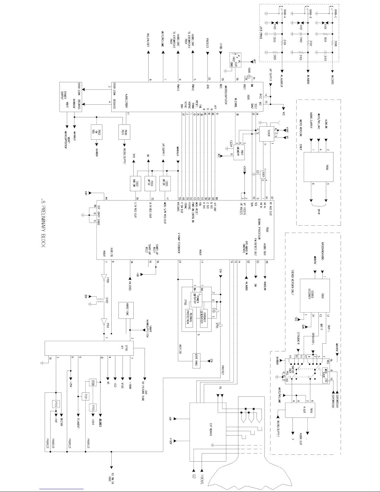
Page 46

Philips Consumer Electronics
Technical Service Data
Service and Quality
Service Publications Dept.
One Philips Drive
P.O. Box 14810
Knoxville, TN 37914
Manual 7590
Model no.: PR1906C121
First Publish: 10-09-01
Rev. Date: 04-04-00
Print Date: 18/07/2006
Parts List
REFER TO SAFETY GUIDELINES
SAFETY NOTICE: ANY PERSON ATTEMPTING TO SERVICE THIS CHASSIS MUST FAMILIARIZE
HIMSELF WITH THE CHASSIS AND BE AWARE OF THE NECESSARY SAFETY PRECAUTIONS
TO BE USED WHEN SERVICING ELECTRONIC EQUIPMENT CONTAINING HIGH VOLTAGES.
CAUTION: USE A SEPARATE ISOLATION TRANSFORMER FOR THIS UNIT WHEN SERVICING
© Philips Electronics North America Corporation Visit our World Wide Web Site at http://www.forceonline.com
Page 47

PR1906C121 - Manual no. 7590 Page: 1
J8 Main Chassis Parts
J8 Main Chassis Parts
S 0127 Fuse 3.15 Amp. . . . . . . . . . . . 3122 358 72141
S 0212 2 Pin Board Connector. . . . . . . . 2422 025 15396
0213 4 Pin Board Connector. . . . . . . . 2422 025 12479
0215 2 Pin Board Connector. . . . . . . . 2412 020 00724
0220 3 Pin Board Connector. . . . . . . . 2422 025 04851
S 0221 2 Pin Board Connector. . . . . . . . 2422 025 15503
S 0222 2 Pin Board Connector. . . . . . . . 2422 025 10646
0243 5 Pin Board Connector. . . . . . . . 2422 025 04853
1000 Tuner V+U PLL. . . . . . . . . . . . 2422 542 90074
1001 Filter Saw 43.75MHz. . . . . . . . . 2422 549 44327
1002 Filter Ceramic 4.5MHz TPSMB. . . . . 2422 549 40807
1201 Crystal Resonator 3.579545MHz. . . . 2422 543 01152
1202 Filter TPS . . . . . . . . . . . . . 2422 549 42501
S 1500 Fuse 4 Amp 250V. . . . . . . . . . . 2422 086 10869
S 1521 Fuse 1 Amp Radial. . . . . . . . . . 4835 253 97162
1600 Ceramic Resonator 8MHz.. . . . . . . 2422 540 98423
1601 Switch . . . . . . . . . . . . . . . 2422 128 02742
1602 Switch . . . . . . . . . . . . . . . 2422 128 02742
1603 Switch . . . . . . . . . . . . . . . 2422 128 02742
1604 Switch . . . . . . . . . . . . . . . 2422 128 02742
1605 Switch . . . . . . . . . . . . . . . 2422 128 02742
2000 47uF., 20%, 25V, Electrolytic. . . . 3198 025 34790
2001 47uF., 20%, 50V, Electrolytic. . . . 3198 025 54790
2002 0.01uF., 10%, 50V, Ceramic . . . . . 3198 017 01030
2004 0.01uF., 10%, 50V, Ceramic . . . . . 3198 017 01030
2005 47uF., 20%, 25V, Electrolytic. . . . 3198 025 34790
2010 0.01uF., 100V, Metalized Polyester . 3198 014 01030
2011 0.01uF., 10%, 50V, Ceramic . . . . . 3198 017 01030
2012 0.1uF., 50V, Ceramic . . . . . . . . 3198 023 21040
2013 0.1uF., 50V, Metalized Polyester . . 3198 014 01040
2014 0.01uF., 10%, 50V, Ceramic . . . . . 3198 017 01030
2015 0.47uF., 16V, Ceramic. . . . . . . . 3198 017 24740
2016 0.01uF., 10%, 50V, Ceramic . . . . . 3198 017 01030
2017 1uF., 16V, Ceramic . . . . . . . . . 3198 017 21050
2018 22pF., 5%, 50V, Ceramic. . . . . . . 3198 016 02290
2200 3.3uF., 50V, Electrolytic. . . . . . 2020 012 93124
2201 18pF., 5%, 50V, Ceramic. . . . . . . 3198 016 01890
2203 0.22uF., 25V, Ceramic. . . . . . . . 3198 023 22240
2204 0.22uF., 25V, Ceramic. . . . . . . . 3198 023 22240
2205 470uF., 10V, Electrolytic. . . . . . 3198 025 14710
2206 0.01uF., 10%, 50V, Ceramic . . . . . 3198 017 01030
2207 0.015uF., 10%, 50V, Ceramic. . . . . 3198 017 01530
2208 1uF., 20%, 50V, Electrolytic . . . . 3198 025 51080
2209 0.1uF., 50V, Ceramic . . . . . . . . 3198 023 21040
2223 1uF., 20%, 50V, Electrolytic . . . . 3198 025 51080
2230 0.01uF., 10%, 50V, Ceramic . . . . . 3198 017 01030
2231 0.01uF., 10%, 50V, Ceramic . . . . . 3198 017 01030
2234 0.01uF., 10%, 50V, Ceramic . . . . . 3198 017 01030
2236 0.22uF., 25V, Ceramic. . . . . . . . 3198 023 22240
2237 470uF., 16V, Electrolytic. . . . . . 3198 025 24710
2238 1000uF., 16V, Capacitor. . . . . . . 3198 026 21020
2239 1uF., 20%, 50V, Electrolytic . . . . 3198 025 51080
2240 0.01uF., 10%, 50V, Ceramic . . . . . 3198 017 01030
2261 1uF., 16V, Ceramic . . . . . . . . . 3198 017 21050
2262 3300pF., 10%, 50V, Ceramic . . . . . 3198 017 03320
2263 1uF., 20%, 50V, Electrolytic . . . . 3198 025 51080
2265 100uF., 25V, Electrolytic. . . . . . 3198 025 31010
2266 100uF., 25V, Electrolytic. . . . . . 3198 025 31010
2267 1000pF., 10%, 50V, Ceramic . . . . . 3198 017 01020
2268 470uF., 10V, Electrolytic. . . . . . 3198 025 14710
2269 0.01uF., 10%, 50V, Ceramic . . . . . 3198 017 01030
2270 1000uF., 16V, Electrolytic . . . . . 3198 026 21020
2271 100uF., 10V, Electrolytic. . . . . . 3198 025 11010
2272 1uF., 16V, Ceramic . . . . . . . . . 3198 017 21050
2273 1000pF., 10%, 50V, Ceramic . . . . . 3198 017 01020
S 2500 0.22uF., 250V, Metalized Polyester . 4835 121 47597
2501 2200pF., 10%, 1kV, Ceramic Disc. . . 3198 019 52220
2502 2200pF., 10%, 1kV, Ceramic Disc. . . 3198 019 52220
2503 220uF., 200V, Electrolytic . . . . . 2020 024 90557
2504 470pF., 10%, 50V, Ceramic Disc . . . 3198 019 14710
2506 47uF., 20%, 25V, Electrolytic. . . . 3198 025 34790
2507 1000pF., 10%, 50V, Polyester . . . . 4835 121 47662
2508 0.01uF., 100V, Metalized Polyester . 3198 014 01030
2509 1500pF., 10%, 50V, Ceramic . . . . . 3198 017 01520
2510 1500pF., 10%, 1kV, Ceramic Disc. . . 2020 558 90443
S 2515 1000pF., 250VAC Ceramic Disc . . . . 2020 554 90129
2516 470pF., 250VAC, Ceramic Disc . . . . 2020 554 90148
2520 1000pF., 10%, 1kV, Ceramic Disc. . . 2020 558 90473
2521 47uF., 160V, Electrolytic. . . . . . 2020 021 91358
2522 1000pF., 10%, 50V, Ceramic Disc. . . 3198 019 11020
2523 1000uF., 16V, Electrolytic . . . . . 2020 021 91049
2524 470pF., 10%, 500V, Ceramic Disc. . . 3198 019 44710
2540 0.01uF., 10%, 50V, Ceramic . . . . . 3198 017 01030
2541 0.01uF., 10%, 50V, Ceramic . . . . . 3198 017 01030
2551 1000pF., 10%, 50V, Polyester . . . . 4835 121 47662
2600 47uF., 20%, 50V, Electrolytic. . . . 3198 025 54790
2601 10pF., 5%, 50V, Ceramic. . . . . . . 3198 016 01090
2602 10pF., 5%, 50V, Ceramic. . . . . . . 3198 016 01090
2603 10pF., 5%, 50V, Ceramic. . . . . . . 3198 016 01090
2604 10pF., 5%, 50V, Ceramic. . . . . . . 3198 016 01090
S = Safety Part Be sure to use exact replacement part.
2605 10pF., 5%, 50V, Ceramic. . . . . . . 3198 016 01090
2606 10pF., 5%, 50V, Ceramic. . . . . . . 3198 016 01090
2607 10pF., 5%, 50V, Ceramic. . . . . . . 3198 016 01090
2608 1uF., 16V, Ceramic . . . . . . . . . 3198 017 21050
2609 0.01uF., 10%, 50V, Ceramic . . . . . 3198 017 01030
2610 470uF., 10V, Electrolytic. . . . . . 3198 025 14710
2613 220pF., 5%, 50V, Ceramic . . . . . . 3198 016 02210
2614 1uF., 20%, 50V, Electrolytic . . . . 3198 025 51080
2615 1000pF., 5%, 50V, Ceramic. . . . . . 3198 016 01020
2616 1000pF., 5%, 50V, Ceramic. . . . . . 3198 016 01020
2617 470pF., 5%, 50V, Ceramic . . . . . . 3198 016 04710
2618 0.01uF., 10%, 50V, Ceramic . . . . . 3198 017 01030
2622 22pF., 5%, 50V, Ceramic. . . . . . . 3198 016 02290
2623 22pF., 5%, 50V, Ceramic. . . . . . . 3198 016 02290
2700 560uF., 250V, Metalized Polyproylene 2020 321 90054
2702 47uF., 160V, Electrolytic. . . . . . 2020 021 91139
2703 10uF., 250V, Polyester . . . . . . . 2020 012 93495
2704 0.015uF., 100V, Metalized Polyester. 3198 014 01530
2705 0.022uF., 100V, Metalized Polyester. 3198 014 02230
2706 4700pF., 1kV, Ceramic. . . . . . . . 2020 558 90495
2707 470pF., 10%, 2kV, Ceramic Disc . . . 4835 122 47638
2710 0.015uF., 1.6kV, Metalized Polyester 2020 321 90018
2711 300pF., 5%, 50V, Ceramic . . . . . . 3198 016 03310
2720 0.022uF., 10%, 250V, Electrolytic. . 2222 347 90225
2721 0.47uF., 16V, Ceramic. . . . . . . . 3198 017 24740
2722 1000uF., 16V, Electrolytic . . . . . 2020 021 91049
2723 470uF., 35V, Electrolytic. . . . . . 3198 026 44710
2724 1uF., 20%, 50V, Electrolytic . . . . 2020 021 91147
2725 47uF., 20%, 50V, Electrolytic. . . . 3198 025 54790
2750 470uF., 35V, Electrolytic. . . . . . 3198 026 44710
2751 100uF., 50V, Electrolytic. . . . . . 3198 025 51010
2752 0.22uF., 50V, Metalized Polyester. . 3198 014 02240
2753 1000uF., 35V, Electrolytic . . . . . 3198 026 41020
2754 4.7uF., 20%, 50V, Electrolytic . . . 3198 025 54780
2755 4.7uF., 20%, 50V, Electrolytic . . . 3198 025 54780
2756 10uF., 20%, 50V, Electrolytic. . . . 3198 025 51090
2801 220uF., 25V, Electrolytic. . . . . . 2020 021 90589
2802 10uF., 20%, 50V, Electrolytic. . . . 3198 025 51090
2803 10uF., 20%, 50V, Electrolytic. . . . 3198 025 51090
2808 2200pF., 10%, 50V, Ceramic . . . . . 3198 017 02220
2856 1uF., 16V, Ceramic . . . . . . . . . 3198 017 21050
3000 680 ohm, 5%, 1/4W, Carbon Film . . . 3198 011 06810
3001 22k, 5%, 1/10W, Metal Film . . . . . 4835 111 37441
3002 100 ohm, 5%, 1/10W, Metal Film . . . 4835 111 37432
3003 100 ohm, 5%, 1/10W, Metal Film . . . 4835 111 37432
3005 82k, 5%, 1/4W, Carbon Film . . . . . 3198 011 08230
3007 82k, 5%, 1/10W, Metal Film . . . . . 4835 111 37277
3008 150 ohm, 5%, 1/10W, Metal Film . . . 3198 021 51510
3009 Zero ohm . . . . . . . . . . . . . . 4835 111 27056
3010 470 ohm, 5%, 1/10W, Metal Film . . . 4835 111 37259
3011 220 ohm, 5%, 1/10W, Metal Film . . . 4835 111 37371
3013 1.2k, 5%, 1/10W, Metal Film. . . . . 4835 111 27042
3014 10 Meg ohm, Resistor . . . . . . . . 3198 021 51060
3201 8.2k, 5%, 1/10W, Metal Film. . . . . 4835 111 37448
3202 680 ohm, 5%, 1/4W, Carbon Film . . . 3198 011 06810
3206 33k, 1/4W, Carbon Film . . . . . . . 4835 110 57375
3207 150k, 5%, 1/10W, Metal Film. . . . . 4835 111 27045
3208 12k, 5%, 1/4W, Carbon Film . . . . . 3198 011 01230
3212 1.8k, 5%, 1/10W, Metal Film. . . . . 4835 111 37231
3213 1.8k, 5%, 1/10W, Metal Film. . . . . 4835 111 37231
3214 1.8k, 5%, 1/10W, Metal Film. . . . . 4835 111 37231
3215 100 ohm, 5%, 1/10W, Metal Film . . . 4835 111 37432
3216 100 ohm, 5%, 1/10W, Metal Film . . . 4835 111 37432
3217 100 ohm, 5%, 1/10W, Metal Film . . . 4835 111 37432
3218 330 ohm, 5%, 1/10W, Metal Film . . . 4835 111 37443
3219 330 ohm, 5%, 1/10W, Metal Film . . . 4835 111 37443
3220 330 ohm, 5%, 1/10W, Metal Film . . . 4835 111 37443
3230 2.2k, 5%, 1/10W, Metal Film. . . . . 4835 111 37234
3232 10 ohm, 5%, 1/10W, Metal Film. . . . 4835 111 37363
S 3233 2W, Metal Oxide. . . . . . . . . . . 2120 105 93424
3234 10k, 5%, 1/10W, Metal Film . . . . . 4835 111 37216
3235 33 ohm, Metal Film . . . . . . . . . 2322 156 23309
3236 27k, 5%, 1/6W, Carbon Film . . . . . 3198 011 02730
3237 100 ohm, 5%, 1/10W, Metal Film . . . 4835 111 37432
3241 10k, 5%, 1/10W, Metal Film . . . . . 4835 111 37216
3242 1.5k, 5%, 1/4W, Carbon Film. . . . . 3198 011 01520
3243 1k, 5%, 1/6W, Carbon Film. . . . . . 3198 011 01020
3245 10k, 5%, 1/6W, Carbon Film . . . . . 3198 011 01030
3246 1.8k, 5%, 1/10W, Metal Film. . . . . 4835 111 37231
3261 10k, 5%, 1/10W, Metal Film . . . . . 4835 111 37216
3262 10k, 5%, 1/10W, Metal Film . . . . . 4835 111 37216
3263 33 ohm, 5%, 1/4W, Carbon Film. . . . 3198 011 03390
3264 33 ohm, 5%, 1/4W, Carbon Film. . . . 3198 011 03390
3265 2.2k, 5%, 1/4W, Carbon Film. . . . . 3198 011 02220
3500 Variable Resistor 1MA/423V . . . . . 2322 595 90013
S 3501 4.7 Meg ohm, 5%, 1/2W, Metal Film. . 4835 116 57009
3502 220 ohm, Metalized Polyester . . . . 2120 103 90018
S 3503 Surge Protect 300V . . . . . . . . . 2422 549 43073
S 3504 2.2 ohm, 5%, 5W, Wire Wound. . . . . 4835 112 27037
S 3505 Positive Temperature Coefficient, 120 2120 661 00026
S 3506 100k, 1W, Metal Oxide. . . . . . . . 2120 105 93414
3507 220 ohm, 5%, 1/4W, Carbon Film . . . 3198 011 02210
Page 48

PR1906C121 (continued) Page: 2
3508 5.6k, 5%, 1/4W, Carbon Film. . . . . 3198 011 05620
3509 680 ohm, 5%, 1/4W, Carbon Film . . . 3198 011 06810
S 3510 0.27 ohm, 2W, Metal Film . . . . . . 2120 106 90629
3511 4.7 ohm, 5%, 1/6W, Carbon Film . . . 3198 011 04780
3512 2.2k, 5%, 1/4W, Carbon Film. . . . . 3198 011 02220
3540 1k, 5%, 1/10W, Metal Film. . . . . . 4822 051 10102
3541 470 ohm, 5%, 1/4W, Carbon Film . . . 3198 011 04710
3542 22 ohm, 5%, 1/6W, Carbon Film. . . . 3198 011 02290
3543 82k, 1%, 1/2W, Metal Film. . . . . . 2322 156 28203
3544 7.5k, 1%, 0.6W, Metal Film . . . . . 2322 156 27502
3545 82k, 1%, 1/2W, Carbon Film . . . . . 2322 156 28203
3546 1.5k, 5%, 1/10W, Metal Film. . . . . 4835 111 37437
3550 6.8k, 5%, 1/4W, Carbon Film. . . . . 3198 011 06820
3551 6.8k, 5%, 1/4W, Carbon Film. . . . . 3198 011 06820
3600 47k, 5%, 1/10W, Metal Film . . . . . 4835 111 37445
3601 22k, 5%, 1/10W, Metal Film . . . . . 4835 111 37441
3602 12k, 5%, 1/10W, Metal Film . . . . . 3198 021 51230
3603 6.8k, 5%, 1/10W, Metal Film. . . . . 4835 111 37272
3604 3.3k, 5%, 1/10W, Metal Film. . . . . 4835 111 37247
3605 100 ohm, 5%, 1/10W, Metal Film . . . 4835 111 37432
3606 10k, 5%, 1/10W, Metal Film . . . . . 4835 111 37216
3607 4.7k, 5%, 1/10W, Metal Film. . . . . 4835 111 27052
3608 4.7k, 5%, 1/10W, Metal Film. . . . . 4835 111 27052
3609 4.7k, 5%, 1/10W, Metal Film. . . . . 4835 111 27052
3610 4.7k, 5%, 1/10W, Metal Film. . . . . 4835 111 27052
3611 1.5k, 5%, 1/10W, Metal Film. . . . . 4835 111 37437
3612 1k, 5%, 1/10W, Metal Film. . . . . . 4822 051 10102
3613 1k, 5%, 1/10W, Metal Film. . . . . . 4822 051 10102
3614 1k, 5%, 1/10W, Metal Film. . . . . . 4822 051 10102
3615 3.9k, 5%, 1/10W, Metal Film. . . . . 4835 111 37254
3616 18k, 5%, 1/10W, Metal Film . . . . . 4835 111 37232
3618 470k, 5%, 1/10W, Metal Film. . . . . 4835 111 37407
3619 470 ohm, 5%, 1/10W, Metal Film . . . 4835 111 37259
3620 100 ohm, 5%, 1/10W, Metal Film . . . 4835 111 37432
3621 100 ohm, 5%, 1/10W, Metal Film . . . 4835 111 37432
3622 8.2k, 5%, 1/10W, Metal Film. . . . . 4835 111 37448
3623 8.2k, 5%, 1/10W, Metal Film. . . . . 4835 111 37448
3624 8.2k, 5%, 1/10W, Metal Film. . . . . 4835 111 37448
3625 470 ohm, 5%, 1/10W, Metal Film . . . 4835 111 37259
3626 470 ohm, 5%, 1/10W, Metal Film . . . 4835 111 37259
3627 1k, 5%, 1/10W, Metal Film. . . . . . 4822 051 10102
3628 18k, 5%, 1/10W, Metal Film . . . . . 4835 111 37232
3629 470 ohm, 5%, 1/10W, Metal Film . . . 4835 111 37259
3630 8.2k, 5%, 1/6W, Carbon Film. . . . . 3198 011 08220
3633 3.3k, 5%, 1/10W, Metal Film. . . . . 4835 111 37247
3634 8.2k, 5%, 1/10W, Metal Film. . . . . 4835 111 37448
3636 8.2k, 5%, 1/10W, Metal Film. . . . . 4835 111 37448
3637 8.2k, 5%, 1/10W, Metal Film. . . . . 4835 111 37448
3639 8.2k, 5%, 1/10W, Metal Film. . . . . 4835 111 37448
3640 8.2k, 5%, 1/10W, Metal Film. . . . . 4835 111 37448
3641 8.2k, 5%, 1/10W, Metal Film. . . . . 4835 111 37448
3642 8.2k, 5%, 1/10W, Metal Film. . . . . 4835 111 37448
3643 8.2k, 5%, 1/10W, Metal Film. . . . . 4835 111 37448
S 3700 470 ohm, 3W, Metal Oxide . . . . . . 2120 105 93454
S 3702 3.9 ohm, Fusible Resistor. . . . . . 2306 207 03398
S 3705 220 ohm, 3W, Metal Oxide . . . . . . 2120 105 93449
3706 180 ohm, 5%, 1/6W, Carbon Film . . . 3198 011 01810
3707 47 ohm, 5%, 1/4W, Carbon Film. . . . 3198 011 04790
S 3708 12k, 5%, 1/3W, Metal Film. . . . . . 2306 204 03123
3710 1k, 5%, 1/10W, Metal Film. . . . . . 4822 051 10102
3720 22k, 5%, 1/4W, Carbon Film . . . . . 3198 011 02230
S 3721 68k, 5%, 1/6W, Carbon Film . . . . . 4835 111 37205
3722 10k, 5%, 1/10W, Metal Film . . . . . 4835 111 37216
3723 6.8k, 5%, 1/10W, Metal Film. . . . . 4835 111 37272
3724 100 ohm, 5%, 1/10W, Metal Film . . . 4835 111 37432
S 3725 1 ohm, 5%, 1/2W, Metal Film. . . . . 4835 110 27012
3726 15k, 5%, 1/6W, Carbon Film . . . . . 3198 011 01530
3727 22k, 5%, 1/4W, Carbon Film . . . . . 3198 011 02230
S 3728 1 ohm, 5%, 1/3W, Metal Film. . . . . 4822 111 30483
3729 470 ohm, 1%, 0.6W, Metal Film. . . . 4835 116 57681
3730 27k, 5%, 1/10W, Metal Film . . . . . 4835 111 37442
3731 1k, 5%, 1/10W, Metal Film. . . . . . 4822 051 10102
3739 100 ohm, Metal Film. . . . . . . . . 2322 156 21001
3740 100 ohm, Metal Film. . . . . . . . . 2322 156 21001
3741 100 ohm, 5%, 1/6W, Carbon Film . . . 3198 011 01010
3742 330 ohm, 5%, 1/6W, Carbon Film . . . 3198 011 03310
3750 3.9k, 5%, 1/6W, Carbon Film. . . . . 3198 011 03920
3751 1.2k, 5%, 1/6W, Carbon Film. . . . . 3198 011 01220
3752 12k, 5%, 1/10W, Metal Film . . . . . 3198 021 51230
3753 2.2 ohm, 5%, 1/6W, Carbon Film . . . 3198 011 02280
3754 1 ohm, 5%, 1/3W, Metal Film. . . . . 4822 111 30483
3755 33k, 1/4W, Carbon Film . . . . . . . 4835 110 57375
3756 22 ohm, 0.6W, Metal Film . . . . . . 4835 116 57765
3757 Zero ohm . . . . . . . . . . . . . . 4835 111 27056
3759 2.2 ohm, 5%, 1/6W, Carbon Film . . . 3198 011 02280
3760 470 ohm, 5%, 1/10W, Metal Film . . . 4835 111 37259
3761 2.7k, 5%, 1/10W, Metal Film. . . . . 3198 021 52720
3762 22 ohm, 0.6W, Metal Film . . . . . . 4835 116 57765
S 3763 1.5k, 3W, Metal Oxide. . . . . . . . 2120 105 93457
3801 33k, 5%, 1/10W, Metal Film . . . . . 4835 111 37248
3802 27k, 5%, 1/10W, Metal Film . . . . . 4835 111 37442
3807 5.6k, 5%, 1/10W, Metal Film. . . . . 4835 111 37376
S = Safety Part Be sure to use exact replacement part.
3817 100 ohm, 5%, 1/6W, Carbon Film . . . 3198 011 01010
3851 4.7k, 5%, 1/4W, Carbon Film. . . . . 3198 011 04720
3858 Zero ohm . . . . . . . . . . . . . . 4835 111 27056
3864 82k, 5%, 1/10W, Metal Film . . . . . 4835 111 37277
3873 100 ohm, 5%, 1/10W, Metal Film . . . 4835 111 37432
S 3875 3W, Metal Oxide. . . . . . . . . . . 2120 105 93443
4000 Zero ohm . . . . . . . . . . . . . . 4835 111 27056
4001 Zero ohm . . . . . . . . . . . . . . 4835 111 27056
4002 Zero ohm . . . . . . . . . . . . . . 4835 111 27056
4003 Zero ohm . . . . . . . . . . . . . . 4835 111 27056
4012 Zero ohm . . . . . . . . . . . . . . 4835 111 27056
4016 Zero ohm . . . . . . . . . . . . . . 4835 111 27056
4017 Zero ohm . . . . . . . . . . . . . . 4835 111 27056
4617 Zero ohm . . . . . . . . . . . . . . 4835 111 27056
4624 Zero ohm . . . . . . . . . . . . . . 4835 111 27056
4628 Zero ohm . . . . . . . . . . . . . . 4835 111 27056
4710 Zero ohm . . . . . . . . . . . . . . 4835 111 27056
4711 Zero ohm . . . . . . . . . . . . . . 4835 111 27056
4712 Zero ohm . . . . . . . . . . . . . . 4835 111 27056
4750 Zero ohm . . . . . . . . . . . . . . 4835 111 27056
4802 Zero ohm . . . . . . . . . . . . . . 4835 111 27056
4803 Zero ohm . . . . . . . . . . . . . . 4835 111 27056
5000 Fixed Inductor 0.8uH . . . . . . . . 3198 018 38270
5001 Fixed Inductor, 68uH.. . . . . . . . 2422 535 95368
5003 Coil 12uH., 5% . . . . . . . . . . . 3198 018 11290
S 5500 Filter Mains 5MHz., 1 Amp. . . . . . 2422 549 44284
5502 Fixed Coil . . . . . . . . . . . . . 3198 018 90010
S 5510 SMPS Transformer . . . . . . . . . . 2422 531 02402
5520 Fixed Coil . . . . . . . . . . . . . 3198 018 90010
5521 Coil Peaking 27uH., 5% . . . . . . . 4835 157 67052
5522 Fixed Coil . . . . . . . . . . . . . 3198 018 90010
5600 Coil, 22uH., 5%. . . . . . . . . . . 3198 018 12290
5601 Fixed Inductor 1.8uH . . . . . . . . 3198 018 31880
5702 Driver Transformer . . . . . . . . . 2422 531 02396
S 5710 Line Out Transformer AT2078. . . . . 2422 531 02399
5721 Coil Fixed 100uH., 10% . . . . . . . 3198 018 21010
6000 Diode Regulator BZX79-B33. . . . . . 3198 010 53390
6201 Diode 1N4148 . . . . . . . . . . . . 4835 130 37048
6202 Zener Diode, 8.2Volt, BZX284-C8V2 . 4835 130 37922
6203 Zener Diode, 8.2Volt, BZX284-C8V2 . 4835 130 37922
6204 Zener Diode, 8.2Volt, BZX284-C8V2 . 4835 130 37922
6231 Diode BAS216 . . . . . . . . . . . . 4835 130 37905
6232 Zener Diode, 8.2Volt, BZX79-C8V2. . 4835 130 37503
6272 Diode 1N4148 . . . . . . . . . . . . 4835 130 37048
6301 Diode BAV21. . . . . . . . . . . . . 4835 130 37294
6302 Diode BAV21. . . . . . . . . . . . . 4835 130 37294
6311 Diode BAV21. . . . . . . . . . . . . 4835 130 37294
6321 Diode BAV21. . . . . . . . . . . . . 4835 130 37294
6500 Diode 1N5062 . . . . . . . . . . . . 4822 130 41275
6501 Diode 1N5062 . . . . . . . . . . . . 4822 130 41275
6502 Diode 1N5062 . . . . . . . . . . . . 4822 130 41275
6503 Diode 1N5062 . . . . . . . . . . . . 4822 130 41275
6504 Diode BAV21. . . . . . . . . . . . . 4835 130 37294
6506 Diode BAV21. . . . . . . . . . . . . 4835 130 37294
6507 Diode BYD33J . . . . . . . . . . . . 4835 130 37094
6509 Diode. . . . . . . . . . . . . . . . 9340 393 00115
6520 Diode Rec. BYW76-RAS1. . . . . . . . 9322 127 32682
6521 Diode BYV27-200. . . . . . . . . . . 4835 130 37463
6522 Diode Rec. BYW76-RAS1. . . . . . . . 9322 127 32682
6540 Diode Regulator BZX79-B6V8 . . . . . 3198 010 56880
6541 Diode BAS216 . . . . . . . . . . . . 4835 130 37905
6542 Diode BAS216 . . . . . . . . . . . . 4835 130 37905
6543 Diode BAS216 . . . . . . . . . . . . 4835 130 37905
6604 Diode BAS216 . . . . . . . . . . . . 4835 130 37905
6700 Diode BYD33J . . . . . . . . . . . . 4835 130 37094
6701 Diode 1N4148 . . . . . . . . . . . . 4835 130 37048
6702 Diode 1N4148 . . . . . . . . . . . . 4835 130 37048
6703 Diode 1N4148 . . . . . . . . . . . . 4835 130 37048
6704 Diode BYD33M . . . . . . . . . . . . 4835 130 37957
6705 Diode BYD33J . . . . . . . . . . . . 4835 130 37094
6720 Zener Diode, 15 Volt, BZX79-C15 . . 4835 130 37903
6721 Diode 1N4148 . . . . . . . . . . . . 4835 130 37048
6722 Diode BYD33J . . . . . . . . . . . . 4835 130 37094
6724 Diode BYD33J . . . . . . . . . . . . 4835 130 37094
6725 Diode BYD33J . . . . . . . . . . . . 4835 130 37094
6726 Diode 1N4148 . . . . . . . . . . . . 4835 130 37048
6727 Diode 1N4148 . . . . . . . . . . . . 4835 130 37048
6728 Diode Regulator BZX79-B18. . . . . . 3198 010 51890
6730 Diode 1N4148 . . . . . . . . . . . . 4835 130 37048
6731 Diode 1N4148 . . . . . . . . . . . . 4835 130 37048
6732 Diode 1N4148 . . . . . . . . . . . . 4835 130 37048
6733 Diode BAS216 . . . . . . . . . . . . 4835 130 37905
6734 Zener Diode, 5.6 Volt, BZX79-C5V6. . 4835 130 37007
6735 Diode 1N4148 . . . . . . . . . . . . 4835 130 37048
6736 Diode BAS216 . . . . . . . . . . . . 4835 130 37905
6750 Diode BYD33J . . . . . . . . . . . . 4835 130 37094
6752 Diode BAS216 . . . . . . . . . . . . 4835 130 37905
6753 Diode BAS216 . . . . . . . . . . . . 4835 130 37905
6754 Diode Regulator BZX79-B3V9 . . . . . 3198 010 53980
6755 Diode BAS216 . . . . . . . . . . . . 4835 130 37905
6800 Zener Diode, 3.3Volt, BZX284-C3V3. . 9340 385 60115
7000 IC SM M61203FP . . . . . . . . . . . 9322 143 21671
Page 49

PR1906C121 (continued) Page: 3
7201 Transistor BC557B. . . . . . . . . . 4835 130 47409
7202 Transistor BC547B. . . . . . . . . . 4835 130 47055
7203 Transistor BC547B. . . . . . . . . . 4835 130 47055
7205 Transistor BC547B. . . . . . . . . . 4835 130 47055
7206 Transistor BC847B. . . . . . . . . . 4822 130 60511
7207 Transistor BC847B. . . . . . . . . . 4822 130 60511
7208 Transistor BC847B. . . . . . . . . . 4822 130 60511
7501 IC STR-G6624 . . . . . . . . . . . . 9322 148 88667
S 7502 Opto Coupler TCET1103(G) . . . . . . 9322 140 14667
7540 Transistor BC547B. . . . . . . . . . 4835 130 47055
7550 Transistor BC847B. . . . . . . . . . 4822 130 60511
7600 IC M37272M6H-052 . . . . . . . . . . 3139 127 00561
7601 IC M24C01-WBN6 . . . . . . . . . . . 9322 143 19682
7602 IR Receiver. . . . . . . . . . . . . 9322 127 53667
7700 Transistor BC337-25. . . . . . . . . 3198 020 43530
7701 Horizontal Output Transistor . . . . 9340 552 58127
7720 Transistor BC85. . . . . . . . . . . 5322 130 60508
7721 Transistor BC847B. . . . . . . . . . 4822 130 60511
7723 Transistor BD135 . . . . . . . . . . 9332 696 70127
7750 IC TDA9302H. . . . . . . . . . . . . 4835 209 88531
7800 IC TDA7052B/N1 . . . . . . . . . . . 4835 209 88542
7801 Transistor BC85. . . . . . . . . . . 5322 130 60508
9617 Jumper . . . . . . . . . . . . . . . 0322 179 00003
9803 Jumper . . . . . . . . . . . . . . . 0322 179 00003
9805 Jumper . . . . . . . . . . . . . . . 0322 179 00003
9814 Jumper . . . . . . . . . . . . . . . 0322 179 00003
All Models - Service Tools
All Models - Service Tools
AC20 Torx Driver T10 Long 10. . . . . . . 4835 395 17249
AC21 Torx Driver T-10 7 . . . . . . . . . 4835 395 97018
PR1906C121, 122, 125 Cabinet Parts
PR1906C121, 122, 125 Cabinet Parts
S AC01 AC Power Cord. . . . . . . . . . . . 3139 128 75911
AC02 Cabinet Back . . . . . . . . . . . . 3139 124 31891
AC03 Cabinet Front. . . . . . . . . . . . 3139 137 69361
AC04 Control Buttons. . . . . . . . . . . 3139 124 31911
S AC05 Convergence and Purity Assembly. . . 4835 150 27008
S AC06 CRT, A48EJP03X110 (C121 Version) . . 9301 826 80361
S AC06 CRT, A48JLL40X46 (C122 Version). . . 9322 131 82682
S AC06 CRT, A48KRD89X03 (C125 Version). . . 9322 132 79682
S AC07 Degaussing Coil. . . . . . . . . . . 3139 128 23691
AC08 Degaussing Coil Holder (x4). . . . . 3135 013 01641
AC09 Light Guide. . . . . . . . . . . . . 3139 124 31921
AC11 Speaker, 25 ohm, 1.5W. . . . . . . . 2422 264 00336
AC13 Chassis Guide. . . . . . . . . . . . 3139 124 32951
AC15 Speaker Clip . . . . . . . . . . . . 3139 124 32931
REMOTE Remote Transmitter RC1112501/04. . . 3139 228 83591
AC17 Battery AA 1.5V (2pk). . . . . . . . 9299 000 10137
AC18 Owner's Manual . . . . . . . . . . . 3135 015 18291
AC19 Instruction Sheet. . . . . . . . . . 3135 015 16771
CRT Panel Parts
CRT Panel Parts
0165 1 Pin Board Connector. . . . . . . . 3104 301 09521
0244 3 Pin Board Connector. . . . . . . . 2422 025 04851
0245 5 Pin Board Connector. . . . . . . . 2422 025 04853
S 0254 CRT Socket (C122 version). . . . . . 4835 256 97319
S 0254 CRT Socket (C121 and C125 versions). 2422 500 80022
2300 47uF., 16V, Electrolytic . . . . . . 2020 012 93089
2301 470pF., 5%, 50V, Ceramic . . . . . . 3198 016 04710
2311 270pF., 5%, 50V, Ceramic . . . . . . 3198 016 02710
2321 470pF., 5%, 50V, Ceramic . . . . . . 3198 016 04710
2330 1500pF., 10%, 2kV, Ceramic Disc. . . 2020 558 90566
3301 33 ohm, 5%, 1/10W, Metal Film. . . . 4835 220 17028
3302 3.3k, 5%, 1/10W, Metal Film. . . . . 4835 111 37247
3303 470 ohm, 5%, 1/10W, Metal Film . . . 4835 111 37259
3304 1.5k, 20%, 1/2W, Carbon Composition. 4835 110 47034
S 3305 18k, 3W, Metal Oxide . . . . . . . . 2120 105 93477
3311 33 ohm, 5%, 1/10W, Metal Film. . . . 4835 220 17028
3312 3.3k, 5%, 1/10W, Metal Film. . . . . 4835 111 37247
3313 470 ohm, 5%, 1/10W, Metal Film . . . 4835 111 37259
3314 1.5k, 20%, 1/2W, Carbon Composition. 4835 110 47034
S 3315 18k, 3W, Metal Oxide . . . . . . . . 2120 105 93477
3321 33 ohm, 5%, 1/10W, Metal Film. . . . 4835 220 17028
3322 3.3k, 5%, 1/10W, Metal Film. . . . . 4835 111 37247
3323 470 ohm, 5%, 1/10W, Metal Film . . . 4835 111 37259
3324 1.5k, 20%, 1/2W, Carbon Composition. 4835 110 47034
3325 18k, 3W, Metal Oxide . . . . . . . . 2120 105 93477
S 3330 2.7 ohm, 5%, 1/3W, Metal Film. . . . 2306 204 03278
S 3331 2.7 ohm, 5%, 1/3W, Metal Film. . . . 2306 204 03278
5300 Fixed Inductor 180uH . . . . . . . . 3198 018 21810
5301 Coil 12uH., 10%. . . . . . . . . . . 2422 535 97329
7300 Transistor BF422 . . . . . . . . . . 9332 593 50126
7310 Transistor BF422 . . . . . . . . . . 9332 593 50126
7320 Transistor BF422 . . . . . . . . . . 9332 593 50126
S = Safety Part Be sure to use exact replacement part.
 Loading...