

Weight indicator PR 1612/02
Operating manual
Philips
Weighing
Weight indicator 1612/02
Operating manual
First edition
9499 050 37910
970106

Please note
In correspondence concerning this instrument, please quote the type number and serial number as
given on the type plate.
If available, also note the software release number, printed on the label at the EPOM's on the main
print.
Bitte beachten
Bei Schriftwechsel über dieses Gerät wird gebeten, die Typennummer und die Gerätenummer
anzugeben. Diese befinden sich auf dem Typenschild an der Rückseite des Gerätes.
Falls vorhanden, geben Sie auch die Software-Version an, die Sie auf dem Etikett der EPROMs auf
der Leiterplatte im Gerät finden.
Noter s.v.p.
Dans votre correspondance et dans vos réclamations se rapportant à cet appareil, veuillez toujours
indiquer le numéro de type et le numéro de série qui sont marqués sur la plaquette de
caractéristiques.
Si disponible, veuille également indiquer le software rel. no que vous trouvez sur l'ètiquette des
EPROMs qui se trouvent sur la platine principale.
Important
As the instrument is an electrical apparatus, it may be operated only by trained personnel.
Maintenance and repairs may also be carried out only by qualified personnel.
Wichtig
Da das Gerät ein elektrisches Betriebsmittel ist, darf die Bedienung nur durch eingewiesenes
Personal erfolgen. Wartung und Reparatur dürfen nur von geschultem, fach- und sachkundigem
Personal durchgeführt werden.
Important
Comme l'instrument est un équipement électrique, le service doit être assuré par du personnel
qualifié. De même, l'entretien et les réparations sont à confier aux personnes suffisamment
qualifiées.
© Philips Wägetechnik GmbH
Meiendorfer Str. 205, 22145 Hamburg
1997
All rights are strictly reserved.
Reproduction or divulgation in any form whatsoever is not permitted without written authority from
the copyright owner.
Printed in Germany
1st. edition 1. Ausgabe 1er tirage

OPERATING MANUAL PR 1612/02, Rel. $$ 2.30 Page: 0 - 1
CONTENTS
PART 1 PREFACE, DESCRIPTION
PART 2 SAFETY INSTRUCTIONS
PART 3 TECHNICAL DATA
PART 4 MOUNTING, INSTALLATION AND LOADCELL CONNECTION
PART 5 OPERATION
PART 6 SETTING AND CALIBRATION
PART 7 HW-OPTIONS, APPLICATION, and INTERFACING
PART 8 COMMUNICATING WITH SUPERORDINATE OR SUBORDINATE
INSTRUMENTS / SYSTEMS
PART 9 SHORT FORM DESCRIPTION FOR SETTING AND CALIBRATION
PART 10 INDEX
APPENDIX 1 CORNER POINT ADJUSTMENT
APPENDIX 2 INCREMENTAL CALIBRATION WITH MAKE-UP WEIGHT

OPERATING MANUAL PR 1612/02, Rel. $$ 2.30 Page: 1 - 0
CONTENTS OF PART 1 Page
1. PREFACE, DESCRIPTION 1-1
1.1 INFORMATION ON THIS MANUAL 1-1
1.2 SUPPLEMENTARY DOCUMENTATION 1-3
1.3 INSTRUMENT DESCRIPTION 1-3
1.3.1 General 1-3
1.3.2 Special features and functions 1-4
1.4 OPTIONS 1-4
1.4.1 SW-options 1-4
1.4.2 HW-options 1-4

OPERATING MANUAL PR 1612/02, Rel. $$ 2.30 Page: 1 - 1
1. PREFACE, DESCRIPTION
Ladies and gentleman,
PHILIPS WEIGHING thanks you for the confidence shown by the acquisition of this instrument.
As each of our instruments is submitted to severe quality checks before leaving the factory,
you may be sure that you have bought a high-quality state-of-the-art product.
Moreover,this product is the result of extensive market research and meets the requirements
of more than 40 countries in which Philips Weighing is present.
Our quality system fulfils the requirements of DIN ISO 9001 for quality assurance in
design/development, production, installation and servicing.
For the PR 1612/02, certificate of type approval no. D93-09- 120 by Physikalische-Technische
Bundesanstalt (PTB) in Braunschweig i s available, i. e. the indicator meets the prerequisites
for approval by the local authorities in all countries of the European community.
In order to facilitate weights & measures approval by the local authorities, labels and seals,
which can be fitted on the indicators shown in the example in part 7.12 are enclosed in a
plastic bag in the cover of this manual.
We recommend using a fibre-tipped pen with water and ultraviolet light resistant ink,
e. g. type Staedtler PANCOLOR EAM 4007817-32116. for the inscription on the labels.
If nec essary, this pen is available under service code no. 5312 310 18045 from your local
Philips Weighing sales or service organization.
1.1 INFORMATION ON THIS MANUAL
This operating manual for the indicator PR 1612/02 contains information for persons with and
without previous knowledge entrusted with commissioning, use, project planning, installation
and service of this instrument.
For commissioning without previous knowledge, we recommend following the
instructions given in this manual step by step.
In case of problems or questions, you are invited to contact your local Philips Weighing sales
and service organization, or agent respectively.
This manual is structured as follows:

OPERATING MANUAL PR 1612/02, Rel. $$ 2.30 Page: 1 - 2
Part 1: PREFACE, DESCRIPTION
For previous information of all readers.
Part 2: SAFETY INSTRUCTIONS
Important for all users.
Part 3: TECHNICAL DATA
Important for all users.
Part 4: MOUNTING, INSTALLATION, AND LOAD CELL CONNECTION
For persons responsible for installation, commissioning and project planning.
Part 5: OPERATION
For operators.
Part 6: SETTING AND CALIBRATION
For commissioning without previous knowledge.
Part 7: APPLICATION, INTERFACING
For project planning and commissioning with previous knowledge.
Part 8: COMMUNICATING WITH SUPERORDINATE OR SUBORDINATE
INSTRUMENTS / SYSTEMS
For project planning and commissioning with previous knowledge.
Part 9: SHORT-FORM INSTRUCTIONS FOR SETTING AND CALIBRATION
For commissioning with previous knowledge.
Part 10: INDEX
Appendix 1 CORNER POINT ADJUSTMENT
For commissioning with previous knowledge.
Appendix 2 INCREMENTAL CALIBRATION WITH MAKE-UP WEIGHTS
For commissioning with previous knowledge.

OPERATING MANUAL PR 1612/02, Rel. $$ 2.30 Page: 1 - 3
1.2 SUPPLEMENTARY DOCUMENTATION
The indicator PR 1612/02 provides the functions mentioned in section 1.3.2.
Upon delivery the PR 1612/02 communicates with superordinate or subordinate instruments
or systems by means of the Philips EW protocol.
For instruments or systems which do not 'understand' this EW protocol, the software option
PR 1613/05 is available.
The special functions of this option require separate descriptions and are not described in
this Operating Manual.
The operating instructions are delivered with the corresponding SW option.
This manual is also available from the local Philips Weighing organization or agents as
follows:
- Operating manual PR 1612/02 English = 9499 050 37910
(This operating manual) German = 9499 050 37918
French = 9499 050 37932
- Application Information No. 6
(Communication possibilities with superordinate or English = 9499 059 36710
subordinate equipment when using Philips
Weighing Processors)
- Application Information No. 13
(Philips Indicators/Batchers in connection with PLC's) English = 9499 059 37610
1.3 INSTRUMENT DESCRIPTION
1.3.1 General
The PR 1612/02 is a microcomputer-controlled weight indicator, which is designed
especially for industrial Weights & Measures applications.
The instrument is particularly suitable for:
- platforms,
- weighbridges,
- tanks and vessels, and
- as weight indicator in intelligent control systems.
The PR 1612/02 can also be used as multi-range weight indicator by setting parameters C52
and C59 accordingly.

OPERATING MANUAL PR 1612/02, Rel. $$ 2.30 Page: 1 - 4
1.3.2 Special features and functions
- EC type approval,
- EC certificate of conformity acc. to directives 90/384/EEC and EN 45501,
- EC certificate of conformity acc. to directive 89/336/EEC (EMC),
- Various interface modules for serial and parallel connections
- Multi-range weighing applications can be realized easily
- Built-in self-test and analogue test functions,
- 2 adjustable limit values,
- Loadcell supply voltage 12 V or 20 V,
- Built-in software clock for printing time and date on reports,
- High long-term stability and reliability,
- Input signal filter can be switched on and off via software,
- Bright vacuum fluorescent displays,
- Sequences for easy calibration and configuration,
- Calibration without calibration weights possible,
- Subsequent deadload suppression without re- calibration,
- Calibration data can be stored in non-volatile EEPROMs, and protected against
overwriting by switch,
- Configuration data are protected against power failure by back-up battery and can be protected against overwriting by code number.
- High RF interference suppression,
- Protection type IP 65,
- Various communication programs for connection to a PLC and to a superordinate or
subordinate system,
The PR 1612/02 system weight indicator is mounted in a compact aluminium housing, which
is suitable for panel mounting, but also for use of the instrument as table top version.
Operation is via 7 front-panel keys to which other functions are allocated during instrument
adjustment.
Moreover, the instrument is suitable for complete remote control via a separate terminal or a
supervisory system.
1.4 OPTIONS
1.4.1 SW-options
Upon delivery the PR 1612/02 communicates with superordinate or subordinate instruments
or systems by means of the Philips EW protocol.
For instruments or systems which do not 'understand' this EW protocol, the software option
PR 1613/05 is available.
It enables also the communication via SIEMENS DUST 3964R, 3964R-RK512, 3964R
forTeleperm M, and J-BUS, or MOD-BUS
The options can be activated by means of a licence number which will be supplied together
with the SW-option when buying.

OPERATING MANUAL PR 1612/02, Rel. $$ 2.30 Page: 1 - 5
1.4.2 HW-options
For easy matching of the PR 1612/02 indicator to various requirements, several interface
modules are available a s options can be plugged in.
- PR 1601 20 mA TX/RX current loop,
- PR 1602 RS 232 (V24),
- PR 1604 RS 422/485,
- PR 1606 0/2..10 V or 0/4..20 mA analogue output module,
- PR 1608/00 BCD/PLC output module with common supply,
- PR 1608/10 BCD/PLC output module with common ground,
Note !
None of the above listed modules are factory- fitted on the PR 1612/02 indicators.

OPERATING MANUAL PR 1612/02, Rel. $$ 2.30 Page: 2 - 0
CONTENTS OF PART 2 Page
2. SAFETY INSTRUCTIONS 2-1
2.1 INITIAL INSPECTION 2-1
2.2 BEFORE COMMISSIONING 2-1
2.2.1 General 2-1
2.2.2 Mounting 2-1
2.2.3 Dismantling the instrument 2-1
2.2.4 Typ of protection 2-1
2.2.5 Connection of supply voltages 2-2
2.2.6 Earthing 2-2
2.3 MAINTENANCE AND REPAIR 2-2
2.3.1 Failure and excessive stress 2-2
2.3.2 Repairs 2-2
2.3.3 Replacing fuses 2-2
2.3.4 For special attention 2-3
2.3.5 Electrostatically sensitive components 2-3
2.3.6 Battery replacement 2-3

OPERATING MANUAL PR 1612/02, Rel. $$ 2.30 Page: 2 - 1
2. SAFETY INSTRUCTIONS
This apparatus has been designed and tested in accordance with Safety Class I requirements
of IEC Publication 348, Safety Requirements for Electronic Measuring Apparatus, and has
been supplied in a safe condition. This manual contains some information and warnings which
mus t be followed by the user to ensure safe operation and to retain the apparatus in a safe
condition.
2.1 INITIAL INSPECTION
Check the contents of the consignment for completeness and note whether any damage has
occ urred during transport. If the contents are incomplete, or if there is a damage, a claim
should be filed with the carrier immediately.
Als o t he loc al Organization o f Philips Weighing has to be informed in order to facilitate the
repair or replacement of the instrument.
2.2 BEFORE COMMISSIONING
2.2.1 General
Bef ore putting the instrument into operation after storage or transport, visually check it for
physical damage.
2.2.2 Mounting
The i ns trument is suitable for panel mounting. Heat influence, such as direct solar radiation
etc., should be avoided. Please observe the required environmental conditions as given in the
technical data.
2.2.3 Dismantling the instrument
When removing the housing, covers or other protecting parts, live parts or terminals will be
exposed.
! CAUTION - DANGER TO LIFE !
The refore setting the switched-on instrument must be performed only by trained personnel
aware of the risks.
2.2.4 Type of protection
The instrument is protected according to class I (protective earth) of the IEC 348 or the
German VDE 0411 regulations.
The connection cable must contain a protective earth conductor which must not be interrupted
ins ide or outside the instrument (e.g. by using an extension cable without protective earth
conductor).

OPERATING MANUAL PR 1612/02, Rel. $$ 2.30 Page: 2 - 2
2.2.5 Connection of supply voltages
The PR 1612/02 can be connected to nominal 110, 128, 220 or 238 V AC.
Upon delivery it is set to 220 V AC . Check whether it is adapted to the local nominal mains
voltage.
For connecting the supply voltage cable (including protective earth or earth conductor) to the
instrument, strictly observe the relevant Operating Manual. As the instrument has no switch,
it will be in operation as soon as the supply voltage is applied.
2.2.6 Earthing
The instrument must be connected to earth by means of a special protective earth conductor
(of the mains cord). The separate conductor must be connected to one of the clamps at the
rear of the instrument.
2.3 REPAIR AND MAINTENANCE
2.3.1 Failure and excessive stress
If the instrument is suspected of being unsafe, take it out of operation and make sure it
cannot be operated inadvertently. This is the case when the instrument
- shows physical damage
- does not function any more
- is stressed beyond the tolerable limits (e.g. during storage and transportation).
2.3.2 Repairs
Caution !
The instruments sold by Philips Weighing are subject to a repair procedure.
In case of defect or malfunction, please contact your local Philips Weighing organization for
the required measures.
Important !
Maintenance or repairs must be performed only by trained personnel aware of the risks (see
chapter 2.2.). Make sure that the construction of the instrument is not altered to the
detriment of safety. Above all, leakage paths, air gaps, and insulation layers must not be
reduced.
2.3.3 Replacing fuses
Replacing fuses is described in part 4.8.
Make sure that only fuses of the required current rating, and of the specified type to IEC 127
are used for renewal. The use of repaired fuses, and/or short-circuiting of fuse holders is
prohibited. Fuses shall only be renewed by a qualified person who is aware of the hazard
involved.

OPERATING MANUAL PR 1612/02, Rel. $$ 2.30 Page: 2 - 3
Warning:
The instrument must be disconnected from all voltage sources when a fuse is to be
renewed, or when the instrument is to be adapted to a different mains voltage.
2.3.4 For special attention
When soldering on the circuit boards it is essential
a. to switch off the power, and
b. to use a low-voltage soldering iron, galvanically separated from the mains side.
Suitable soldering irons should have temperature control and different types of nozzles (pin
point tips), e.g. Weller Magnastat WTCP or WECP, Ersa TC 70/24 V.
If a higher wattage-rating soldering iron is used, excessive heat can cause the printed circuit
tracks to separate from the board base material, thus irreparably damaging the printed circuit
board.
In general, use short time heating with high tip temperature at a small point, avoid long time
heating.
2.3.5 Electrostatically sensitive components
The instrument contains electrical components which are susceptible to damage from
electrostatic discharge. Servicing statically sensitive assemblies or components should be
performed only at an antistatic work station by qualified service personnel.
2.3.6 Battery replacement
This instrument is equipped with lithium back-up batteries. When the battery voltage is below
the specified value, or the batteries are defective, they must be replaced by a trained person,
or by the Customer Support of the local Organization of Philips Weighing. For disposal, the
local regulations must be followed.

OPERATING MANUAL PR 1612/02, Rel. $$ 2.30 Page: 3 - 0
CONTENTS OF PART 3 Page
3. TECHNICAL DATA 3-1
3.1 CHARACTERISTICS, SPECIFICATIONS 3-1
3.2 GENERAL DATA 3-1
3.3 ACCURACY AND STABILITY 3-1
3.4 VOLTAGE SUPPLY 3-1
3.5 ANALOGUE PART 3-2
3.5.1 Loadcell connection 3-2
3.5.2 Supply voltage sensing 3-2
3.5.3 Measuring signal input 3-2
3.6 DIGITAL PART 3-3
3.7 DISPLAY 3-3
3.8 SERIAL INPUTS/OUTPUTS 3-4
3.8.1 Type of interface module(s) 3-4
3.8.1.1 PR 1601 3-4
3.8.1.2 PR 1602 3-4
3.8.1.3 PR 1604 3-5
3.9 CONTROL OUTPUTS 3-5
3.10 ANALOGUE OUTPUT MODULE (PR1606) 3-6
3.11 BCD/PLC OUTPUT MODULE 3-6
WITH COMMON SUPPLY (PR1608/00)
3.11.1 BCD-mode 3-6
3.12 BCD/PLC OUTPUT MODULE 3-7
WITH COMMON GROUND (PR1608/10)
3.12.1 BCD-mode 3-8
3.13 ENVIRONMENTAL CONDITIONS 3-9
3.14 ELECTROMAGNETIC COMPATIBILITY 3-9
3.15 DIMENSIONS AND WEIGHTS 3-10
3.16 APPROVALS 3-10
3.17 ACCESSORIES 3-10

OPERATING MANUAL PR 1612/02, Rel. $$ 2.30 Page: 3 - 1
3. T E C H N I C A L D A T A
3.1 CHARACTERISTICS, SPECIFICATIONS
Values given with limits are guaranteed by the manufacturer, values without limits are average
values and are used for information only. These characteristics are valid after a warm - up
period of the instrument of at least 60 min (reference temperature = 23 C) . If nothing else is
said, the relative and absolute tolerances refer to the adjusted measuring output value.
3.2 GENERAL DATA
Type PR 1612/02
Order number 9405 116 12001
Measuring principle integrating ADC, operating radiometrically to the loadcell supply
voltage.
Housing made of aluminium,
MTBF 35000 h
3.3 ACCURACY AND STABILITY
Resolution 3000 d OIML class lll
Linearity < 0.007 %, related to straight line through zero and final
Zero-point stability < 0.1µV/K, RTI < 8,5 ppm at 1 mV/V and 12V loadcell
SPAN stability < 6 ppm/K
Noise < 0.4 µV p-p, RTI
3.4 VOLTAGE SUPPLY
Nominal values adjustable for 110, 128, 220, or 238 V AC
designed for panel mounting, or table top use
value
supply
Permissible deviation + 10 % / - 15 %
Frequency range 50/60 Hz
Power consumption 25 VA, 19 W at 220 V and at max. Ioad (all options inserted)
Fuses 200mA time delayed with 110/128 V AC, and
100mA time delayed with 220/238 V AC, inserted in the
EURO type mains socket at instruments rear.

OPERATING MANUAL PR 1612/02, Rel. $$ 2.30 Page: 3 - 2
Mains voltage filter fitted with built-in EMI type filter.
Safety class I (protective earth) acc. to VDE 0411 and IEC 348.
Connections by means of 3-pole EURO connector acc. to CEE-
3.5 ANALOGUE PART
A/D conversion integrating, ratiometrically to the loadcell voltage supply.
Conversion time 50 ms
3.5.1 Loadcell connection
Method via 6-pole screw terminals of max. 4mm² at the rear.
standards, with integrated mains fuse, positioned at the rear of
the instrument.
Connection preferably by 6-wire technique.
Types of loadcell all types of strain gauge loadcells with linear output.
Loadcell voltage supply ± 6 V (12 V DC), 150 mA, or
Tolerance 6%
Maximum load approx. 85
3.5.2 Supply voltage sensing
Method by 6-wire technique, i.e. by measuring the loadcell supply
Sense voltage ± 6 V DC (12 V DC diff.), or ± 10V DC (20 V DC diff.)
Sense input impedance 10 M
± 10V (20 V DC), 230 mA,
with reference to ground, short circuit proof.
External load cell supply possible.
S = 6 loadcells 600 S each, connected in
parallel (= 100
4 loadcells 350
voltage at the connecting point of the loadcell junction
box. Differential input.
S), or
S each, connected in parallel (= 87.5 S).
S
3.5.3 Measuring signal input
Range of input voltage
(deadload + meas. signal) 0...36 mV = 3mV/V at 12V loadcell supply.
Range for meas. signal 2.4mV .. 36mV, or
0.12mV/V (20V) .. 3mV/V (12V) respectively

OPERATING MANUAL PR 1612/02, Rel. $$ 2.30 Page: 3 - 3
Measuring voltage input
impedance > 10M
Maximum permissible
voltage of the
measuring input 15 V
Filtering of the measuring by an active Butterworth filter, cut-off frequency fc = 2 Hz,
voltage the filter can be switched off.
Common mode rejection
ratio (CMRR) >110 dB
Dead load range 0 mV .. 33.6 mV
Span and dead load
adjustment by firmware during CALIBRATION.
3.6 DIGITAL PART
S
Measuring time 0.1s to approx. 2s, adjustable at intervals of 0.1s.
Step widths adjustable for 1, 2, 5, 10, 20 or 50.
Maximum scale value 99990, observe max. resolution (part 6.5.2).
Data protection typical 16000 hours, by lithium batteries.
3.7 DISPLAY
Type vacuum-fluorescent display module.
Elements 7 digit, 7 segment plus dimension signs and status
Height digits and dimension signs 12.5 mm.
Colour bright green.
Active digits 5 plus negative sign (-99990 at max.).
Active status indicators Gross (B), Net (NET),
indicators.
Tare and tare active (T),
standstill ( ), within ±1/4 d ( ), minus (-).
Dimension sign settable for g, kg, t, or lb.
Decimal point settable either as point or as comma during CALIBRATION
for:
00000 00000
0000.0 0000,0
000.00 000,00
00.000 00.000

OPERATING MANUAL PR 1612/02, Rel. $$ 2.30 Page: 3 - 4
3.8 SERIAL INPUTS / OUTPUTS (available as options)
Number of serial lines One.
The corresponding interface module must be inserted
- either into the 14-pole. socket of line 1(A),
- or into the 14-pole socket of line 2(B).
and by observing the following technical instructions.
3.8.1 Type of interface module(s)
3.8.1.1 Module PR 1601
Order number 9405 316 01001
Application 20 mA bidirectional, serial, opto-coupler isolated current
loop interface for balanced transmission line.
Galvanically separated from external devices.
Optionally the interface can be equipped with a relay which
prev en ts an interruption o f the TX-current loop via more than
one unit in case of a defect.
Supply of the loops by non-regulated, internal 9..10 V DC from PR 1612/02
measured at 66
Voltage drop via TX/RX 4V at minimum with 200
Signal level logic high (mark) = 18 .. 22 mA,
Baud rate settable to 300, 600,1200, 2400, or 4800 baud.
Cable length 1000 meters at maximum, using a pairwisely twisted and
Connecting external via 9-pole female plug of e.g. type Philips F 161, or
devices Cannon DB 9.
3.8.1.2 Module PR 1602
Order number 9405 316 02001
Application bidirectional, serial RS232-communication interface
S in active mode;
by external 12 .. 31 V DC in active mode.
S burden and per loop.
logic low (space) = 0 .. 1 mA.
screened cable.
module for unbalanced transmission line via signals
TX and RX. With control signals CTS and RTS.
No galvanic isolation from external devices !.
Supply By internal PR 1612/02 voltage.
Level of output
signals TX and RTS ± 5 V DC min. at R
loadTX
$ 3kOhm

OPERATING MANUAL PR 1612/02, Rel. $$ 2.30 Page: 3 - 5
Level of input
signals RX and CTS # ± 30V DC
Baud rate settable to 300, 600,1200, 2400, 4800, or 9600 b/s.
Cable length 30 meters at maximum, using a pairwisely twisted and
Connecting external via 9-pole female plug of e.g. type Philips F 161, or
devices Cannon DB 9.
3.8.1.3 Module PR 1604
Order number 9405 316 04001
Application bidirectional, serial, opto-coupler isolated interface module for
screened cable.
balanced transmission line.
Galvanically isolated from external devices via optocoupler.
Mode either 4-wire connection in full duplex (RS 422/485),
Supply by non-regulated, internal 9..10 V DC from PR 1612/02
measured at 66
Signal level according to RS422/485 standard. Tri-state possible only with
Baud rate settable to 9600 b/s at maximum.
Cable length 1000 meters at maximum (recommended), using a pairwisely
Connecting external via 9-pole female plug of e.g. type Philips F 161,
devices or Cannon DB 9.
3.9 CONTROL OUTPUTS
Number Two
Features opto-isolated. No common reference potential.
or 2-wire connection in half duplex (RS 485).
Selectable by solder links on the module.
S.
RS 485.
twisted and screened cable.
Protected against wrong polarity.
Signal level/current up to max. 32 V, 75 mA.
Voltage drop I x 55 Ohm + 1V,
load
spark suppression must be provided for inductive loads as
close as possible to the load.

OPERATING MANUAL PR 1612/02, Rel. $$ 2.30 Page: 3 - 6
3.10 ANALOGUE OUTPUT MODULE PR1606 (available as option)
Order number 9405 316 06001
Application Interface module for analogue output signals of gross, or
net, or tare weight values, or values as shown at the front
display.
Selection is possible via parameter C12 of the PR 1612/02
during configuration.
Voltage output 0 .. +10 V, or }
2 .. +10 V }
RL > 5 kOhm }
} no galvanic isolation between
Current output 0 .. +20 mA, or } internal and external electronics!
4 .. +20 mA }
Burden 0.. 500 Ohm }
Resolution 4096 bit (provided f.s.d.
Accuracy approx. 1‰ (2‰ for current output)
Connection via 15 pol. female plug of e.g. Philips F161, or Cannon DB15.
Default values:
Output gross weight
Zero = 0V and 0mA, or 2V and 4mA
f.s.d. at 5000d = 10V and 20mA
3.11 BCD AND PLC OUTPUT MODULE PR 1608/00 with common supply
(available as option)
Order number 9405 316 08001
Application interface module for BCD or PLC output signals.
Logic level selectable. No galvanic isolation between internal
and external electronics!
Connection to external via 26 pol. female plug of type DB-SUB
devices
$ 4096 divisions).
Accessories 1 x 26 pole connection cable of 3 m length equipped at one
3.13.1 BCD mode:
Outputs: 23 (switching transistor to positive external supply).
Output signals 5 decades of gross, or net, or tare values, or automatically
side with a 26 pole male plug of type AMP.
following the front display (gross, net, or tare),
minus sign, standstill, and error (in/out of range).
OPERATING MANUAL PR 1612/02, Rel. $$ 2.30 Page: 3 - 7
Sampling rate at
continuous data output according to measuring time
Supply of outputs by external +5V ... +24 V DC nominal, ( +32 V at maximum).
Voltage drop via external voltage minus 1.5 V at 25 mA, if transistor is in
transistor 'on'-state (conducting).
I 25 mA
max
Logic level of logic selectable by solder link H on the module.
output signal H = open = logic '1' = switching transistor 'on'
For the control of LS-TTL inputs of follow-up instruments
each output has to be equipped with a 1 k
S pull-down
resistor, and be supplied by external + 5 V.
For 2 4 V logic inputs each output has t o be equipped with a
2.2 k
S pull-down resistor, and to be supplied by external
+ 24 V (nominal).
(conducting)
H = closed = logic '1' = switching transistor 'off' (non conduct.)
Inputs: One
Input signal enable/hold for data outputs.
Level selectable by solder links A and B onto the module
A B C mode data hold or enable
c o c 5V/TTL > 2.4 V
o c c 5V/TTL < 0.4 V
c o o 24 V > 10.0 V
o c o 24 V < 6.0 V
I 0.76 mA for 24 V mode (C = open),
input
0.17 mA for 5 V mode (C = closed)
3.12 BCD AND PLC OUTPUT MODULE PR 1608/10 with common ground
(available as option)
Order number 9405 316 08101
Application interface module for BCD or PLC output signals with common
ground. Logic level selectable.
No galvanic isolation between internal and external
electronics!
Connection to external via 26 pol. female plug of type DB-SUB
devices
OPERATING MANUAL PR 1612/02, Rel. $$ 2.30 Page: 3 - 8
Accessories 1 x 26 pole connection cable of 3 m length equipped at one
3.12.1 BCD mode
Outputs: 23 (switching transistor to GND)
Output signals 5 decades of gross, or net, or tare values, or automatically
Sampling rate at
continuous data output according to measuring time
Supply of by external voltage of nominal +5V ... +24 V DC,
external loads (+32 V at maximum).
side with a 26 pole male plug of type AMP.
following the front display (gross, net, or tare),
minus sign, standstill, and error (in/out of range).
Voltage drop via I (mA) < 10 15 25 50
transistor U (mV) 100 150 230 450
I 50 mA.
max
For the control of LS-TTL inputs of follow-up instruments
each output has to be equipped with a 1 k
S pull-up resistor.
With 24 V inputs each output has to be equipped with a
2.2 k
S pull-up resistor.
Logic level of logic selectable by solder link H onto the module.
output signal H = open = logic '1' = switching transistor 'on'
(conducting)
H = closed = logic '1' = switching transistor 'off' (non conduct.)
Inputs: 1 (with internal pull up resistor to + 5 V)
Input signal enable/hold for data outputs.
I < 0.7 mA max. (sink) at a voltage of < 0.4 V ( or when
input
connected to ground).
Level selectable by solder links A and B on the module
A B mode data hold or enable
c o 5V/TTL > 2.4 V
o c 5V/TTL < 0.4 V
c o 24 V > 10.0 V
o c 24 V < 6.0 V

OPERATING MANUAL PR 1612/02, Rel. $$ 2.30 Page: 3 - 9
3.13 ENVIRONMENTAL CONDITIONS
The given data are valid only when the instrument has been checked according to the official
test methods. Details concerning these tests and the error limits can be requested from the
local Organization of Philips Weighing.
Ambient temperature:
Reference value + 23° C
Turn-on temperature range 0° C ... + 55° C
Nominal temperature range:
For W& M applications - 10°C . . . + 40° C
For industrial applications - 10° C ... + 55° C
Limit range for storage
and transport - 40° C ... + 70° C
Relative humidity:
Reference range 45 ... 75 % }
Nominal operational range 20 ... 80 % }
Operational limits 10 ... 90 % } no condensation
Limits for storage }
and transport 5 ... 95 % }
Type of protection: housing IP 30, front plate IP 65.
Mounting: designed for panel mounting or for table top use.
Warm-up time: approx. 60 min.
Interference voltage: acc. to DEUTSCHE-POST-VERORDNUNG
VfG 243/91 and EN 55011, limit value B
3.14 ELECTROMAGNETIC COMPATIBILITY
Static discharges: acc. IEC 801-2, level 3 (8 kV with 5mJ)
Burst on line acc. IEC 801-4, level 3 (2 kV), risetime 5ns, duration 50ns.
Burst on data line acc. IEC 801-4, level 3 (1 kV), risetime 5ns
duration 50ns.
Resistance to irradiation:
electrical fields 10 kHz .. 500 MHz at 10V/m } influence less
500MHz .. 1 GHz at 2V/m } than 0.01%
magnetic fields 60 A/m at 50 Hz
mains voltage sags 100 % with > 10 ms }
50 % with > 20 ms } no failure
20 % with > 50 ms }
Rapid low-energy
transients on line: 2 kV, risetime 5 ns, duration 100 ns

OPERATING MANUAL PR 1612/02, Rel. $$ 2.30 Page: 3 - 10
Slow high-energy
transients on line: 2 kV; risetime 100 ns, duration 10 µs
3.15 DIMENSIONS AND WEIGHTS
Dimensions 96x192x229mm (HxWxD)
Weight Net approx. 2.8 kg, Shipping approx. 5.2 kg
3.16 APPROVALS
The following EC certificates of conformity are available and can be requested at:
PHILIPS Wägetechnik GmbH, Meiendorfer Str. 205, D 22145 Hamburg, Department QM
Tel.: (++49) 040-67960-300, Fax.: (++49) 040-67960-608
EC type approval No. D93-09-120 for non-automatic weighing machines,
according to directives 90/384/EEC and EN 45501.
Certificate of conformity according to a. m. EC type approval as sample for
EC certificate of conformity according to directive 89/336/EEC including modifications
3.17 ACCESSORIES
1 operating manual
1 gasket
1 label for multirange scale
1 spring washer M4
1 oval head screw M4x8
2 screws M2.5x12
1 cable clamp
1 set of W&M labels (in this manual)
1 mains connector
1 protective rubber sleeve for mains connector
1 label for 110V
1 label for 128V
1 label for 238V
2 fuses 200mA T (delayed action) for 110/128V
2 slide clamps } already at
2 milled knobs } the indicator
manufacturer of weighing machines in languages D, GB,
and F.
(EMC).

OPERATING MANUAL PR 1612/02, Rel. $$ 2.30 Page: 4 - 0
CONTENTS OF PART 4 Page
4. MOUNTING AND INSTALLATION 4-1
4.1 MOUNTING INSTRUCTIONS 4-1
4.2 OPENING THE INSTRUMENT 4-2
4.3 SWITCHING ON THE BACK-UP BATTERY 4-2
4.4 CONNECTION POSSIBILITIES 4-2
4.5 CONNECTIONS OF MAINS AND SUPPLY VOLTAGES 4-2
4.6 REPLACING FUSES 4-3
4.7 INSTALLATION INSTRUCTIONS FOR CONNECTING DATA CABLES 4-3
4.8 CONTROL OUTPUTS 4-5
4.9 THE PARALLEL INTERFACE 4-5
4.10 THE SERIAL INTERFACE 4-5
4.10.1 Connections 4-6
4.11 CONNECTING THE LOADCELLS 4-6
4.12 EARTHING AND POTENTIAL EQUALIZATION 4-8
4.12.1 Earthing 4-8
4.12.2 Potential equalization 4-8
OPERATING MANUAL PR 1612/02, Rel. $$ 2.30 Page: 4 - 1
4. M O U N T I N G A N D I N S T A L L A T I O N
During the installation of the instruments, some presettings can already been carried out
without the mains supply switched-on.
CAUTION
Before unpacking and operating the instrument,
the safety instructions in Part 2 must be observed
4.1 MOUNTING INSTRUCTIONS
The instrument is suitable for rack and panel mounting, or for table top use.
Taking the different protection classes between front (IP 65) and housing (IP 30) into
account please take care for
- a proper isolation between both parts, and in conjunction with it
- a sufficient stability of the panel.
Mounting is to be done as follows:
- Ioosen the two clamp screws at the rear of the case until the slide clamps can be removed.
- work ing f rom the front o f the panel, insert the indicator with the gasket mounted into the
panel cut-out.
- insert slide clamps back onto the case, push them up tightly against the rear of the panel,
and fix them by means of the two clamp screws. Do not overtighten them.
- position connectors and cables as required.
OPERATING MANUAL PR 1612/02, Rel. $$ 2.30 Page: 4 - 2
4.2 OPENING THE INSTRUMENT
• disconnect the instrument from the mains and all power sources,
• carefully remove the 6 self tapping screws at the rear panel of the instrument and keep
them safely,
• pull out the inner unit from the housing carefully.
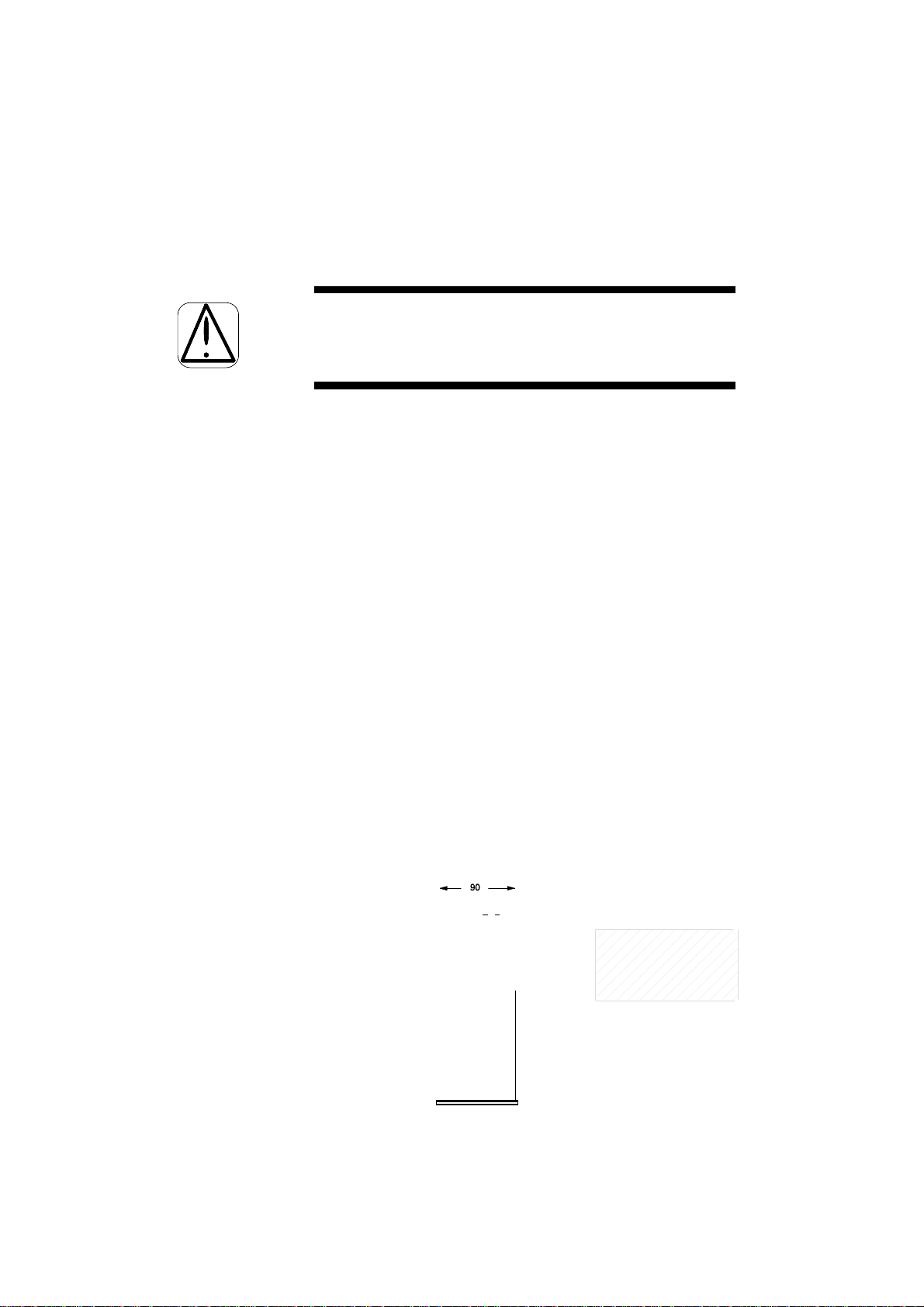
4.3 SWITCHING ON THE BACK-UP BATTERY
The PR 1612/02 is equipped with a lithium
back-up battery for its RAM. It is switched
off upon delivery.
In order to save the data of the RAM
after having put the PR 1612/02 into
operation, the battery must be switched
on by closing solder link BAT on the
main board before calibration.
Refer also to part 5.5.2.
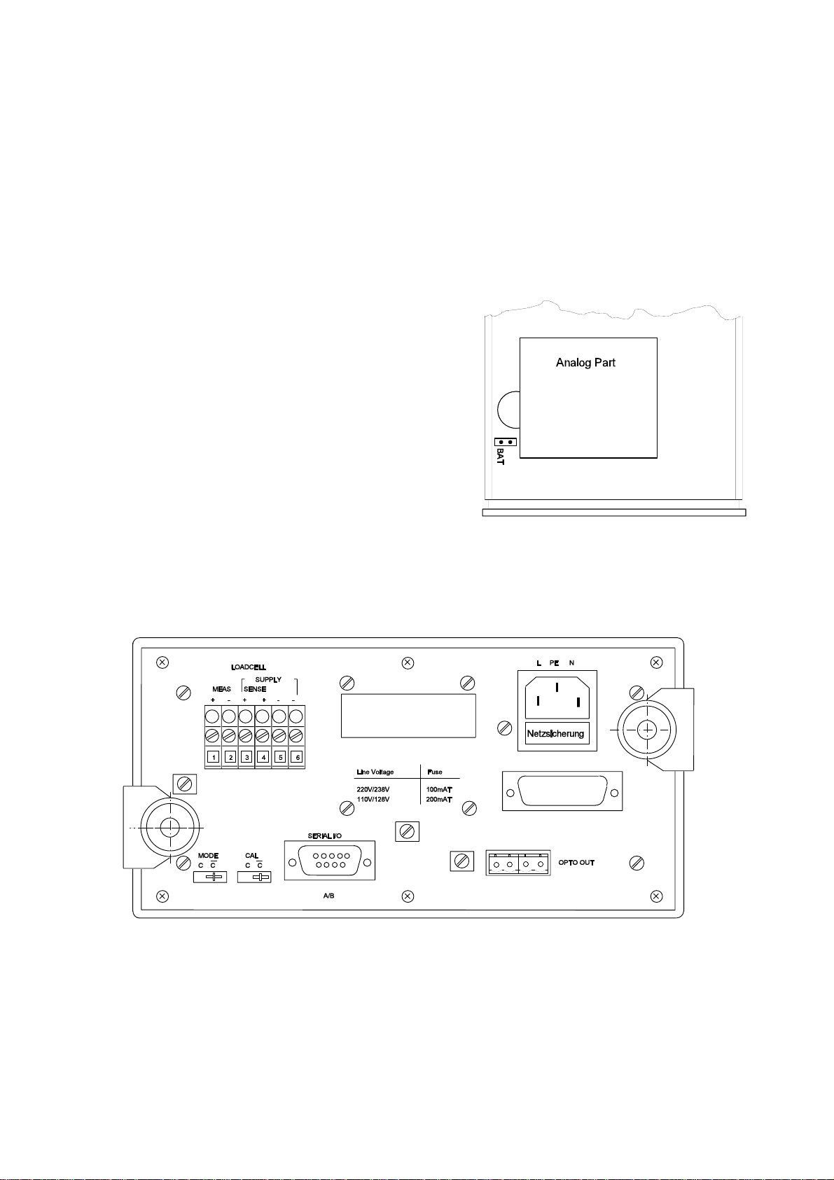
4.4 CONNECTION POSSIBILITIES
All connection facilities are located at the rear of the instrument.
OPERATING MANUAL PR 1612/02, Rel. $$ 2.30 Page: 4 - 3
4.5 CONNECTION OF MAINS AND SUPPLY VOLTAGES
The PR 1612/02 is connected to the mains via the 3 -pole connector at the rear of the
instrument.
Please note that the instrument has no mains switch, and therefore, is ready for operation as
soon as the mains is connected.
The instrument operates at mains voltages of 110,128, 220 and 238 V AC and 50/60 Hz.
Upon delivery it is set to 220 V AC.
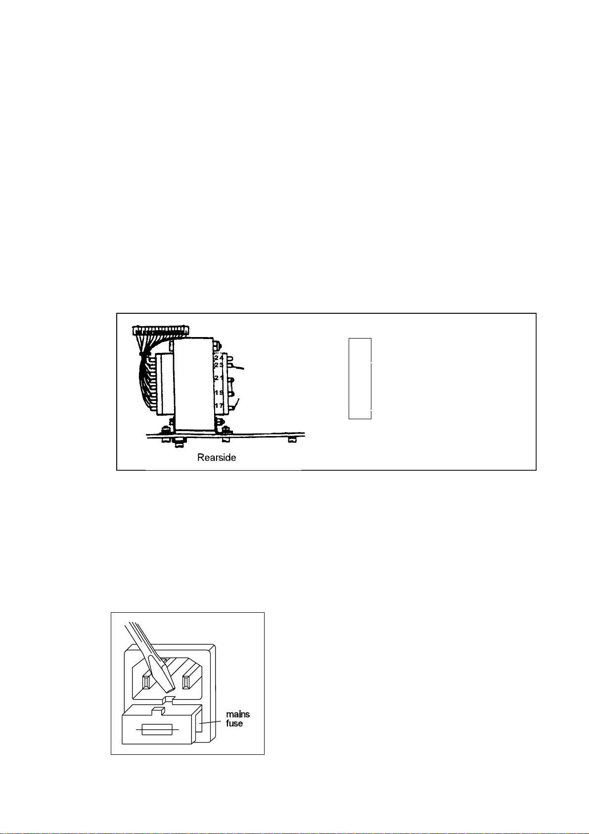
For changing of voltage, proceed as follows:
- disconnect the power,
- solder links on the transformer bobbin according to the following figure,
- replace the mains fuse inside the connector.
4.6 REPLACING FUSES
Before replacing fuses observe and follow the relevant safety instructions at para. 2.3 of this
manual .
The instrument is protected by means of a mains fuse which is located in the mains socket as
shown below.
nominal values service code number
------------------------------------------------------------110/128 V = 200 mA T 4822 070 32001
220/238 V = 100 mA T 4822 070 31001
OPERATING MANUAL PR 1612/02, Rel. $$ 2.30 Page: 4 - 4
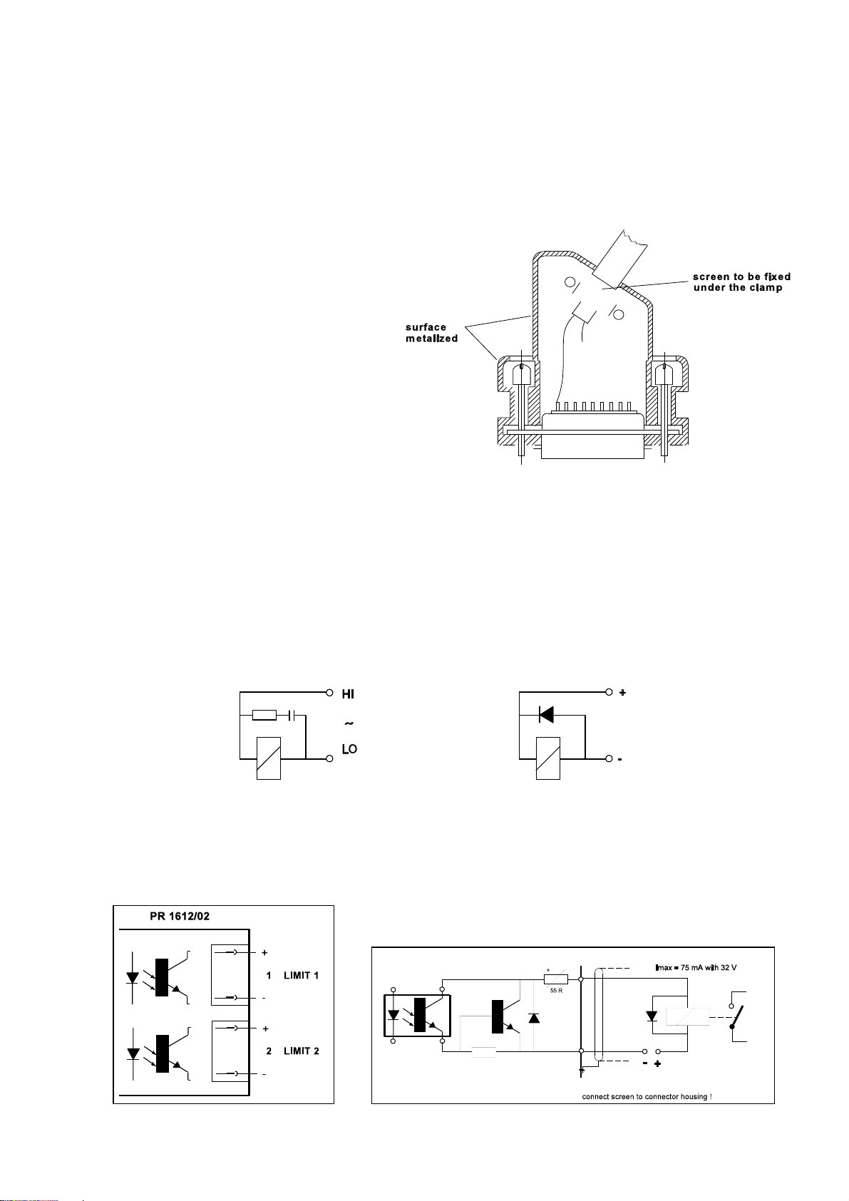
4.7 INSTALLATION INSTRUCTIONS FOR CONNECTING DATA CABLES
All cables transferring measuring
data and control signals must be
kept away from power cables and
should be screened.
The screen must be connected
to the housing of the connector
(see fig. below), or to the clamps
at the rear plate.
Relays and circuit breakers connected to the weighing system have to be spark suppressed as
follows:
- AC relays by means of an R-C combination (R = 100...300
parallel and as near as possible to the relay coil;
- DC relays by a reverse biased spark suppressing diode (e.g. BYX 10) connected in reverse
direction and in parallel and as near as possible to the relay coil.
4.9 CONTROL OUTPUTS
S, C~ 0.3 µF), connected in

OPERATING MANUAL PR 1612/02, Rel. $$ 2.30 Page: 4 - 5
4.9 THE PARALLEL INTERFACE
The PR 1612/02 Weight Indicators has a parallel interface. It can be equipped with the
interface options PR 1606, PR 1608/00 or PR 1608/10 (see also part 1.4.2) via which
corresponding subordinate or supervisory systems like remote displays, printer, recorder,
computer, or PLC's can be connected.
Mounting the interface options has to be performed as follows:
- open the indicator as described in part 4.3,
- plug in the required interface module into the socket of the parallel interface according to
the advices in part 7, and
- during configuration set up the PR 1612/02 by means of parameter C10, C12, or C17
as described in part 6.
Connections are different from module to module and have to be made as described in part
7 of this manual.
4.10 THE SERIAL INTERFACE
The PR 1612/02 Weight Indicator has one serial interface, which can only be equipped
with one of the following interface options at the same time:
- PR 1601 (20 mA current loop), o r
- PR 1602 ( RS 232), o r
- PR 1604 (RS 422/485).
Via a.m. interfaces corresponding subordinate or supervisory systems like remote displays,
printer, recorder, computer, PLC's can be connected.
Mounting the interface options has to be performed as follows:
- open the indicator as described in part 4.3,
- plug in the required interface module into the socket of line 1(A) o r line 2(B)
according to the advices in part 7, and
- during configuration set up the PR 1612/02 by means of parameter C04 .. C06, C10,
C14 .. C16, and C20 as described in part 6.
4.10.1 Connections
Connecting the serial interface and the inserted option must be performed via the 9-pol.
connector (DB9) at the rear of the respective indicator.
Application examples are shown in part 7.
Note !
The interface modules can only be connected via the pins as drawn in the following sketch.

OPERATING MANUAL PR 1612/02, Rel. $$ 2.30 Page: 4 - 6
4.11 CONNECTING THE LOAD CELLS
When selecting loadcells for connecting to the PR 1612/02, mind the criteria as given under
part 6.5.1 .
The loadcells must be connected by observing the following hints:
• Interconnecting loadcells and indicator of industrial weighing systems with cables of a
diameter up to 3mm should be done by using the PR 6130/01 junction box.
Type PR 6130/11 should be used in case of W&M approved systems.
• Before and during installation work make sure that no moisture enters the cables or
connections, especially of the loadcells and extension (measuring) cables and the
junction box (e.g. by water puddles, etc.).
• The connection of loadcells has to be preferably performed in 6-wire technique. The
cable must be connected to the instrument as shown in the diagram below.
• The screen(s) of the measuring cable has (have) to be taken to ground only at one side,
at the indicator.
• For connecting cables with different colour codes consult the respective data sheet.
• The wire strands of the cable must be twisted. They should be fixed to the terminals
without having been tinned or they should be provided with an appropriate crimp-type
cable connection.

OPERATING MANUAL PR 1612/02, Rel. $$ 2.30 Page: 4 - 7
• The permissible length of the extension (measuring) cable between loadcell and indicator
depends largely on the local conditions. According to the technical data the total length
should not exceed 300m.
4.12 EARTHING AND POTENTIAL EQUALIZATION
4.12.1 Earthing
The PR 1612/02 is protected according to class I (protective earth) of the IEC 348 and/or
VDE 0411 regulations. The connection cable must contain a protective earth conductor
which has to be connected according to the respective local safety regulations.
4.12.2 Potential equalization
If a potential equalization conductor is required, it must be connected to one of the clamps at
the rear of the instrument.
The diameter of the wire between indicator and the main equipotential bonding conductor
should be
$ 4mm².

OPERATING MANUAL PR 1612/02, Rel. $$ 2.30 Page: 5 - 0
CONTENTS OF PART 5 Page
5. OPERATING 5-1
5.1 SWITCHING ON/OFF THE INSTRUMENT 5-1
5.1.1 Switching on 5-1
5.1.2 Switching off 5-2
5.2 DESCRIPTION OF THE OPERATING CONTROLS 5-3
5.2.1 Keyboard 5-3
5.2.2 Status indicators 5-4
5.2.3 Front panel 5-4
5.2.4 Functions of the keys 5-4
5.3 ANALOG TEST 5-5
5.4 IN CASE OF AN ERROR 5-5
5.4.1 Display modes 5-5
5.4.2 Error messages 5-5
5.4.2.1 Error messages generated by wrong operation
or defective components 5-5
5.4.2.2 Error messages after power-on 5-6
5.4.2.3 Possible error messages during calibration 5-7
5.4.2.4 Possible error messages on communication 5-8
5.4.3 General error conditions 5-8
5.5 WARM START/COLD START 5-9
5.5.1 Warm start 5-10
5.5.2 Cold start (initial clear) 5-10
5.6 REPLACING FUSES 5-11

OPERATING MANUAL PR 1612/02, Rel. $$ 2.30 Page: 5 - 1
5. O P E R A T I N G
5.1 SWITCHING ON/OFF THE INSTRUMENT
5.1.1 Switching on
CAUTION !
Since the PR 1612/02 indicator has got no mains switch it can be operated and set-up as
soon as the mains voltage is applied.
The instrument is protected by a mains fuse which is located in the housing of the mains
connector (see page 4-3).
Before the PR 1612/02/00 is switched on for the first time, mains voltage adaptation and
installation must be finished (see part 4).
Therefore, check
• if the mains voltage adjustment is correct (see part 4.5),
• if all connections are correct (see parts 4.4 and following),
• if the back-up battery is switched on (see part 4.3)
After switching on, the indicator performs an internal test at first.
In case of a defect or a malfunction the PR 1612/02 generates a corresponding error
message.
An explanation of the particular messages can be found in part 5.4.
As part of the test the PR 1612/02 switches on all segments at its weight display module
during approx. two seconds.
If the internal test is completed successfully, the display shows for some seconds the type of
indicator.
For example:
PR 1612
Then, for a couple of seconds, it shows the type of software inserted.
For example:
00-2=30
If enabled by means of a licence number, the corresponding 'SW-option' will be displayed
now.
For example:
13=05

OPERATING MANUAL PR 1612/02, Rel. $$ 2.30 Page: 5 - 2
Thereafter, the program changes the weight value display over to the
NORMAL WEIGHING MODE.
For example:
Symbol appears as soon as the weight does not change any more (standstill display).
After about 60 minutes warm-up time, set-up and/or calibration work may begin.
5.1.2 Switching off
With obvious defects of the instrument, or with repairs/changes, the mains supply voltage
must be disconnected by removing the mains connector.
In case of trouble, e.g. with the communication to superordinate or subordinate system
components interrupted or blocked, we recommend interrupting the mains (supply) voltage
in order to carry out a "warm" or "cold" start (refer to part 5.5).
00654kg

OPERATING MANUAL PR 1612/02, Rel. $$ 2.30 Page: 5 - 3
5.2 DESCRIPTION OF THE OPERATING CONTROLS
5.2.1 Keyboard
KEY REMARK
TEST
Pressing causes an analog self-check, dependent of selected check mode
either a
- display of an analog test figure, or
- display of the difference between F.S.D. and analog test number, or
- the checksum of the EEPROM.
GROSS MODE
Switches display to gross weight as long as key is pressed.
The gross weight display will be confirmed additionally by status indicator B.
TARE MODE
Switches display to tare as long as key pressed and provided it has
previously been tared. This will be confirmed by a lit status indicator T.
When releasing the key again, the actual net weight will be displayed,
confirmed by lit status indicator NET.
SET TARE
Pressing moves the actual gross weight into the tare memory (taring),
provided that:
- the weight is in 'standstill', and the weight value is 'in range', i.e.
< f.s.d. and > 0,
- the instrument is not in failure mode, and
- a test has not been activated.
Consequently, the weight display changes automatically to NET mode,
indicated by lit status indicators NET .
RESET TARE
Pressing clears the tare memory and switches the display to gross weight
display.
ZERO
Pressing sets the gross weight to zero with an accuracy of ±1/4d, provided
the weight is in standstill mode,
- the gross weight is in the ZERO SET RANGE (selectable up to +/- 255d),
i. e. the centre-of-zero status indicator is lit.
PRINT
Print weighing document (configurable via parameter C10, C15 and C22).

OPERATING MANUAL PR 1612/02, Rel. $$ 2.30 Page: 5 - 4
5.2.2 Status indicators
for centre of zero indication, (within ± 1/4 d)
standstill
B gross on display
NET net on display
T tare on display
5.2.3 Fron t panel
5.2.4 Functions of the keys
The 7 keys below the weight value display have set-up function in addition to the operating
function.
Please note:
A page with adhesive strips on which the additional functions of the keys are marked in
various languages is included in this Instruction Manual.
If required, cut a strip in the required language, fit it below the keys and remove it after
adjustment (configuration).

OPERATING MANUAL PR 1612/02, Rel. $$ 2.30 Page: 5 - 5
5.3. ANALOG TEST
During CALIBRATION of the indicator, an analog test value will be automatically determined
and stored in the EEPROM (C46. .C49) . This value should also be written down (see also
C58) in order to be able to compare it with the current test value.
When the analog test is activated, the measuring signal of the load cells will be
disconnected from the input of the instrument.
If the test is performed by pressing key the display will show the following values,
depending on the initiated type of test:
a. either the current test value (which is to be compared with the original value),
or
b. the difference between the originally stored test value and the current test value,
or
c. a checksum of the EEPROM (required inter alia for Switzerland ).
If the test is automatically activated, it will be repeated after a period of 1 to 24 hours that
can be preselected during calibration.
In case of an error, the test will be continuously repeated. If the deviation will still be too
great, the instrument must be switched off and the Customer Support of the local
Organization of Philips Weighing must be informed.
5.4 IN CASE OF AN ERROR
5.4.1 Display modes
5.4.2 Error messages
5.4.2.1 Error messages generated by wrong operation or defective components.
They will automatically be indicated, or when selecting parameter C29.
Display via parameter C29 e.g.
K02 ,A=0

OPERATING MANUAL PR 1612/02, Rel. $$ 2.30 Page: 5 - 6
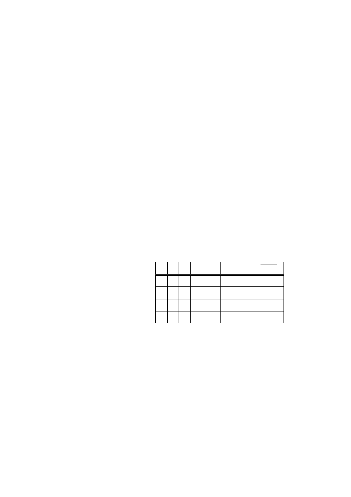
Error code standard RAM EPROM EEPROM
H= 00
H= 01 X
H= 02 X
H= 03 X X
H= 04 X
H= 05 X X
H= 06 X X
H= 07 X X X X = faulty
Error code cause / meaning
A = 1 (Err 1) Internal number domain overflow, e.g. by wrong calibration, by the input
voltage being too high, or because of a checksum error in a total weight
buffer.
A = 2 (Err 2) Measuring value higher than f.s.d. + overload.
A = 3 (Err 3) Hardware error in the ADC (e.g. open measuring input or analog circuit
disconnected from digital circuit, or analog circuit without voltage supply).
A = 4 (Err 4) Checksum error during A/D conversion.
A = 5 (Err 5) Internal number domain underflow, e.g. by wrong calibration, or by the in-
put voltage being too low.
A = 6 (Err 6) Overload of the ADC (measuring voltage too high or wrong SPAN adjust-
ment).
A = 7 (Err 7) Negative input voltage at ADC (wrong polarity of the measuring voltage).
A display of
indicates that the actual board number in parameter C82 has been reset.
Please contact the Customer Support of your local Philips Weighing Organization.
5.4.2.2 Error messages after power-on
A display of
indicates lost RAM data, because:
- battery not switched on via link BAT, or
- battery low voltage (should be > 3V), or
- battery defective, or
- of a program(EPROM) change, or
- of external disturbances.
Refer to hints in part 5.5.
no Dat
(OLD !!

OPERATING MANUAL PR 1612/02, Rel. $$ 2.30 Page: 5 - 7
A display of bat
for approx. 6 seconds after power-on
indicates that the back-up battery has either not been switched-on, or that its voltage is too
low, i.e. there is a risk of data loss.
The battery voltage has to be checked from time to time, or has to be checked by the
Customer Support of the local Organization of Philips Weighing in connection with a system
test.
If necessary, the battery must be replaced and to be disposed of acc. to the official
regulations.
A display of
indicates an interrupted access to the board number.
Please contact the Customer Support of your local Organization of Philips Weighing
immediately, as the possibly activated SW option PR 1613/05 can not be used any more.
A display of
indicates a malfunctioning or a physical defect of
the inserted EEPROM. Please contact the Customer Support of your local Organization of
Philips Weighing.
5.4.2.3 Possible error messages during calibration
A display of
indicates one of the following possible calibration errors:
Display Remark with: in step:
CErr 1 step: C35 }
error: entered CAL weight > f.s.d. }
e.g. f.s.d. = 1500 kg }
cal. weight = 2000 kg }
CErr 2 error: meas. signal too low for calibration }
(< 0.2mV). }
CErr 3 step: C35 } NEXT weighing
error: meas. signal too high. Sum of deadload } STEP mode
signal and determined meas. signal are }
out of scale, or }
step: C37 }
error: zero point correction too far in pos. }
direction. With maximum meas. input }
the scale range will be exceeded. }
board !!
EEPROA!!
(Err
proceed instrument
}
}

OPERATING MANUAL PR 1612/02, Rel. $$ 2.30 Page: 5 - 8
proceed instrument
Display Remark with: in step:
CErr 4 stop: C35 }
error: too less measuring voltage per scale }
step, i.e. desired resolution too high. }
} NEXT weighing
CErr 5 error: no standstill during calibration } STEP mode
}
CErr 8 step: C35 }
error: resolution too high (see also 6.5.2) }
CErr 9 step: C83
error: wrong license number.
Only valid for SW-option PR 1613/05.
A display of
appears when a calibration with
a negative measuring signal will be started.
5.4.2.4 Possible error messages on communication
Refer to part 8.3.7.1
5.4.3 General error conditions
condition possible fault how to solve
Display totally dark • mains interruption check,
• mains fuse defective } mind hints in
• instrument defective } part 2
Display confused • RAM - error check battery,
• processor disturbed perform WARM-start,
• bad contacts contact Service
No communication to • wrong interface module }
supervisory or slave • wrong interface setting }
system(s) • no supply of the interfaces } check
• incorrect connection }
• bad contacts }
neg-adu
• protocols not properly see part 8.
• bad contacts check connectors/
terminals.

OPERATING MANUAL PR 1612/02, Rel. $$ 2.30 Page: 5 - 9
condition possible fault how to solve
Communication to • C04..C14 not properly set check
supervisory • hang-up due to external
or disturbances. perform WARM-start.
slave system(s) • protocols not properly see part 8.
disturbed • interface modules defective contact Service
Weight display • mechanical problems } check at pipes,
unstable at the } bellows, hoses and
weighing device } constrainers for dirt.
• bad connections } check connectors/
} terminals.
• not properly controlled air }
pressure conditions in } check valves
container and pipes }
• Ioadcell(s) defective contact Service
Changed zero point • mechanical modification } check and if so correct
at the weighing device } by means of C37
• Ioadcell(s) defective/overloaded contact Service
Weight display wrong • calibration data lost check position of switch
• not properly controlled air check valves, bellows,
pressure conditions in and
container pipes .
• calibration changed perform new calibration
• Ioadcell(s) defective contact Service
Set-up not possible • switch CAL not in position C check and correct
• code word in C21 enter correct one
5.5 WARM START / COLD START
A "WARM" or "COLD" start is always carried out when switching on the mains voltage.
Whether "WARM" or "COLD" start, depends on the position of switches CAL and MODE on
the instrument rear or bottom respectively.
CAL and the battery,
compare settings
by means of previous
print-out (C58).
During normal operation, switches MODE and CAL are normally in position
¯c.

OPERATING MANUAL PR 1612/02, Rel. $$ 2.30 Page: 5 - 10
5.5.1 Warm start
A "WARM START" is purposeful e.g. with the instrument processor stopped due to external
disturbances (display of Err..), or with the communication sequence to other system
components interrupted.
- MODE position:
- CAL position:
5.5.2 Cold start (initial clear)
- MODE position: C 1. INITIAL CLEAR, all data in RAM will be
- CAL position: C the instrument uses the default
For instance, a "COLD START" must be carried out with message
¯c instrument uses the configuration
¯c instrument uses the calibration
(old !!
displayed after instrument switch-on.
parameters entered last.
parameters stored last.
reset, and therefore
2. the instrument uses the default
configuration settings.
calibration settings.
This message indicates that RAM data are lost and that the instrument must be re-initialized
by means of a cold start.
Possible causes are e.g.:
- jumper BAT on the main board not fitted, i.e. the back-up battery for the RAM is not
connected (see following figure), and
the RAM data are therefore not protected.
- back-up battery is empty or back-up battery voltage too low (see part 5.4.2.2).
- software was changed (e.g. by EPROM replacement), or
- RAM data lost due to external influences.
A 'cold start' has to be performed as follows:
1. Open the instrument
2. Close jumper BAT
3. Select supply voltage for load cells (see chapter 6.5.1)
4. Close instrument
5. Switch MODE to position: C } default configuration parameters and
6. Switch CAL to position: C } default calibration parameters will be activated
7. Switch power-on
8. Switch MODE to position: ¯c

OPERATING MANUAL PR 1612/02, Rel. $$ 2.30 Page: 5 - 11
9. Perform calibration after 60 minutes warm-up time (see next pages).
10. Store the entered parameter, see chapter 6.6
11. Switch CAL to position: ¯c
12. Enter configuration parameter
Please note:
Very often malfunctions of the indicator can simply be removed by resetting the RAM.
For this
- move switch MODE to position C,
- keep switch CAL in position ¯c, and
- switch off/on the mains supply.
All data in the RAM will be reset to its initial state.
Performing this kind of cold start the calibration data in the EEPROM will not be influenced,
and consequently re-calibration will not be necessary.
5.6 REPLACING FUSES
Before replacing fuses follow the relevant instructions in parts 2.3 and 4.7 of this manual.

OPERATING MANUAL PR 1612/02, Rel. $$ 2.30 Page: 6 - 0
CONTENTS OF PART 6 Page
6. SETTING THE INDICATOR 6-1
6.1 PROCEDURE 6-1
6.1.1 Selecting the set-up level 6-1
6.1.2 Changing the parameter code 6-2
6.1.3 Changing the parameter-value 6-2
6.1.4 Display of the next parameter-code 6-2
6.1.5 Leaving the set-up level 6-2
6.1.6 Leaving the set-up level and storing the calibration data 6-2
6.2 SHORT SURVEY OF THE CONFIGURATION PARAMETERS 6-3
6.3 CONFIGURATION 6-3
6.3.1 Sequence 6-4
6.4 SHORT SURVEY OF THE CALIBRATION PARAMETER 6-10
6.5 CALIBRATION 6-10
6.5.1 Input signal range (loadcell rating) 6-10
6.5.1.1 How to determine the deadload signal 6-11
6.5.1.2 How to determine the measuring signal 6-11
6.5.1.3 How to set the loadcell supply voltage 6-11
6.5.2 Important advices for calibration 6-12
6.5.3 Calibration procedure 6-13
6.5.4 Calibration by means of calibration weights 6-16
6.5.5 Incremental calibration with make-up weights 6-18
6.5.6 Checking the linearity (accuracy) of the scale 6-20
6.5.7 Setting, modifying, or re-entering zero point, scale end, and
span value without calibration weights 6-20
6.5.7.1 Modific. of the zero point setting at an empty scale 6-21
6.5.7.2 Re-entering the last valid zero point setting at a
loaded scale 6-22
6.5.7.3 Re-entering the last valid scale end and span value
at a loaded scale 6-23
6.5.7.4 Setting zero point, scale end, and span value
without calibration weights 6-24
6.5.8 Continuation of the calibration procedure 6-26
6.6 PROTECTING/STORAGE OF ENTERED CALIBRATION DATA 6-33
6.7 SET-UP LIST (including of default values) 6-34
6.7.1 Print-out example of the default values 6-36
OPERATING MANUAL PR 1612/02, Rel. $$ 2.30 Page: 6 - 1
6. S E T T I N G T H E I N D I C A T O R
The indicator must be allowed to warm up during approx. 60 minutes
before any settings are carried out
Setting the PR 1612/02 indicator will be performed by means of:
- CONFIGURATION - parameters, and
- CALIBRATION - parameters.
CONFIGURATION parameters contain non-system-specific data stored in RAM.
The y a r e protected against mains failure by a back-up battery, the voltage of which must be
checked from time to time.
Configuration parameters can also be protected against operator error (write-protected) by a
code number in parameter C21. Data in parameter C01 (Year, date, and time) are not
protected.
CALIBRATION parameters contain system-specific data, which can be stored in an EEPROM
and thus be protected against mains failure.
Moreover they can be write protected when switch CAL at the instrument rear or bottom is in
position
¯c .
6.1 PROCEDURE
6.1.1 Selecting the set-up level
- move switch CAL and MODE to position C
- press keys EXIT and (B+T) simultaneously
- display of:
•
(01

OPERATING MANUAL PR 1612/02, Rel. $$ 2.30 Page: 6 - 2
6.1.2 Changing the parameter code
•
- display of e.g.
- change to the next parameter by pressing key NEXT STEP , or
- move directly to the next desired parameter by:
- position the cursor (indicated by flashing digit • ) by means of keys and
to the desired decade. If the cipher does not flash, parameter is possibly write- protected
(CAL on ¯c , or C21 coded).
- change parameter code by means of key or
- accept parameter code by pressing key NEXT STEP
6.1.3 Changing the parameter value
- display of e.g.
- position the cursor (indicated by flashing digit • ) by means of keys and
to the desired decade. If the digit does not flash, parameter is possibly write-protected
(CAL on ¯c , or C21 coded).
- select value by means of key or .
Repeat that for each digit position (decade).
(01
•
( 12,00
- accept parameter value by pressing key NEXT STEP .
6.1.4 Display of the next parameter code
- display of e.g.:
- start again at point 2 (6.1.2)
6.1.5 Leaving the set-up level
- press key EXIT in order to leave the set-up level
Note:
If switch CAL in pos.
if switch CAL in pos. C, follow hints at part 6.1.6.
6.1.6 Leaving the set-up level and
- after pressing key EXIT
¯c , the display changes immediately to the actual weight value,
storing the calibration data
•
(02
- during approx. 3 seconds display of:
Store ?

OPERATING MANUAL PR 1612/02, Rel. $$ 2.30 Page: 6 - 3
•
- then change to :
•
- using key modify into:
remaining on no means 'no storage of entered data' !
- press key EXIT
- display changes to:
- set switch CAL to position ¯c
6.2 SHORT SURVEY OF THE CONFIGURATION PARAMETER
C00 without function
C01 year, date, and time
C02 without function
C03 without function
C04° line 1/A Baudrate
C05° linie 1/A XON/XOFF
C06° line 1 7/8 databit and parity
C07 without function
C08 without function
C09 without function
C10° configuration of l/O data
C11 not used
C12° configuration of PR 1606 and
PR 1608
C13° provided for PR 1613/05 only
C14° remote display on/off
C15° configuration of print out
C16° setting number of weight ticket
C17° analog output of PR 1606,
C18 without function
C19 without function
C20° controlling a W&M approved printer
C21 write-protection code number
C22° instrument address A .. Z
C24° disable key functions
C25° limit 1, on value
C26° limit 1, off value
C27° limit 2, on value
C28° limit 2, off value
C29 error display
( no
( Yes
AlldAt
0/20mA (0/10V), or 4/20mA (2/10V)
° can be write-protected by a code number in parameter C21.
6.3 CONFIGURATION
In order to configure the instrument, no settings by means of switches must be carried out.
If it should not be possible to modify parameter values, they perhaps are write-protected by a
code number in parameter C21 (see also part. 6.3.1, C21).
By pressing keys B and T simultaneously, the program jumps from the normal weighing
mode to the set- up level and displays the first parameter C00 (see also parts. 6.1.1 to
6.1.6).
Select the required parameter and enter the desired values/data by pressing the keys as
specified below.

OPERATING MANUAL PR 1612/02, Rel. $$ 2.30 Page: 6 - 4
Selecting a specific parameter can also be done directly, i.e. independently of the order listed
below. For this, change the displayed parameter digit into the required one and press key
NEXT STEP ( ) .
After set-up, store the data according to the instruction in part 6.6 and protect them against
accidental alteration and mains failure by setting switch CAL into position
6.3.1 Sequence
Switch on back-up battery (refer to part 4.3)
press keys EXIT and (B+T) simultaneously, in order to change from weighing mode to
set-up level.
¯c.
•
display of e.g. parameter
(• means flashing digit)
press key NEXT STEP
YEAR, DATE, and TIME
press key NEXT STEP
display of :
enter actual year, e.g:
press key NEXT STEP
display of :
enter actual date in DD,MM, e.g.:
(00
•
(01
•
(y ====
•
(y 1996
•
(d ==.==
•
(d 28,05
press key NEXT STEP
display of :
enter actual time between 00,00 .. 23,59, e.g.:
press key NEXT STEP
unrealistic data will not be accepted!
•
(t ==,==
•
(t 19,15

OPERATING MANUAL PR 1612/02, Rel. $$ 2.30 Page: 6 - 5
•
LINE 1: BAUD RATE
press key NEXT STEP
Note:
If this parameter and the following ones are write-protected by means of a code number in
parameter C21, digit 4 does not flash. If so, select parameter C21 directly and enter the
correct code number.
In this case
display of parameter
press key NEXT STEP
enter correct code number
if correct, for some seconds display of: Good
if faulty, for some seconds display of: FAIL
Note !
If the correct number was lost or is not available
any more, contact your local Philips Weighing Customer Support.
(04
(21
When performing a 'cold start' (switch MODE in position C and power off/on), the code
number in C21 can be cleared, but
all previously entered data protecte by C21 are also reset to the default data.
For setting parameter C21, refer to the following procedure.
press key NEXT STEP
display of parameter
by means of keys and go back to parameter C04 and continue with the
configuration as follows:
Note:
Parameter marked with sign ° , will be write-protected if C21 is set accordingly.
(22

OPERATING MANUAL PR 1612/02, Rel. $$ 2.30 Page: 6 - 6
Parameter Function Data Default value
C04° line 1: baud rate 300 .. 9600 4800bd
C05° line 1: XON/XOFF 0=off, 1=on 0
C06° line 1: 7/8 bit and parity 0 = 7 / even 0
1 = 8 / even
2 = 7 / odd
3 = 8 / odd
4 = 7 / none
5 = 8 / none
C10° serial output functions 1 = printer via line 1(A) 1
(witout hand shake mode),
or
remote display via line 2(B)
2 = printer via line 2(B)
(with hand shake mode)
3 = Communication mode via line 1(A)
Note !
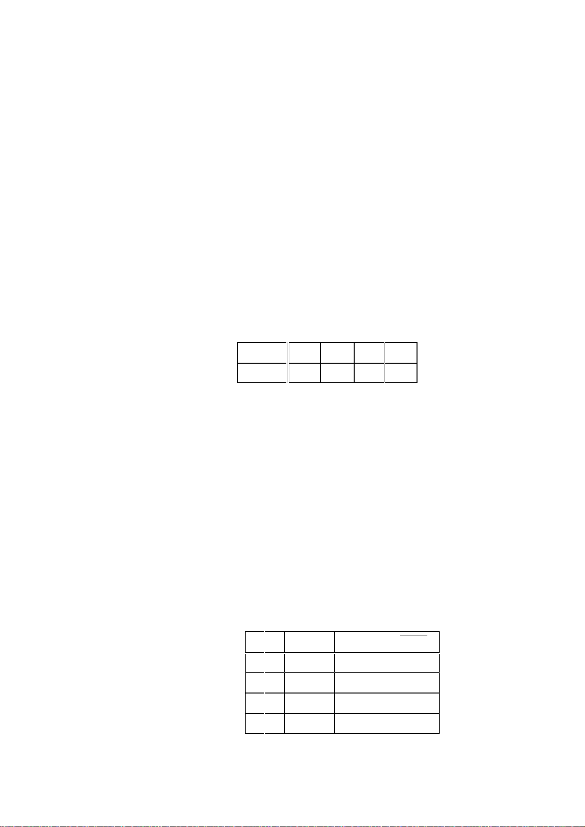
mode C10 C14 C15 C20 C53
---------------------------------------------------------------------------------------------printer without hand shake 1 off on on/off off
via line 1(A)
or
remote display via line 2(B) 1 on off off off
---------------------------------------------------------------------------------------------printer with hand shake 2 off on on/off off
via line 2(B)
---------------------------------------------------------------------------------------------communication 3 off off off on
via linie 1(A)
Parameter Function Data Default Value
C12° analog output 0 = output of gross value 0
of PR 1606, or 1 = output of net value
BCD output 2 = output of tare value
of PR 1608 3 = value as shown at front
display (G or N or T)
4 = absolute net values with sign
on SPM address 1.7.
5 = like 3, but with absolute
net value like 4.
Note !
When using the PR 1606:
- only an output signal of positive weight values will be generated,
- if the gross weight will be > f.s.d + Amax, or at the indication of ERR1, 2, 3,
or 6, the last valid output signal will be kept, until the value falls below a.m.
limits again.

OPERATING MANUAL PR 1612/02, Rel. $$ 2.30 Page: 6 - 7
- if the gross weight is < ±¼ d, or with the indication of ERR4, 5, or 7, the
output signal remains on 'zero' level signal as selected by C17, until < ±¼ d
will be exceeded again.
- after taring in output mode 1 and 3 (weight display and output signal = net)
the output signal will be kept at 'zero' level, if the net weight becomes
negative.
Parameter Function Data Default value
C13° not provided for standard PR 1612/02 software, only
for SW option PR 1613/05. Please refer to corresponding manual.
C14° type of remote display 0 = off 0
protocol 1 = PR 1577/..- protocol on
2 = PR 1627/PR 1628 protocol on
Note:
The remote display protocol runs only via an interface in
line 2 (B).
C15° configuration of the 0 = print out (00000) 41000
weighing ticket. 1 = print out of gross weight
The sequence of the 2 = print out of net weight
weight data can be 3 = print out of tare weight
defined and combined 4 = print out of date and time
as mentioned. 5 = print out of current ticket number
6 = CR/LF
7 = address of device 'A...B'
(observe C22)
Note:
- In order to print net and tare values, the PR 1612/02 must be tared
previously.
Examples of print out sequences (in W&M mode):
Configuration: 41000
26.03.1996 20:08 <01000 kg>N
Configuration: 41200
26.03.1996 20:10 <01000 kg>B <00600 kg>N
Configuration: 41230
26.03.1996 20:12 <01000 kg>B <00600 kg>N <01000 kg>T
Configuration: 41235
26.03.1996 20:08 <01000 kg>B <00600 kg>N <01000 kg>T #00001

OPERATING MANUAL PR 1612/02, Rel. $$ 2.30 Page: 6 - 8
Parameter Function Data Default value
C16 ° current number of 0 .. 65536 000000
weigt ticket, or
configuration parameter
for PR 1613/10.
The first print-out starts with the adjusted digit + 1.
C17° span of the analog 0..20 mA, 0..10 V = 0 0
output module PR 1606 4..20 mA, 2..10 V = 1
C18 without function
C19 without function
C20° W&M-approved 0 = off, 1 = on 0
printer on/off
C21 write-protection code 0001 .. 9999 0000
number 0000 = no write protection
Note:
- the write-protection will be activated after exit from the configuration level.
- if write-protected the parameter values will be displayed, but
cannot be modified.
- in case of need follow hints as mentioned before parameter C04.
C22° address of the A .. Z A
PR 1612/02 to a
printer or remote
display unit.
C23 not used
C24° disable key functions 0000 = all keys enabled 0000
0001 = analog test }
0002 = gross weight }
0004 = tare weight }
0008 = tare set }
0016 = tare reset } disabled
0032 = zero setting }
0064 = print }
0128 = B+T }
0256 = without function }
e.g. 0097 = (1+32+64) = functions 'analog test + zero setting + print' will be
disabled.
Note:
Disabled key functions can be released by a 'cold start'.
C25 .. 28° Limit values "LIM1/LIM2"
(For connections refer to part 4.11.2)

OPERATING MANUAL PR 1612/02, Rel. $$ 2.30 Page: 6 - 9
Note:
If the on value is set equal to off value, the following switching conditions
are valid:
• LIMIT 1 output is active if weight > set value
• LIMIT 1 output is switched off if weight
• LIMIT 2 output is active if weight < set value
• LIMIT 2 output is switched off if weight
# set value
$ set value
Parameter Function Data Default value
C25° Alarm switch-on 00000 (off) .. scale end value 00000
threshold for
limit value 1 (LIM 1)
C26° Alarm switch-off 00000 (off) .. scale end value 00000
threshold for
limit value 1 (LIM 1)
C27° Alarm switch-on 00000 (off).. scale end value 00000
threshold for limit
value 2 (LIM 2)
C28° Alarm switch-off 00000 (off) .. scale end value 00000
threshold for limit
value 2 (LIM 2)
C29 Error messages (see Part 5.4.2.1) H00, A=0
Should the set-up level have to be left after having finished the configuration, press key
B (EXIT) instead of key (NEXT STEP).
The display moves automatically to the normal weighing mode.
Switch MODE (and CAL) must be set to position
¯c after having left the set-up level !

OPERATING MANUAL PR 1612/02, Rel. $$ 2.30 Page: 6 - 10
6.4 SHORT SURVEY OF THE CALIBRATION PARAMETERS
C30° Decimal point C51° Min. weight limit for print-out
C31° Dimension kg/t/g/lb C52° Switch-over point of a multi-range scale
C32° Step width C53° Communication protocol
C33° Overload value C54° Slave address for communication mode
C34° Measuring time C55° Weights & measures operation
C35° Measuring range C56° without function
C36° Display multiplied by 10, magnifier C57° Analog filter
C37° Deadload suppression without C58 Configuration and calibration parameter
re-calibration print-out
C38° Deadload suppression by mV/V- C59° Multi-range scale in gross/net mode
setting
C39° Calibration by mV/V-setting C80 Display of the already used part of
C40° Standstill range the 'zero setting range' C42.
C41° Standstill time C82 Display of the 'board number'.
C42° Zero setting range C83 Entry of PR 1613/05 licence number
C43° Automatic zero tracking range C84 Reset of Licence number(s)
C44° Automatic zero tracking step width C85 without function
C45° Autom. zero tracking interval time C86 without function
C46° TEST-mode of analog-test, C90..95 without function
C47° TEST-key function C96 Test number for factory-internal use
C48° Tolerance of test value C99 Display of all enabled SW versions
C49° Repetition time for an autom. test
C50° Generation of test value for an
automatic test
° will be write-protected by setting switch CAL to position ¯c , and by a code number in C21
6.5 CALIBRATION
6.5.1 Input signal range (loadcell rating)
When selecting the loadcell(s) mind the following rating criteria:
• the PR 1612/02 can be set for 12 V or 20 V loadcell supply voltage (refer to 6.5.1.3),
• the signal from the loadcells (dead load signal plus measuring signal) may be 36mV at
maximum,
• for OIML class C3 (Ill) the minimum measuring signal must be
2.4 mV with 12V loadcell supply voltage, or
6.0 mV with 20V loadcell supply voltage.
With PHILIPS load cells which are not installed in a hazardous area it is recommended to
use a 20 V loadcell supply, provided the 36 mV input signal will not be exceeded.
CAUTION !
Loadcells in an hazardous area must be supplied by only 12 V.

OPERATING MANUAL PR 1612/02, Rel. $$ 2.30 Page: 6 - 11
6.5.1.1 How to determine the deadload signal
The deadload signal must not exceed 33.6mV.
If the value of the deadload signal is unknown, it can
- either be measured by means of a digital voltmeter at e.g. the loadcell connector,
- or it can be evaluated by using the PR 1612/02 itself, and as follows:
switch on the PR 1612/02 with CAL switch in position C ( default values ! ), and
calculate by means of formula
displayed value x 1mV/V x loadcell supply voltage [V]
deadload [mV] = ----------------------------------------------------------------------------
Example:
- loadcell supply voltage: 20 V
- displayed deadload after cold start: e.g. 2000 kg
This corresponds to a deadload signal of 2000 x 12mV/ 3000 = 8 mV
3000
6.5.1.2 How to determine the measuring signal
The measuring signal can be calculated by means of formula
full scale deflection x loadcell sensitivity [mV/V] x loadcell supply voltage [V]
meas. signal [mV] = ---------------------------------------------------------------------------------------------------
nominal load of one loadcell x number of loadcells
Example:
- full scale 60000 kg
- loadcell supply voltage 20 V
- nominal load of one loadcell 20 t
- number of loadcells 4
- sensitivity of one loadcell 1 mV/V
60000 kg x 1 mV/V x 20 V
measuring signal = ----------------------------------- = 15mV
20000 kg x 4
Result of the examples:
The maximum signal from the loadcells is 4 mV + 15 mV = 19 mV, and would therewith be
within the range up to 36 mV as required !
6.5.1.3 How to set the loadcell supply voltage
Upon delivery from the factory the PR 1612/02 is set for 12 V supply voltage.
Note:
Take care that jumper on the main board and switch at the analog part are in the correct
position (12V or 20V). The indicator will also work when jumper and switch are in different
positions, but with lower accuracy.

OPERATING MANUAL PR 1612/02, Rel. $$ 2.30 Page: 6 - 12
6.5.2 Important advices for calibration
setting facilities
voltage jumper on PCB switch at analog part
----------------------------------------------------------------12 V closed in lower position
20 V open in upper position
• The calibration of the indicator can be performed by different methods:
- by means of calibration weights via the whole scale range (see part 6.5.3), or
- by means of calibration weights and material, i.e by 'incremental calibration with makeup weights' (see part 6.5.5 and appendix A2), or
- without calibration weights by entering the respective mV/V value (see part 6.5.7).
• The calibration weight must generate a measuring voltage of
calibration will not be accepted by the indicator and an error message CErr 2 is
generated.
Example: loadcell sensitivity 1mV/V
number of loadcells 3
nominal load of one l.c. 1000kg
loadcell supply 20V
calibration weight 120kg
120 kg x 1 mV/V x 20 V
measuring signal = --------------------------------- = 0.8 mV (which is sufficient)
3 x 1000 kg
• The following maximum resolutions of the scale range (f.s.d. : step width) are possible:
- 3000d acc. to OIML class lll (EC type approval)
or
for industrial applications (not W&M approved)
- 48000 counts with step width 1, or
- 30000 counts with step width 2, or
- 12500 counts with step width 5, or
- 9999 counts with step width 10
$ 0.2 mV. Otherwise the
When exceeding the possible maximum resolutions an error message CErr 8 will be
generated, and the calibration procedure will be aborted.

OPERATING MANUAL PR 1612/02, Rel. $$ 2.30 Page: 6 - 13
• During calibration the following error messages might be displayed:
Display Remarks proceed instrument
with in step
CErr 1 step: C35 }
error: entered weight value > f.s.d }
e.g. f.s.d = 1500 kg }
weight value = 2000 kg }
}
CErr 2 error: meas. signal too low for calibration }
(< 0,2mV) }
}
CErr 3 step: C35 }
error: meas. signal too high. Sum of deadload }
and determined meas. signal is out of scale, }
or }
step: C37 } NEXT weighing
error: zero point correction too far in positive } STEP mode
direction. With max. meas. input signal }
the scale range will be exceeded. }
}
CErr 4 step: C35 }
error: too low measuring voltage per scale step, }
i.e. desired resolution too high. }
}
CErr 5 error: no standstill during calibration. }
}
CErr 8 step: C35 }
error: resolution too high }
CErr 9 step: C83
error: wrong license number.
Only valid for SW option PR 1613/05.
6.5.3 Calibration procedure
For the calibration of the PR 1612/02 set switch CAL on the instrument rear to position C.
Otherwise a calibration is not possible, but only a display of the adjusted data (values) !
After setting, store the data according to the instruction in para. 6.6 and protect them against
accidental alteration and mains failure by setting switch CAL into position
Move switch CAL to position C
Press keys EXIT and (B+T) simultaneously, in order to change from weighing mode to
set-up level.
display of e.g. parameter
(• means flashing digit)
¯c .
•
(00

OPERATING MANUAL PR 1612/02, Rel. $$ 2.30 Page: 6 - 14
•
by means of keys and modify into
as switching on/off the analogue filter under C57 must be done b e f o r e starting the
actual calibration!
press key NEXT STEP
select 0 = filter off, or 1 = filter on.
e.g.
press key NEXT STEP
display of
by means of keys and modify into
D E C I M A L P O I N T
press key NEXT STEP
(57
•
(1
•
(58
•
(30
•
display of
select decimal point or comma as follows:
0 = 0000000
1 = 000000.0
2 = 00000.00
3 = 0000.000
4 = 000000,0
5 = 00000,00
6 = 0000,000
e.g.
press key NEXT STEP
D I M E N S I O N S I G N
press key NEXT STEP
display of
(0
•
(2
•
(31
•
(0
select 0 = kg, 1 = t, 2 = lb, 3 = g

OPERATING MANUAL PR 1612/02, Rel. $$ 2.30 Page: 6 - 15
•
e.g.
press key NEXT STEP
S T E P W I D T H
press key NEXT STEP
display of
select 1 = 0001, 2 = 0002, 5 = 0005
10 = 0010, 20 = 0020, 50 = 0050
e.g.
press key NEXT STEP
O V E R L O A D R A N G E
(0
•
(32
•
( 0001
•
( 0001
•
(33
press key NEXT STEP
display of
select overload range in n x step width
e.g.
press key NEXT STEP
M E A S U R I N G T I M E
press key NEXT STEP
display of
select measuring time between 1 .. 20 times 0.1 sec.
•
( 0009
•
( 0009
•
(34
•
( 03
•
e.g.
press key NEXT STEP
( 02

OPERATING MANUAL PR 1612/02, Rel. $$ 2.30 Page: 6 - 16
6.5.4 Calibration by means of calibration weights
•
F U L L S C A L E D E F L E C T I O N
press key NEXT STEP
display shows the factory-set f.s.d.
select desired f.s.d.
If the factory-set f.s.d should have to be kept,
one of the digits must be modified at least once !, •
and e.g. back to
Otherwise the program jumps immediately further to
step C36, after pressing key NEXT STEP.
Note:
The conditions listed in paragraph 6.5.1 must be met. Exceeding or falling below the given
tolerance values results in error messages during this measuring range setting and thus, to
blocking further setting. In this case, correct acc. to instructions given in para. 6.5.1 and
restart with C35.
press key NEXT STEP
(35
•
( 03000
( 03000
During approx. 2 seconds
is displayed.
Subsequently, the display changes to the
loadcell supply voltage set last, e.g.:
using key select the supply voltage
of 12 V or 20 V as set at the PCB (see also part 6.5.1.3).
e.g.
press key NEXT STEP
During approx. 2 seconds, the display shows:
then it changes to
If a zero point correction (deadload suppression) is required, accept cipher 1
by pressing key NEXT STEP.
(Svpply
( 12
( 20
defavlt
•
( 1
If no zero point correction is desired, enter 0 instead of 1.

OPERATING MANUAL PR 1612/02, Rel. $$ 2.30 Page: 6 - 17
Entering 0 is required, if a second correction of the measuring range setting has to be taken
into account. For example during calibration of the system by means of weights and material
(incremental calibration with make-up weights).
When pressing key NEXT STEP after having selected 0, the program will directly
jump to step • • (see page 6-19).
Continue from step • • !
After having accepted 1 for zero correction,
display changes to
Unload scale completely !
Subsequently, press key ( )
Display shows: 0000
Note:
If desired, a 10 times higher resolution
of the selected f.s.d. can be selected with key in toggle mode now (also valid for a
multi-range scale). This mode is limited to
Load scale with calibration weights by observing the required minimum calibration weight as
mentioned in part 6.5.1. We recommend to load the scale with a calibration weight that
should correspond at least to 2/3 of f.s.d. The more this weight corresponds to the final
value, the more accurately the span will be adjusted.
press key NEXT STEP
Display shows selected f.s.d, e.g.
# 6000 d.
vnload
•
( 03000
Enter correct weight value without
considering the possibly switched on higher resolution of x10,
e.g.
press key NEXT STEP
After a calculation time, display must go to C36 (next parameter)
If the display indicates
the used calibration weight is too low.
press key NEXT STEP
( 02000
(err 2
•

OPERATING MANUAL PR 1612/02, Rel. $$ 2.30 Page: 6 - 18
Display shows: 0000
press key EXIT ( B )
•
display of:
mind values as mentioned in part. 6.5.1,
correct accordingly and start again with the calibration.
Note:
If calibration is finished now, and no further settings of other parameters are required any
more, save data as described in part 6.6.
6.5.5 Incremental calibration with make-up weights
With larger weighing devices like tanks or silos, some small calibration weights are only
available in relation to the total capacity. The calibration has to be performed in such cases
by means of the relatively small amount of calibration weights plus a certain amount of
dummy material like water, sand, etc. (make-up weight).
See also advices as given in appendix 2.
The first part of the calibration has to be performed according to the procedure as described
in part 6.5.4.
After that display of:
(35
•
(36
• press key NEXT STEP
Display shows either the actual weight, or zero if the scale is unloaded.
Now load the scale with dummy material as closely as possible to the last calibration point.
Add the available calibration weight.
For example: dummy material of 510 kg (acc. to display), plus a calibration weight of
500 kg.
press key NEXT STEP
display of:
press key PREV STEP ( ) until C35 is reached
display of:
press key NEXT STEP
Display of selected scale end value, e.g.:
•
(37
•
(35
•
( 03000
change at least one digit once, then

OPERATING MANUAL PR 1612/02, Rel. $$ 2.30 Page: 6 - 19
press key NEXT STEP
During approx. 2 seconds:
is displayed.
Subsequently, the display changes to the
loadcell supply voltage set last, e.g.:
using key select the supply voltage
of 12 V or 20 V as set at the PCB (see also part 6.5.1.3).
e.g.
press key NEXT STEP
During approx. 2 seconds, the display shows:
then it changes to
modify into
(Svpply
( 12
( 20
defavlt
•
( 1
•
( 0
press key NEXT STEP
• • Display shows an undefined weight, e.g.
press key NEXT STEP
Display shows selected f.s.d.,e g.
enter correct weight value, i.e.
dummy material of 510 kg and calibration weight of 500 kg.
display of
press key NEXT STEP
After a calculation time, the display must change to the next parameter C36
In case more calibration steps should be required, start again at point • .
( 03000
•
( 01010
0152
•

OPERATING MANUAL PR 1612/02, Rel. $$ 2.30 Page: 6 - 20
Note:
If calibration is finished now, and no further settings of other parameters are required any
more, save data as described in part 6.6.
If the calibration procedure is not finished, change from shown parameter C36 to C40 and
continue.
6.5.6 Checking the linearity (accuracy) of the scale
•
LINEARITY/ACCURACY
press key NEXT STEP
Display of e.g.
Note:
If desired, a 10 times higher resolution can now be selected with key in toggle mode,
as the value will be shown inclusive of its decade 10 .
By means of this feature the linearity of the scale (also if being a multi-range scale) can be
proved, for example for tests of the W&M authorities.
This mode is limited to a scale resolution of
In this case the display could be e.g.:
The weight value will be displayed in this mode without decimal point and dimension sign.
By pressing key a print-out of the actual weight value with dimension sign can be
generated, provided a printing device has been connected properly, and the corresponding
parameter was set correctly. Depending on C55, the print-out is or is not acc. to W&M's.
# 6000 d.
(36
0950
-1
009504
6.5.7 Setting, modifying, or re-entering zero point, scale end, and span value without
calibration weights
Provided the mechanical conditions of the scale are 'ideal', as mistakes like force shunts will
not be recognized and compensated, a calibration without weights is useful e.g.
- if no W&M approval is required,
- if many containers or tanks have to be installed,
- if calibration weights (masses) cannot be used easily,
- as preparation step for W&M approval, and
- for re-entering or later modification of a previously set zero point-, scale end-, or span-
value.
The following parameter C37, C38, and C39 serve for setting and modification of zero point,
scale end, and span value without calibration weights, or for re-entering these values if they
are lost (e.g. due to a defective indicator).

OPERATING MANUAL PR 1612/02, Rel. $$ 2.30 Page: 6 - 21
In particular:
C37 for
- the modification of the zero point setting with an empty scale,
as it could be required e.g. after a modification of its initial deadload, and
- a new setting of the zero point at an empty scale without influencing the span.
C38 for
- re-entering the last valid zero point setting with a loaded scale by entering the
corresponding mV/V value, without influencing the span, as it could be required after e.g.
the replacement of a defective indicator.
C39 for
- re-entering the last valid scale end and span value with a loaded scale by entering the
corresponding mV/V value, without influencing the zero point, as it could be required after
e.g. the replacement of a defective indicator, or
- setting scale end and span value of an empty scale (mV/V calibration).
Note:
In order to re-enter a.m. values it is necessary to have noted the corresponding scale and
mV/V values of parameter C38 and C39 after the last valid calibration, or better to have
them printed out them after the last valid calibration via parameter C58.
6.5.7.1 Modification of the zero point setting at an empty scale
select parameter
press key NEXT STEP
During approx. 2 seconds
is displayed.
Subsequently, the display changes to the
loadcell supply voltage set last, e.g.:
using key select the supply voltage of 12 V or 20 V as set at the PCB (see also part
6.5.1.3).
e.g.:
press key NEXT STEP
display of e.g.:
•
(37
(Svpply
( 12
( 20
0957
or in case of an initial calibration with a higher input voltage than 12 mV:
Err 2 or Err6

OPERATING MANUAL PR 1612/02, Rel. $$ 2.30 Page: 6 - 22
unload the scale completely !
display of e.g.:
or still: Err 2 or Err6
press key ( )
Display shows:
press key NEXT STEP
display of parameter C38
6.5.7.2 Re-entering the last valid zero point setting with a loaded scale
select parameter
press key NEXT STEP
During approx. 2 seconds
0000
•
(38
(Svpply
0152
is displayed.
Subsequently, the display changes to the
loadcell supply voltage set last, e.g.:
using key select the supply voltage of 12 V
or 20 V as set at the PCB (see also part 6.5.1.3).
e.g.:
press key NEXT STEP
During approx. 2 seconds, the display shows:
then it changes to the last, or factory-set
zero point value [mV/V] •
e.g.:
enter deadload value as noted or printed-out after
the last valid calibration (see note above),
e.g. 0.3 mV/V
( 12
( 20
( deadl
( 0.0290
( 0.3000
•
press key NEXT STEP
after some calculation time display of parameter C39

OPERATING MANUAL PR 1612/02, Rel. $$ 2.30 Page: 6 - 23
6.5.7.3 Re-entering the last valid scale end and span value with a loaded scale
•
select parameter
press key NEXT STEP
display shows the last, or factory-set f.s.d, •
e.g.
If this value should have to be kept, one of the digits
must be modified at least once, and changed back again, or
enter desired f.s.d., e.g. to:
press key NEXT STEP
During approx. 2 seconds
is displayed.
Subsequently, the display changes to the
loadcell supply voltage set last, e.g.:
(39
( 03000
( 06000
(Svpply
( 12
•
using key select the supply voltage of 12 V or
20 V as set at the PCB (see also part 6.5.1.3).
e.g.:
press key NEXT STEP
During approx. 2 seconds, the display shows:
then it changes to the last, or factory-set
sensitivity (span) value [mV/V] •
e.g.:
enter sensitivity (span) value as noted or printed-out
after the last valid calibration (see note above), •
e.g. 0.7675 mV/V
press key NEXT STEP
after some calculation time change to parameter C40.
( 20
( span
( 1.0000
( 0.7675
Note:
If calibration is finished now, and no further settings of other parameters are required any
more, save data as described in part 6.6.
If calibration procedure is not finished, continue with C40.

OPERATING MANUAL PR 1612/02, Rel. $$ 2.30 Page: 6 - 24
6.5.7.4 Setting zero point, scale end, and span value without calibration weights
For utmost accuracy of calibration without weights, check the certified values of
- sensitivity C, and
- output resistance R
of each used loadcell.
These values are normally documented in a Manufacturer Test Certificate according to
DIN 55350-18-4.22 and are available for loadcell types D1, C2, and C3 acc. to OIML.
Calculate the sensitivity of a loadcell configuration by means of formula
a
full scale deflection x sensitivity of one loadcell (C ) [mV/V]
sensitivity [mV/V] = ----------------------------------------------------------------------------------
nominal load of one loadcell x number of loadcells
As sensitivity per loadcell, enter
- either the correct loadcell sensitivity of one loadcell as indicated in a.m. certificate,
- or, with more than one loadcell and different sensitivities, their average value C .
Example:
loadcell 1= 1.01 mV/V, loadcell 3= 1.03 mV/V } average value C
loadcell 2= 1.02 mV/V, loadcell 4= 1.04 mV/V } = 1.025 mV/V
nominal load of one loadcell = 20 t
f.s.d. = 60 t
60 t x 1.025 mV/V
sensitivity = ------------------------ = 0.7675 mV/V
20 t x 4
•
select parameter
(37
avr
avr
avr
press key NEXT STEP
During approx. 2 seconds
is displayed.
Subsequently, the display changes to the
loadcell supply voltage set last, e.g.:
using key select the supply voltage of 12 V
or 20 V as set at the PCB (see also part 6.5.1.3).
e.g.:
press key NEXT STEP
display of e.g.:
(Svpply
( 12
( 20
0957

OPERATING MANUAL PR 1612/02, Rel. $$ 2.30 Page: 6 - 25
or in case of an initial calibration with a higher input voltage than 12 mV:
Err 2 or Err6
unload the scale completely !
display of e.g.:
or still: Err 2 or Err6
press key ( )
Display shows:
press key NEXT STEP
display of parameter C38.
Skip parameter, and •
select parameter
press key NEXT STEP
display shows the last, or factory-set f.s.d, •
e.g.:
If this value should have to be kept, one of the digits must
be modified at least once, and changed back again, or •
(39
( 03000
0152
0000
enter desired f.s.d., e.g. to:
press key NEXT STEP
During approx. 2 seconds
is displayed.
Subsequently, the display changes to the
loadcell supply voltage set last, e.g.:
using key select the supply voltage of 12 V
or 20 V as set at the PCB (see also part 6.5.1.3).
e.g.:
press key NEXT STEP
During approx. 2 seconds, the display shows:
( 60000
(Svpply
( 12
( 20
( span

OPERATING MANUAL PR 1612/02, Rel. $$ 2.30 Page: 6 - 26
then it changes to the last, or factory-set
sensitivity (span) value [mV/V] •
e.g.:
enter sensitivity (span) value as calculated
(see note above), •
e.g. 0.7675 mV/V
press key NEXT STEP
after some seconds of calculation time change to parameter C40.
Note:
If calibration is finished now, and no further settings of other parameters are required any
more, save data as described in part 6.6.
If the calibration procedure is not finished, continue with C40.
6.5.8 Continuation of the calibration procedure
Note:
Parameters marked with ° will be write-protected by setting switch CAL to position
by a code number in C21.
( 1.0000
( 0.7675
¯c , and
Parameter Function/Description Default value
C 40/41 ° Standstill detection
C 40 ° Standstill range 1 (1d)
Adjustable for a range of 1.. 5 times the step width as
adjusted in C32, in which a weight display standstill must
be detected.
Display standstill is as long as the difference between
smallest and highest measured value of the time range as
adjusted in C41 is smaller than the standstill range which
must be adjusted.
C 41 ° Standstill time 1 (0.3 sec)
Determination of a time range in addition to the
STANDSTILL RANGE under C40, in which a weight display
standstill must be detected.
Standstill display is as long as the difference between smallest
and highest measured value within the adjusted time range of
1 to 7 times the measuring time adjusted in C34 is not higher
than the STANDSTILL RANGE.
The standstill detection sequence is progressive. It re-starts
with each measuring cycle (see following diagram).

OPERATING MANUAL PR 1612/02, Rel. $$ 2.30 Page: 6 - 27
Parameter Function/Description Default value
C 42 ° Zero setting range 0060 (60 d)
Determination of a + range of 255 d or +/-15% around the
zero point, within which
a) the displayed gross weight can be set to zero by pressing
key ->0<- (or by a corresponding external command), or
b) the automatic zero tracking is active (see param. C43...45).
C 43 .. 45 ° Automatic zero tracking
C 43 ° Automatic zero tracking range 0,0 (as C42)
Automatic zero tracking can be set for a ± range
of 0.0d to 9.9d around the adjusted zero point.
With C43 set to 0.0d, the automatic zero tracking will be
performed in the overall zero setting range adjusted in C42 !!
C 44 ° Step width of automatic zero tracking 0,0 (none)
Determination of the step width at which AUTOMATIC
ZERO TRACKING will be performed stepwisely. The step
width is adjustable within 0.0 and 9.9 d per correcting step.
With adjustment 0.0, zero tracking is switched off.
C 45 ° Interval time of automatic zero tracking 01 (x C34)
Definition of a time period between two correcting steps of
automatic zero tracking. This delay time can be adjusted between
01 and 99 times the adjusted measuring time as set in C34.
Adjustment 00 is not possible and will not be accepted.
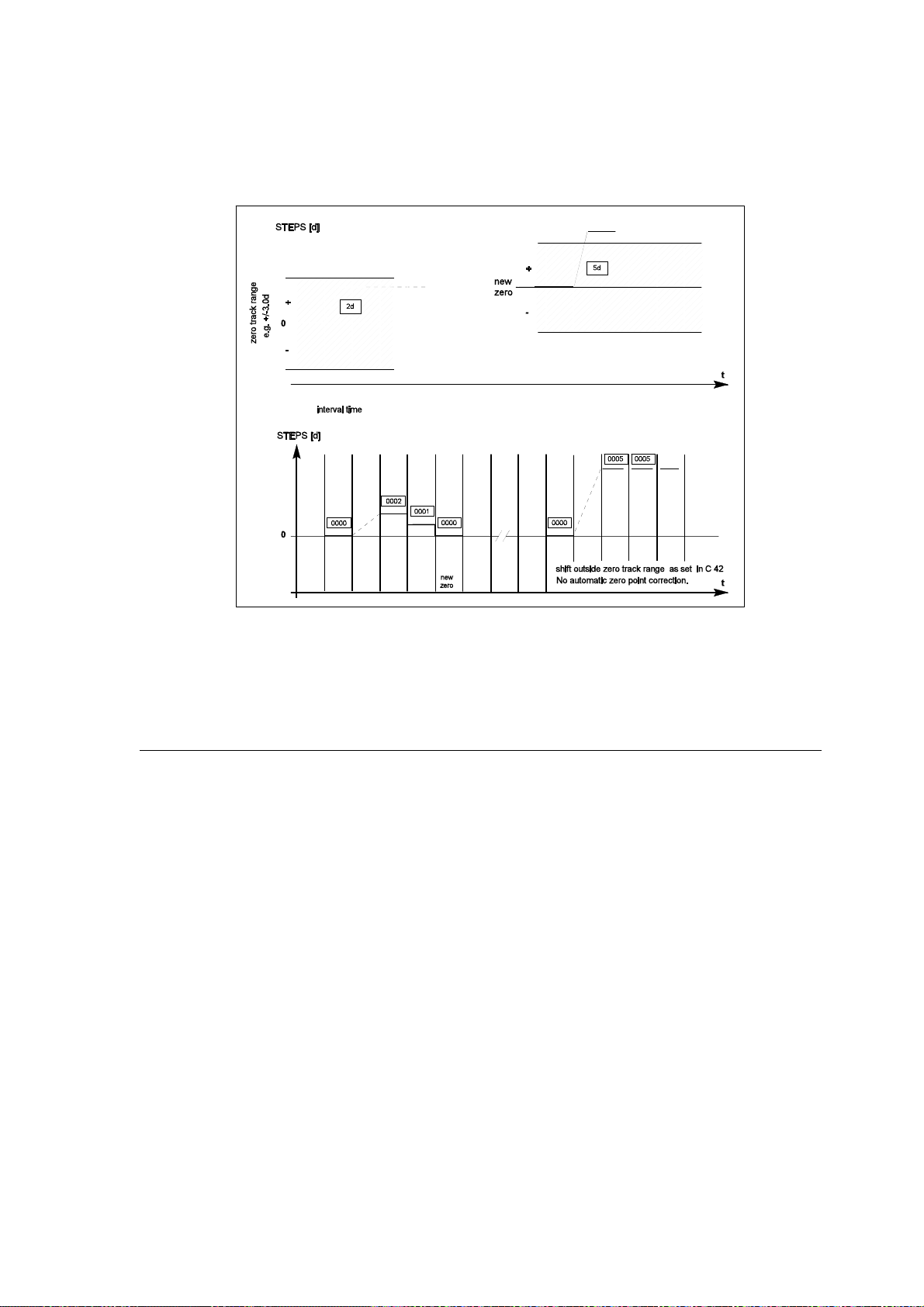
OPERATING MANUAL PR 1612/02, Rel. $$ 2.30 Page: 6 - 28
Example: Zero tracking has to be performed within set interval time.
Settings: Automatic zero tracking range (C43) = 3,0 d
Step width of automatic zero tracking (C44) = 1,0 d
Interval time (C45) = 0 1 = 1x 0.3 sec
Parameter Function/Description Default value
C 46 .. 50 ° Analog Test
The test value defined here will be stored in the EEPROM and
can be used for instrument function checking, if necessary.
Therefore, it should be noted or printed out via C58 like the
other parameter data.
C 46 ° Test mode 0 (f.s.d.)
The test value for the analog test is valid for the f.s.d.
The gain factor for its display is stored during calibration.
Two different test values are adjustable.
0 = display of an absolute test value.
No error = display of f.s.d.
1 = display of difference between the stored f.s.d. value
and the actual test value.
No error = display of 00000.
C 47 ° Test switch function 0 (as C46)
Definition of test switch function mode, whereby 2 modes
are selectable:
0 = when pressing key -TEST-, the test preselected below
TEST MODE will be activated.
1 = when pressing key -TEST-, an EEPROM checksum is
displayed.

OPERATING MANUAL PR 1612/02, Rel. $$ 2.30 Page: 6 - 29
Parameter Function/Description Default value
C 48 ° Test value tolerance 01 (1 d)
Definition of an acceptable difference of 01 .. 15 d between
the stored f.s.d. value and the actual test display.
The TEST VALUE TOLERANCE is required for an automatic
TEST REPETITION (C49).
With out of tolerance, the weight display of
the indicator will be switched off automatically and an error
message is generated.
C 49 ° Test repetition time 00 ( 0 hours)
Definition of a repetition time of 1 to 24 hours within which an
automatic test shall be repeated.
With a setting to 00 hours, the test must be activated manually
by pressing key -TEST- .
C 50 ° Test value generation actual value
The test mode is switched on, and a test value
corresponding to the f.s.d. value will be generated and stored.
C 51 ° Min. weight limit for a print-out 50 (50 d)
Dependent of local calibration regulations, transmission
of printer data can be disabled as long as the gross weight
is between zero and the adjusted value up to 99 d.
00 = no disabling.
C52 ° Multi-range scale 00000 (none)
Definition of a switch-over point for a multi-range scale.
Above the switch-over point, i.e. in the upper part of the scale,
a lower resolution (next higher step width ) is used.
This is marked by two vertical dashes in front of the uppermost
decade (Il). With the weight below the switch-over point, the
higher step width remains unchanged.
As soon as the weight is within the zero setting range (marked by
one vertical dash in front of the uppermost decade (I), the initial
step width can be switched on again by pressing key ->0<-.
With the weight accurately at zero (within the ± 1/4 d range),
the initial step width will be switched on automatically, provided
the display is in "standstill" and the instrument is not tared.
Mode '10 times higher resolution' (see C36) can be used as long as
scale end value / lowest step width
Example 1: Example 2:
range 1 = 30 t, e1 = 10 kg (3000d) range 1 = 600 kg, e1 = 0.2 kg (3000d)
range 2 = 60 t, e2 = 20 kg (3000d) range 2 = 1500 kg, e2 = 0.5 kg (3000d)
60 t / 10 kg = 6000 d = ok 1500 kg / 0.2 kg = 7500 d = not ok
The following table shows all conditions of a multi range scale, taking also into
account a possible net mode as to be set in parameter C59.
# 6000 d.

OPERATING MANUAL PR 1612/02, Rel. $$ 2.30 Page: 6 - 30
Parameter Function/Description Default value
C 53 ° Communication mode on/off 0 (off)
0 = off, 1 = EW-protocol on
For other than EW protocols, see part 8.2.
Note:
The communication mode can only be driven via the interface in line
1/A .
With the communication mode activated, and if not selected
otherwise, configuration 5 in C10 will automatically be switched
on.
With communication mode off, configuration 1 in C10 will be
switched on automatically, if not selected otherwise!
C 54 ° Instrument address A
Definition of an address between A .. Z of the PR 1612/02 for
the communication mode.

OPERATING MANUAL PR 1612/02, Rel. $$ 2.30 Page: 6 - 31
Parameter Function/Description Default value
C 55 ° Weights & Measures mode on/off YES (on)
YES = on, no = off
1. W&M mode on and negative gross weight:
Weight display incl. negative sign dimmed, dimension sign off.
No data transmission to remote display and/or printer.
2. W&M mode on and negative net weight:
Weight display incl. negative sign bright, dimension sign on.
Data transmission to remote display and/or printer.
Print-out e.g.: <wwww.w kg> N
3. W&M mode off and negative gross weight:
Same as mentioned below 1.
4. W&M mode off and negative net weight:
Same as mentioned below 2., but
print-out e.g.: wwww.w kg N
C 56 without function
C 57 ° Analog filter on/off 1 (on)
0 = filter off, 1 = filter on.
Switching the filter on or off must already be done when
starting the calibration process (see C30).
C 58 Parameter data print-out
Note !!
The parameter data must be printed out after calibration and
the print-out must be kept safely for a possible service case.
Print-out is possible only via an interface in line 1 / A and with
parameter C10 set to 1.
For print-out example of the default values please refer to part 6.7
C 59 ° Multi-range scale in gross/net weight display mode 0 (off)
0 = off = no change with reference to C52.
1 = when tared, the weight display switches over to the
smaller step width, or higher resolution (indication of I ).
As soon as exceeding the value as adjusted in C52
the weight display switches over to
the higher step width, or lower resolution (indication of II ).
With the weight falling below the switchover point,
the higher step width remains unchanged until
conditions as indicated in the table at C52 are
reached.
C 80 Display of consumed zero set range 00000
Display of that part of the zero set range adjusted in C42,
which is consumed (suppressed) already by having pressed
key ->0<-.

OPERATING MANUAL PR 1612/02, Rel. $$ 2.30 Page: 6 - 32
Parameter Function/Description Default value
C 82 Display of "board" number different, e.g.
Needed for e.g. 0492083
- ordering SW option PR 1613/05,
or
- resetting an entered SW licence number.
In order to reset, the displayed board number has to be
entered in C83.
C 83 ° Entry of licence number(s) 0000000
The valid licence number for SW option PR 1613/05
must be entered.
When entering a wrong licence number CErr 9 will be displayed.
In this case
- press key NEXT STEP,
- after the display of 0000000 press key EXIT = B,
- enter the correct licence number, or
- skip and change into next desired parameter !
If enabled by a correct licence number the used SW option
will be displayed also after performing a 'WARM' start (see
also part 5.5.1).
C84 Reset of licence number no
In order to enable temporary licence numbers in C83,
select YES, and confirm by pressing key NEXT STEP.
Due to this, an enabled regular
will be reset temporary till the next warm start.
C85 not used
C86 without function no
C90 .. 95 without function
C96 Test figure for factory internal use different, e.g.
Without importance for operation. 8141
After display of fail , the program jumps to
parameter C99.
C99 Display of instrument type (PR 1612/02), embedded SW version,
and all enabled SW options
Subsequently the program jumps automatically to parameter C00.
licence number for PR 1613/05
Note:
If calibration is finished now, and no further settings of other parameters are required any
more, store (save) data as described in the following part 6.6.

OPERATING MANUAL PR 1612/02, Rel. $$ 2.30 Page: 6 - 33
6.6 PROTECTING/STORAGE OF ENTERED CALIBRATION DATA IN EEPROM
Switch CAL is in position C
Leave the set-up mode by pressing key EXIT (B)
During approx. 2 seconds, the display shows:
Then it changes to: ( no
By means of key change to yes ( yes
(when no, no storage of data)
press key NEXT STEP
Display shows for 3 seconds:
Move switch CAL to position: ¯c
store ?
all dat

OPERATING MANUAL PR 1612/02, Rel. $$ 2.30 Page: 6 - 34
6.7 S E T - U P L I S T
INSTRUMENT: PR 1612/02
FACTORY-NR.: LO
After setting the instruments, all calibration and configuration data as mentioned at the
overleaf are to be noted, unless they have been printed-out via parameter C58.
Moreover also the conditions as listed below have to be noted.
As data can be lost in case of defects or failures of the indicator, this list has to be kept
carefully for possibly arising service actions.
FUNCTION FACTORY INSERTED / ADJUSTED
Mains voltage 220 V
Software-version 2.3
INTERFACE FACTORY INSERTED / ADJUSTED
Line 1/A none
Line 2/B none
Paralellport none
SWITCH FACTORY ADJUSTED
CAL C
MODE C
BAT open
12/20 V 12 V
FURTHER INFORMATION:
DATE OF COMMISSIONING: SIGN:

OPERATING MANUAL PR 1612/02, Rel. $$ 2.30 Page: 6 - 35
PARAM DEFAULT SETTINGS PARAM. DEFAULT SETTINGS
C 01 Year, Date, C 40 1
C 02 without function C 41 1
C 03 without function C 42 0060
C 04 4800bd C 43 0,0
C 05 0 C 44 0,0
C 06 0 C 45 01
C 07 without function C 46 0
C 08 without function C 47 0
C 09 without function C 48 01
C 10 01 C 49 00
C 11 unused C 50 act. test value
C 12 0 C 51 50
C 13 for SW-option PR 1613/05 only ! C 52 00000
C 14 0 C 53 0
C 15 41000 C 54 A
C 16 000000 C 55 YES
C 17 0 C 56 without function
C 18 4 C 57 1
C 19 0003 C 58 print-out
C 20 0 C 59 0
C 21 0000 C 60..73 unused
C 22 A C 80 display of used zero set range
C 23 unused C 81 unused
C 24 0000 C 82 display of board number
C 25 00000 C 83 entry of license number
C 26 00000 C 84 no
C 27 00000 C 85/86 without function
C 28 00000 C 87..89 unused
C 29 H00, A=0 C 90..95 without function
C 30 0 C 96 test value for factory-internal test
C 31 0 C 97/98 unused
C 32 0001 C 99 display of used software
C 33 0009
C 34 03
C 35 03000 / 12
C 36 act. test value
C 37 act. weight
C 38 12 / 0.0000
C 39 03000/12/1.000

OPERATING MANUAL PR 1612/02, Rel. $$ 2.30 Page: 6 - 36
6.7.1 Print-out example of the default values:
PR1612/02-2.34.3
DATE: 27.11.1996 21:46
------------------------BOARDNR.: NO DAT
SOFTWAREOPTION: NOT ENABLED
HARDWAREOPTION:
BAUDRATE LINE 1: 4800 BD
XON/XOFF SYNC. : NO
DATA BIT : 7 ,EVEN PARITY
I/O CONFIGURATION: 01
COMMUNICATION: OFF
SLAVE ADDRESS: "A"
S5-ADDRESS: 00000
REMOTE DISPLAY: OFF
PRINTER PROTOCOLL ON #T: NO
PRINTER CONF. C15: 41000
SEQUENCE NR. C16: 00000
ANALOG-OUTPUT: 00
BCD/ANALOG-OUTPUT: GROSS
WEIGHT
DISABLE KEYBOARD: NO
DECIMAL POINT: 0
DIMENSION: "kg"
STEPWIDTH: 1 kg
OVERLOAD: 0009 d
MEASURING TIME :0.300 s
MAX. : 3000 kg
SUPPLY: 12 VOLT
DEADLOAD: 0.0000 mV/V
SPAN: 1.0000 mV/V
STANDSTILL RANGE : 01 d
STANDSTILL TIME : 01 M
ZERO RANGE : 0060 d
AUTOZERO TRACK RANGE: 0.0 d
CORRECTION VALUE: 0.0 d
TIME INTERVAL: 01 M
CHECK MODE : 0
TESTKEY FUNCTION :0
CHECK TOLERANCE : 01 d
REPEAT CHECK IN :00 h
CHECKNUMBER : 00000
DON'T PRINT BELOW: 50 d
RESTART-MODE: 4
CALMING TIME: 00003 sec
PROTECTION NUMBER 1: OFF
> LIMIT 1, ON: 0 kg
> LIMIT 1, OFF: 0 kg
< LIMIT 2, ON: 0 kg
< LIMIT 2, OFF: 0 kg
MULTI INTERVALL: NO
CHANGE STEP AT: 0 kg
CHANGE STEP AT: 0 kg
W & M - MODE: YES
ANALOG-FILTER: ON
-------------------------

OPERATING MANUAL PR 1612/02, Rel. $$ 2.30 Page: 7 - 0a
CONTENTS OF PART 7 Page
7.1 EXTERNAL LOADCELL SUPPLY 7-1
7.2 EX-APPLICATION (PR 1612/02 - PR 1625/PR 1626) 7-2
7.3 CONNECTION OF REMOTE DISPLAYS 7-3
7.3.1 PR 1612/02 with PR 1627/00 7-3
7.3.1.1 Application example 7-3
7.3.1.2 Connection via modules PR 1601, PR 1602, or
PR 1604 7-4
7.3.2 PR 1612/02 with PR 1577/00 7-5
7.3.2.1 Application example 7-5
7.4 CONNECTION OF A PRINTER DEVICE 7-6
7.4.1 Application example with PR 1602 7-6
7.5 SERIAL INPUT AND OUTPUT MODULES 7-7
7.6 OPTION PR1601 (20mA current loop module) 7-7
7.6.1 Technical data 7-7
7.6.2 Description/Application 7-7
7.6.2.1 Typical application example with PR 1601:
PR 1612/02 with 3 PR 1627/00 7-9
7.7 OPTION PR 1602 (RS232 module) 7-10
7.7.1 Technical data 7-10
7.7.2 Description/Application 7-10
7.7.2.1 Typical application example with PR 1602:
PR 1612/02 with PC 7-11
7.8 OPTION PR 1604 (RS422/485 module) 7-12
7.8.1 Technical data 7-12
7.8.2 Installation 7-12
7.8.3 Description 7-12
7.8.4 Settings 7-13
7.8.5 Application examples 7-14
7.8.5.1 RS 422 Master/Slave point to point connection 7-14
7.8.5.2 RS 485 2-wire point to point connection 7-14
7.8.5.3 RS485 Master/Slave multi-point connection 7-15
7.9 OPTION PR 1606 (analog output module) 7-16
7.9.1 Technical data 7-16
7.9.2 Installation 7-16
7.9.3 Description/Application 7-16
7.10 OPTION PR 160800 (BCD/PLC output module with common supply) 7-17
7.10.1 Technical data 7-17
7.10.2 Installation 7-17
7.10.3 Settings 7-17
7.10.4 Application 7-18
7.10.4.1 Output mode 1 7-18
7.10.4.2 Output mode 2 7-19
7.10.4.3 Output mode 3 7-19

OPERATING MANUAL PR 1612/02, Rel. $$ 2.30 Page: 7 - 0b
7.10.4.4 General connection examples 7-20
7.10.4.5 Pin allocation of the PR 1608/00 connection cable 7-20
7.10.4.6 Typical connection example to a PLC 7-21
7.11 OPTION PR 1608/10 (BCD/PLC output module with common ground) 7-22
7.11.1 Technical data 7-22
7.11.2 Installation 7-22
7.11.3 Settings 7-22
7.11.4 Application 7-23
7.11.4.1 Output mode 1 7-23
7.11.4.2 Output mode 2 7-24
7.11.4.3 Output mode 3 7-24
7.11.4.4 General connection examples 7-25
7.11.4.5 Typical connection example to a PLC 7-25
7.11.4.6 Pin allocation of the PR 1608/00 connection cable 7-26
7.12 LOCATION OF SEALS (sealing plan) 7-27
7.12.1 Official calibration procedure acc. to EC-directive 90/384/EEC 7-29

OPERATING MANUAL PR 1612/02, Rel. $$ 2.30 Page: 7 - 1
7.1 EXTERNAL LOADCELL SUPPLY (example)
** Applicable power supply units (for non-assized use) :
for ± 6 V supply e. g. 2 x type EWS-15-6 } of company "LAMBDA"
for ± 10 V supply e. g. 2 x type EWS-15-9 } connected in serie
or alternatively
for ± 6 V supply e. g. 1 x Typ PSK 205 } of company
for ± 10 V supply e. g. 1 x Typ PSK 212 } "SCHROFF"
The PR 1613 must be adjusted as described in the Operating Manual.

OPERATING MANUAL PR 1612/02, Rel. $$ 2.30 Page: 7 - 2
7.2 EX-APPLICATION (example)

OPERATING MANUAL PR 1612/02, Rel. $$ 2.30 Page: 7 - 3
7.3 CONNECTION OF REMOTE DISPLAYS
Upon delivery remote display units can be connected to the PR 1612/02 only via its serial
interface at line 2 (B) by using interface modules PR 1601 (20 mA current loop TX/RX), or
PR 1602 (RS232), or PR 1604 (RS422/485).
Above mentioned modules are to be set by means of their solder links, and as described
below.
Respective settings at the PR 1612/02 for a display mode have to be made in parameters C07,
(C08), C10, and C14.
The data transmission between indicator and remote display unit(s) runs as described in part
8.4, and will be started only after having left the set-up procedure.
The connection has to be performed via the 9-pole connector and as shown below.
7.3.1 PR 1612/02 with PR 1627/00
7.3.1.1 Application example

OPERATING MANUAL PR 1612/02, Rel. $$ 2.30 Page: 7 - 4
7.3.1.2 Connection via modules PR 1601, PR 1602, or PR 1604
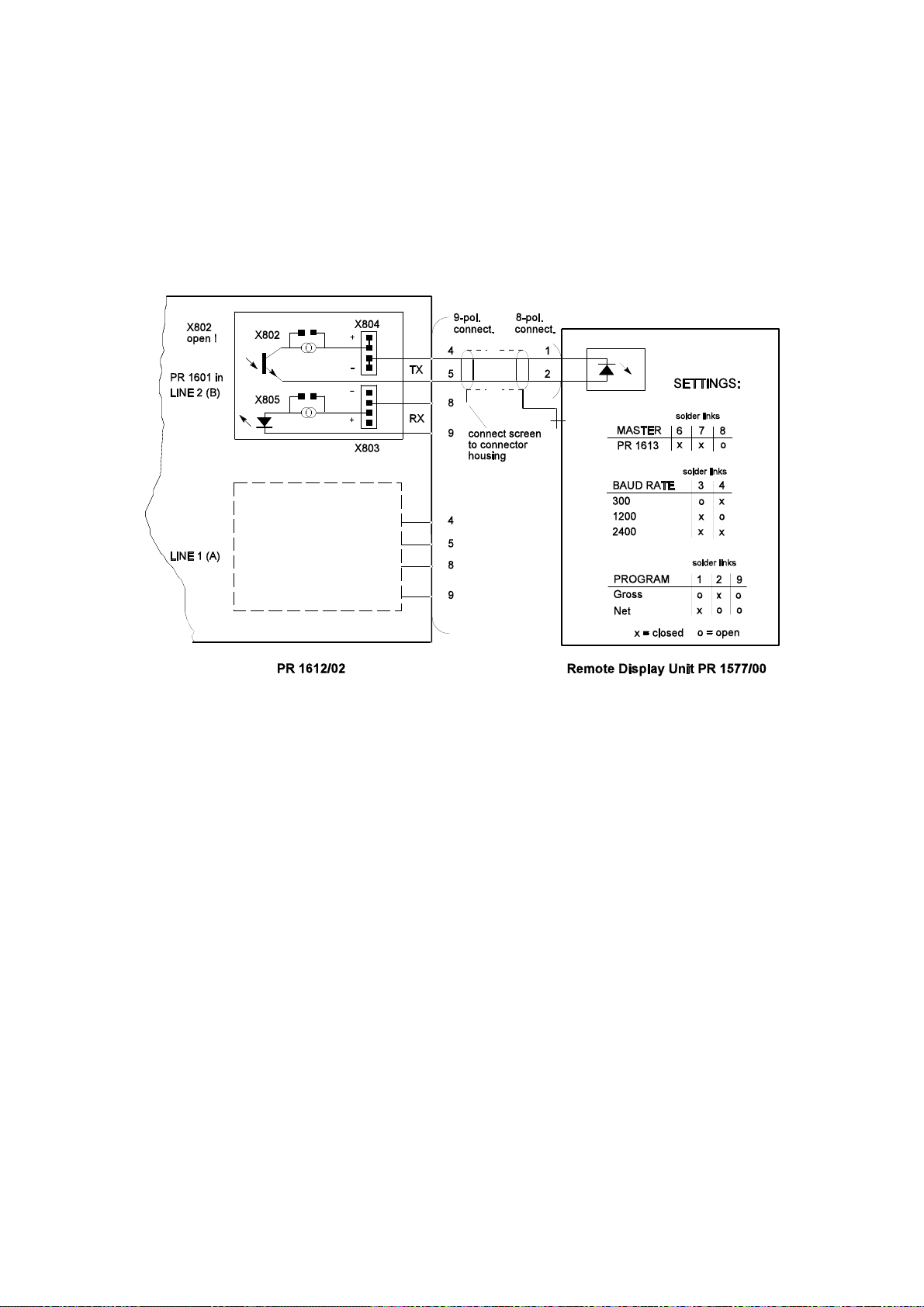
OPERATING MANUAL PR 1612/02, Rel. $$ 2.30 Page: 7 - 5
7.3.2 PR 1612/02 with PR 1577/00
7.3.2.1 Application example
Note:
Remote display units are connectable to the PR 1612/02 only via its interface in line 2(B).
Required settings at the PR 1612/02:
1. baudrate (parameter C04) = 300, 600, 1200, or 2400 b/s
2. XON/XOFF (parameter C05) = 0 = off
3. bit and parity (parameter C06) = 0 = 7 / even
3. serial i/o configuration (parameter C10) = 1
4. remote display mode (parameter C14) = 1 = PR 1577-mode 'on'

OPERATING MANUAL PR 1612/02, Rel. $$ 2.30 Page: 7 - 6
7.4 CONNECTION OF A PRINTER DEVICE
A printer device can be connected to the PR 1612/02 via the 9-pole connector at the rear
of the indicator and as drawn below.
Corresponding settings have to be performed in parameters C10, C15, and possibly C20.
Following connections are possible:
1 printer via line 1(A) without hand shake mode, or
1 printer via line 2(B) with hand shake mode, or
1 remote display unit via line 2(B), or
1 instrument in communication mode via line 1(A).
The data transmission between indicator and printer device runs as described in part 8.3, and
can be started only after having left the set-up procedure.
The following interface modules can be used:
PR 1601 (20 mA current loop TX/RX), or
PR 1602 (RS232), or
PR 1604 (RS422/485).
7.4.1 Application example with PR 1602
* Do not connect !
• • Handshake mode only possible from printer to PR 1612/02 and via line 2(B).
Solder link X802 closed = handshake mode off,
X802 open = handshake mode on.
Solder link X803 will not be controlled by the PR 1612/02 software.

OPERATING MANUAL PR 1612/02, Rel. $$ 2.30 Page: 7 - 7
7.5 SERIAL INPUT AND OUTPUT MODULES
The serial l/O-modules PR 1601, PR 1602, or PR 1604 have to be inserted into the sockets of
interface lines 1(A) and/or 2(B) onto the main PCB of the PR 1612/02 indicator depending on
conditions as mentioned below (see also parts 7.2 .. 7.4).
Mode PR 1601 PR 1602 PR 1604
--------------------------------------------------------------------------communication 1(A) 1(A) 1(A)
or
remote display 2(B) 2(B) 2(B)
or
printer 1(A), 2(B) 1(A), 2(B) 1(A), 2(B)
Above mentioned serial I/O modules
are to be connected via the 9-pole
connector at the rear of the indicator
and as desribed in the following
parts.
Caution !
Sockets 1(A) and 2(B)
are connected in parallel.
Therefore only one interface module
can be used at the same time.
Before installing the interface
modules the PR 1612/02 must be
switched off.
7.6 OPTION PR 1601 (20 mA current loop module)
7.6.1 Technical data
Refer to part 3.8
7.6.2 Description / Application
The PR 1601 is an optodecoupled bidirectional serial communication interface module for data
transfer via 20 ma current loops (transmission loop and receiving loop) .
Transmitter, receiver and their reference potential are galvanically separated from the
electronics of the PR 1612/02 by means of optocouplers and a separate winding of the mains
transformer.
By means of solder links X804 and X 803 on the PR 1601 module its output and input can be
set for active or passive mode.
In active mode the corresponding loop is supplied by a PR 1612/02 internal galvanically
isolated voltage, whilst in passive mode the loop must be supplied by an external power supply
unit of 12 to 31 V DC (e.g. of type PR 1624/00 from Philips) .
The interface module has got a 20 mA constant current regulator each in the receiving and in
the transmission loop.

OPERATING MANUAL PR 1612/02, Rel. $$ 2.30 Page: 7 - 8
Note:
In case of several devices per loop only one current regulator per loop should be active.
In order to avoid malfunctions all non required regulators per loop and per PR 1601 have to be
switched off by closing solder link X802 for the transmission loop, and X805 for the receiving
loop.
Nevertheless the number of devices per loop is limited and can be calculated by:
Supply voltage of loop - voltage drop via external devices
n = -------------------------------------------------------------------------------
max
whe reby 4 V is the voltage drop across the transmission or receiving input of the PR 1601
module inserted at the PR 1612/02 with solder links X802 and X805 opened.
The PR 1612/02-internal supply voltage is 8V, i.e. only one remote display unit can be
connected in this case.
As only one current regulator per loop is required, all the other ones can be disabled by closing
their solder links X802 and X805.
The maximum baud rate using a PR 1601 in a PR 1612/02 is 4800b/s.
As i nterconnection cable to connected devices a screened and pairwisely twisted cable like
type LifYCY 2 x 2 x 0,5mm² of company METROFUNK can be used. Maximum cable length is
1000 meter.
4V
Solder link Function
-------------------------------------------X 802 current regulator for
TX-loop on/off.
X 803 RX-loop supplied
internal (a closed),
external (p closed).
X 804 TX-loop supplied
internal (a closed),
external (p closed).
X 805 current regulator for
RX-loop on/off.
X 806 TX-loop can be
short circuited by
relay contact in case of
power off.
X 807 supply of relay on/off.

OPERATING MANUAL PR 1612/02, Rel. $$ 2.30 Page: 7 - 9
7.6.2.1 Typical application example with PR 1601
(PR 1612/02 with 3 PR 1627/00 remote display units)
Note:
In this example module PR 1601 of the
PR 1612/02 is set for a PR 1612/02internal supply of the current loops
(link a of X803 and X804 closed).
Modules PR 1601 of the PR 1627/00 are
set for an external supply (link p of X803
and X804 closed).
The loops will therewith be supplied by
the PR 1612/02.
As only one current regulator per loop
may be active, the current regulators
at the PR 1601of the PR 1612/02 are
enabled (X802 and X805 open),
and the ones at the PR 1601 of the
PR 1627/00 disabled (X802 and X805
closed).
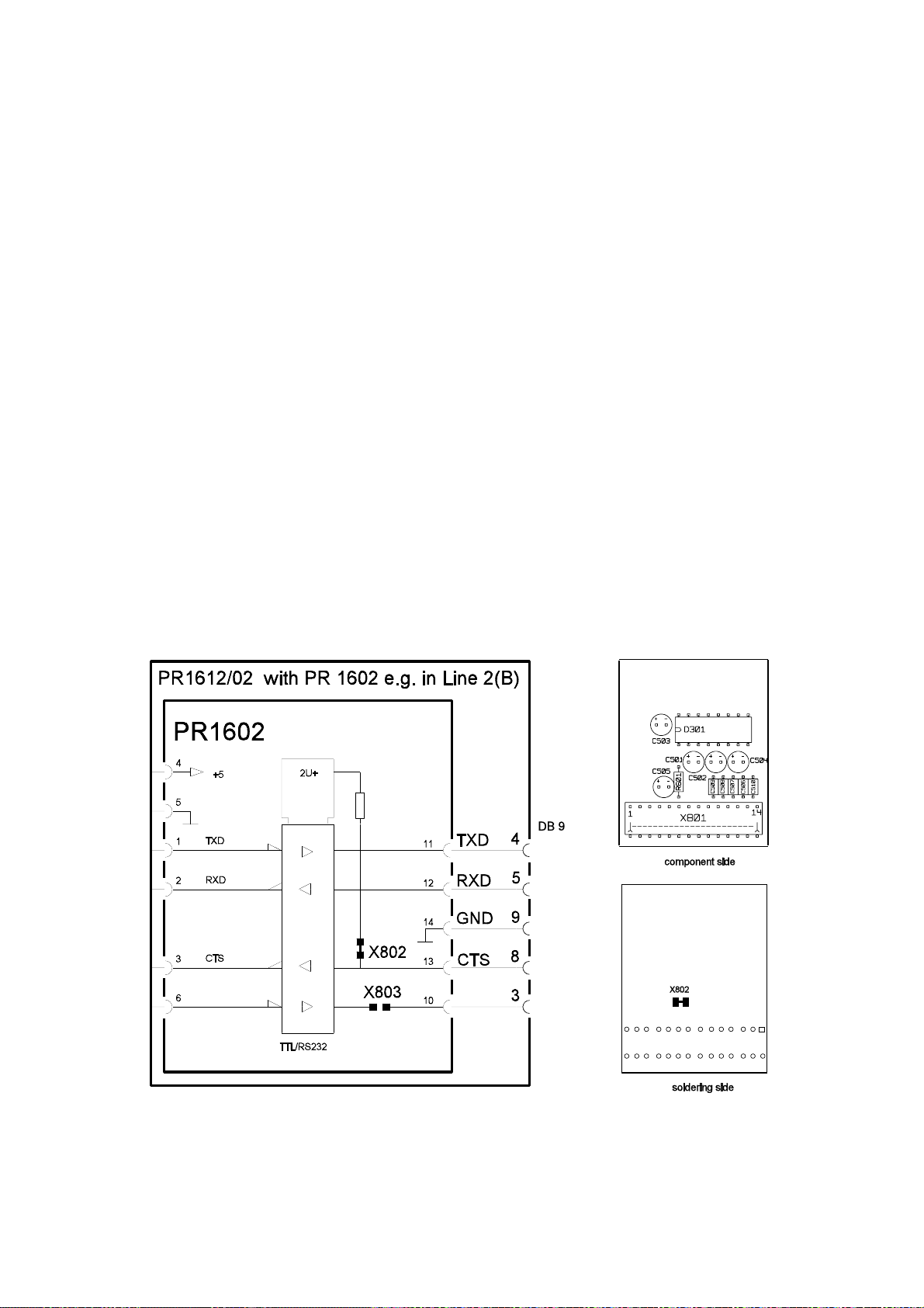
OPERATING MANUAL PR 1612/02, Rel. $$ 2.30 Page: 7 - 10
7.7 OPTION PR 1602 (RS 232 module)
7.7.1 Technical data
Refer to part 3.8
7.7.2 Description / Application
The PR 1602 is a bidirectional serial communication interface module for a data transfer
according to the EIA RS 232C, or CCITT V.24 standard.
The data transfer is possible via inputs/outputs TXD, RXD. CTS (clear to send) serve for
corresponding control.
Output and inputs are not galvanically isolated from the inner electronics of the PR 1612/02.
As interconnection cable to connected devices a screened and pairwisely twisted cable like
type LifYCY 2 x 2 x 0.5mm² of company METROFUNK can be used.
Maximum cable length is 15 meters.
The maximum baud rate using a PR 1602 is 9600 b/s.
Typical application examples are shown in part 7.4., and in the following.
Solder link Function
--------------------------------------------------------------------------------X802 open control by external CTS signal possible
X802 closed CTS continuously (internal) enabled
X803 will not be controlled by PR 1612/02 software
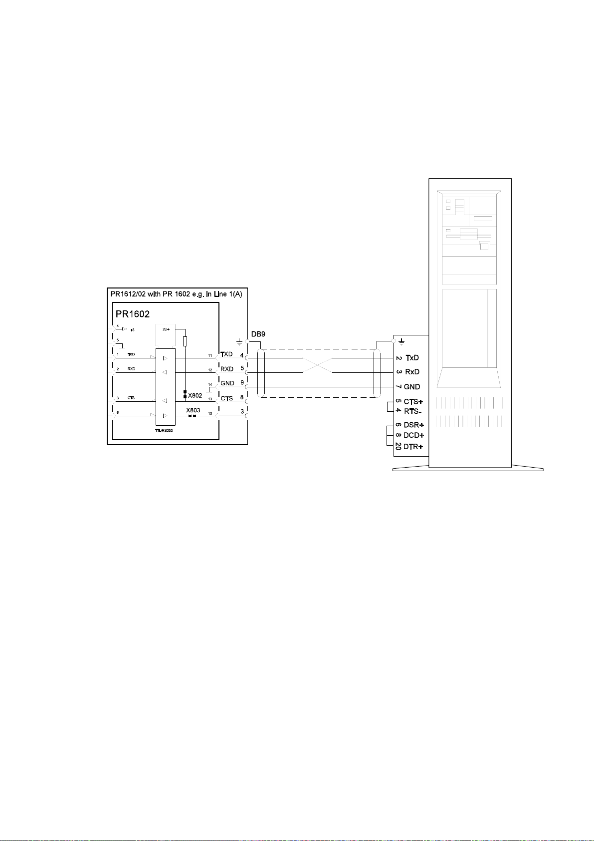
OPERATING MANUAL PR 1612/02, Rel. $$ 2.30 Page: 7 - 11
7.7.2.1 Typical application example with PR 1602:
(PR 1612/02 connected to a PC)
Note:
A communication between PR 1612/02 and super or subordinate systems is possible only
via line1(A) of the PR 1612/02.
Required settings at the PR 1612/02:
1. baudrate (parameter C05) = 300 ... 9600 b/s
2. bit and parity (parameter C06) = 0 = 7 / even
3. serial i/o configuration (parameter C10) = 3
4. communication mode (parameter C53) = 1 (for EW-protocol)
5. address of the PR 1612/02 (parameter C54) = A .. Z
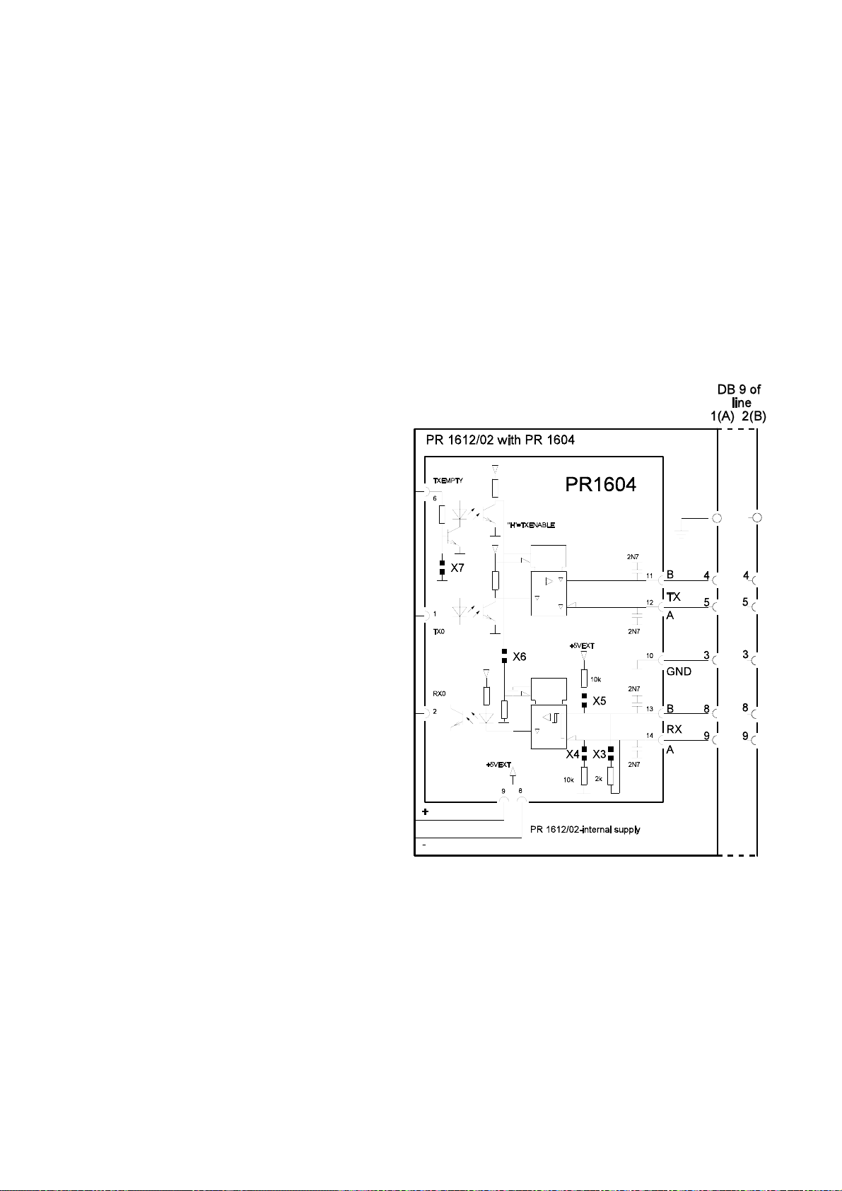
OPERATING MANUAL PR 1612/02, Rel. $$ 2.30 Page: 7 - 12
7.8 OPTION PR 1604 (RS 422/485 module)
7.8.1 Technical data
Refer to part 3.8
7.8.2 Installation
Refer to part 7.5
7.8.3 Description
The interface module PR 1604
permits the communication via a
bus sytem which works according
to the EIA RS 422, or the RS 485
standard.
RS 422 enables a communication
between only two devices
(point-to-point) in full duplex mode,
i.e. via a 4-wire connection.
RS485 enables a communication
between
two devices (point-to-point)
in full duplex mode via 4-wire
connection ,
or in half duplex mode via 2-wire
connection,
or between several devices via a
bus connection.
Transmitter, receiver and
reference potential are galvanically isolated from the inner
electronics of the PR 1612/02 by
separate tranformer winding
and optodecouplers.
As interconnection cable use
a 3 - pair cable, pairwisely twisted and totally screened cable like type LifYCY 3x2x0.5mm².
One pair can be used for the common ground.
solder-links drawn as set upon delivery
The bus cable has to be taken as closely as possible to the particular instruments in order to
keep the connection to the indicator (branch cable) as short as possible.
This connection between bus cable and indicator (branch cable) has to be made of the
same kind of cable as the bus cable.
Maximum cable length is 1000 meters.
The maximum baud rate using a PR 1604 into a PR 1612/02 is 9600 b/s.

OPERATING MANUAL PR 1612/02, Rel. $$ 2.30 Page: 7 - 13
7.8.4 Settings
Solder link Function
---------------------------------------------------------------------------------------------------------------X3 } closed } internal bus terminating resistors:
X4 } closed } bus by 205
X5 } closed } supply voltage by 2 x 1k54 k
X6 open RX continuously enabled
X6 closed RX inhibited when TX enabled by PR 1612/02-internal control
X7 open TX in tristate by PR 1612/02-internal control
PR 1604
status point to point bus point to point bus
master RS 485
X3, X4, X5, X6
slave RS 485
X6
other
slaves
two-wire system four-wire system
RS 485
X3, X4, X5, X6
RS 485
X6
S (X3),
S (X4/5).
RS 422
X3, X7
RS 422
X3, X7
RS 485
X3, X4, X5
RS 485
none
last
slave
RS 485
X6
Note: above mentioned solder-links have to be closed
RS 485
X3, X4, X5

OPERATING MANUAL PR 1612/02, Rel. $$ 2.30 Page: 7 - 14
7.8.5 Applications
7.8.5.1 RS 422 Master/Slave point to point connection (example)
Connection of the PR 1612/02/.. (slave) with an external device (master) which consists of a
RS422 interface. The receiver of the external device must be terminated properly !
Settings at the PR 1604: solder links X3, X7 closed, solder links X4, X5, X6 open
7.8.5.2 RS 485 2-wire point to point connection (example)
Connection of the PR 1612/02/.. with an external device (PLC) by means of e.g. MODBUS
or JBUS in half-duplex mode. The respective devices can only communicate via a 2-wire
connection. The receiver of the external device must be terminated properly !
Settings at the PR 1604: solder links X3, X4, X5, X6 closed, solder link X7 open
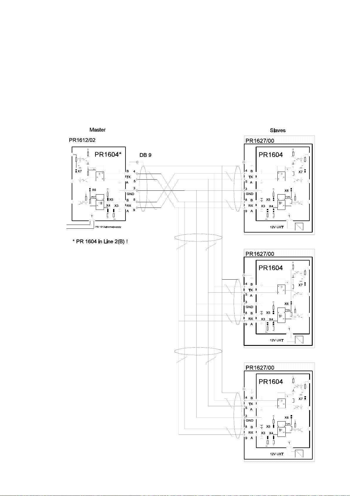
OPERATING MANUAL PR 1612/02, Rel. $$ 2.30 Page: 7 - 15
7.8.5.3 RS 485 Master/Slave multi-point connection (example)
Connection of a PR 1612/02/.. with three PR 1627/00-remote display units.
The PR 1612/02 function as Master in this case, and the three remote display units as
slaves.
Settings at the PR 1604:
Solder links X3, X4, X5 closed
X6, X7 open
Note:
Acc. to the standards, it is recommended to terminate only the last
PR 1604 of the bus system by
closing its solder links X3, X4,
and X5.

OPERATING MANUAL PR 1612/02, Rel. $$ 2.30 Page: 7 - 16
7.9 OPTION PR 1606 (analog output module)
7.9.1 Technical data
Refer to part 3.10
7.9.2 Installation
Befo re inst alling disconnect the mains voltage from the PR 1612/02 and cut the flat cable
behind the first connector.
7.9.3 Description / Application
The PR 1606 converts the binary value of
the PR 1612/02 into a respective analogue
value.
The kind of value (gross, net, etc)
can be defined by means of parameter C12
during configuration (refer to part 6.3.1, C12).
Upon delivery the instrument delivers
0 .. +10V DC, and
0 .. +20 mA
(both end values at f.s.d.).
By means of parameter C17
the offset can be set to
2 .. +10V DC, and
4 .. +20mA
during configuration (refer to part 6.3.1, C17).
Note:
When using the PR 1606:
- only an output signal of positive weight values will be generated,
- if the gross we i g h t i s > f.s.d. + Amax , o r w ith the indication of ERR1, 2, 3, or 6, the last valid
output signal will be kept, until the value falls below a. m. limits again.
- if the gross w eight is < ¼ d, or with the indic ation of ERR4, 5, or 7, the output signal remains
at 'zero' level signal as selected by C17, until < ¼ d will be exceeded again.
- after taring in output mode 1 and 3 (weight display and output signal = net) the output signal
will be kept at 'zero' level, if the net weight becomes negative.
 Loading...