

Philips PMLL5226B, PMLL5227B, PMLL5228B, PMLL5229B, PMLL5231B Datasheet
...
DISCRETE SEMICONDUCTORS
DATA SH EET
1/3 page (Datasheet)
M3D054
PMLL5225B to PMLL5267B
Voltage regulator diodes
Product specification
Supersedes data of November 1993
1996 Apr 26
Philips Semiconductors Product specification
Voltage regulator diodes PMLL5225B to PMLL5267B
FEATURES
• Total power dissipation:
max. 500 mW
• Tolerance series: ±5%
DESCRIPTION
Low-power voltage regulator diodes in small hermetically sealed glass
SOD80C SMD packages. The series consists of 43 types with nominal working
voltages from 3.0 to 75 V.
• Working voltage range:
nom. 3.0 to 75 V
• Non-repetitive peak reverse power
dissipation: max. 40 W.
APPLICATIONS
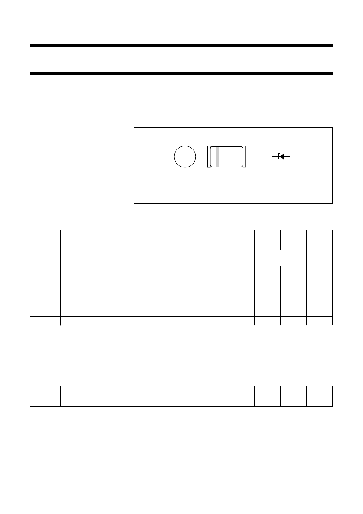
handbook, 4 columns
ka
MAM215
• Low-power voltage stabilizers or
voltage references.
The cathode is indicated by a yellow band.
Fig.1 Simplified outline (SOD80C) and symbol.
LIMITING VALUES
In accordance with the Absolute Maximum Rating System (IEC 134).
SYMBOL PARAMETER CONDITIONS MIN. MAX. UNIT
I
F
I
ZSM
P
P
tot
ZSM
continuous forward current − 250 mA
non-repetitive peak reverse current tp= 100 µs; square wave;
Tj=25°C prior to surge
total power dissipation T
non-repetitive peak reverse power
dissipation
=25°C; note 1 − 500 mW
amb
tp= 100 µs; square wave;
Tj=25°C prior to surge; see Fig.3
= 8.3 ms; square wave;
t
p
see Table
“Per type”
− 40 W
− 10 W
Tj≤ 55 °C prior to surge
T
stg
T
j
storage temperature −65 +200 °C
junction temperature −65 +200 °C
Note
1. If flanges are kept at T
flange
≤ 75 °C.
ELECTRICAL CHARACTERISTICS
Total series
=25°C; unless otherwise specified.
T
j
SYMBOL PARAMETER CONDITIONS MIN. MAX. UNIT
V
F
forward voltage IF= 200 mA; see Fig.4 − 1.1 V
1996 Apr 26 2

1996 Apr 26 3
Per type
=25°C; unless otherwise specified.
T
j
Philips Semiconductors Product specification
Voltage regulator diodes PMLL5225B to PMLL5267B
TYPE No.
WORKING
VOLTAGE
(1)
(V)
V
Z
at I
Ztest
DIFFERENTIAL
RESISTANCE
(Ω)
r
dif
at I
Ztest
TEMP. COEFF.
(%/K)
S
Z
(2)
at I
Z
TEST
CURRENT
(mA)
I
Ztest
DIODE CAP.
Cd(pF)
at f = 1 MHz;
at VR=0V
NOM. MAX. MAX. MAX. MAX. MAX.
REVERSE CURRENT
at REVERSE
VOLTAGE
IR (µA)
V
R
(V)
NON-REPETITIVE PEAK
REVERSE CURRENT
at tp= 100 µs; T
PMLL5225B 3.0 1600 −0.075 20 450 50 1.0 6.0
PMLL5226B 3.3 1600 −0.070 20 450 25 1.0 6.0
PMLL5227B 3.6 1700 −0.065 20 450 15 1.0 6.0
PMLL5228B 3.9 1900 −0.060 20 450 10 1.0 6.0
PMLL5229B 4.3 2000 ±0.055 20 450 5 1.0 6.0
PMLL5230B 4.7 1900 ±0.030 20 450 5 1.5 6.0
PMLL5231B 5.1 1600 ±0.030 20 300 5 2.0 6.0
PMLL5232B 5.6 1600 +0.038 20 300 5 3.0 6.0
PMLL5233B 6.0 1600 +0.038 20 300 5 3.5 6.0
PMLL5234B 6.2 1000 +0.045 20 200 5 4.0 6.0
PMLL5235B 6.8 750 +0.050 20 200 3 5.0 6.0
PMLL5236B 7.5 500 +0.058 20 150 3 6.0 4.0
PMLL5237B 8.2 500 +0.062 20 150 3 6.5 4.0
PMLL5238B 8.7 600 +0.065 20 150 3 6.5 3.5
PMLL5239B 9.1 600 +0.068 20 150 3 7.0 3.0
PMLL5240B 10 600 +0.075 20 90 3 8.0 3.0
PMLL5241B 11 600 +0.076 20 85 2 8.4 2.5
PMLL5242B 12 600 +0.077 20 85 1 9.1 2.5
PMLL5243B 13 600 +0.079 9.5 80 0.5 9.9 2.5
PMLL5244B 14 600 +0.082 9.0 80 0.1 10.0 2.0
PMLL5245B 15 600 +0.082 8.5 75 0.1 11.0 2.0
PMLL5246B 16 600 +0.083 7.8 75 0.1 12.0 1.5
PMLL5247B 17 600 +0.084 7.4 75 0.1 13.0 1.5
PMLL5248B 18 600 +0.085 7.0 70 0.1 14.0 1.5
PMLL5249B 19 600 +0.086 6.6 70 0.1 14.0 1.5
PMLL5250B 20 600 +0.086 6.2 60 0.1 15.0 1.5
I
ZSM
(A)
amb
=25°C
 Loading...