

Philips PMEGxx05EH, PMEGxx05EJ Technical data

查询PMEG2005EH供应商
PMEGxx05EH/EJ series
0.5 A very low VF MEGA Schottky barrier rectifiers
Rev. 01 — 12 April 2005 Product data sheet
1. Product profile
1.1 General description
Planar Maximum Efficiency General Application (MEGA) Schottky barrier rectifier with an
integrated guard ring for stress protection encapsulated in small SMD package.
Table 1: Product overview
Type number Package Configuration
PMEG2005EH SOD123F - single diode
PMEG3005EH
PMEG4005EH
PMEG2005EJ SOD323F SC-90 single diode
PMEG3005EJ
PMEG4005EJ
Philips JEITA
1.2 Features
■ Forward current: 0.5 A
■ Very low forward voltage
■ Flat lead SMD package
1.3 Applications
■ Low voltage rectification
■ High efficiency DC-to-DC conversion
■ Switch mode power supply
■ Inverse polarity protection
■ Low power consumption applications
Philips Semiconductors
1.4 Quick reference data
Table 2: Quick reference data
Symbol Parameter Conditions Min Typ Max Unit
I
F
V
R
V
F
PMEGxx05EH/EJ series
0.5 A very low VF MEGA Schottky barrier rectifiers
forward current Tsp≤ 55 °C - - 0.5 A
reverse voltage
PMEG2005EH,
PMEG2005EJ
PMEG3005EH,
PMEG3005EJ
PMEG4005EH,
PMEG4005EJ
forward voltage IF= 500 mA
PMEG2005EH,
PMEG2005EJ
PMEG3005EH,
PMEG3005EJ
PMEG4005EH,
PMEG4005EJ
--20V
--30V
--40V
[1]
- 355 390 mV
- 380 430 mV
- 420 470 mV
[1] Pulse test: tp≤ 300µs; δ≤0.02.
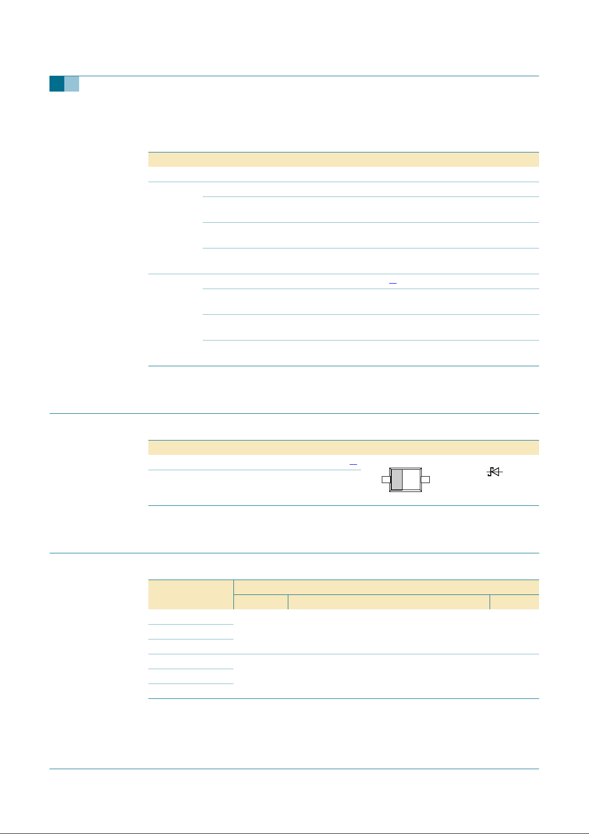
2. Pinning information
Table 3: Pinning
Pin Description Simplified outline Symbol
1 cathode
2 anode
[1] The marking bar indicates the cathode.
3. Ordering information
Table 4: Ordering information
Type number Package
PMEG2005EH - plastic surface mounted package; 2 leads SOD123F
PMEG3005EH
PMEG4005EH
PMEG2005EJ SC-90 plastic surface mounted package; 2 leads SOD323F
PMEG3005EJ
PMEG4005EJ
[1]
21
Name Description Version
12
sym001
9397 750 14515 © Koninklijke Philips Electronics N.V. 2005. All rights reserved.
Product data sheet Rev. 01 — 12 April 2005 2 of 13

Philips Semiconductors
4. Marking
Table 5: Marking codes
Type number Marking code
PMEG2005EH A3
PMEG3005EH A4
PMEG4005EH A5
PMEG2005EJ CC
PMEG3005EJ CD
PMEG4005EJ CE
5. Limiting values
Table 6: Limiting values
In accordance with the Absolute Maximum Rating System (IEC 60134).
Symbol Parameter Conditions Min Max Unit
V
R
I
F
I
FRM
I
FSM
P
tot
T
j
T
amb
T
stg
[1] Device mounted on an FR4 Printed-Circuit Board (PCB), single-sided copper, tin-plated and standard
footprint.
[2] Device mounted on an FR4 PCB, single-sided copper, tin-plated, mounting pad for cathode 1 cm2.
PMEGxx05EH/EJ series
0.5 A very low VF MEGA Schottky barrier rectifiers
reverse voltage
PMEG2005EH,
PMEG2005EJ
PMEG3005EH,
PMEG3005EJ
PMEG4005EH,
PMEG4005EJ
forward current Tsp≤ 55 °C - 0.5 A
repetitive peak forward current tp≤ 1 ms; δ≤0.25 - 7 A
non-repetitive peak forward
current
total power dissipation T
t = 8 ms square
wave
≤ 25 °C
amb
SOD123F
SOD323F
junction temperature - 150 °C
ambient temperature −65 +150 °C
storage temperature −65 +150 °C
-20V
-30V
-40V
-10A
[1]
- 375 mW
[2]
- 830 mW
[1]
- 360 mW
[2]
- 830 mW
9397 750 14515 © Koninklijke Philips Electronics N.V. 2005. All rights reserved.
Product data sheet Rev. 01 — 12 April 2005 3 of 13

Philips Semiconductors
6. Thermal characteristics
Table 7: Thermal characteristics
Symbol Parameter Conditions Min Typ Max Unit
R
th(j-a)
R
th(j-sp)
[1] Schottky barrier diodes thermal run-away has to be considered, as in some applications the reverse power
losses PR are a significant part of the total power losses. Nomograms for determining the reverse power
losses PR and I
[2] Device mounted on an FR4 PCB, single-sided copper, tin-plated and standard footprint.
[3] Device mounted on an FR4 PCB, single-sided copper, tin-plated, mounting pad for cathode 1 cm2.
thermal resistancefrom junction
to ambient
SOD123F - - 330 K/W
SOD323F - - 350 K/W
thermal resistancefrom junction
to solder point
SOD123F - - 60 K/W
SOD323F - - 55 K/W
F(AV)
PMEGxx05EH/EJ series
0.5 A very low VF MEGA Schottky barrier rectifiers
in free air
rating will be available on request.
[1] [2]
[1] [3]
- - 150 K/W
9397 750 14515 © Koninklijke Philips Electronics N.V. 2005. All rights reserved.
Product data sheet Rev. 01 — 12 April 2005 4 of 13
 Loading...