

Timer-Counters PM 6670...72
9499 460 10411 820215


Timer-Counters PM 6670...72
9499 460 10411 820215


Important
As the instrument is an electrical apparatus, it may be operated only by trained personnel. Maintenance and repairs may also be carried out only by qualified personnel.
Please note
In correspondence concerning this instrument, please quote the type number and serial number as given on the type plate.
Contents
- 1. Introduction..... 4
- 2. Technical specification..... 5
- 3. Directions for use....................................
- 4. Controls and connectors....10
- 5. Ciruit diagrams......12
1. INTRODUCTION
High resolution computing frequency counting
By making a synchronized multipleperiod measurement and computing the reciprocal value these timer/counters perform high resolution frequency measurements on all low frequency signals. The built-in microcomputer eliminates traditional ±1 cycle errors and as a result gives at least seven digits resolution per second of measuring time. This avoids the need for long gate times, period measurements or phase-locked frequency multipliers, normally required to obtain a high resolution.
High time resolution
For time interval measurements the PM 6670/71/72 also feature a very high measuring resolution.
By using the time interval averag ing technique, these timer/counters greatly improve both the measuring accuracy and resolution.
Compared to single time interval measurements, the basic 100 ns resolution is improved by a factor of VN, where N is the number of time intervals being averaged.
With the PM 6670/71/72, N can be more than 108. The resolution then becomes:
Variable measuring time
A valuable microcomputer benefit is the continuously variable measuring time, which is no longer limited to decade steps. You could, for example, select a measuring time of 2.4 seconds if one second does not give sufficient resolution. This avoids the need to switch directly to a time-wasting 10 second measuring period.
High trigger accuracy...
Ultimately, no counter is better than its front-end circuitry. Therefore the PM 6670 series employs the best front-end circuit concept available.
These timer/counters feature special input signal conditioning configurations, which are optimized for respectively frequency and time interval measurements, e.g. either adjustable trigger levels for time interval measurements or adjustable sensitivity and noise immunity for frequency measurements.
... for time measurements
Meaningful use of the averaging technique is made through the highspeed synchronizers and equalized input channels. Amplifiers and Schmitt-trigger circuits for both start and stop channel are all on the one IC-chip, thereby avoiding differences in delay and rise-times, such as are found in conventional counters. This reduces systematic trigger errors which cannot be eliminated by averaging.
Systematic trigger errors are further reduced by the low hysteresis via the use of high sensitivity input amplifiers.
The PM 6671 and 6672 feature trigger level outputs on the frontpanel, allowing accurate measurements to be made of the set trigger level with a DVM. The trigger level can also be positioned accurately with respect to the waveform using an oscilloscope.
... for frequency measurements
For frequency measurements, the trigger control can be selected to act as a wideband; continuously variable input attenuator (x1...x100) to allow optimum matching of trigger sensitivity and noise immunity.
Trigger Hold-Off and Arming
The PM 6671/72 give you full control over the start conditions of a measurement. With an external gate signal, one can prevent the timer/counters from being triggered by unwanted signals. An arming pulse then enables the timer/counter to trigger on the first input signal.
Another useful feature, found on the PM 6671 is trigger hold-off, which avoids false stop triggering on spurious or unwanted signals.

Phase and RPM
Another microcomputer benefit in these timer/counters is the possibility of new measuring functions – such as phase and RPM (revolutions/minute) – which are not normally found in counters.
A simultaneous measurement of period duration and the phase delay between two signals allow the microcomputer to calculate and display phase delays directly in degrees.
Choice of crystal oscillators
|
PM 667./0. version
including timebase option |
/01 standard version |
/02 version
PM 9678 |
/03 version
PM 9679 |
/04 version
PM 9690 |
/05 version
PM 9691 |
|---|---|---|---|---|---|
|
Stability
against |
Standard | тсхо | Oven | Oven | Oven |
|
Ageing: /24 h
/month /year |
n.a.
< 5 x 10 -7 < 5 x 10 -6 |
n.a.
< 1 x 10 -7 < 5 x 10 -7 |
n.a.
< 1 x 10 -7 < 5 x 10 -7 |
< 1.5 x 10
-9
< 3 x 10 -8 < 1.5 x 10 -7 |
<5 x 10
-10
<1 x 10 -6 <7.5 x 10 -8 |
|
Temperature:
050°C ref. to + 23°C |
< 1 x 10 -5 | < 1 x 10 -6 | < 1 x 10 -7 | < 3 x 10 -8 | < 5 x 10 -9 |
|
Change in measuring -
and supply mode: line/int. battery/ext. DC 12 V., 28 V |
< 3 x 10 -7 | < 5 x 10 -8 | < 1 x 10 -8 | < 3 x 10 .9 | < 3 x 10 .9 |
| Line voltage: ± 10 % | < 1 x 10 -6 | < 1 x 10 .9 | <1 x 10 -9 | < 5 x 10 -10 | < 5 x 10 -10 |
|
Warm-up time to reach:
10 7 of final value |
n.a. | n.a. | < 10 min | < 15 min | < 15 min |
Choice of timebase oscillator
The timebase crystal oscillator determines the accuracy limit of the counters.
Note that even the most stable version (5 x 10⁻¹⁰/24 h) can be operated from internal batteries. This unique feature is achieved by specially developed oven-stabilized crystal oscillators with extremely
low power consumption. Thus laboratory accuracy is now available for field applications — without irritatingly long warm-up times after changing location.
By means of the external reference input, you can use your own frequency standard, when available.
2. TECHNICAL SPECIFICATION
Measuring modes
Frequency
Range: 0.1 Hz...120 MHz (PM 6670, 6671). 0.1 Hz...1 GHz (PM 6672).
Mode: Input-signal synchronized, high resolution computing measuring method (reciprocal).
Signal mode: CW, SINGLE BURST, MUL-TIPLE BURST FREQUENCY AVERAGE. In the FREQUENCY AVERAGE mode (rear panel selectable), the counter measures the average of a multiple of frequency samples. Samples are taken with external gate control (≥500 ns) and totalized during the selected measuring time (10 ms...96 s) to allow multiple burst frequency measurements or to sample frequency sweep profiles.
LSD displayed: 10-7 Hz...103 Hz (PM 6670, 6671). 10-7 Hz...104 Hz (PM 6672), depending on measuring time and input frequency. At least 7 digits displayed per second of measuring time.
Resolution: LSD*.
Inaccuracy (rel.error):
+ resolution + trigger* error = rel. time FREQ measuring time base-error.
Period average
Range: 100 ns...100 s
LSD displayed: 10-15...10-5s, depending on measuring time and period duration. At least 7 digits displayed per second of measuring time.
Resolution: LSD*.
Inaccuracy (rel.error):
+ resolution + trigger* error + rel. time PERIOD measuring time
Time interval A to B; single
Range: 100 ns...108 s.
LSD displayed: 10-7s...10°s.
Resolution: LSD*.
Inaccuracy (rel.error): = resolution = trigger* error TIME INT base error.
Pulse width A
Pulse width measurements are similar to single time interval measurements. Both start and stop triggering take place in channel A, with common trigger level setting and automatic trailing edge trigger slope inversion with respect to selected leading edge trigger slope.
All other specifications are identical to single time interval. High resolution, pulsewidth measurements on narrow pulses can be made in the time interval average mode with manual selection of common source and stop slope polarity.
Time interval A to B; average
Range: 0 ns...100 s.
LSD displayed: 10-15s...10-6s, depending on measuring time and time interval.
Resolution:
10-7s or, 1 LSD unit, whichever is greather. √N
Inaccuracy (rel.error):
| + 4 ns = resolution + | trigger* error |
|---|---|
| TIMEINT | VN Y TIME INT |
| ± rel. time base error. |
Number of intervals averaged (N):
Measuring time x interval repetition rate.
Minimum dead time from stop to start: 300 ns.
Note: Input signal must be repetitive and asynchronous with respect to the time base.
Count A
Totalize range: 1...1017, with indication of M-pulses and G-pulses beyond the 108 display range.
Pulse pair resolution: 80 ns.
Mode:
Manual: Start-stop by DISPL. HOLD push button. Sequential start-stop periods are accumulated or individually totalized after reset.
External: Totalizing interval controlled via input B, selectable: count A gated during pulse duration on B or count A gated between start and stop pulse on B.
Inaccuracy: Pulse repetition rate A x trigger* error B.
Phase A-B
Phase is the result of a simultaneous time interval average and period average measurement. The maximum phase range is therefore limited, due to the 300 ns dead time between stop and start of the next time interval, and consequently frequency dependent. For phase measurements between 180° and 360° on high frequency signals, it is recommended to measure the complementary phase 0°...180° by changing the input leads (phase B to A).
Phase range: 0.1°...360° x [1-(300 ns x FREQ)]:
| 1. (000110 / 1. | ||
|---|---|---|
| Example | 0.1°359.995° | at 50 Hz |
| 0.1°357.3° | at 25 kHz | |
| 0.1°180° | at 1.666 MHz |
Frequency range: 0.03 Hz ... 1.6 MHz
LSD displayed: 10-6...10-2 degrees, depending on measuring time and phase difference.
Resolution:
Inaccuracy (rel.error):
Number of input cycles averaged (N): Measuring time x FREQ A.
Minimum input signal: 100 mVrms.
Phase jitter tolerance: The tolerated phase jitter peak-value ≤ phase difference, i.e. phase jitter around 0° should not cause consecutive measurement results of slightly above 0° and slightly below 360°, since the toltal measurement result is the statistical average of all individual results.
Ratio
Range:
LSD displayed: 10-7...10°
Resolution: LSD*.
Inaccuracy (rel.error):
± resolution RATIO ± rel. trigger* error B.
Note: Frequency ratio measurements
FREQ A (or C)0.01 Hz120 MHz (or 1 GHz)FREQ D50 kHz50 kHzcan also be made in the frequency mode,<br/>by making use of the external reference<br/>input D. However, this arrangement does
not give correct decimal points.
** C only on PM 6672.
RPM
The RPM (revolutions per minute) mode is similar to the frequency mode. The measured frequency is multiplied x 60, before being displayed.
Range: 0.6 RPM...10a RPM (with one pulse per revolution).
LSD displayed: 10-7 RPM...10° RPM, depending on measuring time and RPM.
Resolution: LSD*.
Inaccuracy (rel.error):
+ resolution + trigger* error + rel. time RPM measuring time base error.
* see definitions.
Auxiliary functions
Measuring time
The measuring time is "continuously" variable (33 steps/decade): 10 ms...96 s, with clear setpoints at 10 ms, 100 ms, 1s, 10 s and 96 s. Selected measuring time is displayed, without any delay when depressing the measuring time control.
The actual measuring time equals the selected measuring time plus the time needed to synchronize the measurement with an integer number of cycles of the input signal (Reciprocal measurements are synchronized with multiples of 10 input cycles).
In the FREQUENCY AVERAGE mode, the measuring time can be externally controlled to make burst frequency average measurements.
Hold-off PM 6671 only
With trigger hold-off activated, the counter ignores re-triggering (channel A) or stop triggering (channel B) during the set hold-off time. The hold-off time can be digitally measured by pressing CHECK. Applicable in all time modes.
Range: 200 us... 200 ms. in period, time interval and pulse width mode, the set hold-off time is visible with CHECK depressed
On/off indication: LED indicates when hold-off is activated
Monitor: The selected hold-off duration can be made visible via the gate monitor output
On Stand By
In "ST BY" position, power is available to maintain an ovenized crystal oscillator heated and to recharge the optional battery pack
Check
10 MHz internal reference connected to logic circuitry. Self-test of most measuring functions can be selected. By using this mode, the COUNT function provides a stop-watch facility.
Display hold
Depressing "DISP HOLD" button sets display time to infinite and freezes the last measurement result. A new measurement can be initiated using reset
In the COUNT mode, the "DISP HOLD" control is used to start and stop manual totalizing.
Reset
Manual via pushbutton or electrical via input E.
Input and output specifications
Inputs A and B
Frequency range: DC coupled: 0 120 MHz
AC coupled: 50 Hz...120 MHz Rise time: Approx. 4 ns.
Sensitivity:
DC coupled: 10 mVrms sine wave or 30 mVpp (0...75 MHz). 20mVrms sine wave or 60 mVpp (75...120 MHz)
AC coupled: 10 mVrms...100 mVrms sine wave (50 Hz...75 MHz). 20 mVrms...100 mVrms sine wave (75...120 MHz).
Attenuation: x 1/x 10 fixed.
For frequency related measurements, the fixed attenuator can be used in combination with the continuously variable attenuafor x1...x10 (AC coupled position).
Noise immunity/hysteresis band
DC coupled: approx. 20mVpp/200mVpp AC coupled: approx. 20 mVpp....2Vpp.
Dynamic input voltage range:
| DC coupled: | 30 mV pp 5 V pp / |
|---|---|
| 300 mVpp50 Vpp | |
| AC coupled: | 10 mVrms 2 Vrms |
| 100 mVrms 20V- |
Trigger level:
DC coupled: -2.5V...+2.5V/ -25V. +25V
AC coupled: fixed 0V; level control acts as continuously variable attenuator, which is more suitable for frequency related measurements
Trigger level output, not available on PM 6670: Set trigger voltages -2.5 V...+2.5 V, available on 1 mm lacks at the front for monitoring of set trigger level.
Trigger indicators, not available on PM 6670: Tri-state LED trigger lights to indicate trigger status:
On: trigger level is too low
Blinking: triggering occurs, input signal crosses hysteresis band.
Off: trigger level is too high.
Coupling: DC/AC
Impedance: Approx. 1MOhm//35 pF, independent of sep/com switch position.
Channel input: Separate A and B or common A
Noise filter: Switchable 50kHz Low pass filter in channel A. Noise suppression approx. 40 dB at 1 MHz.
Maximum voltage without damage: DC: 300V
AC: 260Vrms at ≤440 Hz declining to 12 Vrms at ≥1 MHz (in ATT x 1 position). 260 Vrms (in ATT x 10 position).
Input C, PM 6672 only
Frequency range: 70 MHz...1 GHz.
Operating input voltage range:
15 mVrms...12 Vrms ( 70 MHz...800 MHz). 25 mVrms...12 Vrms (800 MHz...1 GHz). Impedance: 50 Ohm nominal; VSWR <2. Coupling: AC.
AM tolerance: 98%, minimum signal must exceed minimum operating input voltage.
Maximum voltage without damage: 12 Vrms; overload protection with PIN diodes.
Ext. reference and Ratio input (channel D). not available on PM 6670
Frequency range: 1kHz...10MHz.
Sensitivity: 500 mVrms
Impedance: Approx. 2kOhm
Coupling: Ac.
Max. voltage without damage: 25 Vrms
Note: As external reference frequency only 10 MHz will give correct decimal point and unit indication. With the optional frequency multiplier PM 9697 references of 1 and 5 MHz can also be accepted.
Internal standard output (channel D).
not available on PM 6670 Crystal frequency: 10 MHz
Output level: LS-TTL compatible.
Output impedance: Approx, 400 Ohm Coupling: DC
Overload protection: Short-circuit proof.
Ext. arming/Freq-avg/ Reset (channel E)
- not available on PM 6670 A 3-position rear panel switch gives choice of external control over
- ARMING: In this position, the counter is prevented from starting a new measurement when input E is high. A high-to-low going pulse arms the counter to start a new measurement
Note: Arming not applicable in COUNT A, manual mode
FREQUENCY AVERAGE: Frequency measurements (max. 100 MHz) and period measurements are interrupted when input E is high. The measurement is continued again when input E is low. Each individual frequency sample must contain at least 20 pulses (FREQ mode) or 2 puises (PERIOD mode)
The effective measurement time (defining resolution and accuracy) is the sum of external gate times that occurs during the selected measurement time.
EXT. RESET-START: Electrical reset, equivalent to the front panel RESET pushbutton. (See HOLD and RESET). Counter is reset when input E goes high. A new measurement can be made after input E has returned low.
input levels:
High: ≥2V Low: ≤0.5 V.
Input impedance: Approx. 2kOhm.
Max. input voltage without damage: ±25V.
Minimum pulse duration:
| Arming and frequency avg: | 500 ns. |
|---|---|
| External reset: | s. |
Gate monitor output (rear).
not available on PM 6670 The date status monitor output permits observation on an oscilloscope of the measured time interval and the trigger hold-off time (PM 6671 only).
Output level:
Main gate open: approx. 0.4 V. Hold-off active: approx. 1.2V
Main gate closed: approx. 2.5V
Output impedance: Approx. 1.5 kOhm.
Delay: Internal delay between actual triggering and gate monitor output is approx. 150 ns
Overload protection: Short circuit proof.
General
Display
Read out: 8 digits, 7,6 mm high-efficiency LED's. Microprocessor control of display format, decimal point and unit indication: Hz, kHz, MHz, GHz, ns, us, ms and s.
Display time: Continuously variable 80 ms...96 s plus DISP HOLD.
Gate lamp: Indicates that main-gate is opened and measurement takes place.
ST BT: Stand-by indication with LED when instrument is not switched ON.
REMOTE:** Indicates when control over counter is taken by the installed BUS interface option (IEC 625 - IEEE 488).
Low-battery:** Indication by blinking display some 15 min. before recharging is needed.
Power requirements
In addition to the normal line voltage supply, the PM 6671 and PM 6672 can also be powered from an optional battery pack or external DC voltage.
Line: 115/230V ± 15%; 45...440 Hz; <25 VA.
Internal battery unit:** PM 9693.
External DC Cource:**
Voltage: 11.8V...28V; 4.5...8W depending on version and options installed. Connector: Battery jack fitting DIN 45323.
Line interference: Below VDE 0871 (B) and MIL STD 461.
Safety: According to IEC 348 and CSA 556 B.
** not available on PM 6670.
Dimensions and weight
Width: 210 mm (8.25 in). Height: 89 mm (3.8 in). Depth: 280 mm (11.0 in). Weight: Net: approx. 2.5 kg. Shipping: approx. 3.6 kg.
Environmental conditions
Temperature:
Rated range of use: - 5°C...+50°C. Storage and transport: -40°C...+70°C. Humidity:
Operating: 10...90% RH, no condensation. Storage: 5...95% RH.
Altitude/Barometric pressure
Operating: 5000 m (15000 ft) - 53.3 kN/m2. Storage: 15000 m (50000 ft) - 15.2 kN/m2.
Vibration test: According to IEC 68 Fc. Bump test: According to IEC 68 Eb. Handling test: According to IEC 68 Ec.
Transport test: According to NLN-L88.
Definitions
LSD displayed
Unit value of Least Significant Digit, displayed.
For FREQUENCY, PERIOD AVERAGE, RPM and PHASE:
LSD = FREQ or PERIOD or RPM or 360° 10' Hz
For RATIO: LSD =
= 2.5 x prescaling factor (P) x RATIO measuring time x FREQ A or C
Channel A, all models (P) = 1
(P) = 256 Channel C, PM 6672.
For SINGLE TIME INTERVAL and PULSE WIDTH:
LSD = 100 ns (for times <10 s).
LSD = (for times ≥10s).
For TIME INTERVAL AVG: LSD =
2.5 x 10⁻⁷ s meas, time x time int, rep, rate in Hz
All calculated LSD's shall be rounded to nearest decade (e.g. 5 ns will be 10 ns and 0.4 Hz will be 0.1 Hz) and cannot exceed the 8th digit.
Resolution
For multiple event measurements:
FREQUENCY, PERIOD AVERAGE, RPM and RATIO, the resolution is the smallest increment between two measuring results. being most often 1 LSD unit. Due to arithmetic truncation, the resolution can be 2 LSD units if:
LSD x measuring time FREQ or PERIOD or RPM or RATIO
but can then be reduced to 1 LSD unit, by doubling the measuring time.
For single event measurements:
PULSE WIDTH and SINGLE TIME INTER-VAL, the measuring resolution is 100 ns. (one clock pulse). The counter can accumulate up to 1015 clock pulses, of which only the 8 most significant digits are shown.
For statistical measurements:
TIME INTERVAL AVERAGE and PHASE. the measuring resolution is the smallest increment between two measuring results, with confidence level of 95%.
Trigger error
Trigger error is the absolute measurement error due to noise on the input signal causing a too early or too late triggering.
For any waveform (FREQ, PERIOD, RATIO, RPM and PULSE WIDTH):
peak-to-peak noise voltage signal slope (V/s)
For sinewave (FREQ, PERIOD, RATIO, RPM):
FREQ x TT x S/N ratio
Example: For S/N ratio of 100 (40 dB) and 1 second measuring time, the trigger . error is: 3 x 10⁻³ FREQ
For separate source TIME INTERVAL:
peak noise voltage (input A) + signal slope A (V/s) peak noise voltage (input B) signal slope B (V/s)
For PHASE:

S/N ratio (input B)
Note: S/N ratios calculated with peak-topeak signal and noise values.
Optional accessories
Rack mounting
The PM 6670-series counters can be fitted into a standard 19 inch rack, using adaptor PM 9669/01 or PM 9669/02 for one or two instruments respectively.

Carrying case PM 9672
To protect the instrument during transport and storage, an ever-ready case PM 9672 is optionally available.
Battery unit PM 9693
The PM 9693 is a rechargeable battery unit for mounting inside the PM 6670series counters. The unit contains two standard 6V, sealed batteries of lead-acid type.
Battery capacity (typical at 20°C): 30Wh; sufficient for 4 hours operation for the /01 and /02 models. For the high stability /03, /04 and /05 models, the capacity is sufficient for 3 hours operation or 20 hours stand-by.
Battery voltage: 12V nominal.
Recharging time: 5h to approx. 75% or 10 h to >90% of full capacity.
Recharging power: From counter <12W.
Battery low indication: By blinking display, 10...15 min. before recharging is needed.
Temperature: Operating: 0...+40°C.
Storage: -40...+50°C. Other environmental conditions as for
PM 6670-series of counters.
Weight: 1.4 kg (3.11b).
BCD-output and Display offset unit PM 9694
8
The PM 9694 converts and buffers the counters serial BCD output data into parallel form. The unit offers also the possibility of adding or subtracting a programmable value to the measured value before being displayed and output. This latter feature allows adding or subtracting a reference frequency to the measured frequency e.g. measurement of tuned receiver frequency, by measuring the local oscillator (IF offset).
Installation: Inside the counter, BCD-output and offset inputs available on rear panel.
Output signals: 8 ×4 parallel data lines for 7 most significant digits plus decimal point; 8-4-2-1 BCD, TTL positive true logic plus 6 lines for exponent.
Ready: A low going pulse is given when measurement and data conversion have been finished; TTL level; pulse duration: approx. 40 us.
Input command signals:
Ext. start: A low level on EXT START disables counting, when returned high, a new measurement will be initiated.
Inhibit: Data transfer is inhibited when signal is low.
Offset: Two different values can be programmed by soldering diodes on circuit board.
External selection by logic levels to select: offset on-off and offset value 1 or 2.
Connectors:
BCD-output: Amphenol or Cinch Series 57 Micro-ribbon.
Offset selection inputs: 2 mm banana sockets.
Analog recorder output PM 9695
The digital-to-analog converter PM 9695 provides a high resolution analog output e.g. for recording frequency stabilities of oscillators, filters and crystals on a Y-t chart recorder. In frequency control systems, having analog feed-back, the DAC serves as an extremely accurate frequency-voltage converter. The PM 9695 permits conversion of any three consecutive digits out of the total of nine, as such it functions as a magnifying glass to focus on just that part of the read-out which is most important. In the normal mode 000 is converted in a zero analog output and 999 into a full scale defelction.
In the offset mode, however, 500 gives a zero output and 000 a mid-scale deflection. Thus, for a display changing between 9.9999999 and 10.0000000 MHz, it is possible to record the frequency on the center of the strip chart, rather than shooting between zero and full scale.
Installation: Inside the counter, output connector and NORMAL/OFFSET-mode switch available on rear panel.
- Decade conversion: Any 3 consecutive digits can be selected. The value of the least significant of the 3 digits can be selected with a 12 position switch.
- Normal mode: Analog output is directly proportional to digital input. 000 produces 0.000V. 999 produces 0.999V.
- Offset mode: Adds 500 to digital input to obtain half scale offset. 500 produces 0.000V. 499 produces 0.999V.
Output:
Zero output: 0V. Full scale deflection: 0.999V. Connector: BNC.
Accuracy: ±2 mV.
Nonlinearity: ±0.5 mV.
- Temperature coefficient: ±(0.1mV + 0.03% of reading)/°C.
- Output impedance: 100 Ohm ±1%.
Weight: Approx. 160 g (0.35 lb).
IEC 625-IEEE 48 8 BUS interface PM 9696
When provided with this interface option, the PM 6671 and PM 6672 timer/counters are fully BUS compatible. Talker and listener functions in these counters allow bi-directional bus communication, including programmability of all major functions.
Installation: Inside the counter, connector and address switch available on rear panel.
Interface function repertoire: Frequency A, Period A, Single Time Interval A— B, Time Interval Average A— B, Pulse Width A, Count A (manual), Count A gated by B, Count A start/stop by B, Ratio A/B, Phase A— B, RPM, Hold-Off on/off, frequency input channel selection A or C, Frequency average/arming on/off, Display hold, Measuring time, Trigger (start measurement), Device clear, Program data out, Service request disable/enable.
- BUS commands: SH1, AH1, T5, L3, SR1, RL1, DC1 and DT1.
- Connector: IEEE recommended type. Amphenol or Cinch Series 57 Microribbon. Compatibility with IEC recommended type is obtained via the optional screw-on IEEE-to-IEC connector transi-
Ext. reference frequency multiplier PM 9697
tion PM 9483/50.
To accept external reference frequencies other than 10 MHz, the frequency multiplier PM 9697 can be ordered.
With this option installed, the PM 6670series counters can accept external reference frequencies of 1MHz, 5 MHz or 10 MHz. All other input specifications as for external reference input.
- PM 9581: 50 Ohm feed-through termination; 3W.
- PM 9585: 50 Ohm feed-through termination; 1W.
- PM 8923: 120 MHz*; 1 MOhm probe-set; 1:1 and 1:10.
- PM 9639: 1.5 GHz*; 500 Ohm probe-set; 1:10.
- PM 8943: 650 MHz; 50 Ohm/1 MOhm FET probe-set.
- Indicated frequency with limited loss of sensitivity suitable for frequency measurements. For amplitude measurements, a limited frequency range is specified in the T& M catalogue.
ATTENTION
The counters can NOT simultaneously be equipped with more than one of the following options: PM 9693, PM 9694, PM 9695 and PM 9696.
The multiplier PM 9697 can only be installed in the /01 counter versions.
3. DIRECTIONS FOR USE
General information
Before connecting the counter to the line (mains), visually check the cabinet, controls, connectors, etc, to ascertain whether any damage has occured in transit. If any defects are apparent, do not connect the counter to the line.
In the event of obvious damage, missing parts or if the safety of the counter is suspected, a claim should be made to the carrier immediately. A PHILIPS Sales or Service organisation should also be notified in order to facilitate the repair of the counter.
Grounding
The counter is connected to ground via a three-core line cable, which must be plugged into a socket outlet with a protective ground contact. No other method of safety grounding is permitted for this counter.
Any interruption of the protective ground, inside or outside the counter is dangerous. Line extension cables must always have a protective ground conductor.
When the counter is brought from a cold to a warm environment, condensation may cause a hazardous condition. Therefore ensure that the grounding requirements are strictly met.
Opening of the cabinet or removing of parts, except those to which access can be gained by hand, is likely to expose live parts and accessible terminals that can be dangerous to life.
The counter shall be disconnected from all voltage sources before any adjustment, replacement, maintenance or repair is effected with the covers removed.
If adjustment or maintenance of the counter with the covers removed is inevitable, it shall be carried out only by a skilled person, who is aware of the hazard involved.
Bear in mind that capacitors inside the counter may still retain their charge, even if the counter is disconnected from all voltage sources.
All components on the primary side of the line transformer are CSA approved and should only be replaced with original parts.
Line voltage setting
Before connecting the counter to the line, ensure that it is set to local line voltage.
On delivery, the counter is set to either 115V or 220V, as indicated on the line voltage selector on the rear panel. If the voltage setting is incorrect, set the line voltage selector in accordance with the local voltage, before connecting the counter to the line.
External battery operation
For field applications, the counter can be operated from an external 11.8...28V DC supply, connected to the EXT BATT socket.
Connecting the counter to both the line and an external battery at the same time, gives a power back-up facility that maintains heating of the oven oscillator and recharges the optional internal battery pack PM9693 when fitted.
Fuses
The counter is protected by thermal fuse, located in the line transformer, and a secondary fuse (1.6A fast-blow) on PCBU1. Remove the line plug before fitting a fuse. Ensure that only fuses of the specified type are used.
If the counter is set for operation on 115V line voltage, but is connected to a 220V supply, the thermal fuse will blow immediately to protect the counter.
Type
Service code number 4822 252 20007 Thermal fuse 1.6A fast-blow fuse 5x20mm 4822 253 20022
Operating position
The counter can be operated in any desired position. A folddown tilting handle can be rotated and locked in several fixed positions by first depressing the knob in the center of each hinge.
Front cover
The front panel controls and connectors can be protected by a plastic snap-on front cover.
Cleaning the counter covers
The top and bottom covers, lacquered with Nextel suède coating, need special treatment if the surface gets soiled. The 3M Company has developed a "Doodlebug Pad" (Catalogue No.8440) which when soaked in water, ethanol or common household cleaning agent, will penetrate holes and pores to restore its former lustre.
Abrasive cleaning pads will result in surface scratches. Although the Nextel suède coating is ethanol resistant, it is susceptible to methylated spirit, which could damage the surface due to one of the denaturing substances present.
ち

4. CONTROLS & CONNECTORS
POWER
Supplies power to the counter in the ON, depressed position. In the ST BY, released position, the counter is switched off, but power is still available for an optional oven oscillator and a rechargeable battery. A decimal point marked ST BY indicates the stand-by mode.
This is a secondary power switch. Even in the stand-by mode the counter contains live conductors and parts. The line cord (mains lead) must be removed to disconnect power from the counter.
CHECK
When depressed, the internal 10MHz standard signal is connected to the logic circuits. In conjunction with the function selector rotary switch, CHECK enables a self-test of most measuring functions.
RESET
When depressed, resets the counter and blanks the display. On release, RESET initiates a new measurement.
DISPL HOLD
When DISPL HOLD is depressed, the display time is set to infinity. A new measurement can be initiated with the RESET push-button.
MEASURING TIME PUSH TO READ
The measuring time can be set between 10ms and 96s for optimum resolution and measuring speed.
When pushed, the set measuring time is displayed.
HOLD OFF, PM6671 only
During the set hold-off time, the counter ignores all input events that should have ended the measuring cycle. To display the set hold-off time, select TIME INT SINGLE A-B and press CHECK.
Function selector rotary switch
RPM A
Sets the counter to perform a revolution per minute measurement on the signal connected to input A, provided that the transducer sends one pulse per revolution.
FREQ A FREQ A or C, PM6672 only
Sets the counter to perform frequency measurements on the signal connected to input A or input C. In the frequency average mode, rear panel selectable on PM6671...72, the counter measures the average of several frequency samples.
RATIO A/B
Sets the counter to measure the ratio between signals connected to input A and B up to 10MHz. To obtain full frequency range on PM6671...72, a ratio measurement can be done in the FREQ A or C mode by using input D set to EXT STD IN. However, this method does not give correct setting of the decimal point.
PHASE A-B
Sets the counter to measure the phase (in degrees) between signals connected to input A and B. Max frequency is 1.6MHz. The sensitivity knob should be pulled and set fully clock-wise. The ATT x10 push-button should be released.
COUNT A MANUAL
Sets the counter to totalize events (pulses or periods) on input A during the time interval between releasing and depressing the DISPL HOLD push-button.
The result can be accumulated with another count sequence or reset with the RESET button.
COUNT B _____ Gated by B
The counter will totalize events on input A, between the leading and trailing edge of the input B signal.
COUNT B _____ Start and Stop by B
The counter will totalize events on input A, between the start and stop event on input B.
PULSE WIDTH A
Sets the counter to measure the pulse-width of the signal connected to input A.
Time INT SINGLE A-B
Sets the counter to measure the time interval between pulses on input A and B.

TIME INT AVERAGE A-B
Sets the counter to measure the time interval average of a repetitive signal that is not synchronized with the used standard frequency.
PERIOD A
Sets the counter to measure the average period time of the signal connected to input A.
Input amplifier
ATT x10
When depressed, the sensitivity is attenuated by a factor 10 for input A or B. In DC mode the equivalent trigger level is multiplied by 10.
SLOPE 7
When depressed, the triggering occurs on the trailing edge instead of the normal leading edge.
50kHz FILTER
A low-pass filter to improve triggering of noisy signals with frequencies below 50kHz. Applies to input A only.
COM via A
Connects channel A and B internally. In this mode input B is disconnected.
TRIGGER LEVEL
When the rotary knob is depressed, the DC mode is selected and the trigger level is adjustable between – 2.5V and +2.5V.
Tri-state trigger indicators on PM6671...72 light to indicate trigger status:
- On = trigger level is too low
- Blinking = triggering occurs, i.e. input signal crosses hysteresis band
- Off = trigger level is too high
The trigger level output on the front panel of PM6671...72 makes it possible to measure the set trigger level. When ATT x10 is depressed, the trigger level is adjustable between – 25V and + 25V, but the output level is still – 2.5V... + 2.5V.
SENSITIVITY
When the rotary knob is pulled, the AC mode is selected and the sensitivity is adjustable between approx 10...100mVRMS
1GHz, PM 6672 only
When depressed, input C is connected. The sensitivity is adjusted automatically.
LED indicators REMOTE
Indicates that the counter is in the remote-controlled mode via the optional Bus Interface PM9696.
GATE
Indicates that a measurement is in progress.
Unit indicator
A multi-purpose 4-LED unit indicator.
For FREQ read: Hz, kHz, MHz, GHz. For PERIOD, TIME and PULSE WIDTH read: ns, µs, ms, s.
For COUNT read: µs/kHz = 103 pulses ms/MHz = 106 pulses s/GHz = 109 pulses
Rear panel, PM6671...72
EXT STD IN/INT STD OUT Input D
Two-position switch selection of using BNC connector D either as an output for the internal 10MHz standard signal or as an input for an external standard signal.
ARMING/FREQ AVERAGE/EXT RESET Input E
Three position slide switch for selecting the functions of input E.
GATE MONITOR
Enables observation on an oscilloscope of the measured time interval and the trigger hold-off time.
EXT BATT
Input from an external DC source 11.8...28V.
5. CIRCUIT DIAGRAMS

IN CON OUT COM IN OUT
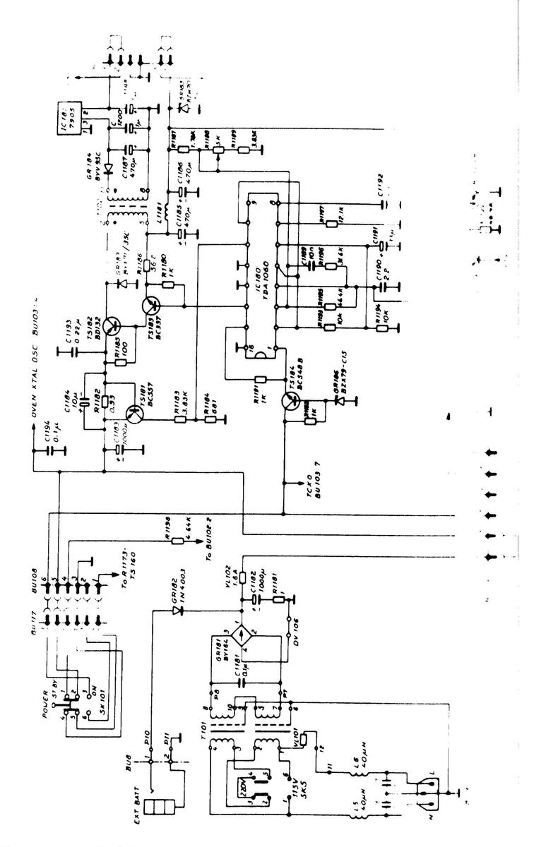
Fig. 5.2. Power supply PM 6671 and PM 6672
÷.
*, Port of PC-boord

15
÷

--------------------------------------

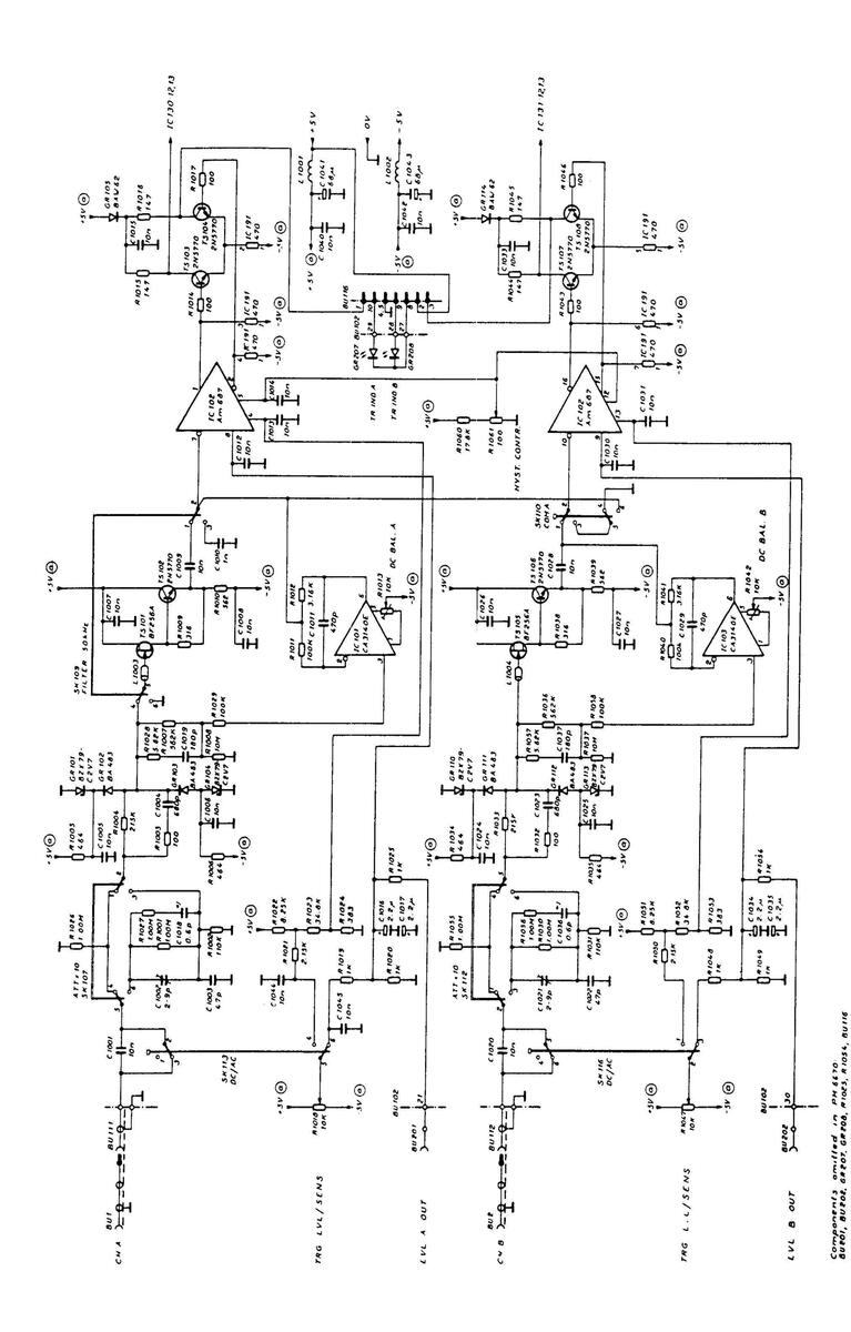
Fig. 5.6. Logic circuits PM 6671

19


 Loading...