

Page 1
Logic
Analyzers
PM
3551 A/10/30/50/70
Operating
9499 500 1
831013
2911
manual
A
PUBLICATION
® PHILIPS EXPORT B.V. - EINDHOVEN - THE
PRINTED IN THE NETHERLANDS
OF THE SCIENTIFIC
AND
INDUSTRIAL
EQUIPMENT
NETHERLANDS
DIVISION
- 1983
PHILIPS
Page 2

1.2
TABLE
Section
1
1.1
1.2
2
2.1
2.2
2.3
2.4
2.5
2.6
2.7
2.8
2.9
2.10
3
3.1
3.2
3.2.1
3.2.2
OF
CONTENTS
Description
INTRODUCTION
General
information.
•
Features
CHARACTERISTICS.
Logic
Logic
State
Timing
analyzer
analyzer.
Operation.
Display.
Display
modes.
Compare mode
Power
Environmental
Physical
Accessories
GENERAL
Information
Description
Front
Rear
supply
characteristics.
characteristics
and
DIRECTIONS
and
of
panel.
panel.
controls,
Options
Warnings
for
the
User.
connectors
and
display.
•
•
•
•
•
•
•
•
•
•
•
•
•
1.4
1.4
1.5
2.1
2.4
2.9
2.11
2.11
2.12
2.13
2.13
2.14
2.16
2.17
3.1
3.2
3.6
3.6
3.9
4
4.1
4.1.1
4.1.2
4.1.3
4.1.4
4.1.5
4.2
5
5.1
5.1.1
5.1.2
5.2
5.3
5.3.1
5.4
6
6.1
6.2
7
8
8.1
,
B.2
B.3
B.4
DESCRIPTION
Full
menus
Configuration
Trigger
Data
menu.
Compare menu
Options
OF
menu
menu •
•
menu
Condensed menus.
DESCRIPTION
OF
List
Selective
Compare
data
data
•
Graph.
Timing •
Timing
Sync
CONNECTION
compare
mode.
•
Input.
What
USER
else
to
MESSAGE
connect?
LIST.
OPERATION.
General.
Triggering
Selective
•
data
Compare.
THE
MENUS
THE
DATA
•
acquisition
DISPLAYS
•
•
•
•
•
•
•
•
•
•
•
•
•
•
•
•
•
•
•
•
•
•
•
4.1
4.3
4.3
4.7
4.17
4.21
4.27
4.32
5.1
5.3
5.7
5.8
5.9
5.12
5.15
5.16
6.1
6.2
6.3
7.1
8.1
8.2
8.2
8.4
8.4
PM
3551A
Operating
manual
Chapt.
1
SW
2.0
JGB401
October
13,
-)
1983
Page 3

1.3
TABLE
Section
9
9.1
9.2
9.2.1
9.2.2
9.3
9.3.1
9.3.2
9.3.3
9.3.4
9.3.5
10
10.1
10.2
10.3
10.4
11
12
OF
CONTENTS
INTERFACE
Printer
Disassemblers
Disassemblers
Non-volatile
Disassembler
A
Package.
M
Package.
N
Package.
R
Package.
Z
Package.
INSTALLATION
Unit
identifier
Additional
8-channel
Option
IEEE-488
RS
232-C
(cont'd)
Description
AND
OPTIONS
Interface.
.•
• • • .
General.
Accesories
memory. • • . • • • .
connection
and
• • • • •
.
INSTRUCTIONS
switch.
24-channel
50
board,
GPIB
CONTROL
MHz
timing
disa's
INTERFACE
INTERFAC~
state
analyzer
and
OPTION
. . • • •
display.
. • • •
FOR
OPTIONS. • . .
. . • •
•.
analyzer
• . . . . • • •
non-volatile
(PM
OPTION
. • • • .
•.
.
••••••
• • • •
memory.
8851/40)
(PM
8851/20)
.•
· . •
·
••
••
•
••
• .
.
•
9.1
·
9.2
•
9.4
9.5
•
9.7
9.10
9.11
·
9.18
9.29
9.39
•
9.46
.
10.1
10.3
10.4
10.5
10.10
•
11.1
•
12.1
13
PROBLEM
REPORTS
AND
CHANGB
REQUESTS
•...••.
•
13.1
PM
3551A
Operating
manual
Chapt.
1
SW
2.0
JGB401
October
13,
1983
Page 4
1.6
1.2.
A
interactive
parameters
of
The
can
from
trigger-word
various
The
use
certain
In
A
can
is
of
polling
FEATURES
functionally
the
system
extensive
be
combined
complex
models.
sequence
of
an
amount
this
mode
notable
be
specified
called
triggering
sequence)
organized
menu-display
for
triggering,
under
triggering
with
system
has
the
of
the
IF,
THEN,
of
delay
triggering
feature
"Trigger
of
as
when a
is
test.
clock
activities
same
different
ELSE
between
can
this
true
on
Sequence
defined
broken
keyboard/softkey
serve
capability
width
algorithm,
mode
or
the
user
capturing,
and
trigger-qualifiers,
or
from
as
the
trigger-words
with
the
be
selected
is
that
alternatively
Break"
repetitive
or
not
executed
comparing
of
statements.
mode
structure
in
setting
the 7 sequential
deep
number
the
as
the
as
pattern
branched
used
possiblity
True
selected
not
and
in
up
and
permits
of
input
can
or
False.
true.
provides
(eg. a loop
the
specified
in
combination
and
entering
counting
trigger-words,
or
nested
channels
be
defined
of
trigger
This
the
the
activities
capturing
loops.
of
by
placing
sequence
latter
capability
or
a
order.
with
data
the
the
a
mode
an
that
Each
The moment
occurrences
The
Logic
A
readout
obtained.
Special
The
COMBI
section
timing
analysis
Data
one
up
In
stored
The
instrument-setting,
to
of
to
the
instrument
of
and/or
Analyzer
of
features
mode
or
vice-versa,
channels
of
critical
be
captured
the
three
four
qualifiers
COMPARE
data
in
the
capturing
time.
can
elapsed
of
note
allows
are
mode, a
the
automatically
the
cross-referenced
state/time
is
selectable
available.
formats:
when
data
can
also
while
clocked
comparison
time
here
state
the
be
used
between
are
in
into
clock
List
stores
mains
be
delayed
for
making
two
points
the
COMBI
section
the
relationships.
sources.
can
or
voltage
to
SYNC
Timing.
with
the
be
the
mode
analyzer
made
current
state
by
states
time
and
be
triggered
the
For
between
supply
and/or
measurements.
in
a programm
the
SYNC
displays
sampling.
on
selected
each
mode-
clock
is
switched
captured
and
modes.
by
the
of
This
used,
function
trigger
can
timing
a number
enables
clock
there
data
off.
be
edges
and
of
of
are
PM
After
and
function
All
analyzer
to
store
retrieved
3551A
switching
up
to 4 additional
under a label.
Operating
on)
setting.
models
manual
the
can
Chapt.
instrument
be
equipped
settings.
1
comes up
with
Here
SW
2.0
in
the
option
each
JGB401
the
setting
initial
(non-volatile
October
is
default
stored
13,
mode-
memory)
and
1983
Page 5
In
the
TIMING
can
be
captured
The
PM
3551A
independently
This
allows
mode,
can
of
high
glitches
from
the
be
equipped
the
presence
precision
1.7
of a duration
data-stream.
with
timing
a 4
of
the 8 channel
measurements.
of
channel
as
little
300MHz
50
MHZ
as 5 nanoseconds
timing
section.
option,
Other
This
control
The
packages,
The
mnemonic
microprocessors.
Data
its
available
A
the
options
board
options
disassembly-packages
is
own
comprehensive
various
can
interface,
board
and
language
entered
threshold
for
functions
are
the
be
equiped
both
is
also a prerequisite
the
non-volatile
of
the
into
the
adjustment.
connecting
built-in
options
with
providing
allow
most
analyzer
the
diagnostic
of
the
board
an
GPIB
full
setting
the
currently
via
A
variety
system
analyzer
with
control
remote
memory.
user
available
8-channe1
under
program
and
standard
for
installation
to
view
of
convenient
test
can
to
assist
RS232C
interface,
control
captured
8
pods,
to
the
be
used
printer
or
a RS232C
of
the
instrument.
of
disassembly-
data
and
16-bit
each
analyzer.
in
provided
Pod-attachments
as
an
fault-finding.
in
aid
output.
the
with
to
test
are
PM
3551A
Operating
manual
Chapt.
1
SW
2.0
JGB401
October
13,
1983
Page 6
2.1
C H A R
ACT
E R
1ST
I C S
PM
3551A
Operating
manual
Chapt.
2
SW
2.0
JGB402
October
12,
1983
Page 7

2.
CHARACTERISTICS
The
instrument
Publication
safe
condition.
warnings
which
operation
348
and
has
for
The
should
to
maintain
been
designed
and
Class I instruments
present
be
Operating
followed
the
instrument
by
2.2
tested
and
Hanual
the
according
has
been
contains
purchaser
in a safe
to
IEC
suppll.ed
information
to
ensure
condition.
in
safe
a
and
Properties
guaranteed
stated
otherwise.
represent
specification
minutes.
OPERATION
TYPES:
expressed
for
ambient
the
characteristics
is
MODES:
in
Numerical
valid
numerical
temperatures
values
of
after
-
Logic
-
Logic
-
Comb:i
the
triggering
-
SYNC
Mode
cross-referenced
values
of
+5
without
an
average
instrument
State
Timing
Mode
Analyzer
Analyzer
where
of
where
with
stated
deg.C
tolerances
instrument.
has
the
the
LTA
timing
with
tolerances
•••
+40
are
warmed up
only
only
LSA
can
or
vice-versa.
analyzer
the
state
deg.C
typical
This
for
enable
data
analyzer
are
unless
and
15
the
is
data.
No
No
Type-numbers
of
State
of
50~z
Channels
Timing
PM3551A/10
Channels
PM3551A/30
35
PH3551A/50
35
8 8
PH3551A/70
59
59
PM
3551A
Operating
manual
Chapt.
2
SW
2.0
JGB402
October
12,
1983
Page 8
THRESHOLD - - - - - - -
2.3
SOOmV
SIGNAL
CENTERED AT
THRESHOLD
SWING
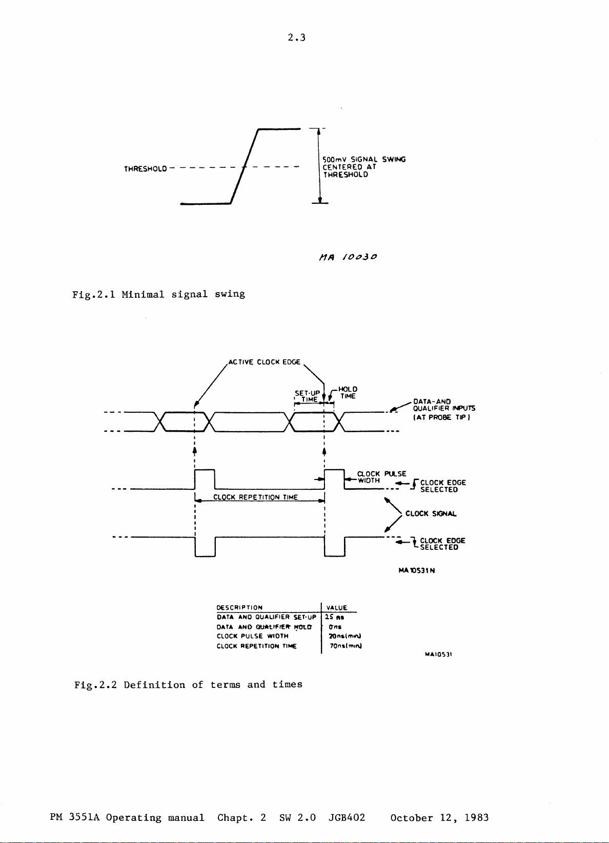
Fig.2.1
Minimal
---=X~iX
_
_____ ~ ...
signal
swing
lAC
I
I
I I
•
I I
n
.
I.
liVE
CLOCK
__________
. -
CLOCK
REPE TlTlON
EOGE--,",;,;",;"::~,,,
x~
TIME
:
-----:LJr--------iLJ
,..----
I
_ K
•
~
--,~
.1
1)
a.OCK
r WIDTH
~-------------
PU..SE
4-
"
--4-1CLOCK
MA
DATA·· AND
auALlFIE~
I
AT
rCLOCK
~
SELECTED
CLOCK
SELECTED
()S31
H'VTS
PROB£ TIP J
EDGE
SIGN
....
EDGE
N
PM
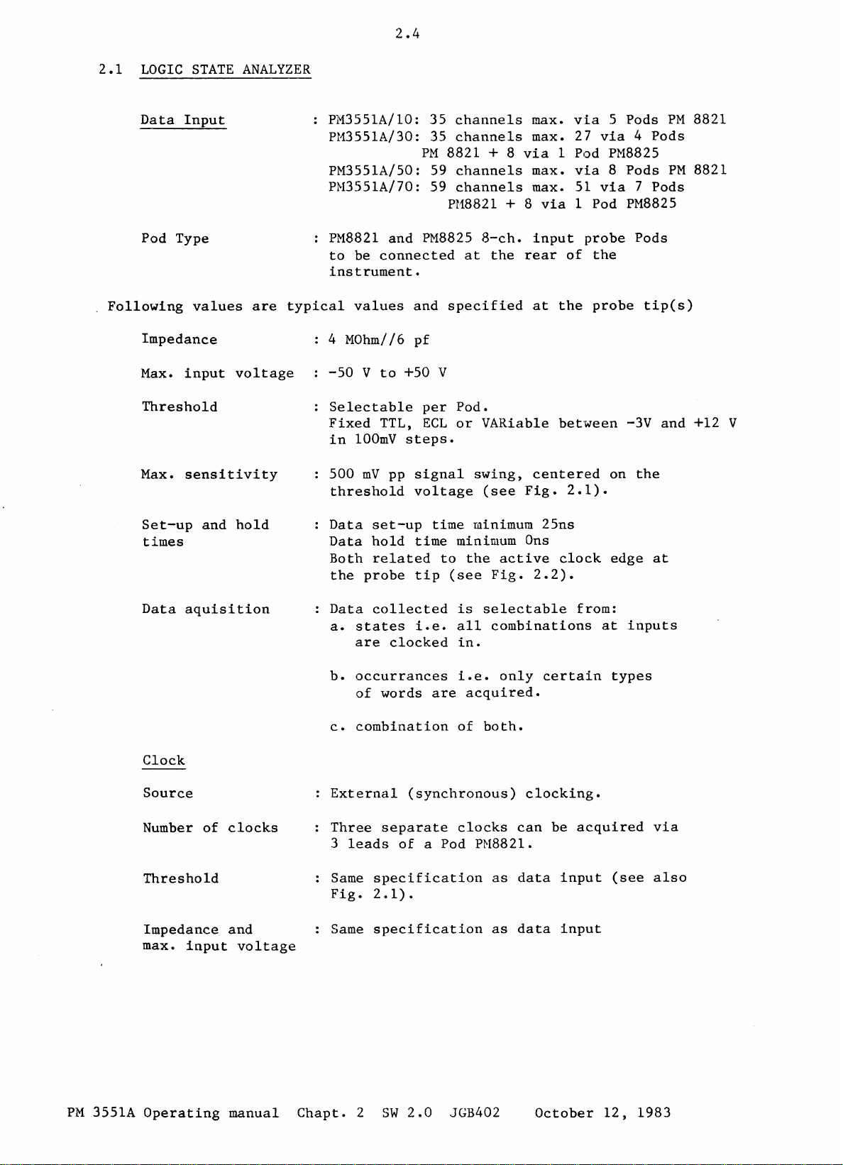
Fig.2.2
3551A
Definition
Operating
of
manual
DESCRIPTION
DATA ANO QUALIFIER SET-UP
OATA
AND
CLOCK
CLOCK REPETITION TlhIE 70nslmll\J
terms
Chapt.
0U*ttt:t£~
PULSE
and
2
~"
WIDTH lOns(mlt\ol
times
SW
2.0
VALUE
lS
ft.
(tns
JGB402
"'AI05)1
October
12,
1983
Page 9
2.1
LOGIC
STATE
2.4
ANALYZER
Data
Pod Type
Following
Impedance
Max.
Threshold
Max.
Set-up
times
Input
values
input
sensitivity
and
voltage
hold
are
PM3551A/10: 35
PM3551A/30: 35
PM3551A/50: 59
PM3551A/70: 59
PM8821
to
be
instrument.
typical
values
4 MOhm//6
-50 V to
Selectable
Fixed
in
100mV
500
threshold
Data
Data
Both
the
and
connected
+50 V
TTL,
steps.
mV
pp
set-up
hold
related
probe
channels
channels
PM
8821 + 8
channels
channels
PH8821 + 8
PM8825
and
specified
pf
per
Pod.
ECL
or
signal
voltage
time
time
minimum
to
tip
(see
max.
via
max. 27
via
max.
max. 51
via
8-ch.
at
VARiable bet'ween -3V
swing,
(see
minimum
the
the
active
Fig.
input
rear
at
centered
Fig.
25ns
Ons
2.2).
via 4 Pods
1 Pod
via 8 Pods
via 7 Pods
1 Pod
probe
of
the
the
probe
2.1).
clock
5 Pods
PM8825
PM8825
Pods
tip(s)
on
the
edge
and
at
PM
PM
8821
8821
+12 V
Data
max.
aquisition
Clock
Source
Number
Threshold
Impedance
of
input
clocks
and
voltage
Data
collected
a.
states
are
b.
occurrances
of
words
c.
combination
External
Three
3
Same
Fig.
Same
separate
leads
specification
2.1).
specification
is
i.e.
all
clocked
(synchronous)
of
in.
i.e.
are
of
clocks
a Pod PH8821.
selectable
combinations
only
acquired.
both.
can
as
data
as
data
from:
certain
clocking.
be
acquired
input
input
at
types
(see
inputs
via
also
PM
3551A
Operating
manual
Chapt.
2
SW
2.0
JGB402
October
12,
1983
Page 10

2.5
Clock
repetition
time
Clockpulse
Sampling
Clock
qualifiers
Number
Threshold
Impedance
max.
input
Sampling
width
and
voltage
Min.
Min.
70ns
20ns
Selectable
edge.
2
••• 4 clock
(input
Two
two
via
clock
are
channels.
Same
Fig.
Same
At
level.
are
specification
2.1).
specification
clock
True
possible
(see
Fig.
(see
Fig.
on
positive
qualifiers
a Pod PM8821)
qualifiers
interchangeable
as
as
edge
and
(see
and
False
at
Fig.
2.2).
2.2).
or
negative
are
fixed,
with
data
data
input
input
selected
combinations
2.2).
the
two
data
(see
qualifier
clock
other
also
Selection
Set-up
and
times
Memory
Format
Triggering
Source
hold
"I"
for a high
"0"
for
a low
"X"
for
don't
Data
Data
Both
A
set-up
hold
related
the
probe
The memory
second
memory
time
tip
depth
as a reference
1)
Internal,
(External
for
trigger
socket
level
level
care
time
(qualifier
minimum
minimum Ons
to
the
(see
Fig.
is
of
the
memory
2)
~~nual
TRIG
qualifier)
active
1K
(=1023)
same
for
or
IN
not
25ns
clock
2.2).
size
comparison
3)
External
is
also
edge
bits
is
input
in
use).
at
per
available
channel.
PM
3551A
Operating
manual
Chapt.
2
SW
2.0
JGB402
October
12,
1983
Page 11
2.6
1)
2)
3)
Internal
Manual
External
external
or
trig.
i.e.
trigger
qualifier
Triggering
by a
•
Parallel
•
Sequential
the
•
must
For
can
delays.
Trigger
The number
counted
Via
PM
enable
delay
TRIG
Immediate
be
all
be
"false"
Operator
input
8810
and
is
on up
counter,
and
Quasi
triggering
word)
Sequential
followed
trigger
made
with
words
triggering.
(see:
controlled
probes.
for
selectable
can
of
triggers
Delay
socket
the
to 7 words,
can
parallel
(ARM
Triggering.
immediately
modes,
up
to 7 words,
be
selected
and
STOP
TRIG
This
internal
as
IN
input
edge
be
selected
triggering
word(s)
all
combinations
can
be
Counter).
button.
and
acts
trigger
or
each
by word N+1.
Word
clocks
for
preset
PM8800
as
logic
level
delayed
for:
enable
N
and
"true"
and
or
an
active.
or
Following
probe
is
Input
Max.
Threshold
Sensitivity
Set-up
times
is
values
used.
Impedance
Input
and
when
used
are
typical
Voltage
hold
PM8800
The
external
possibilities:
•
When
all
external
•
When
•
5
the
don't
the
this
input
Connection
values
MOhm
+ 50 V
Fixed
500
mVpp
Signal
Signal
Both
the
(use
related
probe
the
internal
trigger.
internal
and
/1
TTL
signal
set-up
hold
'delayed'
input
cares,
acts
for
apply
15
pf
time
to
tip
offers
trigger
this
trigger
as a trigger
PM8810
only
swing
time
minimum
minimum Ons
the
active
(see
Fig.
function
input
Logic
when
(see
2.2).
the
word
acts
word
qualifier.
Trigger
the
Fig.
30ns
clock
in
following
is
set
as
an
is
defined
Probe
specified
2.1)
edge
the
trigger
as
at
menu)
PM
3551A
Operating
manual
Chapt.
2
SW
2.0
JGB402
October
12,
1983
Page 12

2.7
Set-up
times
is
used
Delay
Outputs
and
hold
when PM8810
Signal
Signal
Both
the
-
-
-
-MATCH
OUTPUT
word
and
related
probe
(use
the
trigger
In
the
in
the
as
states
in
occurrences
in
time
sequence
The
output
occurs,
next
The
3
The
trigger
delay
the
state
pulse
set-up
hold
'not-delayed'
menu)
trigger
range
OUT.
ON
list.
Match
clock
time
minimum
time
minimum
to
the
tip.
menu,
of 0 to
of
clock(s)
of
Is
activated
WORDS:-statement
is
TTL
high
and
remains
word
between
length
occurs.
input
out
connector
cycles
is
5ns
active
function
delay
64k
steps
word(s)
by
when
high
probe
+50
+/-15
always
50ns
clock
can
be
the
in
the
the
until
tip
amounts
nS.
more
edge
in
the
specified
MATCH
trigger
trigger
the
(PM
to:
than
at
8821)
60
nS.
Selective
Selection
Block
Selected
data
limits
data
acquisition
-RUN
-A
OUT.
data
acquisition.
The
delay
and
the
output
Output
-TTL
-Source
-Sink
-Short-circuit
-Max.
Up
data
Start
End
or
Samples
specific
clock(s).
specification:
compatible
current
current
ext.
to
two
acquisition
on a
on a certain
END.
The
between
voltage
different
certain
on
specified
word
output
internal
is
25
3
rnA
3
rnA
proof.
can
word,
and
is
TTL
+/-15
at
Voh=
at
Vol=
+
or
-25
blocks
be
selected.
word
or
word+trigger
clock(s).
samples
high
start
nS.
2,4
0,5
V.
of
on
on
during
and
v.
V.
selective
START.
delay,
specified
stop,
PM
3551A
Operating
manual
Chapt.
2
SW
2.0
JGB402
October
12,
1983
Page 13
2.8
Counter
-One
-A
specific
specific
255)
This
In
Selective
start
-Samples
-Specific
-Time
samples
can
be
and
finish,
with
words
word.
word
on
limited
data
specific
followed
specified
by a max.
menu,
a
counter
by a number (max.
clocks.
repeat
between
clock(s)
can
specified
count:
of
512
PM
3551A
Operating
manual
Chapt.
2
SW
2.0
JGB402
October
12,
1983
Page 14
2.9
2.2
Following
LOGIC
Data
Pod Type
Impedance
Max.
Threshold
Max.
Maximum
able
Channel
skew
TIMING
Input
values
Input
sensitivity
pulse
are
voltage
non-detect-
width
to
channel
ANALYZER
typical
8
channels
PM8825,
instrument.
values
1
MOhm
-50V
TTL,
in
+
24
<3
to
ECL
100mV
200
ns
ns
II
+50V
mY.
(=set
via
to
be
and
5
pf
or
VARiable
steps.
with
up, + hold
1 Pod
connected
specified
respect
at
the
at
the
probe
between
to
time + sample
-3
threshold
rear
and
of
the
tip(s).
+12V
level.
interval)
Glitch
Clock
Source
Memory
Depth
Triggering
Source
1)
detection
Internal
Selectable
Glitches
down
Internal
Fixed
clocking
1)
Triggering
to
1/4
K
(recording
Internal,
4)
Glitch
3 modes: Word
trailing
Timing
COMBI
over
from
5ns,
20
ns
system
bits
mode
per
up
Word + Glitch
Glitch
selectable
edge
and
State
and
all
20ns
selectable
(i.e.
(refer
channel.
to
2)
Manual,
after
of
SYNC
50 HHz) ,
256x10
word
can
8
channels.
sample
to
6
window
on
match.
be
mode.
period
by
user.
transitional
chapter
samples)
3)
External
leading
combined
8).
and
or
in
PM
3551A
2)
Manual
Operating
manual
Operator
Chapt.
2
controlled
SW
2.0
JGB402
STOP.
October
12,
1983
Page 15
3)
External
Via
input
probe.
apply
used.
This
or
glitch
2.10
This
only
input
socket
input
when
can
be
qualifier
TRIG
is
the
used
IN
(TIS-I)
edge
active.
belonging
as
input
signal.
and
PM8800
Values
PM8800
probe
for a trigger-
is
Trigger
Input
Max.
Threshold
filter
impedance
input
voltage
level
Sensitivity
Min.
4)
Glitch
pulse
width
Glitchtriggering
window
Glitch-qualifier
or
Trigger-qualifier
Selectable
in
20ns
steps.
5
MOhm
+
SO
Same
input
300
5
ns.
/1
V
voltage
of
mVp-p
15
the
with
Triggering
channel
minimum 5
intervals
1
and
Defining
with a selected
ns.
where N is
IS.
One
a window by
plus a delay
analyzer
Via
with
....
External
Used
is
input
the
socket
same
.....
as a glitch-qualifier,
condition
Used
one
as a trigger-qualifier
selected
bit~
timing
between
pf
at
PM
PM
8825
respect
on
glitches
up
sample
(finish)
looking
characteristics
is
added
triggerword
20ns--300ns,
8800
probe
Pod.
to
on
glitch
to
a maximum
selectabl.~
interval
an
arming
within
for
glitches.
TRIG
to
IN
the
and
tip
as
at
threshold
one
selected
width
level.
of
of N sample
between
is
20
ns.
word
which
P'~8800
as
an
extra
(start)
the
probe
under
trigger
glitch-triggering.
it
enables
to
be
extended
the
the
with
PM
3551A
Delay
1)
2)
:
Time
Final
Output
Input
Operating
1)
Time
delay
delay
manual
delay
Chapt.
and
2)
Max.
via
of
20
a 20
20
nsec.
Max. 255
HATCH
OUT:
High,
until
(output
TRIG
IN:
(input
2
SW
Final
20
x 2
bit
transitions
ECL
when
the
the
next
via
via
BNC
2.0
delay
nsec.
counter
level,
selected
trigger
BNC
connector
connector
JGB402
=20971
which
word
October
usee.
counts
trigger
appears.
at
at
rear
rear
12,
in
word
side)
side).
steps
is
1983
true
Page 16
2.3
2.11
OPERATION
2.4
Operation
displays.
panel
Front
Key-board
DISPLAY
The
This
the
When
fields
Heading
lay-out,
panel
display
video
instrument
in
(see
is
The
keys
keys
is a green
display
data
also
by
key
keys
Fig.3.2.
is
display
front
actions
are
divided
Allow
display
Allow
parameters
keyboard
keys
entry)
HEX
phosphor 9 inch
can
show a maximum
in a full
mode
panel
The
contain
combined
into
user
(for
character).
menu mode.
the
top 6 lines
modes
the
is
and
display
layout,
a
direct
user
within
based
cursor
soft-keys
condensed
with
two
key
access
and
control
to
enter
a
on a
control
video
of
is
Fig.3.2).
of
various
fields,
display
combination
(when
display.
24
text
divided
the
display
menu
data
to
the
functions.
the
required
mode.
and
HEX
entry
lines
into
display.
or
see
analyzer
value
is
when
three
which
menu
also
This
of
not
the
hard-
a
front
Data
Softkey
field
field
function
The
centre
This
area
The
bottom 2 lines
display
located
16
contains
the
under
lines
functions
the
display.
of
the
of
the
data
the
of
display.
display.
display
the
softkeys
which
PM
3551A
Operating
manual
Chapt.
2
SW
2.0
JGB402
October
12,
1983
Page 17

-
Display
- Number
-
Cable
-
Polarity
- Sync
-
Line
- Frame
- Hax
-
video
External
scan
of
display
matching
pulses
frequency
frequency
bandwidth
display
lines
impedance
timing
2.12
Via
BNC
output
at
the
rear
Non-interlaced
Total
75
High
20%
15600
50
10,7
See
Ohm
level
•••
Hz
Hz
MHz
figure
312,
40%
visible
is
of
2.3.
connector
side
bright
total
of
the
256
COMP
VIDEO
instrument.
2.5
Fig.2.3
DISPLAY
Data
display
0""
-ro-
'----'
-~
'"IT;;;"'
14>0
16.4".
_flytJado
FRAME-Rf
SYNC
,Il'-
Q.26Ma
1'-
lII..N«i
External
HODES
a.2~
BLANK
I
display
EXTERNAL
... , "'.
20.0"'.
DISPLAY TIMING
VIOEO
47.71'.
VIDEO
M.I".
VIOEO
timing
State
list
hexadecimal,
Inverted
channels
display
is
HORIZONTAL
VERTICAL DEFLECTION
display;
~FLECTION
ASCII
by
binary,
or
groups
possible.
octal,
combinations
or
by
decimal,
of
these.
individual
PM
3551A
Menu
display
Operating
manual
Graphic
against
Timing
expansion
scale
For
specification
following
-
Configuration
-
Trigger
-
Data
- Compare menu
-
Option
Chapt.
2
display;
sample
sequence.
display;
by
channel
continuously
menus
menu
(State
menu
menu
SW
2.0
JGB402
data
8
channel
delete,
controllable.
of
parameter
can
be
menu
magnitude
format,
horizontal
displayed:
or
Timing)
October
is
plotted
vertical
set-ups
12,
the
1983
Page 18

2.6
COMPARE
2.13
HODE
Hemory
Store
Modes
A
reference
the
contents
of
both
also
With
the
reference
Full
The two
Compare Mask:
Channels
and
to
user.
Offset:
Shift
to
Skew:
TiLling
This
current
state
be
loaded
the
store
acquisition
memory.
compare:
entire
over
the
limits
the
trigger
of
stored
current
only
allows
data
data.
memory
of
the
and
timing.
via
function,
memory
memories
which
of
the
point
data
deviation
with
respect
is
available
acquisition
the
optional
data
is
are
the
compare
compare
are
defined
(masked)
of
an
This
memory
contained
copied
compared.
with
with
edge
to
stored
to
store
memories
can
interface.
into
takes
by
in
the
place
respect
the
respect
the
data.
in
2.7
POWER
Safety
Nominal
voltage
Nominal
range
Power
SUPPLY
Class
mains-
ranges
frequency
consumption
Search:
Stops
inequality
equalities
I
110
or
220
50
130
250
180
280
continuous
IEC-348,
•••
127
•••
240
•••
60
VA
VA
VA
VA
Hz
is
found,
or
inequalities.
ECMA-57
Vac
+
Vac
+
10%
+
compare
or
10%
10%
process
counts
Hains
delayed
mains-voltage
ranges
PM
3551A/10
PM
3551A/30
PM
3551A/50
PM
3551A/70
when
fuses
(2x),
an
4A
both
PM
3551A
Operating
manual
Chapt.
2
SW
2.0
JGB402
October
12,
1983
Page 19
2.14
2.8
The
accordance
TEST
ENVIRONMENTAL
characteristics
procedures
organization
AND
MEASURING
-CLIMATIC
Ambient
Rated
Limit
operation
Limit
storage
Relative
with
and
range
range
range
the
failure
in
you
CONDITIONS
temperature
of
of
for
transport
and
humidity
CHARACTERISTICS
are
valid
official
criteria
country,
DEPARTMENT,
use
only
checking
are
or
by N.V.
EINDHOVEN,
+ 5
o
-40
if
the
procedure.
supplied
PHILIPS'
•••
+ 40 Deg.C
...
+ 45 Deg.C
•••
+ 70 Deg.C
instrument
on
request
GLOEILAMPENFABRIEKEN,
THE
NETHERLANDS.
is
Details
checked
of
these
by
the
in
PHILIPS
Rated
Limit
storage
Altitude
Rated
Limit
storage
Mains
range
range
range
range
Interruption
and
and
of
for
transport
of
for
transport
use
use
20%
5%
up
to
up
to
10
ms
mains
80%
95%
5000
m.
15000
(nominal
supply)
m.
Non
condensing
No
influence
settings
storage.
and
on
data
PM
3551A
Operating
manual
Chapt.
2
SW
2.0
JGB402
October
12,
1983
Page 20
2.15
-MECHANICAL
CONDITIONS
Vibration
Rated
Limit
storage
Rated
Limit
storage
range
range
and
range
range
and
of
for
transport
of
for
transport
ELECTROMAGNETIC
Electromagnetic
Conducted
interference
use
Negligible
0.28
max. 20
use
100
COMPATIBILITY
Interference
level
10
mm(p-p~
mls
2
m/s
(EMC)
(EMI)
B
kHz
•••
value
30
HHz
Frequency
10
•••
6
ms
1000X, 6
150
ms
range
Hz
of 3 directions
VDE
0871
in
each
Radiated
interference
Electromagnetic
Conducted
Transients
susceptibility
on
connections
Fast
Pulse
Rise
Pulse
Source
low
energy
height
time
width
impedance
susceptibility
mains
(ingoing)
pulses
level
1500
35
100
150
B
(E~1S)
V max.
ns.
max.
ns.
approx.
Ohm
max.
VDE
0871
Assymetrical
No
damage
to
only
occur
PH
3551A
Operating
manual
Chapt.
2
SW
2.0
JGB402
October
12,
1983
Page 21
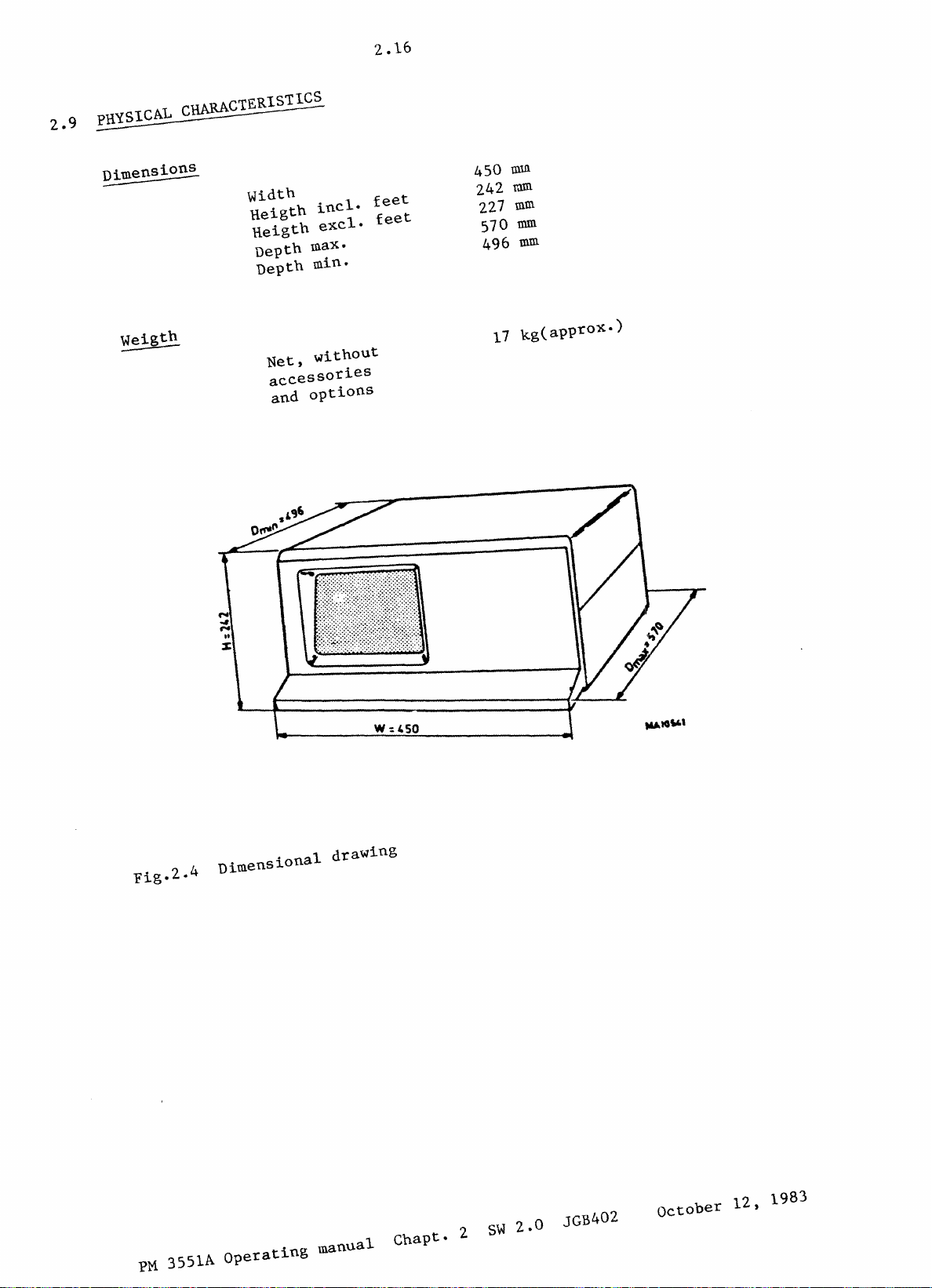
2.9
PHYSICAL
Dimensions
th
Weig
::..:::--=---
CHARACTERISTICS
Width
Reigth
Reigth
Depth
Depth
Net,
accessories
and
incl.
excl.
max.
min.
without
options
2.16
feet
feet
450
nnn.
242
mID
227
mm
570
rom
496
mID.
17
kg(approx.)
Fig.
PM
•
4
2
3551A
Dimensional
operating
drawing
manual
Chapt.
2
S~
2.0
JGB402
october
12,
1983
Page 22
2.17
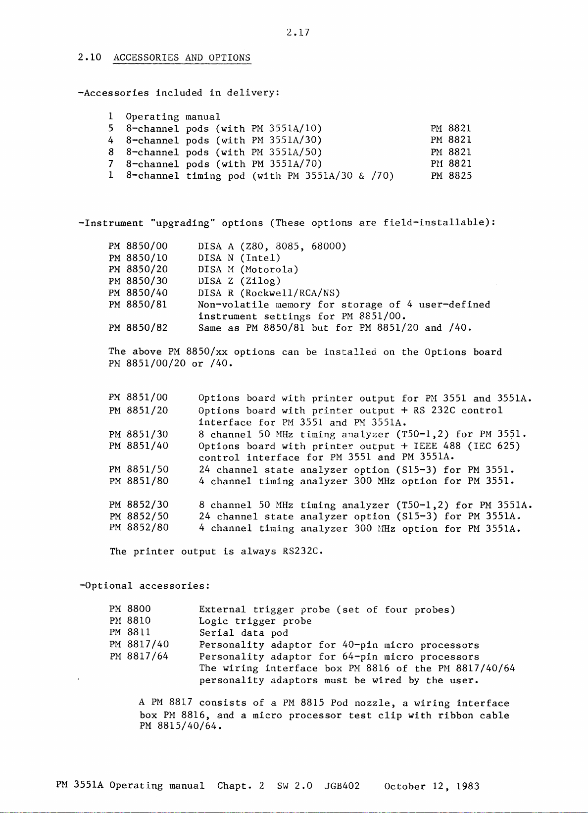
2.10
ACCESSORIES
-Accessories
1
Operating
5
8-channel
8-channel
4
8-channel
8
8-channel
7
1
8-channel
-Instrument
PM
8850/00
8850/10
PM
PM
8850/20
8850/30
PM
PM
8850/40
8850/81
PM
8850/82
PM
AND
included
manual
pods
pods
pods
pods
timing
"upgrading"
DISA
DISA N (Intel)
DISA
DISA Z (Zilog)
DISA
Non-volatile
instrument
Same
OPTIONS
in
delivery:
(with
(with
(with
(with
pod
options
A
(Z80,
H
(Motorola)
R
(Rockwell/RCA/NS)
as
PH
3551A/10)
PM
PH
3551A/50)
PM
(with
settings
PM
8850/81
3551A/30)
3551A/70)
PM
3551A/30 & /70)
(These
8085,
options
68000)
memory
but
for
for
are
storage
PM
8851/00.
for
PM
PM
8821
8821
PM
PH
8821
PH
8821
PM
8825
field-installable):
of 4 user-defined
8851/20
and
/40.
The
PH
PM
PM
PM
PM
PM
PM
PM
PM
PM
The
-Optional
PM
PH
PM
PM
PH
above
PM
8851/00/20
8851/00
8851/20
8851/30
8851/40
8851/50
8851/80
8852/30
8852/50
8852/80
printer
accessories:
8800
8810
8811
8817/40
8817/64
8850/xx
or
/40.
Options
Options
interface
channel
8
Options
control
24
4
channel
8
channel
24
4
channel
output
External
Logic
Serial
Personality
Personality
The
personality
options
board
board
board
interface
channel
channel
is
always
trigger
data
wiring
for
50
MHz
state
timing
50
MHz
state
timing
trigger
pod
adaptor
adaptor
interface
adaptors
can
be
with
with
PM
printer
printer
3551
timing
with
printer
for
analyzer
analyzer
timing
analyzer
analyzer
RS232C.
probe
probe
installed
and
analyzer
PM
3551
analyzer
(set
for
40-pin
for
64-pin
box
PM
must
output
output
PM
3551A.
output
and
option
300
MHz
option
300
HHz
of
8816
be
wired
on
the
Options
for
PM
3551
+
RS
232C
(T50-1,2)
+ IEEE 488 (IEC
PM
3551A.
(S15-3)
option
(T50-1,2)
(S15-3)
option
four
micro
micro
of
by
for
for
for
for
probes)
processors
processors
the
PM
the
user.
board
and
3551A.
control
for
PM
35~1.
625)
PM
3551.
PM
3551.
for
PM
3551A.
PM
3551A~
PM
3551A.
8817/40/64
PM
3551A
A
PM
box
PM
Operating
8817
PM
consists
8816,
8815/40/64.
manual
of a PM
and a micro
Chapt.
2
8815 Pod
processor
SW
2.0
test
JGB402
nozzle,
clip
a
wiring
with
October
ribbon
12,
interface
cable
1983
Page 23

The
following
disassembler
personality
of
the
indicated
2.18
adaptors
micro
are
specific
processors.
for
the
Adaptor
-----------------------------
PM
8817/10
PM
8817/12
8817/19
PM
PM
8817/20
8817/21
PM
PM
8817/22
PM
8817/23
PM
8817/24
8817/26
PM
PM
8817/27
PM
8817/28
Parts
of
accessories:
PM
8815/00
PM
8815/40
PM
8815/64
8816/40
PH
PM
8816/64
PH
8816/
••
Microprocessor
6800/02/08
NSC800
68000
8085
8048
Z80
Z8002
R6502/12
6809/E
8086/8088
8080
Set
of
5 Pod
40-pin
64-pin
Wiring
Wiring
Boxes
Wiring
micro
versions
clip
clip
interface
interface
PM
8816/40/64
interface
processors.
as
nozzles
with
with
the
PM
for
ribbon
ribbon
box
for
box
for
must
box
(pre-wired)
They
8817.
personality
cable.
cable.
40-pin
64~pin
be
wired
are
available
micro
micro
by
for
adaptor.
processors
processors
the
user.
c:ommonly
in
the
used
same
Ptv[
8819/00
PH
8819/10
PM
8819/20
8819/30
PM
8819/40
PM
Note:
For
more
Extension
coloured
54
35
measuring
mini
50
54
dualclips
coloured
information
kit
for
leads
clips
leads
refer
PM
for
for
to
8821
PM
PM
the
(leads,
8821
8825
chapter
clips
(length
(length
9.
and
26 cm)
12
cm)
nozzle)
PM
3551A
Operating
manual
Chapt.
2
SW
2.0
JGB402
October
12,
1983
Page 24
3.1
G
ENE
R A L D
IRE
C T
ION
S
PM
3551A
Operating
manual
Chapt.
3
SW
2.0
JGB403
October
12,
1983
Page 25

3
..
2
3.0
3.1
-
It
switching
-
This
IEC
Measuring
This
considered
GENERAL
WARNINGS
is
recommended
instrument
Publication
Manual
MAINS
220V
DIRECTIONS
AND
INFORMATION
on
the
has
348,
Instruments
contains
to
ensure
that
this
instrument.
been
Class
and
information
safe
FOR
sec.tion
desi.gned
1,
Safety
has
been
and
reliable
THE
USER
is
and
Requirements
supplied
and
warnings,
read
tested
operation
MAiNS
'lOV
completely
in
accordance
for
in
safe
all
of
of
before
Electronic
condition.
which
the
instrument.
with
must
be
r·-·_._·-·_·-·-o·,
r'-',i--,
!
=4:::.:---
i
j.
-
r
1.",..-0-"
PO~"
1If-r
~.m
00
Q~
tIn
'--------.,,....:;...-------_._j
Fig.
3.1
Connecting
SU"""y
pelt
I
220V
'\\
I \
~
~
Tl
I I
''I
MAINS
f'
-""
r··
..
..:.
..
~
\
\
\
l
I I
j
=.:,:;,·r~
T !
I
\
\
~
\.
.,
\
~
\
••
,._.,,_:~
for
220 V or
110
V
POW~_
5Uf'~,(
...
",.,.,
'lilt
',r.l<'-o--
Y1m~
mill
, 10V
range
mains
-_._--,
',\
'\
\
\
\
\
\
\
JoIIAiN~'
voltage.
PM
3551A
Operating
manual
Chapt.
3
SW
2.0
.JGB403
October
12,
1983
Page 26
3.3
Mains
Before
set
plate
the
Range
New
for
adapt
connecting
to
the
has
power
settings
instruments
the
country
Earthing
-
Before
switching
protective
•
via
the
identified
•
via
the
The
mains
with a protective
be
negated
conductor.
ion
correct
to
be removed
supply
are
are
of
earth
protective
by
the
earth
plug
by
wire
shall
the
Replacing
the
instrument
voltage
and
compartment
shown
in
shipped
destination.
on,
the
instrument
conductor
earth
symbol
in
the
only
earth
use
contact.
of
the
to
range.
it
can
are
set
figure
with
in
the
one
terminal
(+) .
three-core
be
inserted
an
extension
mains
plug
the
To
be
3.1.
of
at
The
mains
do
this,
seen
to
the
voltage
shall
the
be
following
the
mains
in a socket
protective
cord
is
at
supply,
the
if
some
relevant
range
connected
rear
of
cable.
without
the
user's
ensure
upper
cabinet
connections
voltage
setting
to
ways:
the
instrument,
outlet
action
shall
protective
own
that
of
range.
correct
a
provided
not
risk.
it
WARNING:
Any
outside
earth
dangerous.
instrument
condensation
therefore,
adhered
Cooling
-Take
care
obstructed.
instrument
-Do
not
use
Refer
Adjustmen~,
When
- The
before
live,
(except
expose
instrument
also
the
and
those
live
it
instrument
the
is
maintenance.
Capacitors
and
the
video
instrument
Any
adjustment,
under
voltage,
inevitable,
aware
of
the
interruption
the
terminal,
Intentional
is
that
to.
that
the
forced
Do
not
place
to
avoid
the
to:
~mintenance.
excessive
instrument
replacement
is
opening
to
which
parts.
shall
opened
inside
for
the
display
has
been
disconnected
repair
should
should
only
hazards
of
the
instrument,
is
likely
brought
may
cause a hazardous
the
earthing
air
any
instruments
when
of
parts
connected
of
the
covers
access
be
disconnected
any
adjustment,
instrument
unit)
or
be
may
maintenance
avoided
be
carried
involved.
protective
or
disconnection
to
render
interruption
from a cold
requirements
flow
through
heating-up.
the
built-in
and
repair
to
the
or
can
be
gained
from
(specially
still
from
be
all
of
as
far
out
conductor
the
is
discouraged.
to
a warm
condition.
the
instrument
or
papers
fans
mains,
the
all
repair,
terminals
removal
by
hand)
voltage
replacement
in
the
charged
voltage
the
instrument,
as
possible,
by a skilled
inside
of
the
instrument
environment,
Ensure,
are
strictly
on
the
are
not
of
parts
is
likely
sources
power
even
if
sources.
and,
person
or
protective
When
is
not
top
of
running.
may
be
to
or
supply
the
when
opened
if
who
is
an
the
unit
PM
3551A
Operating
manual
Chapt.
3
SW
2.0
JGB403
October
12,
1983
Page 27
-
Never
been
-
Ensure
specified
The
Haintenance
-
Cooling
Check
plate)
If
When
switched-off
use
is
prohibited.
necessary
the
remove a
that
of
the
vent
once a year.
filter
circuit-board
only
type
are
make-shift
holes
free
for
fuses
the
is
at
with
used
clogged
for
fuses
and
holes
or
least
the
one
the
replacement.
and
dust
(use
with
3.4
component
minute.
required
the
short-circuiting
filter
pressurized
dust,
it
until
rated
(located
air).
must
be
the
current
in
cleaned.
instrument
and
of
of
fuse
the
bottom
has
the
holders
Older
We
mesh
-
Cleaning
cabinet-plates
with
white
Do
Lithium
The
instruments
recommend you
filter.
If
necessary,
some
spirit.
not
battery
lithium
assembly
This
battery
Bad
battery
INVALID
A
battery
Service
Note
be
that
thrown
to
the
may
water
use
abbresive
battery
battery
above
when
in
Organization).
this
in
and
back-up
located
the
requires
condition
selecting
bad
battery
open
are
provided
have
VDU
be
motherboard.
condition
fire.
this
glass
cleaned
common
cleaning
instrument
on
no
is
a
may
with a plastic
filter
surface,
with a soft
houshold
pads
setting
the
lower
special
generally
saved
or
must
never
replaced
the
cleansing,
or
materials.
memory
board
maintenance.
indicated
stored
be
replaced
be
opened,
fiber
by
front
pad,
is
of
the
by
setting.
(call
nor
dust.
the
panel,
cloth,
or
some
energized
....
the
your
short-circuited,
filter.
standard
and
or
cotton-wool
alcohol
sandwich
message
local
metal
the
by a
....
-print
SETTING
Philips
or
3,6V
nor
- Whenever
- The
- The
PH
3551A
Defects
instrument
further
protection
the
instrument:
• shows
•
fails
•
has
been
conditions.
•
has
been
Diagnostic
instrument
progrannn
Operating
and
abnormal
it
is
should
operation.
visible
to
perform
subjected
subjected
self
as
an
manual
likely
be
is
likely
damage.
its
test
is
provided
aid
to
stresses
that
the
made
to
to
Chapt.
inoperative
to
have
intended
prolonged
severe
with a comprehensive
fault-finding.
3
protection
and
been
functions.
stresses
SW
impaired
storage
2.0
has
secured
under
during
JGB403
been
impaired,
against
if,
for
unfavourable
transport.
diagnostic
October
the
any
example,
self
12,
test
1983
Page 28

3.5
This
is
switched-on
front
Pressing
returns
More
Turning
For
- The
- Check
- The
programm
kept
panel
information
SERVICE
connecting
instrument
switch
initial
depressed,
(or
key
the
QUIT-soft
the
instrument
MANUAL
power
at
the
that
the
is
started
while
if
the
internal
depressed).
key,
to
about
of
this
on
and
is
rear
built-in
configuration
the
instrument.
detailed
turned
of
if
any-one
the
which
the
diagnostis
preparation
on
the
instrument
fans
menu
mains
reset
normal
by
are
of
the
voltage
button
is
shown
operation
programm
switching
to
running.
appears
for
on
keys
of
in
the
ON.
on
the
is
pressed
the
programme
is
use
refer
power
See
the
display.
the
front-panel
instrument
with
diagnostic
given
also
in
to
chapter
ON/OFF
figure
is
a
test
the
6.
3.3
PM
3551A
Operating
manual
Chapt.
3
SW
2.0
JGB403
October
12,
1983
Page 29

3.6
3.2
sockets
as
normally
3.2.1
r
DESCRIPTION
This
section
the
controls
FRO
PM 3551
on
be
logic
HEADING
the
used
OF
describes
instrument.
in
by
N T
PAN
_nOilyzer
(6
LINES)
those
-----------------------_.-
(16
KEY
FIELD
soft
LINES)
DODD
,
keys
DATA
FIELD
-------------------------
I
CJ
,
SOFT
CJCJCl
CONTROLS,
the
operation
The
areas
the
operator.
E L
(211NES)
CONNECTORS
and
front
are
explained
.....---
"
OAIO
panel's
CUl!~OA
IN
H[AO,,,,,'
0
CU~OA
IN
Ft£lO
0 D 0 0
~OWER
~J
0
--
-
--
~
,
o-t-o
mOve
l'
keys
D--1
AND
DISPLAY
function
functional
in
.--
10
lfi
~
of
the
sequence
MENU
J1Jll
0
(ON".
EJ
lRIC,
DATA
CJ
CU"'PIt.~E
heK
..
•
0
I
0
0 +
0 0
I
0
0
[]
•
. \
controls
areas
ACOUI
~'111ON
SIAAI
AUTO
SOK.I.[
D D
~)
lOAQ
CO",'O'
OVWP
o D
DATA
lIS
I
""a.PH
11£<
C'-ENI
0
CJ
G;
"0"'
oGa
pOid
...
eys
(
0
0 0
Cl
,
0 0
0 0 0
as
they
CON T ROL
DISPLAY
[
,
0
and
510"
CJ
~tN'
CJ
T_
.. I illiG
0
COO'Pt.R[
0
TRI(;W
0
r
0
•
0
DUllE
0
well
would
""
I
...
-c'l
J.
PM
CURSOR
CURSOR
CURSOR
POWER
3551A
Fig.
3.2
position
IN
HEADING
IN
DATA
The
cursor
characters.
combined
The
cursor
(lamp)
Operating
Front
panel
area
FIELD
can
be
located
The
cursor
with a blinking
can
be
moved
Indicates
(The
manual
main
that
switch
Chapt.
This
button
heading
This
button
data
on
field.
one
generally
character.
with
the
the
and
3
SW
forces
(this
forces
character
consists
four
instrument
fuses
2.0
JGB403
the
is
the
the
only,
of a reverse
move
keys.
is
are
located
cursor
condensed
cursor
or
on a
switched-on.
at
the
October
into
menu).
into
group
video
rear
12,
the
the
of
block
panel).
1983
Page 30

MENU
area
FULL
CONFIG
TRIG
DATA
COHPARE
OPTION
ACQUISITION
START
START
SINGLE
AUTO
STOP
I/O
CONTROL
LOAD
DUMP
PRINT
DATA
DISPLAY
Selects
Selects
Selects
(When
selected,
timing
Selects
Selects
Selects
CONTROL
Starts
Starts
Stops
area
(only
The
device,
The
device
The
area
a
the
the
both
trigger
the
the
the
area
a
single
automatic
data
active
analyzer
or
analyzer
or
analyzer
Full
menu
Configuration
Trigger
the
State-
this
key
menus)
Data
menu
Compare menu
Options
sftot
restart
acquisition
if
an
memory
controller.
memory
controller.
memory
(refer
menu
and
gives
menu
data
(repetitive)
in
interface
is
loaded
contents
contents
to
Menu
Description).
menu
the
Timing
alternatively
acquisition
single,
as
option
with
is
transferred
is
transferred
analyzers
action.
data
well
has
data
have
the
state-
and
acquisition.
as
in
auto
been
installed)
from a storage
to a storage
to a printer.
been
the
mode.
LIST
GRAPH
TIMING
CURRENT
REF
COMPARE
STORE
area
SETTING
DATA
TRIGW
SOFTKEYS
There
Each
the
are 8 softkeys,
active
key. A disabled
Memory
Memory
LIST
Memory
This
The
The
The
of
The
(only
The
the
The
displayed
trigger
softkey
contents
contents
and
contents
applies
contents
contents
contents
the
reference
settings
if
contents
reference
cursor
word
located
function
softkey
GRAPH
only
of
of
of
of
an
option
of
word
data
in
is
function
is
displayed
is
displayed
display
is
displayed
to
the
the
the
memory
the
the
memory.
(which
list)
the
directly
displayed
apply
the
Timing
current
reference
current
are
analyzer
PM
8850/80
current
is
the
is
copied
trigger
underneath
in
is
presented
in a list
in a graph
only
as
to
blockform
Analyzer.
memory
is
memory
memory
and
compared.
are
stored
has
been
memory
is
uppermost
into
menu.
the
inverse
in
format.
format.
the
State
displayed.
is
displayed.
the
installed).
copied
word
the
cursored
display.
video,
normal
signals
contents
into
of
just
video.
Analyzer.
the
above
PM
3551A
Operating
manual
Chapt.
3
SW
2.0
JGB403
October
12,
1983
Page 31

MOVE
KEYS
(scroll,
3.8
shift)
These
-Positioning
-Scrolling
HEX
The
DELETE
field.
KEYS
hex
X
keys
keys
=
don't
decimal
deletes
have
of
the
(O---F)
two
the
data
care
sign
full
functions:
cursor
list,
permit
numerical
in
or
the
menus,
horizontal
hexadecimal
input
or
shift
input
in
the
of
for
the
the
label
timing
various
line
in
the
display
settings.
data
window.
PM
3551A
Operating
manual
Chapt.
3
SW
2.0
JGB403
October
12,
1983
Page 32

3.9
3.2.2
REA
R
PAN
E L
o
".T
®
'AT
@
co
.. P
y~
Fig.
Seen
3.3
from
indication:
-S15-1
8
S15-2
indicates
-T50-1+2
!
indicates
-OPT-X
(instructions
manual)
On
above
State
On
S15-1
Pod
#2,
Pod
#O
•••
(two
of
On
815-3
All
these
Rear
the
rear,
S15-3
State
(both
Timing
mentioned
section
and
S15-2
Pod #3
Pod #3
the
qualifiers
the
input
inputs
panel
only
and
are
are
you
find
(the
latter
Analyzer
in
versions
Analyzer
for
field.
units
the
Pod
data
you
input
#Q.
inputs;
may
connectors
15
pins
from
only
p.c.
/30
p.c.
fitting
will
connectors
be
used
are
input
left
in
boards.
and
boards.
find
Pod
#Q
as
data
located
connectors
to
right
versions
/70)
are
given
the
following:
are
is
input
channels).
for
the
:ocated
Pod
to
following
/50
and
in
chapter
for
for
clocks
#4,
Pod #5
connect
/70)
Pod
PM
unit
10
of
#0,
and
and
8821
this
Pod
#1,
qualifiers
Pod
#6.
Pods.
PM
3551A
On
815-1
-MATCH
-RUN
OUT
OUT
acqusition,
Operating
three
delivers
is
delivering
i.e.
BNC
connectors
an
between
manual
active
an
active
start
Chapt.
are
high
and
3
present:
TTL
high
stop
SW
2.0
signal
TTL
signal
(final
JGB403
if a trigger
during
triggering).
October
data
word
12,
occurs.
1983
Page 33

3.10
-TRIG IN
signal.
is
specified
Timing
On
T50-1+2
-POD
#T
-MATCH
the
time
(are)
-TRIG IN
with
an
The
external
selected
An
unused
Pod #0
There
are
Analyzer
This
depends
the
instrument
rear
panel
In
the
Pod T
not
In
and
of
activated.
the
Pod T
features
The
external
as
section
the
following
25
pins
input
OUT
BNC
connector,
that
the
present.
BNC
connector
external
signal
between
input
and
Pod
#T
two
possibilities
input.
on
the
at
by
e.g.
'in'-position
the
Timing
'out'-position
can
be
triggering
signal
TTL
level
connector
selected
signal.
must
-3V
and
is
regarded
relation
position
unit
a
ball
Pod
Analyzer.
there
used
separately.
must
at
connectors
delivering
trigger
features
be
+12V
to
S15-2.
point
110
of
is
of
the
data
be
fed
the
probe
are
for 8 timing
a
word
triggering
fed
via
at
the
as a "0".
apply
of
the
switch
The
switch
pen
or a small
the
State
The Pod #0
no
interconnection
acquisition
via
tip.
present:
high
is
the
PM
probe
the
can
Analyzer
input
the
channels
active
true
of
the
8800
tip.
Pod #0
which
be
with
PH
8800
(via
EeL
signal
and
clock
data
probe
acquisition
and
signals
is
present
manipulated
screw
of
driver.
is
interconnected
the
State
between
an
probe
Pod
pulse(s)
can
to
the
at
through
Analyzer
both
external
and
PM
8825).
during
be
State
the
Pods;
is
rear
the
with
is
Pod #0
of
General
-Mains
-Two
-Mains
-Separate
section
switch
fuses 4 Amps
cord
gnd
-ADJUST VEIL
display.
-COMP
an
VIDEO
external
pulses.
Brightness
At
the
LEFT
-Screw
driver
(delayed
provided
connection
allows
BNC
output
video
display.
adjustment
HAND
SIDE
adjustment
action)
with
gnd
brightness
giving a video
This
of
the
for
for
wire
adjustment
signal
instrument;
brightness
both
signal
includes
of
of
the
the
(1.25
the
110V
and
veil
Vp-p)
line-
display.
in
and
220V
the
to
frame
ranges.
timing
connect
sync
PM
3551A
Operating
manual
Chapt.
3
SW
2.0
JGB403
October
12,
1983
Page 34

4.1
DES
C
RIP
T
ION
0 F
THE
MEN
U S
PM
3551A
Operating
manual
Chapt.
4
SW
2.0
JGB404
October
12,
1983
Page 35

4.2
4
A menu
which
There
A
full
area.
A
condensed
for a display
The
-Configuration
-Trigger
-Trigger
-Selective
-Compare
-Options
For
Changes
condensed
corresponding
DESCRIPTION
WHAT
....
S A
--------------
is a survey
apply
are
menu
following
each
HENU?
to a certain
full
states
menu
field
menus
menu
menu
menu
menu
in a full
data
full
menu;
state
timing
menu a
full
OF
THE
of
menus
menu
acquisition
changes
and
full
states
for
are
section
section
condensed
menu
menu.
MENUS
specific
main
condensed
detailed
just
data.
selectable:
are
automatically
in
condensed
functions,
analyzer
the
menu
menu
mode
menus.
information
most
relevant
is
available
menus
copied
parameters
or
function.
and
requires
information
(options
in
are
not
and
values
the
corresponding
all
copied
the
leaving
menu
whole
in
display
room
excepted).
the
Selectable
softkeys.
The
cursor,
can
be
positioned
Note
By
When
stored
First
this
that
pressing
you
in a battery
chapter
we
functions
which
with
switch-off
discuss
the
show
each
relevant
puts
with
the
the
are
indicated
the
selected
the
four
new
cursor
softkey
the
instrum€~nt,
back-up
default
full
memory. The
values
menus.
by
funetion
arrow
position,
the
function
all
of
the
cursor
or
keys.
the
softkey
settings
configuration
the
settings
and
value
or
parameter
in
the
labels
in
inversed
functions
the
menus
menu
after
above
video,
may
change.
is
selected.
remain
photographs
switching
the
in
on.
PM
3551A
Operating
manual
Chapt.
4
SW
2.0
JGB404
October
12,
1983
Page 36

4.1
4.3
'~.1.1
General
In
59
state
are
Press
(after
Configuration
Note
up
memory, when
In
CONFIGURATION
information
this
chapter
channels
not
applicable
the
FULL-
switching-on
Menu)
that
the
the
following
current
MODE
CLOCKS CLOCKS
DATA
INPUT
HENU
we
discuss
and
in
and
the
the
the
mains
we
discuss
59
CLKO=
CLK1::
CLK2=~
THRESHOLD
the
menus
8
timing
your
CONFIG
channels,
Instrument~
key
instrument
instrument
voltage
the
CONrIGURAT!O~
CHANNEL
STATE
UITH 8 TIMING
QUALIFIERS
AND
TRUE
TRUE
CLOCKS
J
t
in
display
setting
is
lJlenUS
MENU
US.
LABELS
of
an
Instrument
so
skip
the
~lliNU
shows
is
always
swi~ched
as
in
the
90
91
Q2
93
X X X X
X X X X
area.
off.
initial
provided
numbers
always
saved
with
or
functions
the
initial
in a battery
setting.
35
full
or
which
back-
POD-9
POD#6
TTL TTL TTL TTL
i'
o
AAAAAAAAAAA
1
___________
CLK
INT:
FORHAT~~
LOGIC
POS
BASE
HEX HEX
i
-.u.
Fig.
CLOCI<S
__
4.1
PODMS
if'
BBBBBBBBBBBBBBBB
EEEEEEEEEEEEEEEE
POS
POS
POS
HEX
HEX HEX
__
Full
Configuration
POD~4
POD~3
iii
CCCCCCCCCCCCCCCC
EFFFFrrrrFFFFrrr
POS
POS
TTL
POS
POD~2
TTL
iii
POD#1
TTL TTL
DDDDDDDJDDDDDDDD
GGGGGGGGGGGGGGGG
HEX HEX
i
,r-------llQUALIFIERS,------
TRUE
FALSE
1 0
Menu
POD~O
I
TTTTTTTT
PH
3551A
Operating
manual
Chapt.
4
SW
2.0
JGB404
October
12,
1983
Page 37

MODE
The
following
COMBI
This
both
Each
the
Start
modes
mode
the
State
Analyzer
other
data
are
selectable:
applies
Analyzer
is
Analyzer
acquisition
4.4
typically
capable
(LSA
and
of
enables
is
common
for
combinative
the
Timing
enabling
LTA,
for
Analyzer.
the
triggering
or
LSA
both
Analyzers.
use
waits
of
for
of
LTA).
STATE
TIME
SYNCED
STORED
SAVED
CLOCKS
In
this
mode
Now
you
have a Timing
The
Timing
State
ENABLE
Both
is
You
synchronization
Samples
the
If
is
instrument
Pressing
as
If
switching-off,
when
Analyzer.
Analyzers
obtained
will
timing
the
enabled.
it
the
the
Analyzer
LTA
command.
miss
captured
diagram.
non-volatile
settings.
this
was when
instrument
saved
your
The
work on
between
two
purposes
with
You
can
key
the
the
key
instrument
Analyzer
will
Timing
their
both
timing
the
memory PM8850/80
recall
Refer
recalls
instrument
setting
message
is
pressed.
is a State
only
now
run
Analyzer
own
captured
channels;
between
State
one
out
to
page
the
complete
was
was
not
INVALID
Analyzer
(max 8
'time-referenced'
being
sample
data.
they
both
analyzers.
Analyzer
is
of
four
4.6.
switched
correct
SETTING
channels).
triggered
clock,
are
are
built-in,
stored
instrument
off.
at
will
but
used
marked
the
be
only.
with
by
reference
for
in
this
complete
setting
moment
shown
the
the
key
of
Allows
Also
Note
In
In
following
A
level
The
You
VAR
key
the
that
DATA
this
threshold
the
THRESHOLD
correct
detection
threshold
can
is
pad.
you
to
select
corresponding
at
least
INPUT
35-channel
select
any
field
voltage
two
threshold
value
THRESHOLD
you
fields.
voltage
TTL, ECL,
the
one
can
select
per
Pod.
state
voltage
of
the
is
between-3V
active
qualifiers
clock
AND
input
must
CLOCKS
labels
analyzer
is
signals.
selectable
or
VAR.
and
clocks
and
be
selected.
VS.
LABELS
per
version
important
per
+12V,
and
their
active
this
to
Pod.
and
clock-edges.
polarity
clock,
field
obtain
must
be
consists
a
entered
can
be
and
the
reliable
selected.
logic
of
logic
via
the
the
HEX
PM
3551A
Operating
manual
Chapt.
4
SW
2.0
JGB404
October
12,
1983
Page 38

LABELING
4.5
This
function
labels
Available
Channels
same
label.
Labels
display
Certain
-Labels
-The
same
provided
Note
that
discussed
Timing
number.
LOGIC
This
Logic
Often
'0'
An
function
applies
positive
is a low
exception
and a '0'
In
this
systems
remain
labels
of
adjacent
may
be
format
rules
must
label
it
the
in
channels
If
the
is a high
case
signals
allows
present
are
allocated
(see
apply
be
allocated
can
covers
labeling
the
next
have
capture
and
to
the
logic
voltage.
is
e.g.
pressing
being
you
A---G.
Pods
the
to
be
the
basically
the
logic
is
IEEE/IEC
voltage.
to
label
in
all
further
can
in
any
FOR}~T
the
allocation
on a contiguous
allocated
same
is
channel
also
points.
mode
BASE
has
(see
(polarity)
used,
the
NEG
displayed
be
grouped
order
line)
to
related
label
been
point
where
bus
soft
as
groups
displays.
in
is
of
two
inputs.
T
selected
'1'
logic,
key
l's.
this
always
or
to
(for
6)
of
is
will
of
input
together
field,
in
labels:
block
more
the
basis.
clock
base-selection
timing)
the
one
have a combined
the
input
a
high
where
a
'1'
result
channels;
by
giving
but
the
alphabetical
sources,
with
a
label
C
signals.
voltage,
is
a
in
the
the
them
resulted
which
channel
applies.
cursor.
and
low
voltage
active
same
the
order.
is
low
BASE
The
base
represented.
The
base
The
base
Generally
E.g.
if
octal
in a group
The
value
logic,
selected
is
the
can
be
selection
a
specific
base
of
three
of
non-activated
numerical
binary,
is
related
number
has
channels
threshold,
base,
hexadecimal,
to
of
been
selected,
(though
bits
etc.
or
the
octal,
the
above
bits
is
the
other
in a group
code
in
decimal
channel-labeling.
used
per
labeling
numbers
depends
which
base
the
or
setting.
must
are
on
data
ASCII7.
be
logically
allowed).
the
selected
will
be
PM
3551A
Operating
manual
Chapt.
4
SW
2.0
JGB404
October
12,
1983
Page 39

The
STORED
non-volatile
1--4.
The
SAVED
switched-off
up
memory).
After
switching-on,
default
If
your
following
-How
to
STORE
softkey
memory
softkey
the
setting.
instrument
STORE
a SETTING.
allows
(PM
recalls
instrument
the
is
not
and
RECALL
4.6
selection
8850/80/82).
the
setting
before
instrument
equiped
functi.ons.
of
one
out
of
The
settings
as
it
was
at
(this
IDenus
is
are
retained
always
with a non-volatile
four
settings
are
stored
the
moment
in a battery
in
the
memory,
under
you
initial
skip
of
the
label
back-
the
Press
the
blinking).
The
message
by
the
NO
Enter
is
Only
disturb
message
Note
to
-How
Select
Press
The
the
started,
switching-off
the
STORED
that
store
to
RECALL a SETTING
the
the
softkey
--#1-- --#2--
Press
If
this
the
erroneously
by
pressing
Store
ENTER
FREE
label
and
setting
it
takes
one
complete
full
STORED
functions
relevant
a wrong
Setting
LABEL
LABELS
nr
you
ON
LB X appears
message).
via
the
can
the
mains
to
be
key
NR
continue
approx.
setting.
configuration
softkey.
are
--#3--
label
--#4--
number
label
the
NONE
:in
appears
hex
voltage
stored.
10
Sec.
menu.
now:
number
softkey.
the
STORE
on
keypad.
with
At
(X
is
(typ.)
Cursor
-ENTER
softkey
softkey
field
the
After
the
during
the
end
the
entered
-NONE-
and
(the
screen
(generally
entering,
operation.
the
store
of
the
number).
up
to 1 Min.
on
configuration
------
press
has
the
been
cursor
the
a.ction
store
20
------
ENTER
pressed,
stops
preceeded
store
will
cycle
Sec.
(max.)
mode.
softkey.
correct
action
the
PM
3551A
Experience
setting
Operating
details
manual
has
Chapt.
proven
of
4
that
each
SW
it
stored
2.0
is
quit
setting
JGB404
useful
for
October
to
note
yourself.
12,
the
1983
Page 40

4.7
4.1.2
TRIGGER
Press
Note
One
In
the
that
for
the
TRIG
State
MENU
the
FULL-
in
versions
the
state
COMBI-mode,
key.
trigger
TRIGGER
1
FIND
2
FWD
3
FIND
FIND
4
5
END.
ON
UOPD 1 DELAY = 100
UORD
2
UORD
IF
3
UORD 3 THEN
UORD 5 DELAY : 1000
HATCH
and
the
analyzer
these
menu
STATt
SEQUENCE:
OR
OUT
TRUE
4
STEP 1 ELSE
ON
UORDS:
TRIG
PM
3551A/30/70
and
menus
TRIGGER
MENU
STATES
STEP
STATES
5
key
or
4
or
in
one
are
elK
CLK
0
0+1
the
MENU
there
for
timing
alternately
area.
are
analyzer.
two
trigger
displayed
menus.
by
pressing
This
menu
un
eLK
1 0
XXX
2 0
7£6
3 1
~
1
5
0
7E6
____
Fig.
is
4.2
divided
**STATE
TRIGGER
SEQUENCE
XXXX
xxxx
021C
4COO
021C
4412
State
in 3 main
TRIGGER
ON
SEQUENCE
"
I
II
XXXX
22Fr
10Fr
2
--
Trigger
00438
4C66
00438
3A67
--------
Menu
fields,
MENU**
TRUE,
OOFr
F4FF
OR
Q F
X T
x T
x T
X T
x T
from
top
-BREAK
to
bottom:
PM
3551A
TRIGGER-\vORDS
Operating
manual
Chapt.
4
SW
2.0
JGB404
October
12,
1983
Page 41

4.8
TRIGGER
1.Trigger
2.Trigger
SEQUENCE
In
This
The
You
Note
acquisitionFor
to
Note
analyzerTwo
-Enable
-Wait
ON
SEQUENCE
In
this
specific
A
number
sequence
this
field
list
various
can
enter
that
detailed
chapter:
that
functions
LTA
for
TRUE,
on
sequence
mode a number
on
is
order
of
is
divided
trigger
to
sequence
conditions
broken
you
can
words
trigger
these
and
trigger
the
information
in
the
Combi
and
the
Timing
are
possible:
The
State
of
the
LTA
The
State
After
analyzer,
is
enabled.
OR
-BREAK
true
of
obtain
break
must
triggering
write
in
steps,
are
words,
words
compare
on
mode
analyzer
analyzer
Timing
analyzer
triggering
the
conditions
triggering.
be
sequentially
occurs.
the
trigger
numbered
labelled
delays,
can
also
menu.
the
trigger
linkage
triggering.
analyzer.
(incl.
next
must
sequence
from 1 onwards.
as
if-then-else
be
sequence
can
be
enables
starts
the
trigger
be
1--6
used
made
triggering
the
Timing
delays)
word
fullfilled
fullfilled;
order.
(or
7).,
conditions
in
the
possibilities
between
analyzer.
of
of
the
in
if
selective
the
the
Timing
State
a
the
and
refer
State-
analyzer
so
data
on.
TRIGGER
Trigger
As
in
Note
hexadecimal
Words
also
trigger
At
-the
-the
-the
Two
They
-an
-a
-a
In
sequence;
WORDS
soon
th~
that
1--6
be
the
selective
windows.
counter,
compare
block
more
can
occurences
word
word
addition
words
as a word
'don't
the-trigger
form.
are
used
step
same
by a delay
were
time,
function,
to
be
compared.
words,
be
used
to
be
to
be
word B can
in
this
are
initiated
has
careA-form
the
principal
it
is
each
data
acquisition,
to
define
word A and
as:
delay
counter
captured
counted
case
in
been
words
selected
in
can
the
counter
used
of
the
start
to
define
word
by
selective
by
the
also
be
word B is
the
trigger
only
trigger
(delay
as
the
words
to
and
the
B,
in
every
counter
used
labelled
trigger
in
the
word
be
set
words.
on
trigger
1--6
may
define
stop
of
start
are
available:
trigger
data
acquisition
as a trigger
sequence
sequence
list.
in
binary-,
Each
of
occurences)
word.
be
used
start
the
and
and
counter
stop
step
word
as
word
7.
list.'
list,
these
in
with:
stop
window.
of
the
in
it
octal-
words
the
of
the
appears
or
can
sample
memory
trigger
PM
355lA
Operating
manual
Chapt.
4
SW
2.0
JGB404
October
12,
1983
Page 42

In
the
WD
In
WD
CLK
<Labels>
Q
is
external
F
is
qualifier.
In
the
are
initiated
heading
CLK
which:
is
trigger
is
the
the
the
trigger
of
the
<LABELS>
word
clock
is
the
indication
polarity
trigger
definition
word
in
the
trigger
Q F
number.
source
of
the
edge
(true
list
trigger
for
external
signal.
or
you
4.9
word
of
find
sequence
that
the
See
false)
list
trigger
the
you
selected
trigger
below.
of
the
trigger
list.
find:
word.
channel
word
trigger
words
labels.
qualifier,
word
as
soon
or
with
as
the
they
Note
are
The
Q
signal,
the
Note
as
the
that
enterend
trigger
Some
DELAYED
trigg~rqllalifier.details.
is
the
and
State
that
they
have
qualifier
clock
word
Jxternal
must
Analyzer
this
EDGE
--1-- --1--
Note
Logic
Pods
The Not
may
that
(PM
be a TTL
the
Probe
8821).
Delayed
PM
numbers,
via
the
itself
be
signal
been
of
the
Delayed
8800.
functions
signal
qualifiers,
softkeys.
is
trigger
applied
(S15.1).
controls
specified.
trigger
DELAYED
--1--
Edge-
These
applied
entered
word
LEVEL
qualifier",
to
the
all
With
word,
NOT
--0--
and
Delayed
functions
apply
to
via a coax.
and
via
the
TRIG
trigger
the
control
the
soft
DELAYED
--H--
compensate
the
PM
the
hex
or
IN
connector
word
key
Level
8810
cable.
True
or
keyboard.
the
external
qualifiers
cursor
labels
--L--
functions
the
Trigger
False
trigger
at
the
positioned
are:
--x--
apply
delay
of
Probe,
condition
rear
of
as
far
on
to
the
the
data
or
it
edge
PM
3551A
Delayed-
Note
qualifier
rest
be
qualifier
Operating
that
of
selected
and
edge
input
the
and
manual
Not
triggering
edge
trigger
once
two
Delayed
signal
sequence.
in
the
or
more
Chapt.
qualifier
works
has
trigger
level
4
SW
functions
as a latch
passed,
Accordingly,
sequence.
qualifiers
2.0
JGB404
do
not
function.
it
remains
the
edge
Combinations
are
possible.
October
work
Once
latched
trigger
of
12,
together.
the
selected
for
the
can
one
edge
1983
only
Page 43

4.10
Trigger
In
the
following
functions.
softkey.
For
more
TRUE
BREAK
selects
Sequence
conditions.
Sequence
which
In
set.
refers
the
Note
is
the
sequence
Each
(with a GOTO
sequence.
that
sequence
or
WRD2
Sequence
In
information
the
main
TRUE
BREAK
not
trigger
this
means
means
in
the
break
Softkeys
we
give
example
on
trigger
triggering
triggering"is
right
trigger
word
Functions
an
we
trigger
mode.
sequence.
may
be
example
statement)
in
the
following
example,
WRD3-)WRD4-)WRD5-)WRD3
are
sampled
with
another
with
succesively
functions
after
fulfilment
obtained
mode,
with
one
or
without
to a step
if
also
triggering
clock).
some
pressed
refer
trigger
earlier
WRD1
Refer
principal
the
to
chapter.
of,
all
if a trigger
or
word
delay,
WRD2
in
per
the
the
is
occurs
to
Fig.
trigger
left-most
5.2.
trigger
word
step
last
list
found
(also
4.3.
is
can
step
to
in
if
found
be
obtain
the
WRD1
1
FIND
WORD
2
FIND
3
4
FIND
5
6
Fig.
If
FIND
FIND
GOTO
4.3
the
WORD
WORD
WORD
WORD
STEP
initial
proceed.
-------FIND
1
The
Find
1
1-)2
1
OR
2
1
2
3
4
5
3
Example
setting
WORD------
1-)2
Word
find
find
find
keys
word
word
word 1
of
1
trigger
TRUE
OR
2
control
1
1,
immediately
sample;
or
W,
on
is
the
word 2
ws
HA107\,
sequence
desired,
trigger
followed
no
matter
(this
a
Boolean
find
word 1
press
word
which
can
relation:
break.
by word 2
be:
or
or a conditional
with
If
----
Then
the
-)
selection
clock).
find
word
relation
----
1
'-
or
~)<ey
END
in
this
(next
2,
when
stateHlent.
to
EDIT
step.
clock
combined
PM
3551A
Operating
manual
Chapt.
4
SW
2.0
JGB404
Oc
tobe"r
12,
1983
Page 44

4.11
END
EDIT The
DELAY
DELAY
ENABLE/WAIT
-ENABLE
-WAIT
puts
trigger
The
sequence
downwards,
If
the
After
key
LTA
LTA
the
END
this
decimal
entering
to
obtain
LTA
The
Timing
as
The
by
END
statement
output
statement
list
permitting
key
is
keys
the
is
the
Logic
Analyzer.
well
as
triggering
triggering
in
signal(s)
is
is
------LTA----ENABLE
pressed,
of
the
delay
unity
trigger-linkage
State
in
can
not
selectable
aborted
easy
the
the
hex
value
of
Analyzer
This
the
SYNC
of
the
of
the
the
next
be
selected,
from
modification.
WAIT
delay
key
delay
is
Logic
Timing
the
value
pad.
use
being
function.
enables
selectable
mode.
State
Analyzer.
step,
in
the
cursor
NEXT
the
appropriate
selected.
triggering
after
if
required.
first
position
can
be
in
the
Analyzer
which
step.
entered
soft
of
COMBI-
is
the
via
key
the
enabled
NEXT
STATES
If
STATES
OCCUR
USEC
----------------------ON
initiates
DELAY
MSEC
OCCUR
has
been
The
delay
The
clocks
combination
The
delay
This
itself,
SEC
Provide
the
USEC
selected
word
or
a
next
is
activated
is
can
word
delay
step
HSEC
these
a number
of
these
by
occurances
be
the
A.
in
in
the
SEC
softkey
of
state
in
the
clocks
same word
time.
(0--999
sequence.
configuration
can
(0--65535)
0--65
CLOCKS--------------------------
functions
clocks
be
specified.
as
used
for
usec
for
sec.)
(0--65535).
of a specific
in
o 1 2 0+1 0+2 1+2 0+1+2
become
menu
the
and
msec;
available.
or
a
trigger
word.
step
PM
3551A
Here
states
Note
Operating
you
can
delay.
that
manual
the
Chapt.
select
'+'
the
sign
4
clock(s)
means a
SW
2.0
related
logic
JG13404
'OR'.
to
the
October
earlier
12,
selected
1983
Page 45

4.12
--------IF
2
Gives
of
If
just
-IN-
DELAY
Here
The
selected
delay.
soft
prompt
to
'IF
number
WORD---------
2-)3
two
key
have a simple
-AT-DELAY
you
above
key
which
•••
THEN'
2
the
possibility
words,
NEXT
can
trigger
to
Pressing
text,
'THEN
we
via
the
is
be
require
condition
OR
3
combined
pressed
form
extend
word(s),
found
either
being
STEP'.
hex
pad
to
check
with
the
next
of
delay.
the
trigger
or
during
of
these,
entered
Following
the
trigger
is
meet.
the
soft
for
1,
the
delay
trigger
delay
combination
the
delay,
results
into
the
this
sequence
Upon
keys
we
NEXT
or 2 or
function.
step
function.
or
in
trigger
must
to
entering
respond
of
at
the
enter
brancg
an
immediate
is
initiated,
words
the:
end
appropriate
sequence
the
entering
with
the
can
be
of
plus
step
to,
if
this
following:
the
number
the
follow
and
we
the
step
ELSE
STEP
Up
Try
If
the
the
instrument
fulfilled,
step
which
to
other
number.
'ELSE STEP'
now
we
trigger
NEXT
the
the
trigger
completed
key
is
assumes
trigger
Should
key
enables
functions
pressed,
that,
sequence
we
not
free
sequence
an
example
for
a new
if
the
should
require
definition
should
of a rather
your
self.
step
is
'IF
•••
continue
this,
of
continue.
NEXT
generated.
THEN'
then
use
the
step
extended
In
condition
from
this
of
the
number
trigger
addition
is
not
new
at
step.
PM
3551A
Operating
manual
Chapt.
4
SW
2.0
JGB404
October
12,
1983
Page 46

4.13
Timing
7=CLK
Iib1BIIID!II
trigger
TRIGG£R~QDE
TRIGGER
TIME
DELAt
FINAL
DELAt
T
IMUIG
OCCURS
t:HAtitiEL
6=5T
menu
TIt1U1G
UORD
AT
LABELS:
5=RD
n3I
TRI~~~EP.
UOFD:-<
127
--
MEnU
E:<T
r-C~':'~I--t
';'';Q2:210
OOOQl111
TRAtlS
~=LJR
3=CEtI
--
IT
I.'I~LID
lOtIS
2=PORT
--
)
OR = 101)
l=ItH
----
I~SEC
O=BIT7
The
Fig.
main
functions
-TRIGGER
-TRIGGER
-TIME
-FINAL
-TIMING
Triggering
and a trigger
/trigger
The
trigger
that
channel
Note
edge
that
of
the
4.4
Timing
in
**TIMING
MODE
OCCURS
DELAY
DELAY
CHANNEL
can
be done
window. The
qualifier.
glitch
in
with
glitch
glitch.
this
the
Trigger
menu
TRIGGER
AT
LABELS
with
can
be
trigger
triggering,
Menu
are,
MENU**
the
trigger
selected
word
from
aid
top
of a trigger
word
on
is
then
triggering
to
bottom:
includes
one
channel;
automatically
occurs
word, a glitch,
the
external
the
trigger
switched
at
the
trailing
trigger
bit
off.
on
PM
TRIGGER
3551A
MODE
The
following
-WORD
-GLITCH IN
-GLITCH
If
glitch
trigger
IN
menu.
Operating
main
WORD
WINDOW
triggering
manual
Chapt.
trigger
has
been
4
modes
selected,
SW
2.0
are
JGB404
selectable
the
glitch-line
here:
October
appears
12,
1983
in
the
Page 47

TRIGGER
OCCURS
AT/AFTER
---
Five
1)
AT
Triggering
trigger
for
valid
2)
AFTER
Triggering
trailing
trigger
word
at
least
3)
AT
Triggering
the
been
the
glitch
the
the
different
WORD
word
at
least
time.
WORD
edge
word,
has
been
the
WORD
AND
trigger
true
for
valid
remaining
word.
time,
is
trigger
occurs
has
the
occurs
of
if
true
valid
GLITCH
occurs
word
at
present
time
when
been
selected
at
the
the
this
for
time.
when
has
least
and a
in
of
functions
the
true
are
possible:
I.TRIGGERWOR~l
I I
I I
VALID
TiME
-1--£i
--------~I
I:
I
----------~-+----~I~----
TRIG.
:
I
~----.-------
1
fTRIG.
__
------
I
I
t:TR~
,
--------
GLiTCH-
n
4)
AT
IN
Triggering
the
been
the
glitch
in
the
5)
AFTER
GLITCH
Triggering
the
been
the
glitch
in
the
the
the
WORD
WINDOW
trigger
true
valid
has
following
WORD
IN
trigger
true
valid
has
window
trailing
trigger
AND
for
time,
for
time,
GLITCH
occurs
word
been
WINDOW
occurs
been
at
and
present
AND
word
at
and
present
following
edge
word.
has
least
window.
has
least
when
a
when
a
of
,i
~:.
____
_____
----G-L-IT-CH-:::Jl~-_..,.---
I I I
-.-J;
~:
I I
________ . _____
/TRIG
--W~IN~O~Q~~~
I
L-_
.~---------~------
:...--.
~---_------G-L-IT-C-H---~n~----~-
__
-,W~I~N~DOlILW:"!",,,,
/TRIG.
__
"""~
__
.,..10741
-el.:
PM
355lA
Operating
manual
Chapt.
4
SW
2.0
JGB404
October
12,
1983
Page 48

Of
course
that
could
than
In
this
if
the
glitch
remaining
word.
The
same
glitch-in-window
To
be
glitch
display
the
glitch
be
set
e.g.
case
trailing
is
applies
exactly,
triggering
is
you
the
present
time
as
noticed
valid
at a higher
word
triggering
edge
in
of
to
triggering.
note
shown
valid
the
in
of
the
that
the
in
already
time
value
time.
occurs
the
trigger
the
timing
next
4.15
figure.
VALID
GLITCH
TIMEI.Ons.!
--_
I
, I
• I I
n
......
i
TRIG
20ns
~----
TRIG
MA
10744
EXT
Next
signal
CHAN
The
(except
menu)
VALID >
This
qualifier).
The
glitches.
displayed.
The
thing
eight
can
is
trigger
In
this
If
the
trigger
VALID <
This
Glitches
Adjustable
Note
than
is
that
20ns
can
those
OR
the
way
glitch
OR
the
which
you
can
be a 0,
bits
of
bits
be
set
=
valid
Adjustable
condition
you
triggering
glitch
=
valid
time:
the
capture
to
20ns.
the
to a 0,
time
can
time
are
20
select
1,
or
trigger
which
setting
time:
IDust
suppress
can
be
setting
longer
•••
300nS.
mode
is
the
X.
have
1,
or
20
be
erroneously
has
been
selected
than
effectively
word
been
X.
for
•••
true
for
the
external
are
displayed
switched-off
the
trigger
300nS.
for
at
selected,
on
one
the
selected
trigger
least
triggering
also
of
trigger
time
prelongs
word
the
qualifier.
here.
in
the
the
the
timing
glitch.
are
a
glitch
Each
Configuration
(and
selected
due
the
to
'glitch
channels.
neglected.
shorter
This
bit
time.
parasitic
line'
is
PM
3551A
Operating
manual
Chapt.
4
SW
2.0
JGB404
October
12,
1983
Page 49

The
next
TIME
DELAY
TRIGGER
The
time
(max.
approx.
line
shows:
if
you
WINDOW
is
selectable
20 mS).
if
have
you
selected
have
via
4.16
trigger
selected
the
decimal
OIl
GLITCH
keys
WORD
IN
WINDOW.
of
the
or
GLITCH
hex
keyboard
IN
WORD,
or
-TIME
This
start
DELAY
is
of
-WINDOW
This
This
at
is a time
window
the
trailing
Triggering
specified
The
next
FINAL
This
DELAY
is
respect
The
final
or
can
be
of
the
hex
PRE
CENTRE
POST
If
pre-
a
default
Refer
to
the
delay
the
final
window
opens
occurs
length
line
the
to
delay
the
shows:
end
delay
set
to
keyboard.
The memory
present
The memory
well
as
The memory
the
end
or
post
overlap
Fig.
4.5.
between
delay.
at
edge
if
occurs.
which
of
can
be
any
just
after
of
trigger
of
during
the
end
of
the
during
gives
the
set
value
of
the
before
is
filled
the
is
filled
the
time
data
25
transitions
presence
of
which a trigger
of
the
valid
trigger
this
pre-,
Time
with
time
Delay.
the
word
center-
softkeys
between 0 and
timing
end
the
with
of
with
delay
analyzer
end
data
the
data
(delay=230).
setting
is
the
trigger
time
(AT
window a
255
of
the
'centered'
time
appearing
is
selected
used.
glitch
of
or
glitch
or
post
PRE,
with
is
filled
time
delay
condition
can
the
trigger
AFTER
respectively).
of
data
CENTRE
the
decimal
with
delay
before
(delay=127).
just
via
the
and
the
be
detected.
word,
less
than
with
and
POST,
keys
data
(delay=25).
as
after
softkeys,
or
the
PH
3551A
T~MING
With
the
the
eight
numerical
timing
diagram.
Operating
PRE:
CENTRE
POST
Fig.
CHANNEL
cursor
timing
label-names
TIME DELAY
4.5
Time
LABELS
on
this
channels.
manual
Delay
function
of
max. 4
Chapt.
and
The
I'
FINAL
DELAY
and
one
various
characters,
4
SW
Final
can
2.0
Delay
compose a
softkey
and
JGB404
117
230
MA10596
label-name
functions
are
October
E!nable
reproduced
12,
for
alpha-
in
1983
each
the
of
Page 50

4.17
4.1.3
DATA
Press
If
you
stored.
the
had
MENU
FULL-
selected
UD
eLK
A 0
B 0
1 0
2 0
3 1
4 1
5
and
the
a
stored
DATA
DATA
SELECTIGN:BLOCK
I.CAPTURE
SAHPLE
2.CAPTURE
COUNTER
!:T:)I~~
XXX
xxx
XXX
7£6
0
7E6
FROM:UORD
SAHPLE
FROM:UORD
COUNT
START
AfTER:UORD
FINISH
AT
XX>\X
i<Xi\X
XXXX
XXXX
~xXX
xxxx
021C
4COO
021C
4412
DATA
key
mode
ACGlUISITIOtf
1+2
:CLOCKS
:CLOCKS
:ON
:
:UORD
0
1
1
2
TIME
1
2
0020
0040
XXXX
22FF
00438
00438
10Fr
in
MENU
ON
4C66
~67
the
before,
TO:UORD
TO:UORD
~
X T
X T
X T
X T
GOFF
X T
F4FF
X T
x T
MENU
the
2
5 +
DELAY
F
area.
data
menu
will
be
as
it
was
The
,...DELAYrD
--------
Fig.
Now
the
SELECTIVE
This
data
menu
1.
Selection
2.
Enabling
samples
selected
Both
Note
in
functions
that
both
the
menu
**SELECTIVE
-DATA
SELECTION:
-COUNTER:---
EDGE.,
,...DELA'(EO
4.6
Data
has
two
of
data
of a counter
(word-
words.
may
this
menu
trigger
is
divided
LEIJEL.,
Menu
DATA
ACQUISITION
functions:
which
or
clock
be
enabled
applies
sequence
in 3 main
DATA
(BLOCK1)
(BLOCK2)
r-NOT
DELAYEo--,
--------
MENU
will
which
be
counts
related),
at
the
only
to
true-
fields,
ACQUISITION
stored
the
or
same
the
and
from
MENU**
is
on
in
number
the
time
time.
State
trigger
top
the
the
Analyzer's
of
between
Analyzer,
sequence
to
display.
specific
bottom:
two
and
break
memory.
works
modes.
PM
3551A
-WORDS
LIST
Operating
manual
Chapt.
4
SW
2.0
JGB404
October
12,
1983
Page 51

4.18
DATA
SELECTION
DATA
the
SELECTION
Analyzer's
~
Fig.
Data
data
selection
from
can
be
switched
means
memory.
INPUT
r------
•
---
4.7
a programm
Principal
is
very
on
or
off.
making a selection
,
I
DATA
I
I
SELECTION
I
I
-
t
TRIG
WORD
RECOGNIZER
Block
usefull,
run,
e.g.
~
~
Diagram
when
jump
routines
of
the
MEMORY
~Al0561
Data
collecting
data
to
be
Selection
certai.n
groups
in a repetitive
stored
loop.
in
of
Some
Selective
two
different
are
numbered
Four
ONLY
-Only
WORD
-Only
ONLY
-Only
WORD
-Only
specified
blocks.
REPEAT
ALWAYS
restrictions
acquisition:
Two
or
-Trigger
-Selective
-Selective
So
only
following
-NOT
-NOT
-NOT
data
acquisition
blocks
with 1 and
kinds
of
selective
CLOCKS
samples
AND
CLOCKS
on
specified
words A or B and
WORDS
words A or
A +
DELAY
B
words A followed
clock(s).
This
The
up
on
three
on
one
error
combination
word A +delay
to
the
the
use
items
sequence
data
acquisition
data
of
these
acquisition
messages
A+DLY + BRK
WRD
B +
BRK
WD
B+
A+DLY
is
effective
can
be
defined
2.
data
acquisition
clock(s)
samples
by
a
certain
This
number
may
capture
end.
of
words A and B in
of
the
following
break
with
with
three
may
can
be
at
on
specified
number
of
samples
be
repeated
combination
list
word A
word B
be
selected,
displayed:
in
so-called
the
same
are
c10ck(s)
(1--255)
is
a number
selective
don't
and
delay
otherwise
time.
possible:
the
same
runs
data
go
together:
blocks;
The
blocks
of
samples
for
both
of
times
continuously
one
of
on
the
(1--512).
the
PH
3551A
Operating
manual
Chapt.
4
SW
2.0
JGB404
October
12,
1983
Page 52

4.19
COUNTER
Blocks
The
-START,
-WORD,
-WORD+DELAY,
The
-END,
-NEXT,
-WORD,
-WORD+DELAY, a
The
defined
Counting
ONLY
WORDS+CLOCKS,
ONLY
TIME,
are
start
this
this
end
of a block
this
END
this
It
following
NEXT
this
If
word
in
counter
points.
CLOCKS,
WORDS,
time
defined
of a block
can
is
can
is
can
can
is a word
for
may
the
is
can
only
measurement
by a START
can
is
the
start
be
any
of
this
enables
counter
the
be
the
be
start
word
trigger
a
be
the
will
only
counted.
following
can
be:
end
of
used
the
delay
only
not
specified
number
words A or B are
if
following
next
counter.
be
of
a
word
be
lower
can
menu.
function
be
counted.
words A or B with
be:
of
data
the
starting
data
the
block
word
selected
the
has
be
followed
which
as:
of
samples
and
an
acquisition.
words
of
a
specified
acquisition,
starts
event
trigger
than
in
found,
Very
if
been
that
can
with
counted.
END.
of
the
data
the
or
the
usefull
the
block
list.
selected,
of
by
the
count
the
the
specified
trigger
acquisition,
word
so
with
trigger
the
delay
samples
is
the
START,
fulfilling
for
starts
the
start
specified
menu.
when
fulfilled.
final
sequence.
conditional
number
coupled
or
triggering.
or
of
with a WORD.
word.
time
clock(s)
clock(s)
the
delay
with a WORD
the
branches.
of
the
end
to
that
word
between
will
two
be
•
The
count
The
counter
a
start
START
FINISH
WORD
Note
changed
and
the
result
is
and
an
AT
can
START
WORD
WORD+DELAY
coupled
END
NEXT
WORD
WORD+DELAY
coupled
LIST
This
words A and
Words A and B serve
Word B appears
list.
that
is
is
AT
can
is
is
is
list
the
in
the
belonging
be
the
one
to
be
the
the
one
to
trigger
is
indicated
only
enabled
end,
and
specified
start
of
the
is
one
that
specified
end
of
next
of
the
is
one
that
shows
B.
only
selective
qualifiers
word.
word
word.
the
words
can
by
moment
words
of
the
data
words
of
the
words
as
if
data
in
the
in a window.
be
set
as
START,
of
of
words
by
END, NEXT,
acquisition
in
the
of
words
as
words
it
is
as
menu.
refer
or
data
the
of
list.
the
of
selected
to
not
selected
For
to
State
This
follows:
by a word
acquisition
trigger
the
or
(final
trigger
the
be
counted.
used
in
selection
the
trigger
List
window
list.
trigger
WORD.
triggering)
list.
trigger
in
the
as
word 7 in
the
trigger
display.
of
the
list
list
trigger
of
menu
is
defined
trigger
with
with
menu
the
menu
the
words A and
description.
by
list.
the
the
with
trigger
cannot
delay
delay
be
B
PM
3551A
Operating
manual
Chapt.
4
SW
2.0
JGB404
October
12,
1983
Page 53

4.20
4.1.4
COMPARE
Press
the
MENU
FULL-
COMPARE
COMFARE
COMPARE
0+1+2
and
IF
AUTO
THEH:SPEED
STATt
LABELS
mT:)I~~
BLOCK
CLOCKS
TIMING
i OHlt
__
__
the
COMPARE
COMPARE
INNED
:STOP
8N
COMPARE
SECTION:ON
:
:FRON
CUR
:REF
HEM/LINE.
:0
SECTION:OrF
2
key
in
MENU
EOUAL
MEH!LINE~
CLOCK------....,
+44
as.
+40
0+2
the
TO
MENU
+200
1+2
area.
Fig.
Now
the
Compare menu
to
compare
One
block
the
other
Comparison
in
the
timing
auto
Note
The
IF
The
between
You
Wi
main
AUTO
auto
can
th
start
that
THEN
final
adjust
Immed
4.8
two
blocks
is
current
block
can
be
section,
mode.
also
comparison
functions
**COHPARE
-IF
-STATE
-TIMING SECTION:--
:
restart
triggering,
this
the
maximum
Compare
is
data
is
data
done
in
AUTO
display
time
Me.nu
on
the
display;
of
data.
in
for
and
the
(stored
the
data
can
is
compare
in
reference
in
be
done
possible
menu
the
HENU**
THEN
SECTION
time
and
._-
is
adjustable
the
start
between 1 ••• 9 sec,
compare
frequency
we
the
acquisition
memory
state
in
in
the
are:
of
rate
have
both
here.
the
or
now
of
the
section
the
manual-
COMBI-
This
next
IMMEDIate.
is
obt.9.ined.
the
possibility
memory),
analyzer.
as
well
and
SYNC
is
data
acquisition.
and
the
for
data
the
modes.
time
PM
3551A
Operating
manual
Chapt.
4
SW
2.0
JGB404
October
12,
1983
Page 54

4.21
Note
but
In
-STOP
-STOP
the
Data
has
Data
has
that
also
ON
acquisition
been
ON
acquisition
been
-COUNT
Data
STATE
This
key.
and
SUCCESSES
The
results
function
acquisition
In
SECTION
COMPARE
Gives
the
Selection
this
in
the
Auto
Compare mode
COMPARE
found.
COMPARE
found.
FAILURES
the
meantime
are
LABELS:
possibility
of
the
setting
non-compare
EQUAL
and
NOT
EQUAL
and
AND
SUCCESSES
and
(equal
presented
can
be
switched
labels
is
not
only
auto
the
following
comparison
comparison
comparison
the
numbers
comparisons)
in
the
on
to
select
is
done
applicable
mode.
continue
continue
continue
of
are
data
or
off.
which
with
functions
until
until
until
FAILURES
counted.
display.
labels,
the
soft
in
the
Compare mode,
are
selectable:
an
an
you
equal
unequal
press
compare
compare
the
STOP
(unequal-comparisons)
must
be
compared.
keys.
COMPARE
With
this
reference
Note
that
different
BLOCK:
function
memory
thanks
areas
you
which
to
of
the
both
can
define
must
be
versatile
memories
the
blocks
compared.
compare
can
be
in
features,
compared,
the
current-
data
refer
blocks
to
Fig.
and
in
4.10.
PH
3551A
CURRENT
MEMORY
Fig.
Operating
4.10
DATA
COI!lparison
manual
of
Chapt.
shifted
4
SW
memory
2.0
REFERENCE
DATA
MEMORY
blocks
JGB404
October
12,
1983
Page 55

In
this
required.
The
-MEM/LINEII
-TOP
-WORD
The
-MEM/LINEti
-BOTTOM
-WORD
case a line
beginning
this
this
end
can
this
higher
of a block
this
is
the
is
a word
be
defined
this
may
this
is
is a word
than
number,
may
be
beginning
of
with:
be
any
the
end
of
that
can
any
the
of
the
of
4.22
or
a word number
be
defined
number
of
trigger
number
the
trigger
the
the
between
memory.
word
between
memory.
with:
list.
list.
defining
limit
-1023
-1023
The word number
the
specification
and
+1023.
and
+1023.
start
of
must
the
is
be
block.
When
MEM
or
searches
So a
and a higher
Compare
Compare
is
fixed;
If
also
top
generally
The
length
Depending
limits
a
MEM/LINEII
reference
Line
It
stands
sampled
etc.
However
that
In
this
reference
current
with
After
Compare
occurs
for
lower
from
from
pre-trigger
to
bottom
block
of
are
number
with
if
the
following
example
data
line
comparison
display
in
LINE
MEM
number
number
MEM
TOP
e.g.
with
is
is
not
length
the
current
on
the
generally
in
the
memory
off-set
to
reason
the
data
have
we
data,
number
Compare
and
line
as
numbers
or
LINE
may
be
may
or
LINEII
to
BOTTOM
selective
data
not
recommended
fixed.
of
the
memory
selected
specified
reference
block.
and
that
same
instrument
been
may
assume
300
numbers
o.
we
select
indicated
display
have
numbers
entered
be
entered
-1023
can
might
reference
current
cursor
reference
sampled
happen.
that
in
the
-10
succesively
select
been
entered,
which
to
to
be
data
be
because
memory
block.
as
memory
displac~ment
setting
the
current
to
10,
in
Fig.
hex
are
point
to
point
MEM
or
used
present
memory
with
if
acquisition
SAME.
can
data
differeat
trigger
data;
with
Current-,
4.9.1--3.
label
In
be
and
to
LINEII
the
in
the
is
li.mits,
such
reference
the
compare
present
the
beginning
to
the
+1023
start
starting
the
memory,
start
always
the
case
VAR
specified
current
as
trigger
trigger
delay
base.
was 200
we
want
Reference-,
If
in
both
end
is
of
of
data
the
reference
has
as
data
to
data
screen
function
memories.
of a block,
of a block.
possible.
data
same
acqusition
from
WORD1.
compare
acquisition
as
been
selected,
start
must
word,
compare
of
be
delay,
in
the
starting
and
overflow
the
memory
delay,
from
the
note
PH
3551A
First
TRIG.
\-lhen
position
reference
reference
Operating
(Fig.
we
select
is
line
line
manual
4.9.1)
now
at
10
0,
10).
we
the
(this
so
current
Chapt.
select
Reference
is
because
4
SW
the
data
2.0
Current
data
display,
current
line
JGB404
display
TRIG
line
(=0)
with
note
-10
corresponds
October
the
that
was
12,
cursor
the
cursor
compared
with
1983
on
with
Page 56

4.23
When
we
select
the
former
displayed
list
list
Next
(refer
we'll
difference
In
and
memories
In
Assume
288.
When
200
Because
above),
When
numbers
post-trigger
The same phenomena
over
show no
are
we
find
the
Compare
no
data
the
last
we
Line
we
incl.
we
from
not
go
to
Fig.
have
now
on
the
line
switch
178
now
two
displays.
in
reverse
unequals,
displayed,
back
to
4.9.2).
line
number
as
in
display
in
the
not
example
select
number 288
select
the
trigger
number
back
to
190
lines
Current
the
video.
Current
Fig.
display.
reference
been
(Fig.
the
Current
to
reference
delay
200
to
incl.,
the
of
display
4.9.1).
cursor
Compare
In
and
because
Switching-over
110
we
compared).
300
is
the
cursor
display,
the
current
Line
line
numbers
they
display
in
the
don't
4.9.3)
Did
for
Current
so
to
find
data
display
incl.
display
you
the
the
last
due
has
displacement
Reference
numbers
the
to
we
list
21
where
and
put
to
top
of
any
at
all
cursor
and
are
displayed.
we
will
expect
reference
line
display
the
difference
been
displaced.
display
will
the
11
and
and
22
not
included
the
cursor
the
Reference
the
list
unequal
(these
displacement
put
the
see
line
numbers
data
in
the
we
will
will
appear
and
see
the
unequals
12
of
in
the
at
(this
in
the
sections
cursor
line
numbers
298
was
only
reference
now
in
the
when
vice
combination
are
the
current
reference
in
comparison.
e.g.
100
display,
is
the
same
current
of
the
is
shown.
at
line
188
to
310?
200
(see
display.
find
line
number
switching
versa.
of
list,
number
to
of
COMPARE
It
STATE
COMPARE
After
an
sections
the
display
If
last
message
Note
full
sec.).
So
really
Note
executed
then
CLOCKS
is
also
the
unequal
message
routine.
no
unequality
character
is
that
extend
it
is
interested.
that
two
possible
PRINCIPLE
compare
in
the
to
be
compared.
NEQ
is
at
displayed,
it
may
(from
quite
after
memories
in
handy
SW
reI.
pressing
to
select
function
memories,
As
displayed,
is
found,
the
end
and
take a considerable
line
with
to
1.0
0
delete
and
the
the
has
the
of
the
to
same
samples
been
starting
soon
Store
as
and
compare
the
sections
data
1022
over
data
1.1
automatically
contents
started,
from
an
the
list
time
for
Data
for
comparison
the
unequality
analyzer
function
to
display
to
35
channels
compare,
key.
This
are
the
analyzer
beginning
has
starts
runs
be
compared.
is
started.
compare
may
in
which
a
compare
costs
compared.
by
their
searches
of
the
been
up
memories
the
to
take
time,
found,
data
the
Next
up
you
is
clocks.
list
very
the
to
the
to
57
are
not
because
for
EQ
PM
3551A
Operating
manual
Chapt.
4
SW
2.0
JGB404
October
12,
1983
Page 57

DISPLAY:
(DELAY:
LINE
NUMBER
- TRIG
CURRRENT
300)
4.24
REFERENCE COMPARE
(DELAY:
10 a
200)
UNEQUALS
CURRo + REF.
ARE I
SHOWN
10
:
I
I
I
'20
Fig.
Fig.
12
4.9.1
100
112
4.9.2
Cursor
Cursor
-.;;;;;2=.2
on
110
122
on
+100
__
TRIG
_
12
100
112
CROSSED
SECTIONS
ARE EMPTY
'J
PM
3551A
Fig.
Fig.
4.9.3
4.9
examples
Operating
Cursor
List
with
manual
displacement
line
or
compare.
Chapt.
mem
4
number
SW
2.0
off-set
JGB404
and
cursor
October
MA10761
displacement
12,
1983
Page 58

4.25
TIMING
Can be
COl1PARE
Each
Can be
Refer
COMPARE
Each
Time
Time
:FROM
:FROM
to
the
:
LENGTH
:
SKEW
This
current
channel
TRIG
to
channel
TRIG
value
value
is
SECTION
switched
CHANNELS
can
switched
Fig.
4.10.1
CHANNELS
can
of
the
trigger
of
the
the
maximum
edge
and
:
on
or
be
on
or
be
beginning
point
length
the
off.
switched
off.
and
switched
(+
time
corresponding
Refer
4.10.2.
or
-).
of
value
on
on
of
the
to
or
or
the
block
of
Fig.
off
for
off
for
block
to
the
allowed
reference
4.10.1
comparison.
comparison.
to
be
compared
be
compared.
difference
edge
and
4.10.2.
(absolute
with
between
value).
respect
a
Fig.
4.10.1
i I
I ,
L
"FRaN
,
lot
Timing
CURRENT
TRIG-
compare
I
t-
-"""'"---'I
:
L-
I
I
.:
_______
I
i..
.,
< SKEW ALLOWED
..
_
1U101U
PM
355lA
Fig.
4.10.2
Operating
REFER.l
Maximum
manual
~--~~----~
MA10745
compare
October
12,
1983
allowed
Chapt.
COMPAR~
skew
4
SW
2.0
eQUAL
with
JGB404
timing
Page 59

4.26
4.1.5
OPTIONS
Press
MENU
the
OPTION
f'PItHER
I'HUD
RI4TE-960D
SEfID
DISHSSiHBLERS
A-PHO:~G£
-
zao
-
8085 -6809 -S085
-
68000 -69000
key
-~
-PAGE
HOTOI\OLA
-
IIITEL
6800 -8080
-
-
in
the
OP T IONS
8086HIN
S086Hti;.;
tl£NU
MENU
area.
lEE£4:38
AD[lP[:'3
SEPhRH
T'jR-Cf'Lf
-Oil
-26
Now
The
:NTERFACE
The
-Printer
-IEEE-488
-RS232C
.!lBI
Fig.
the
main
__
4.11
options
sections
--
Options
meml
INTERFACE:
DISASSEMBLERS:
interface
can
interface
talker/listener
control
--
is
of
this
be
a:
only.
interface,
--
Menu
on
the
menu
**OPTIONS
interface,
and
--
display.
are:
MENU**
RS232C
--
and
printer
--
RS232C
printer
interface.
interface.
PM
3551A
Printer:
The
printer
of
the
Logic
110
to
9600.
The
printer
line
and
With
the
the
softkeys.
Operating
must
Analyzer
driver
pressing
cursor
manual
be
is
the
at
the
Chapt.
provided
I/O
can
controlled
softkeys
BAUD
4
with
RATE
SW
be
ON
2.0
an
set
by
or
line
JGB404
RS232C
to
the
putting
OFF.
the
interfacl~.
standard
the
cursor
Baud
rate
can
October
The
values
at
be
12,
Baud-rate
from
the
PRINTER
set
with
1983
Page 60

4.27
With
selectable:
DISPLAY
The
ALL
All
is
There
-Current
-Reference
-Compare
The
to
This
field,
pressing
The
obtained
pressing
the
printer
DATA
data
sent
are
Current
contents
the
printer.
mode
i.e.
Reference
contents
cursor
PAGE
prints
captured
to
the
three
list
list
list
list
is
calling
the
Print
list
by
pressing
the
Print
at
the
a
by
printer.
possibilities
of
the
obtained
key.
of
the
key.
SEND
copy
current
up
reference
the
by
the
of
state
pressing
the
Ref
line,
the
analyzer
to
memory
current
memory
key
the
following
analyzer's
as
print
in
i.e.
the
listing
is
the
out
Current
Data
display.
well
the
the
acquisition
on
sent
print-commands
as
the
state
key
the
to
Display
in
screen
the
printer.
information.
the
field
condensed
memory
Data
Display
prior
This
prior
are
menu,
is
to
sent
is
to
Compare
If
the
up a
Data
printer
The
current
other.
current
DATA+MENUS
The
sent
ALL
MENUS
The
The
printer
The
list
state
compare
Display
upon
Differences
memory
full
instrument
to
the
full
instrument
print
starts
print
action
action
section
list
on
field
pressing
list
printer.
will
and
between
list.
is
with a form
is
of
the
the
screen
result
the
the
reference
setting
settings
started
halted
Compare menu
by
in
the
Print
both
and
are
by
feed).
by
pressing
key.
memories
the
sent
pressing
pressing
compare
list
will
data
to
the
this
has
will
in
the
been
the
list
be
be
the
printer.
I/O
key
filled-in,
Compare
to
be
printed
underlined
acquisition
CONTROL
again.
key
sent
next
Print
calling
in
the
to
to
each
in
the
memory
key
the
are
(the
PH
3551A
Operating
manual
Chapt.
4
SW
2.0
JGB404
October
12,
1983
Page 61

DISASSEHBLERS
A
Disassembler
micro
In
programms.
processor
The
processor
fact
a
disassembler
Only a disassembler
executes
disassembler
is
a programr.J.
into
the
programm
the
corresponding
is
similar
machine
knows how
which
translates
code.
4.28
converts
to
the
to
the
assembly
resident
the
machine
distinguish
machine
language.
processor
code,
apcode
code
of a specific
micro-
where
from
data.
the
micro
Disassembler
indicated
Disassembler
Package:
A
M
N
Z
R
A
disa
package
Disa
chapter
A
micro
packages
For
detailed
disassembler
processor
9.
automatically
the
selected
Disassembler
The
header
specific
assembly
-Status
-Add
res
-Data
-Mnemonics
-Operand
-Int
programs
below:
Features
Host
Notorola
Intel
Zilog
Other
consists
(max.
information
program
sets
micro
display:
of
a LIST
common
4)
on
the
the
processor
functions
are
located
micro
micro
micro
micro
of a small
are
such
is
selected
display,
labels~
display
in
micro
processors
processors
processors
processors
proc1essors
p.c.board
located
as
on
installation,
by
and
base
(check
shows
such
the
as:
various
and
the
putting
pressing
and
logic
this).
selected
disassembler
IEEE488/IEC625
provided
options
with
board.
connection,
the
cursor
the
activ
in
the
configuration
micro
processor
packages,
disa
on
ON
softkey.
some
etc.
the
as
proms.
refer
specific
This
menu
and
the
to
for
PM
The
following
DISPLAY
FOR..'1AT
The
Display
functions.
The
Display
Cursor,
For
more
3551A
or
Format
Position
Find,
information
Operating
softkey
DISPLAY
POSIT
Page+
manual
functions
func t ion
function
and
Page-.
on
the
Chapt.
are
permi
permits
display
4
SW
ts
contro
control
2.0
possible:
1
control
JGB404
,)f
of
refer
the
Blank,
the
to
Oc
data
chpt:
tobe"r
Recall
cursor,
List
12,
and
such
Display.
1983
Invert
as
Page 62

4.29
SYNC
AUTO
A
disassembler
distinguish
is
not
Some
information;
activated.
With
SELECT
STATE
If
disappear
disassembler,
If
functions
Hanual
Select
Start
activated).
Depress
Depress
The
an
a
types
other
Synchronization,
the
the
disassembler
instruction,
sync
or
possible.
of
micro
or
Select
from
Select
are
Sync
the
Disassembler
a
single
Sync
Select
reference
instruction
functions
SYNC
MANUAL
program
micro
in
this
processors,
or
SELECT
DISA
State
the
is
also
Disa
on
the
shot
Manual.
Disa.
presumes
or
for
requires
code
processors
case
Manual
function
display.
displayed.
function
display,
program
data
acquisition
the
first
the
disassembler
micro
from
data
(e.g.
the
AUTO-
a
selection
Synchronization.
has
Any
has
without
that
the
byte
8085)
and
been
additional
been
in
selected
the
(no
upmost
of
an
processor
etc.,
deliver
MANUAL
can
See
selected
signal
any
additional
Options
selective
line
instruction,
program.
status
otherwise
sufficient
SYNC
be
made
below.
the
disassembly
information
the
complete
menu.
data,
of
the
information
correct
softkeys
of
Automatic
signal
nor
data
and
takes
to
disassembly
status
are
not
functions
next
disassembly
information.
compare
list
to
is
this
the
data
line
as
Depress
The
when
reference
that
Data
If
the
after
new
When a disassembler
set
Normally
configuration
To
configuration
cannot
For
etc.
Display
disassembler
scrolling
remains.
the
disassembler
lines
now
sync
sync
for
this
full
refer
before
the
Set
reference
scrolling
reference.
the
this
end,
be
changed.
details
to
Format.
or
New
or
specific
configuration
can
after
menu
chapter
program
paging
(note
is
the
sync
Mansync
is
always
paging,
has
micro
be
adopted
selection
and
on
specific
9.
is
the
that
in
reference
key
the
been
processor.
change
now
in
data
the
the
Retain
is
the
upmost
selected
need
to
met
of
the
e.g.
micro
the
Retain
list
on
softkey
Mansync
can
depressed,
upmost
data
the
not
to
special
disassembler
clocks
processor
Sync
the
display,
shows
mode).
not
be
(the
line
of
line
configuration
be
changed.
requirements.
or
qualifiers.
disassemblers,
mode,
Set
New
disassembled.
key
the
data
is
automatically
However
you
this
the
Mansync,
shows
list.
is
can
The
switch
means
original
Retain
Each
automatically
the
labels
connection,
that
sync
this
Mansync)
time
taken
back
however
means
as
to
the
a
PM
3SS1A
Operating
manual
Chapt.
4
SW
2.0
JGB404
October
12,
1983
Page 63

4.30
SETTING
This
is a non-volatile
settings.
EEPROMs,
Note
For
that
directions
MEMORY
This
and
is
there
memory
memory
located
consists
on
is a STORED
for
use
refer
which
stores
of a small
the
I/O
and
and a SAVED
to
the
description
up
p.e.
Options
softkey
to
four
board
board;
in
of
different
provided
refer
the
Configuration
the
Congiguration
to
with
???
instrument
some
menu.
menu.
PM
3551A
Operating
manual
Chapt.
4
SW
2.0
JGB404
October
12,
1983
Page 64

4.31
4.2
GENERAL
A
condensed
at a data
the
There
menu) •
A
condensed
the
Generally
the
setting.
The menu name
The
INVALID
The
Direct
is
given.
In
the
GRAPH,
CONDENSED
MENUS
INFORMATION
menu
display,
corresponding
is a condensed
menu
data.
settings
Cursor
in
Heading
is
top
left
KEY,
right
after
corner
OVERRANGE,
top
corner
start
following
or
TIMING
is
meant
and
contains
full
menu.
menu
is
displayed
present
key,
always
in
locates
etc.
is
reserved
of
acquisition
descriptions
has
been
as a "quick
the
for
each
in
in
the
the
available
condensed
positioning
the
centre
the
operator
for
the
is
presumed
depressed.
reference
most
upper
the
of
the
message:
guide"
important
full
six
display
menu
cursor,
the
top
warnings,
acquisition
ACQUISITION
that
one
when
information
menu
(except
lines,
can
be
and
entering
line.
such
message.
of
the
you
changed
as:
STARTED
keys
are
of
the
above
by
the
LIST,
looking
option
pressing
desired
CONDENSED
Press
the
CONFIGURATION
CONFIG
CLKO=f
FORMAT
LOGIC
BASE
LIST
t1Et1I~JmII~
2
2
2
2
2
2
2
2
2
2
2
2
2
i -{HBEL I j i I I
ABCD
POS
HEX
CURRENT
377
373
379
380
381
382
383
384
385
386
387
388
389
key.
___
pas
HEX HEX
STATE
fimlilim
MENU
CONFIGURATION
eLK1=!
____
EFG
II
POS
pas
POS
HEX HEX HEX
COUNTER = 197
03FF
03FF
03FF
03FF
03FF
03Ff
03FF
03FF
03FF
03FF
03FF
03FF
03FF
~
~
MENU
CLK2=OFF
pos
pos
HEX
»5EC
0012
08FF
0002
08FF
0002
OSFF
0002
oaFF
0032
08FF
0002
08FF
0012
oaFF
0002
08FF
0072
GaFF
0002
OSFF
0072
oaFF
0002
08FF
0012
OSFF
DmlII
NEXT
HIffD
HMa
PM
The
and
The
the
3551A
Fig.
top
line
the
corresponding
three
input
remaining
data.
Operating
4.12
of
manual
the
Condensed
condensed
channel
lines
show
Chapt.
Configuration
menu shows
labels.
the
display
4
SW
2.0
Menu
which
format,
JGB404
clocks
-logic
October
have
been
and
12,
activated,
-base
1983
of
Page 65

4.32
CONDENSED
Press
Remember
the
the
that
State-,
Condensed
TRIGGER
TRIG
and
state
Ul 0 7£6
U2
0
U3
1
FINAL
..
-~
._"=
LIST
LUIE
516
517
518
519
520
521
522
523
524
525
526
527
528
MENU
key.
in
the
Combi mode
the
Timing
trigger
021C
...
021C
-
021C
0006
0006
=
1000
-4"~"
STATE
021C
021C
021C
021C
021C
021C
021C
021C
021C
0006
4A66
3Al1
~_
3Al1
2£61
3000
8COO
8rlC
4412
4602
4800
4A66
4COO
4£4£
5012
ecoo
7£6
DELAY
..
___
CUPRENT
It
9.m~m!!)I@jm-~~[ijj~~
7£6
7£6
7E6
7CS
7C5
7£6
7£6
7£6
7E6
7£6
7£6
7£6
7£5
trigger
menu
STATE
TRIGGER
0000
~OOO
STATES
"J.-'"
:..-'
COUNTER = 1.6
4000
0000
1400
0200
3200
1000
0100
1000
0000
2200
7500
1000
0200
13FF
or
"._
03FF
0012 0800
eLK
0002 0800
pressing
menu.
MENU
0+1
6
..
-....... ' "'S.:_tr.,
t·· _ .....
,SEC
~
this
,,-v:
•.
'';''-~
key,
~
consecutively
.
....-.v
......
TRIG
displays
The
triggerwords
false
or
Maximum
If
you
selected
only
the
With
the
scrolled
If a final
selected,
The word
words
-Put
-Set
the
-Press
in
the
the
scroll
the
Fig.
true
four
last
cursor
visible.
delay
it
in
the
the
cursor
cursor
function
STORE
4.13
are
Condensed
displayed
indications.
triggerwords
more
four
up
than
words
and
(this
is
also
top
displayed
line
condensed
in
the
on
the
to
TRIGW
are
four
are
down
is
of
keys
the
the
menu.
heading
desired
obtain
key.
State
with
active
displayed.
triggerwords
displayed
the
delay
after
here.
data
(this
word
another
Trigger
here.
remaining
the
list
can
is
the
in
the
word
Menu
clock
in
edge,
the
trigger
last
be
copied
condensed
condensed
in
the
and
full
words
trigger
menu).
menu.,
trigger
triggerword
triggermenu,
can
be
in
word)
the
If
has
trigger
required
list.
been
use
PM
3551A
Operating
manual
Chapt.
4
SW
2.0
JGB404
October
12,
1983
Page 66

4.33
Condensed
timing
.~.
TIMING
CURRWT
trigger
TRIGGERMODE
TRIGGER
TIME
DELAY
FItiAL
DELAY
,;..r;l,
~
(
OCCURS
..
..,.,
..
,
bs)
TIMING
UORD
AT
DATA=fiIiIilijIifjIiJI
menu
TRIGGER
YaRD
2
127
SEQ=~.m
MENU
x
10000001
IISEC
TRA~SITIONS
UALID ) OR = 200
H
01-------1
C-T=+O
nSEC
I_-========:
R
II--------~~~~----~==~
I
_____
i
________________
--------
~
.--------,
~--------------~
--------
As
an
trigger
The
first
second
The
minimal
The
third
the
selected
The
next
last
The
Fig.
exception
parameters.
line
line
time
line
line
line
4.14
the
shows
shows
(Valid
(if
valid
shows
shows
Condensed
condensed
the
Trigger
the
For)
during
present)
time.
the
Time
the
Final
Timing
timing
Trigger
shows
Delay,
Delay.
Mode.
Qualifier,
which
the
or
Trigger
trigger
the
active
the
Menu
menu shows
the
Trigger
trigger
condition
channel
Time Window
all
glitch
the
Word
must
detection,
timing
and
be
the
true.
with
PM
3551A
Operating
manual
Chapt.
4
SW
2.0
JGB404
October
12,
1983
Page 67

4.34
CONDENSED
Press
the
DATA
MENU
DATA
key.
DATA
DATA
SELECTIOH:BLOCK
1.CAPTURE
SAMPLE
2.CAPTURE
S~MPLE
LIST
CUPPENT
LINE
It
URD1
1
-22
1
-21
1
-20
1
-19
1
-18
1
-17
1
-16
1
-15
1
-14
U~D2
~RD3
2
-11
,
IDI:II
STATE
e.-ml~m;(!El!EJIffi!Mm~!
7£6
021C
7E6
021C
7E6
021C
7£6
021C
7ES
0006
7ES
0006
7E6
021C
7E6
021C
7E6
021C
7E6
021C
7£6
021C
7CS
0006
7es
0006
LABEL
~ ~
ACQUISITION
:CLOCK5
FROH:WORD
:CLOCKS
FROM:UCRD
4A66
0000
4COO
2200
4£4£
7500
S012
1000
8COO
0200
8E1C
3200
3212
1000
3402
0100
3600
0200
3867
F400
3A11
4000
8COO
0200
8E1C
3200
i,
~
1
3
1+2
0
0
MENU
ON
TO:UORD
TO:YORD
fim!II
2
4
NEXT
i
,.--------.
Il!MD
TRIG
PAGt-
Fig.
If
data
captured
in
the
The
counter
menu.
4.15
selection
samples
full
menu.
setting
Condensed
was
enabled,
are
given
is
not
Data
here,
shown
Acquisition
the
related
in
the
in
the
Menu
block
same
lay-out
condensed
limits
data
and
as
selection
PM
3551A
Operating
manual
Chapt.
4
SW
2.0
JGB404
October
12,
1983
Page 68

4.35
CONDENSED
Press
the
COMPARE
COMP
COMPARE
COMPARE
LIST
~M
2
377
2
378
2
379
2
380
2
381
2
382
2
383
2
38
2
385
2
386
2
387
2
388
2
389
,
~
l1ENU
key.
STATE
~~
BLOCK
CLOCKS
.".;,.
CURRENT
j~~~~~~~~~~
..
.-
STATE
LABEL
IImIJI
COMPARE
SECTION:ON
:FROM
:REF
:0
.•..
-
~ ~
MENU
CUR
M£N/LINEM
HEM/LIHEM
---
COUNTER = 197
03FF
0012
03FF
0002
03FF
0002
03Fr
0002
03FF
0032
03FF
OG02
03FF
0012
03FF
0002
03FF
0072
03FF
0002
03FF
0072
03rF
0002
03FF
0012
i , i , i
+44
caFF
oaFF
~
+40
uSEe
GerF
GeFF
GeFF
GeFF
GeFF
GeFF
GeFF
oaFF
GarF
oaFF
GaFF
TO
HEXT
+200
ftMD
TRIG
UMa
Condensed
This
The
State
The
menu
section:
block
clocks
Fig.
state
shows:
limits
to
be
4.16
compare
ON
in
the
compared.
Condensed
menu.
current
Compare
memory
Menu
as
well
as
in
the
reference
memory.
PM
3551A
Operating
manual
Chapt.
4
SW
2.0
JGB404
October
12,
1983
Page 69

5.1
DES
C
RIP
T
ION
0 F
THE
D A
TAD
I S P
LAY
S
PM
3551A
Operating
manual
Chaptr.
5
SW
2.0
JGB405
October
12,
1983
Page 70

5.2
5.
DATA
The
The
Each
the
refer
The
(Error
DISPLAYS
There
-List
-Timing
List
display
Timing
data
top
of
to
chapter
display
Message)
are
display
display
display
display
the
is
two
groups
represents
shows
is
data
display.
4.2.
divided
Condensed
Data
Data
of
data
(only
with
data
data
from
accompanied
For
in
the
following
Henu
Name
Menu
Display
Heading
Display
displays:
versions
from
the
PM
the
Logic
3551/30/70)
Logic
Timing
with a condensed
description
of
sections,
---------trig/man
State
menu,
the
from
(Run)
Analyzer.
Analyzer.
located
condensed
top
to
at
menus
bottom:
The menu name
The
top
left
INVALID
The
Direct
is
given.
If
the
can
If
the
over
A
specific
key
The
CURRENT
REF
COMPARE
right
after
CURSOR
be
changed.
CURSOR
the
in
the
source
which
which
which
KEY,
top
displayed
data
DATA
for
with
Inequalities
the
compare
In
the
following
FIELD
and
CURRENT
is
always
corner
OVERRANGE,
corner
start
IN
HEADING
IN
DATA
of
data.
display
DISPLAY
the
data
displays
displays
displays
the
reference
LIST,
and
display.
description
have
in
locates
etc.
is
reserved
acquisition
key
FIELD
is
area.
display
the
the
data
are
indicated
underling
been
the
centre
the
error
for
has
been
key
has
always
can
data
data
from
from
from
the
memory
in
of
the
depressed.
of
messages,
the
the
message:
depressed,
been
selected
be
selected
the
the
current
data.
by
reversed
the
TIME
displays,
the
top
lin.e.
such
acquisition
ACQUISITION
settings
depressed,
by
pressing
with
current
memory
reference
memorYil
video
display"
keys
as:
message.
control
the
the
keys:
memory
and
compares
presentation
There
CURSOR
STARTED
in
the
is
given
relevant
is
no
IN
DATA
menu
it
in
GRAPH
PM
35S1A
Operating
manual
Chaptr.
5
SW
2.0
JGB40S
Octolber
12,
1983
Page 71

5.3
5.1
LIST
Press
the
LIST
key.
STATE
U1 0 7E6
U2
U3
FINAL
..
_~
.":-
lIST
LINE
516
517
518
519
520
521
522
523
524
525
526
527
528
021C
021C
.... ~ -.","';_.,.
STATE
021C
021C
021C
0006
0006
021C
021C
021C
021C
021C
021C
021C
0006
4A66
3A11
3Al1
2E61
3000
8COO
8£lC
4412
4602
4800
4A66
4COO
4£4£
5012
eeoo
0
7£6
1
DELAt = 1000
._....,..,
CURRENT
~
m!J1(;N~~I(!li]illJ(mflmrn-;~
7E6
7£6
7[6
7C5
7C5
7E6
7E6
7E6
7E6
7£6
7£6
7£6
7£5
TRIGGER
0000
4000
STATES
__
•
~.".;_",
COUNTER
4000
0000
1400
0200
3200
1000
0100
1000
0000
2200
7S00
1000
0200
13rF
OF
03FF
MENU
0012 0800
elK
0+1
..••
~"'"
""\.,\
=
1.6
0002
0800
.....
,"
.SEC
...
'''\'
",J-.,' ~ . .,J".....
....
!
.""....,
....
TRIG
Fig.
List
The
LIST
MEM
heading
heading
CURRENT
OR
LIN
LIST
CURRENT,
REFERENCE
COMPARE
STATE
OLD
MEM
or
LIN
of
Data
the
list
5.1
STATE
NO < Selected
: The name
or
The
Heans
Is
acquisition.
NO
Memory
This
the
HEM
memory.
LIN
memory
sample
The
indicated
Forgoing
as
Samples
samples
List
display
Labels
source
State
shown
address
is
the
memory.
NO
is
E.g.
NO
indicates
and
number
trigger
WRD1,
before
after
Display
of
the
of
the
list.
if
settings
sequential
used
final
gives
and
word
with
trigger
WRD2
etc.
the
contains
>
display
displayed
number
if
the
delay
that
the
the
itself
TRIG.
words
the
trigger
trigger
the
have
been
or
line
numbering
trigger
greater
the
trigger
relation
trigger
has
(arm
word
following
data.
changed
number.
word
between
word.
number
words)
word
have a '-'
have
of
is
than
word
0,
are
information:
after
the
samples
not
in
1023
samples.
is
in
the
but
is
indicated
number;
a
'+'
number.
in
the
the
PH
3551A
Operating
manual
Chaptr.
5
SW
2.0
JGB405
October
12,
1983
Page 72

5.4
Label
List
display
Data
is
selected
The
list
line.
The
data
and
the
which
If
no
List
The
set-up
data
clocks
If
each
number
Refer
line
represented
base,
is
generally
cursor
timing
the
data
data
are
list
and
labels
label
samples
to
the
This
configuration
With
or
recalled,
the
under
polarity,
line
display
cursor
present
set-up
as
is
sampled
will
be
following
line
shows
the
cursor
or
LABEL
soft
the
selected
etc.
13
lines
is
used
as a reference
in
the
sync
is a vertical
in
the
memory,
is
depending
selected
with a specific
displayed
two
examples:
the
menu.
in
the
keys).
long;
in
the
next
labels
the
heading,
value
See
labels,
the
top
mode,
and
solid
the
on
the
relation
configuration
clock,
to
each
as
can
below.
line
between
the
line.
list
selected
labels
be
inverted
according
is
graph
display
between
menu.
the
other
in
the
can
to
the
data
the
list
display,
is
empty.
succesive
(parallel
be
(refer
the
cursor
display
clock
display).
deleted
to
in
CONFIG.
MENU
1)
CL
0
label
CL 1 label
CL
2
label
2)
CL 0 label
CL 1 label
CL 2 label
Note
A
the
same
If
line.
sample
On
same
clock
that a clock 0 sample
clock 1 sample
clock 0 sample.
line
when
no
clock 0 sample
If
no
starts
the
other
label,
indication
A
B
C
C
B
A
is
it
follows
clock 0 and
a new
hand,
will
channels
be
(serial
LIST
A
CL
0
A
CL
2
always
positioned
In
the
same way a
a
is
present,
no
clock 1 samples
line.
displayed
display).
DISPLAY
CL
CL
on
B
1
B
1
starts
the
CL
CL
a new
same
clock
C
2
C
0
line
2
samplE~
line
when
of
it
is
clock 1 or a clock 0 sample.
a
sampled
under
clock 1 sample
are
by
different
the
same
label
can
present,
clocks
\iithout
start
the
table.
follows
put
a
clock
but
any
on
the
a new
2
with
further
the
PM
3551A
As
there
the
data
different
longer
Operating
is
list,
than
no
direct
clocks
one
manual
there
on
clock
Chaptr.
time
is
the
cycle.
also
same
5
relation
no
time
line.
SW
2.0
between
relation
However
JGB405
two
between
the
succ.essive
minimal
October
lines
samples
time
12,
1983
with
here
of
is
Page 73

5.5
Softkey
With
functions
the
LABEL
BLANK
The
groups
INV • RECALL
LABEL
as
Pressing
information
points.
The
label-character
With
the
The INV.
is
now
shown
the
non-inverted
inverted
The
next
data
is
The
The
cursor
possible
top
line
NEXT
selected.
With
memory
the
(this
cursor
in
the
-------
functions
shown
the
RECALL
softkey
BLANK
being
key
in
the
key
deleted
inverts
as a undercase
values
column,
group:
the
CURSOR,
as a viewing-aid
with
softkey
PAGE+
of
the
the
is
and
PAGE-
is + or
DATA
FIELD
CURSOR
control
List
the
heading.
blanks
from
is
replaced
the
column
the
character.
come
non-inverted
FIND,
CURSOR
SCROLL
displayed
only
activated
softkeys
- 13
lines
the
FIND
presentation
the
related
the
screen
by a
of
data
value
back.
in
Also
values
NEXT,
over
the
keys.
data
list
if a specific
the
respectively).
following
NEXT
dash.
can
the
If
if
come
PAGE+,
memory.
is
cursor
PAGE+
of
column
and
replaced
be
recalled.
related
this
key
RECALL
back.
and
PAGE-
Soft
the
cursor
can
softkeys
PAGE-
the
channels
of
data,
column;
is
is
pressed
controls
scroll
cursor
be
paged
are
resulting
by a
the
pressed
of
word.
word
through
shown:
or
column
label
again
on
an
the
the
list
has
been
in
of
the
Pressing
Pressing
address
Pressing
appears
the
TOP
appears
BOTTOM
in
Also a line
pressing
or a '-'
Pressing
typed
before
Pressing
remains
On
Pressing
unchanged.
pressing
MEM
pad.
the
number
the
sign.
the
the
CURSOR
shifts
on
shifts
bottom
ENTER
DELETE
the
ENTER
ABORT
the
FIND
CONT
softkey
the
the
top
the
line
can
now
softkey.
key
softkey
softkey
key
enables
data
line
data
of
be
on
the
resets
the
MEM
CONT
the
shows
-TOP-
list
of
list
the
given
A
line
hex
is
following
TRIG
entry
the
following
BOTTOM
in
such
the
list
such
list
via
of
the
number may
pad
resets
pressed.
the
cursor
soft
WORD
of a user
a way
on
that
the
display.
hex
be
functions;
key
defined
softkey
ENTER
that
the
display.
the
keypad,
preceded
the
line
functions
last
labels:
ABORT
the
memory
and
number
the
word
first
memory
address
entered
with a '+'
you
display
are
shown:
ABORT
via
the
by
just
hex
PM
3551A
Operating
manual
Chaptr.
5
SW
2.0
JGB405
October
12,
1983
Page 74

5.6
After
Instead
of
selected.
Note
care)
-A •
-An X (don't
The memory
the
By
the
Or a
softkey.
Pressing
Instead
pressed.
in
The
words
appear
pressing
of
dots
is
that
•
(dot)
X.
In
pressing
data
value
of
the
top
third
as
in
list
the
This
selected
MEM
the
channel
shown.
there
can
contents
ASCII
can
using
possibility
the
is a difference
be
care)
only
the
COpy
on
the
be
ABORT
the
shifts
line
of
top
CONT
the
following
label
The memory
data
entered
or a space.
is
only
can
the • and X are
softkey,
display
softkey
MEM
the
the
in
the
line
data
is
of
data.
be
selected
via
resets
CONT
data
by
trigger
the
list.
pressing
indication
contents
between
the
memory
is
copied.
the
hex
this
function,
list
such,
sequence
list
on
softkeys
COpy
above
to
be
a •
via
the
functioning.
contents
key
pad
input.
also
that
the
WORD
list,
the
display.
are
ENTER
the
data
searched
(dot)
hex
pad,
and
the
TRIG
the
softkey.
can
and
in
pressing
trigger
activated:
ABORT
list,
can
now
an X (don't
also
the
top
softkey
word comes
Now
be
selected
now
a row
be
the • and
line
of
the
ENTER
can
be
one
of
to
the
The
NEXT
the
By
pressing
word
The
NEXT
Configuration
The
NEXT
memory.
w'1len
next
unequals
The
memory
display.
Cursor
SCROLL
SHIFT
trigger
appears
the
unequal
NEXT
conyents,
functions
UP,
<-
softkey
function
function
Compare
the
function
and
functions
list
has
the
NEXT
in
the
menu.
Display
comparison
NEXT
or a word;
SCROLL
-)
control
been
softkey
top
remains
works
softkey
steps
DOWN
if a Mem
selected.
the
next
line
of
the
activ
for
has
line
is
wrap-around
These
the
the
until
both
been
in
the
not
or
unequal
functions
data
set
cursor
the
activated.
list.
Contents,
selected
data
labels
current-
selected,
top
of
through
comparisons
feature
position.
list
the
the
the
or
memory
on
have
and
NEXT
list.
memory
one
the
bE~en
the
:in
soft
of
the
contents
display.
changed
reference
softkey
If
there
for
compare
scroll
words
or
in
puts
are
selected
of
of
the
the
no
PM
3SSlA
Operating
manual
Chaptr.
5
SW
2.0
JGB40S
October
12,
1983
Page 75

5.7
5.1.1
SELECTIVE
DATA
SELECTION:BLOCK
1.CAPTURE
SAMPLE
2.CAPTURE
SAMPLE
LIST
CUPPENT
LINE
It
el([:]~m~[iRJ~~(ffill'.ffiliM
URD1
7E6
1
-22
1
-21
1
-20
1
-19
1 -18
1
-17
1
-16
1
-15
1
-14
U~D2
URD3
2
-11
i
~
021C
7E6
021C
7E6
021C
7E6
021C
7E5
0006
7E5
0006
7E6
021C
7E6
021C
7E6
021C
7E6
021C
7E6
021C
7C5
0006
7C5
0006
LABEL
..:m..
DATA
DISPLAY
DATA
ACQUISITION
:ClOCKS
FROM:WORD
:CLOCKS
FROM:UORD
STATE
4A66
0000
4COO
2200
4£4£
7500
5012
1000
8COO
0200
8E1C
3200
3212
1000
3402
0100
3600
0200
3867
F400
3All
4000
8COO
0200
8E1C
3200
i , i
~ ~
1+2
1
3
0
0
MENU
ON
DmjJI
TO:UORD
TO:UORD
2
4
NEXT
,..---------.
ImD
TRIG
PAGE-
Fig.
After
5.2
Selective
triggering
indication
If
block 1 overlaps
block
1.
the
1
or 2 before
Data
display
block
Display
shows
each
data
2,
the
the
selected
line
in
indication
the
1
data
list.
remains
blocks
until
with
the
end
of
PM
3551A
Operating
[~nual
Chaptr.
5
SW
2.0
JGB405
October
12,
1983
Page 76

5.8
5.1.2
CO~lPARE
For
-Store
by
is
via
-Set
After
red
COMPARE
COHPARE
LIST
L:NEIt~
-26
URDl
-2~
-23
-22
-21
-20
-19
-18
-17
-16
URD2
-14
DISPLAY
comparison
the
pressing
copied
the
I/O
the
compare
pressing
and
the
BLOCK
~-
CLOCKS
COMPARE
7£6
021C m 1000
7£1
crm
7J1j
cW
7E6
021C m (i1QO
7E6
021C
7tlj
c~
701
com
7E6
021C
7E6
021C
7£6
02iC?~OO
7tIt
c~
~
c~
7t.:6
021C
reference
the
iuto
interface.
result
COMPARE
STATE
StCTIO~:ON
:fROH
:REF
:0
STATE
rnm
~
§mD2
~oo
m
~§!§
m
Em
~~n
m
of
data
data
STORE
the
reference
conditions
the
DATA
of
MENU
CUR
TOP
SAHi:
COMPARED
cIao
geOO
~OO
0200
~OO
OJOO
I:QOO
~oo
iilOO
~oo
liooo
FRON
-40
-39
-38
-37
-36
-35
-34
-33
-32
-31
-30
-29
-28
lists
in
DATA
DISPLAY
the
comparison
TO
BOTTOM
MEM/LINEI
7E6
021C
7E5
0006
7ES
0006
7£6
021C
7£6
021C
7E6
021C
7£6
021C
7£6
021C
7£6
021C
7£6
021C
7CS
0006
7C5
0006
7£6
021C
the
the
key
memory,
in
the
5012
8COO
8£1C
3212
3402
3600
3867
3Ail
2E61
3000
8CUO
Br1C
4412
following
reference
by
which
or
state
COMPARE
is
-26
TO
0
1000
0200
3200
1000
0100
acoo
F400
4000
0000
1400
0200
3200
1000
preparations
memory.
data
by
in
storing
compare
key,
both
displayed.
TRIG
lUI
This
the
current
E!xternal
menu.
menlories
are
can
required:
be
done
memory
data
are
compa-
--------
Fig.
5.3
If
no
screen
block
of
occurs,
Unequal
reverse
COMP
is
displayed.
is
Not-equal
State
compare
compare
List
overflow
the
reference
only
the
bits
or
video.
indicated
data
is
equal
or
display
current
values
will
also
not
in
be
equal,
--------
in
occurs,
memory
memory
are
the
list
displayed
possible
successes.
the
compare
both
are
displayed
heading
in
or
coutioously
the
displayed.
is
displayed.
in
in
reverse
the
mode.
current
the
and
auto
memory
If
current
the
compare
video.
mode,
counting
screen
memory
featuring
failures
and
the
overflow
result
compare
list
EQ
stop
and
in
or
on
NEQ
PH
3551A
Operating
manual
Chaptr.
5
SW
2.0
JGB405
October
12,
1983
Page 77

5.9
5.2
GRAPH
Press
•
II
,..-HOR
.,.
DISPLAY
the
GRAPH
Ul
0
7£6
U2 a 7E6
U3
0
7C5
U~
0
7E6
FINAL
DElA~
GRAPH
lOX
CURRENT
BE1C
lABEL=C
2E6l~
SCALE-,
key.
STATE
021C
4A66
021C
3A1l
0006
8COO
021C
3402
=
1000
L=*4~
TRIG'D
-
-
...
- - -
__
.·_·=-
lOX
R1R
TRIGGER
0000
4000
0200
OXOO
STATES
OF
CURSOR
ON
DATA=3000
-
...
___
...
._"~
______
i
CHANGE
MENU
CLK
0
LINE
(HEX)
-
"'-T
IImD
, .. _
M95
(CLKO)
-
...
____
.·_·=-
VERTICAL
mEl
t,
..•.
-
-
...
___
SCALE
SHIFT
u
......
!
R=U47
"'~
______
•..•.
_.
...
-
"'~
IBIII
r..-
i
A
graph
specified
The
label-base
The
a
dot
The
are
All
represented
The
to
The
The
In
As
positioned
dot
In
memory
In
display
label
graphic
represents
values
indicated
values
horizontal
right).
resolution
Horizontally:
Vertically
horizontal
the
Xl mode
only
may
the
X10
can
the
X10
Fig.
label,
may
not
be
in
display
of
the
at
higher
as
104
dots
above
represent
mode,
be
selected
mode
5.4
Graph
gives a graphical
of
the
be
ASCII.
consists
an
analogue
upper
the
than
single
axis
(max.
scale
the
of
104
50
memory
resolution
each
more
1/10th
each
Display
state
wider
and
left
number
can
dot
hand
the
off-scale
the
(+
2
be
depth
other.
than
part
with
represents
than
lower
upper
graph
of
off-scale)
set
is
one
the
representation
analyzer
32
channels
principally
value.
limit
side
of
limit,
dots.
is
the
positions)
to
Xl
is
represented
available,
With
of
samples
sample.
the
memory
data
one
memory.
of
lines
these
or
sequence
or
X10.
cursor
sample.
of
(=FFFFFFFFH),
dots.
are
lines.
lower
is:
some
having
is
(see
The
selectable.
than
of
along
dots
close
displayed;
below).
the
vertical
the
the
the
(max.
analogue
contents
nor
may
Their
lower
samples
horizontal
10)
may
the
part
of
a
the
position
values
limit,
(from
axis.
be
values
of
the
of
are
left
one
PM
3551A
Operating
manual
Chaptr.
5
SW
2.0
JGB405
October
12,
1983
Page 78

The
solid
same
of
the
mode.
dotted
The
trigger
The
main
as
the
contents
word.
vertical
cursor
vertical
sections
of
line
in
the
in
the
line
the
in
data
in
graph
the
data
cursor
the
5.10
graph
list
graph
display
display
display.
the
graph
display
are:
is
the
Note
display
is
the
data
that
cursor.
for
must
be
position
correct
in
of
This
the
the
is
reading
X10
the
Error
GRAPH
1X
CURRENT
OOOOOOFF
LABEL=A
00000000
Graph
The
following
-Graph
-Data
source
-Cursor
Message
L=tlxx
TRIG'D
--------upper
--------lower
heading
display
position
Condensed
Cursor
Data=
information
with
the
(current
with
Henu
Name:
Menu
on
Linell=Trig
(Clock
00111111
limit-------------------------------
limit-------------------------------
is
in
the
heading:
horizontal
or
reference
respect
to
expansion
memory).
the
data,
Acquisition
0)
factor
and
the
cursor
(Xl
on/off
R=#yy
or
contents.
X10).
-The
numbers
present
Graph
The
upperdisplay.
positioned
The
value
generally
Softkey
in
the
display
and
Sample
just
of
shown
functions
--HOR -SCALE-Xl
HOR
These
X10
SCALE
keys
Xl
set
LABEL
After
be
pressing
choosen.
of
the
and
the
data
lower
values
above
limit
in
LABEL
X10
the
this
first
and
list.
limit
not
the
upper
lines
the
same
------------VERTICAL
CHANGE
horizontal
key
the
the
Also
lines
fitting
can
base
expansion
label
last
the
control
in
line
be
as
to
sample
trigger
between
or
just
set
as
the
selected
LOWER
factor.
be
displayed
words
the
vertical
below
indicated
UPPER
on
the
graph
can
be
indicated
display,
representation
the
limit
the
below,
lines
lower
and
label.
SCALE--------------
SHIFT
in
the
graph
are
line.
BEST
display,
are
as
here.
of
the
can
PM
3551A
Operating
manual
Chaptr.
5
SW
2.0
JGB405
October
12,
1983
Page 79

S.11
VERTICAL
-CHANGE
Pressing
The
value
selected
When
the
value
The
value
Note
more
-LOWER
-UPPER
This
-SHIFT
This
AV
AV
Both
a window
This
pressing
limit
present
value
press
that
space
key
key
key
symbol
keys.
lines
SCALE
this
key
presents
of
the
indicated
limit
line.
can
only 8 digits
selects
selects
selects
is
moving
line
MINIMUM
The Ininimum
in
also
the
ENTER
is
required,
with
will
be
over
the
the
the
both
both
is
indicated
or
label
be
entered
key).
lower
upper
upper
lines.
shifted
the
the
following
limit
MAXIMUM,
or
maximum
in
the
via
are
available
the
base
limit
limit
and
Both
for
the
analogue
line
with
the
display.
the
changes
line
line
lower
line
same
values.
softkey
MINIMUM
can
now
be
the
symbol
corresponding
value
hex
for
to
to
limit
values
amount,
is
the
keyboard
the
value
automatically
be
changed.
be
changed.
lines
can
up
functions:
MAXIMUM
selected
AVon
value
minimum
(after
of
to
be
be
set
or
down.
the
the
to
ENTER
(the
display).
is
given
or
maximum
setting
limit
hexadecimal.
changed.
with
the
This
to
the
lines.
Now
the
cursor
results
If
in
-BEST
After
value
is
features
Cursor
The
<--)
Note
in
the
with
Independent
used.
With
will
pressing
present
set
data
keys.
that
the
centre
respect
these
change.
to
functions
memory.
the
a
best
cursor
in
of
of
keys
the
in
the
lowest
possible
in
the
graph
In
the
the
display
to
the
activation
the
BEST
samples
value
the
graph
cursor.
value
key
the
present
resolution
graph
Xl
display
X10
while
of
of
upper
on
the
display
display
the
the
CHANGE
the
limit
display,
in
display.
can
the
data
limit
the
samples
be
cursor
however,
are
key,
lines
line
moved
is
and
the
can
be
the
moving
the
scroll
indicated
set
lower
on
the
through
moved
cursor
along
with
to
the
limit
display.
the
through
stands
the
cursor
the
~aximum
line
This
data
with
the
display
keys
AV
still
can
symbol
the
data
in
be
PM
3SS1A
Operating
manual
Chaptr.
S
SW
2.0
JGB40S
October
12,
1983
Page 80

5.12
5.3
TIMING
Press
DISPLAY
the
TIMING
TD!~GtF~OD[
T~l~GER
TIt:£
a~~'t
rnh:'L
['SLAY
;!'nrll~
CL:'
~
(S(IOn3'
key.
TI,:~t~c.
U0~D
OCCURS
AT
TRIGGEr,
UORD X 00001111
l1ErlU
nSr.:
12'7
TF='HI~?ITIi)tIS
T-j
C-i:+O
VALID)
(L-
___
OR : 100
.J
H
nSEC
BIT;
~
C~
T
LfLflJlJlJUUU1JlJU1J1JlJ1flJU1J1JUlJUUUl
F:D
':
T
---t-
lJi_
r
LflJUUl.JUUlJ1JLflJLfiillUUlJtJUlJUUU
~'~qr'
Illill.
~i.
,
&,.~
LJ
t:lJm
HCHLL
r--~'rr-~IHH---,
aim
(l[~R
Heading
The
from
TIMING
CURRENT:
SEQ=7654
DATA=0100
T-)
1--1
Fig.
heading
left
: The name
The
3210
0010
------
5.5
to
Timing
of
the
right:
source
Time
the
SEQ
screen,
DATA
Blanked
shown
1--1
timing
of
the
of
scale,
time
is
is
in
This
The
of
the
The
of
Display
display
display
the
data.
gives a quick
axis.
the
sequence
from
the
corresponding
channels
normal
is
whole
this
Logic
rectangle
the
memory
contains
of
the
bottom
upwards.
and
their
video.
the
Display-in-r1emory
length
symbol,
Timing
between
represents
Analyzer.
on
the
which
the
following
impression
channels
contents
data
cursor
the
the
line
represents
is
displayed
of
as
displayed
of
the
contents
symbol.
vertical
whole
on
information,
the
value
data
cursor.
end
lines
memory
that
section
the
screen.
on
are
of
of
the
PM
3551A
Operating
manual
The T
word
The
trigger
The
trigger
Chaptr.
with
is
arrow
word
arrow
5
the
in
the
pointing
pointing
word
SW
2.0
arrow
memory,
is
in
is
not
JGB405
shows
to
the
to
in
whether
or
not.
the
right
memory.
the
left
the
memory.
October
means
means
the
12,
trigger
that
that
1983
the
the
Page 81

5.13
C-T= C-R=
Waveform-display
The
display
the
memory. The
If
no
pulses
is
indicated
number
The
is
viewing-aid,
The
at
solid
given
dotted
shows
are
by
the
vertical
after
and
vertical
channel
present
the
left
DATA
can
C-E=
C-T
trigger
C-R
reference
reference
C-E
of
the
waveforms
level
hand
line
in
be moved
line
is
is
is
the
labels
on a
side.
is
the
is
the
time
sample.
the
time
marker
marker
the
time
memory
are
channel,
of
the
the
data
heading.
with
the
between
between
between
in
of
the
as
line
cursor;
This
the
trigger
(this
has
been
case
input
selected
the
with
cursor
SHIFT
sample.
the
the
is
the
of
manual
channels
logic
respect
its
(--)
cursor
cursor
only
set).
cursor
in
level
contents
is
and
and
shown
and
triggering
as
the
trigger
of
to
the
used
keys.
the
the
if
the
the
captured
that
channel
as
a
end
(STOP).
in
menu.
channel
Cursor-
Note
refers
of
these
and
that
to
trigger
the
the
lines.
contents
pulses
Refer
CURSOR
sample
of
which
to
contents.
the
are
Fig.
a
I
2
3
CHAN
NR
---..f3T1Ol
C~TENTS-----~
CONTENTS OF
TO
T HE RIGHT -
I
DATA
HAND
CURSOR
SIDE
data
located
5.6.
AND
OF THE
cursor,
TRIGGER
or
directly
I
l
I
\
3 2 1 a
a a a 1
TRIGGER WORD
LINES
of
at
MA'O)12
APPLY
the
trigger
the
sample
right-hand
side
PM
3551A
Fig.
Operating
5.6
manual
Cursor-
Chaptr.
and
Trigger
5
SW
2.0
Contents.
JGB405
October
12,
1983
Page 82

5.14
Softkey
The
-----BEST
The
func~_ions
following
EXP
fu~D-----
MORE
EXPAND
-BEST shows
has
been
choosen
before
-MORE
the
stretches
position.
-LESS
Look
SEQ
After
Pressing
the
Instead
HEX
compresses
at
the
controls
pressing
DEFAULT
display.
of
pad
keys
re-arranged.
The same
The
After
soft
channel
DELETE
setting
key
functions
soft
key
labels
LESS
functions
the
timing
end
of
and
the
the
the
timing
SEQ
control
diagram
you
press
display.
timing
Disp1ay-in-Memory
the
sequence
this
forces
DEFAULT,
0--7.
can
key
can
of
the
key,
the
Also
be
the
the
required
channels
be
positioned
used
required
reappear.
are
BLANK
the
just
LESS
diagram,
diagram
symbol
of
the
functions
default
to
correct
sequence,
shown:
RECALL
time
axis
overlapping
the
with
(around
if
timing
sequence
sequence
with
user-defined
more
false
-REFSET
of
the
waveform
expansion
the
you
try
channels
DEFAULT
of
can
be
than
one
inputs.
press
key
MARK-
CLEAR
timing
the
display.
1im:lt(s)
around
cursor
thes(~
on
and
the
position)
functions.
the
ENTER
timing
entered
label
time
on
ENTER.
diagram:
If
will
the
display.
appear.
channels
via
names
the
display.
The
original
BEST
lay
cursor
the
can
on
be
BLANK
the
the
The REFCLEAR
This
timing
the
If
default
When
over
and
channels
RECALL
softkeys.
marker
diagram.
heading.
key
SET
position
activating
the
HARK
diagram,
indicates
be
necessairely
Cursor
functions
SCROLL
If
one
or
function
This
can
function
waveforms.
During
scroll
disappearing,
RECALL
on
key.
functi.on
can
is
depressed
the
time
more
channels
be
features
blanked
independent
functions
the
display.
controls
be
used
If
the
marker
of
this
the
SHIFT
trailing
between
on
the
activated.
channels
work
for
time
a
reference
marker
(--)
a
the
screen.
on
the
smooth
of
together,
The
blanked
the
measurement
is
set,
is
on
keys
half-tone
veil
display
vertical
appear
the
selected
and
channels
reference
the
C-R=
marker
the
cursor.
the
cursor
veil.
limits.
has
displacement
on
the
channel
control
marker
between
formulae
appears
is
The C-R=
The
veil
been
blanked,
screen,
the
can
be
with
two
appears
on
the
shifted
formulae
limits
of
the
and
sequence.
number
recalled
the
SET
points
screen.
need
the
Scroll
timing
others
of
on
in
not
are
with
and
the
The
PM
3551A
Operating
manual
Chaptr.
5
SW
2.0
JGB405
October
12,
1983
Page 83

:'.15
5.3.1
SHIFT
(--)
The SHIFT
In
the
first
the
display.
data
Memory
TIMING
For
thus
comparison
cursor
showing
symbol
COMPARE
required:
-Store
by
is
via
-Set
After
the
pressing
copied
the
the
pressing
displayed.
COMPARE
(--)
keys
feature
instance
As
soon
sticks
another
in
of
reference
the
into
I/O
the
interface.
compare
the
COMPARE
TIMING
CHANHElS:76543210
SrCTION:OH
:FRON
:lENGTH
:SKEU
as
to
part
the
display
timing
data
STORE
reference
conditions
DATA
MENU
TRIG
+0
1000
20
the
data
the
his
position,
of
diagrams
in
DATA
COMPARE
nsrc
nsrc
nSEC
C-T=+O
horizontal
cursor
end
of
the
the
memory. Look
heading.
the
the
reference
key
by
which
memory,
in
the
timing
key,
HD~----f
movement
moves
display
and
the
following
data
or
the
through
waveforms
also
memory.
by
storing
compare
result
of
the
the
has
been
at
preparations
This
in
the
current
external
menu.
of
the
data
cursor.
waveforms
reached,
start
the
moving
Display-in-
can
be
comparison
on
the
are
done
memory
data
is
I
I
i
IRDI
Fig.
COMP
is
the
EXPAND,
DlBI
5.7
is
displayed.
compare
Not-equal
relative
Timing
ways:
-Stop
-Stop
if
if
-Count
D1iII
Timing
~ndicated
~
If
diagram
COMP
block
timing
channel
compare
data
numbers
is
equal.
not
equal.
failures
and
~
in
the
is
as
specified
will
also
possible
successes.
RECALL
compare
list
heading
di.splayed
in
be
indicated
are
blinking.
in
r-REF-MARK---,
a1DI
CLEAR
mode
and
in
reverse
the
compare
by
the
auto
the
dotted
mode,
compare
video
menu.
lines,
in
result
the
three
cursor
and
different
EQ
the
is
or
NEQ
in
PM
3551A
Operating
manual
Chaptr.
5
SW
2.0
JGB405
October
12,
1983
Page 84

5.16
5.4
SYNC
MODE
In
the
statement
U1
a
7Z6
U2
0
x:~x
U3
0
7£6
U4
a
7£6
T
Il1ING
CURRENT
IIIII
STATE
LINE
i
ImtI
EXPAND
~ ~
sync
mode,
in
021C
4A66
xxxx
XXXX
021C
4~12
021C
4800
u....u...u
(
5~s)
NUMBERS
the
STATE
0000
XXXX
0010
0010
SEQ=
DATA=
I~I
the
timing
trigger
TRIGGER
__
Dfm
__
~
IIIIII
-1
(CLKO) ( CURSOR < TRIG
i
__
sequence
MENU
C-T=-SOns
111111111
IW&
analyzer
of
H
IC:::=}----i
RECALL
r-REf-tlARK--,
&1DI
is
the
I
(ClKO)
CLEAR
triggered
state
analyzer.
by
the
ENABLE
LTA
Fig.
5.8
As
explained
six
timing
On
the
display
line
numbers
The
markers
number
gives
samples.
The
clock
When
going
maintained,
cursor
going
will
NO
This
cannot
from
be
SYNC
message
position,
in
POSSIBLE
find
diagram.
in
the
trigger
Timing
in
channels
are
represent
the
sources
from
i.e.
the
its
appears
the
This
diagram
the
under
present.
position
of
timing-
the
and
state
original
proper
is
when
list
sync
description
max.
the
timing
the
corresponding
of
the
state
to
state
top
line
the
state
display
position,
under
the
coupling
the
word
is
not
present
mode
of
the
sync
diagram, a marker
state
the
cursor
samples
display,
of
the
line
to
the
it
sync
between
belonging
is
state
number
timing
does
timing
in
the
with
given
the
not
the
to
state
mode menu,
line,
samples.
respect
bet\yeen
cursor
list
corresponds
in
the
t:iming
display
follmy
display
state
the
list
ENABLE
analyzer
to
position
the
the
if
the
there
and
state
The
state
the
state
brackets.
to
display,
timing
state
instrument
and
the
LTA
statement
memory.
are
is
the
cursor
cursor.
timing
now
line
when
PM
3551A
Operating
manual
Chaptr.
5
SW
2.0
JGB405
October
12,
1983
Page 85

6.1
CON
N E C T
ION
PM
3551A
Operating
manual
Chapt.
6
SW
2.0
JGB406
October
12,
1983
Page 86

6.2
6.
CONNECTION
xxxxxxxxxxxxxxxxxxxxxxxxxxxxxxxxxxxxxxxxxxxxxxxxxxxxxxxxxxxxxxxxxxxxxxxx
x
It
is
x
Configuration
x
ship
recommended
menu on
between
this
to
connect
the
display
the
display,
and
Logic
because
the
Analyzer,
there
practical
having
is
strong
measuring
the
re1ation-
set-up.
xxxxxxxxxxxxxxxxxxxxxxxxxxxxxxxxxxxxxxxxxxxxxxxxxxxxxxxxxxxxxxxxxxxxxxxx
6.1
CONNECTION
All
data,
test
are
The Pod
corresponds
Note
that
ground
Each
Pod
locked
Applicable
State
Timing
OF
THE
clock,
applied
identification
to
the
the
ground
in
the
Sytem
plug
connction
by means
Pods:
Analyzer
Analyzer:
INPUTS
and
via
of
clock-qualifier
(8-channel)
as
indicated
Pod
labelling
input
under
the
PM
PM
of
test.
at
the
latching
8821
8825
Pods.
on
each
rear
bracket
on
the
Pod
of
input
the
display.
must
the
mounted
signals
rear
panel
be
connected
Analyzer,
on
from
of
can
the
the
the
to
be
input
System
Analyzer
a good
mechanically
connectors.
x
x
x
under
circuit
Before
Data
input
Data
of
the
There
input
are
Analyzer
This
depends
the
instrument
rear
In
panel
the
Pod T
not
activated.
In
the
Pod
#Q
Note
that
functions
Clock
inputs
you
proceed
uses
Timing
Analyzer.
two
possibilities
input.
on
at
by
e.g.
'in'-position
of
the
Timing
'out'-position
and
Pod T
changing
of
the
check
Pods
the
unit
a
can
above
COHBI
all
#0
•..
#6
position
S15-2.
ball
Pod
Analyzer.
there
be
used
Pod
or
connections
of
to
apply
of
The
point
#0
of
The Pod
is
separately-
#0
SYNC
modes.
the
State
the
the
switch
switch
pen
or a small
the
State
#0
no
interconnection
input
set-up,
you
made.
Analyzer
Pod
#0
which
can
be
Analyzer
input
does
section,
signals
is
present
manipulated
screw
of
driver.
is
interconnected
the
State
between
not
influence
to
and
the
State
at
the
through
Analyzer
both
Pod T
rear
the
Pods;
the
of
with
is
PM
-State
The
-The
3551A
Analyzer
clock
Clock
CLKO
CLK1
CLK2
Timing
Operating
signals
Analyzer
manual
Pod
must
input
7
6
5
has
be
applied
nr.
no
Chapt.
"'-
external
6
SW
via
2.0
Pod
clock
#Q
input.
JGB406
as
in
fo1lO\ving
October
12,
table:
1983
Page 87

6.3
Clock
-State
The
qualifier
analyzer
qualifier
table:
Qualifier
QO
Q1
Q2
Q3
Independent
Pod
#Q
(input
Input 0 remains
Inputs
are
-The
1
not
in
Timing
and
use
Analyzer
Personality
If
you're
tired
hard-to-reach
good
The
common
help.
PM
8817
micro
inputs
signals
Pod
of
the
number
nrs.
0,1
always
2 become
(if
these
Adaptor
of
connecting
micro
is
available
processors.
(max.
input
4
3
2
1
of
and
available
available
qualifiers
has
no
processor
in
Refer
4)
must
nr.
clocks
2)
are
as
external
all
tags,
various
to
be
applied
and/or
on
the
display.
as a data
data-channels
have
been
clock
those
the
separate
PM
versions,
chapter
via
qualifiers
channel.
set
qualifier
8817
Personality
corresponding
2:
Accessories
Pod #Q,
when
as
input.
Pod
as
in
following
used, 3 channels
Q3
respectively
don't
input
care).
wires,
Adaptor
to
the
and
Options.
to
is
most
of
Q2
the
of
6.2
The
PM
box
(PM
provided
The
PM
wired
according
WHAT
Except
Logic
-Input:
TRIG
The
rear
The
coax
of
-Outputs:
MATCH
trigger
8817
8816/
with
8816/40
ELSE
above
State
IN
-trigger
-trigger
signal
of
signal
cable,
the
consists
••
),
the
and
TO
CONNECT?
inputs
Analyzer
can
the
trigger
OUT
delivers
word
of a micro
and
a number
appropriate
/64
to
required
some more
be
used
source
qualifier.
must
be
state
must
or
be a TTL
via
qualifier
until
processor
of
wiring
are
user-programmable
micro
connections
as:
or,
applied
analyzer
to
unit
signal
the
standard
in
the
a
TTL
high
the
next
trigger
test
Pod
nozzles.
for a specific
processor
can
the
TRIG
S15-1.
which
(5:1)
State
signal
at
word
clip,
The
interface
test
be
IN
coaxial
can
be
probe
Trigger
detection
(or
a
wiring
wiring
micro
interface
processor.
boxes
configuration.
made.
connector
applied
PM
8800.
via
Check
menus.
of
the
final
triggering)
interface
which
at
a 50
the
selected
box
can
be
the
ohm
setting
appears.
is
PM
3551A
RUN
OUT
Operating
delivers
i.e.
between
Analyzer.
manual
a
TTL
Chapt.
high
start
6
SW
signal
and
2.0
final
JGB406
during
triggering
data
October
acquisition
of
the
Logic
12,
State
1983
Page 88

6.4
Logic
Video
Timing
-Input:
TRIG
-Output:
~1ATCH
Interface
Output:
COMP
Analyzer
IN
can
system
as
OUT
delivers
word.
VIDEO
be
used
under
well
as
Unit
delivers
display,
as
an
external
test),
trigger
an
ECL
high
a
video
or a video
qualifier.
signal
signal
printer.
trigger
during
to
drive
source
presence
an
additional
(e.g.
of
from
the
video
the
trigger
PM
3SS1A
Operating
manual
Chapt.
6
SW
2.0
JGB406
October
12,
1983
Page 89

7.1
USE
R M E S
SAG
ELI
S T
PH 3SS1A
Operating
manual:
Chapt.
7
SW
2.0
JGB407
October
13,
1983
Page 90

7.
USER
User
display.
information.
MESSAGE
messages
The
LIST
flash
right
in
top
the
left
corner
7.2
top-
shows
and
the
generally
right
data
top
corner
acqui.sition
of
status
the
After
heading.
The
following
ACQ.
ALREADY
BAD
BATTERY
BEGIN
CLOCK
COMPARE
triggering,
After
CLOCK
STORING:
EEPROM
EMPTY
OF
EMPTY
BUSY
the
manual
messages
OFF
: A
MEMORY:
message
TRIG
triggering
are
possible:
clock
not
The
During
has
activated
Store
the
encountered
This
(Saved
In
the
is
the
function).
graph-
position
No
samples
present
without
in
any
Internal
appears
(key
been
in
setting
Store
in
battery
and
has
been
taken
the
label.
compare
Stop),
selected
the
action
setting
the
non-volatile
of
in
set
by
the
memory,
program
in
the
right
the
message
in
the
configurationn
is
already
action,
memory.
the
resident
the
at
timing
the
dIsplay;
beginnng
specified
or a clock
is
running.
corner
MAN
data
of
is
menu,
menu.
running.
a
fault
is
setting-memory
the
of
the
clock
has
source
been
the
shown.
which
cursor
memory.
activated
data-
is
COMP.LENGTH
CURSOR
NEQ:
ADJUSTED:
Length
In
cursor
CURSOR
ON
TRIGW:
The
word
CURSOR~TRIGWORD:
Trigger
contents.
DISA
CONF.
SET
The
selected
END
OF
MEMORY
In
position
ENTER
ENTER
0--7
0,1
ONLY
In
In
entered
binary.
ENTER
0-7
ONLY
In
entered
of
the
timing
to
cursor
into
word
Analyzer
the
graph-
the
timing
the
graph
with
the
graph
with
the
compared
diagram;
the
valid
must
the
be
trigger
has
on
been
configuration
disassembler.
and
in
has
been
shifted
diagram;
display
O's
and
display
numbers
data
the
word.
copied
the
a
1's
a
in
blocks
the
analyzer
area.
trigger
has
timing
to
enter
limit
when
limit
the
is
from
been
the
a
channel
value
the
value
octal
not
equal.
has
word,
the
set
display;
end
of
can
label-base
can
range.
shifted
to
cursor
by
the
the
number.
only
only
the
copy
a new
the
cursor
memory.
be
is
be
PM
355lA
ENTER
0-9
Operating
ONLY
manual:
In
the
entered
Chapt.
graph
with
7
display
numbers
SW
2.0
a
limit
in
JGB407
the
value
decimal
October
can
range.
only
13,
be
1983
Page 91

7.3
ENTER
ERROR
LABEL
IN
FRACTION
FROM
FROM
ILL.
NOT
NOT
MATCH
NR
VALUE
ERROR
IN
CUR:
IN
REF:
WORD:
Enter a label
only
with
In
configuration
properly
The
fraction
non-volatile
(e.g. 5 ••
mentionned
The
'from'
(state
The
memory
Example
1.
2.
3.
4.
In
'from'
Find
if
Find
Find
End.
this
compare
(state
Trigger
Word 1 or
Word 1
Word 3
Word 4
Match
example
cases:
-One,
because
that
out
-Second,
match-out
if
the
signal
Word 1
in
foregoing
if
signal
controller
number
does
in
the
limit
mode).
limit
compare
then
out
step
is
generated.
Word 2
jumps
to
setting
menu;
threshold
)
not
correspond
specification
is
not
is
not
mode).
sequence
Word 2
step 3 else
on Word: 3
the
match-out
has
been
3
the
sequence
step
has
been
is
generated
from
step 2 to
store
in
the
present
true:
found
was
step 2 and
found
a
setting
memory
voltage
to
or
the
current
in
the
step
signal
in
step
controller
in
when
the
step
(Applies
option).
the
value
unities.
memory
reference
2
appears
1
thus
step
sequence
3.
not
entered
in
supposes
the
1.
The
two
match-
ILL.
ILL.
START
STOP
INVALID
KEY
NOT
KEY
NOT
LABEL
LABEL
WORD:
WORD : Refer
ADDRESS:
ACTIVE
VALID
CHANGED
EMPTY
The
solution
between
WRD1
used
WRD1~WRD2:
step
or
\.JRD2,
in
selective
WRD1
acquisition
to
foregoing.
Attempts
in
the
Not-active
Wrong
If a label
the
configuration
ly
selects
With
An
attempt
data
setting
are
GPIB-menu.
softkey
key
pressed.
in
the
the
store
was Qade
list
(top
then
is
to
2
and
combination
data
may
menu.
made
the
to
graph
menu,
first
triggerword
line),
the
current
insert
step
3.
an
in
extra
trigger
acquisition
not
be
used
set a not
pressed.
display
the
graph
label
in
use.
function.
to
copy a trigger
having a different
trigger
Find
menu.
in
selective
allowed
has
been
display
word.
Word
menu may
device
deleted
automatical-
word
from
label
step
not
data
address
the
be
in
PM
3551A
Operating
manual:
Chapt.
7
SW
2.0
JGB407
October
13,
1983
Page 92

7.4
LABEL
LABEL
LABEL
LIMITED
LOWER
LP
NOT
LSA
NO
LSA:
STEP X WRD
IN
ASCII
PROTECTED:
)32
BITS
SPACE
UPPER
READY
CLOCK
or
DLY
A
label
mode.
The
label
changed.
The
selected
be
applied
base.
Screen
hand
is
In
side
converted
the
reaches
Appears
if
the
No
clock
Indicates
X
is
the
in
ASCII-base
setting
It
is
label
in
overflow
of
the
to
graph
the
display
upper
approx.
printer
input
trigger
trigger
fixed
the
may
label
ASCII.
20 s
is
since
step
is
(or
logic
by
being
graph
occur
when
limit
after
not
ready
acquisition
status
number.
not
or
the
activated
wider
display.
if a label
line
in
the
using
pressing
for
of
the
permitted
base)
than
Correct
the
configuration
lower
the
roll-up
printing.
start.
State
in
the
cannot
be
disassembler.
32
bits,
the
at
the
right-
limit
value
function.
the
Print
Analyzer.
graph
cannot
label-
menu
key,
LTA
DELAY
LTA
NO
INPUT
LTA
NO
TRIGW
LTA
RUN
11AXIMUM
MINIMUM
NO
ASCII
NO
COMMON
NO
COMMON
NO
CURRENT
REACHED:
REACHED:
INPUT : An
CHNLS:
AREA:
DATA:
The
Timing
No
input
-The
Timing
-The
Timing
analyzer.
The
Timing
triggered.
In
the
upper
In
lower
limit
the
limit
ASCII
No
common
No
common
Reference
analyzer
signals
Analyzer
graph
graph
character
channels
data
store
on
analyzer
analyzer
display
has
been
display
has
been
area
not
is
waiting
the
has
is
has
when
reached.
when
reached.
can
not
for
comparison
for
possible
in
Timing
not
not
been
yet
yet
the
the
be
Analyzer.
enabled
startE!d,
maximum
miniulum
entered.
comparison
due
the
final
triggered.
but
value
value
(timing
(timing
to
missing
delay.
by
the
not
of
of
compare).
compare).
data.
State
yet
the
the
.
PM
3551A
NO
DATA
NO
DOTS
NO
END
Operating
PRESENT:
PRESENT:
manual:
No
data
In
the
be
displayed.
In
State
of
trigger
Chapt.
present
graph
trigger
7
in
display,
E.g.
menu;
sequence
SW
2.0
the
selected
when no
in
X10
no
(true)
JGB407
mode.
END
list.
memory.
data
are
statement
October
available
at
end
13,
1983
to
Page 93

NO
NO
NO
NO
NO
NO
NO
FREE
REF.
ROLL
ROLL
STATE
SYNC
SYNC
LABELS
DATA
DOWN
UP
LABELS:
POSSIBLE:
All
setting
setting
No
reference
In
the
timing
or
all
eight
In
the
timing
or
all
eight
In
configuration
selected
A
disassembler
-This
message
display,
LTA
statement
the
memory
-If
an
and
the
If
NO
SYNC
two
coax.
7.5
labels
memory
data
for
if
the
of
IF
statement
state
POSSIBLE
cables
occupied
option).
available
diagram;
channels
diagram;
channels
menu;
the
state
programm
appears
trigger
in
the
the
state
memory
which
end
on
end
on
if
analyzer.
under
word
trigger
is
is
(1)
connect
(only
for
of
downwards
the
display.
of
upwards
the
display.
no
labels
does
not
the
belonging
list
analyzer,
present
full.
or
(2)
with
non-volatile
comparison.
soft
have
find
SYNC
synchronization.
MODE
to
is
not
or
in
the
trigger
is
shown,
T50-2
and
soft
scroll,
been
timing
the
present
check
S15.
scroll,
ENABLE
in
list
the
NO
SYNC+BREAK
NO
TIME
NO
TIMETRG
NOT
A+DLY + BRK:
NOT
AVAILABLE
NOT
BOTH
NOT
FOUND
NOT
SELECTED
LABELS
MENU:
TRIG'D:
When
is
selected
cannot
Word
trigger
selected.
In
configuration
If
the
Timing
select
A+delay
for
acquisition,
Option
No
memory
or
normal
in
Memory word
in
the
valid
In
the
timing
has
been
switched-off
If
an
attempt
not
yet
been
on
sequence
menu;
the
timing
analyzer
the
may
not
in
the
function
triggering
the
Timing
or
sample
data
diagram;
to
print
activated
if
analyzer.
has
timing
be
trigger
not
installed.
in
analyzer.
as
memory.
a
in
is
in
break,
no
not
and
labels
been
trigger
used
in
on
sequence
current-
questionned
channel
the
configuration
made
the
and
options
the
have
selected,
menu.
selective
and/or
is
is
selected
the
menu.
SYNC
been
data
break
reference
not
present
menu.
printer
mode
you
mode.
which
has
PM
3551A
NOT
WD
B+
NOT
WRD
ONLY
20nS STEPS:
Operating
A+DLY:
B +
manual:
BRK:
Use
of
selective
Word B
in
the
In
the
Chapt.
word B
data
may
not
trigger
timing
7
SW
and
word
acquisition.
be
used
on
sequence
diagram;
2.0
JGB407
A+delay
in
selective
break
time
resolution
is
not
data
mode.
October
allowed
acquisition,
is
20
13,
1983
in
nSec.
Page 94

7.6
OVERRANGE
P Q6543210T
PREPARING
PRESS
PRINT
PRINTKEY
REF.DATA
SCREEN
!SDA
ACQUISITION
ENTER
STOPPED
TO
STORED:
OVERFLOW: A line
ACTIV!
OUT:
END:
Attempts
too
The
indicated
rear
Press
Print
are
made
low number
of
the
Logic
START
the
action
: The
ENTER
has
Pod(s)
key.
Printer
key
Confirms
filled
hexadecimal
activity
again.
with
(e.g.
that
data
values.
the
FORMAT)
If a Disassembler
Selective
Data
to
enter
or
value.
has
Analyzer.
analyzer
softkey
been
can
to
aborted
be
halted
reference
from
the
is
has
been
Acquisition.
either
not
been
starts
enter
by
by
memory
current
too
long.
select~~d
a
too
connected
data
the
acquisition.
new
pressing
pressing
just
memory.
Change
and
high
value.
the
has
over
you
-
at
the
Print
the
Print
been
to
activate
or
a
e.g.
SEARCHING
SELECT
SELECT
SELECT
SEQ
SETTING
SW
FULLMENU:
'LIST'
SECTION
DEFAULT
INVALID:
RELEASE
51-XX:
The
instrument
the
memory.
With
Press
With
and
Press
without
the
the
if
The
Data
In
the
changed
printer
the
printer
no
the
Display
previous
timing
to
configuration
-The
instrument
switched
-In
the
Timing
(e.g. 5 ••
Identifier
Shown
after
is
activated
Full
key.
activated
list
List
on
key.
Compare
activation
diagram;
default,
menu.
setting
off
the
trigger
).
of
the
switching-on.
searching
the
display.
function
the
after
was
mains
voltage
menu
instrument's
for a specific
and
'All
and
'All
has
of
the
compare
channel
changes
not
sequence
of
correct
earlier.
incorrect
system
Menus'
Data'
been
settings
when you
value
software.
sample
selected.
selected,
selected,
function.
has
been
in
in
the
PM
3551A
SPLIT
STEP
LABEL
INCOMPLETE:
Operating
manual:
In
configuration
of
the
labels.
Equal
label
allowed.
'Scrambled'
Refer
In
State
Chapt.
to
7
arrangement
label
the
examples
trigger
SW
2.0
menu;
in
for
arrangement
in
Fig.
menu;
step
JGB407
case
different
is
7.1.
not
of
incorrect
not
allowed.
complete.
October
clocks
13,
setting
is
1983
Page 95

7.7
STOP
TRIG
UNDEFINED
UPPER = LOWER
USE
ACQ.
STORING
'TO'
NOT
'TO'
NOT
CLOCK
BIN,OCT,HEX:
FIRST:
BUSY
IN
IN
OFF
STEP
CUR:
REF:
If
data
mode) some
so
first
With
It
before
The
compare).
The
compare).
A
clock
is
not
In
State
list
In
reaches
In
in
acquisition
the
is
not
the
'to'
'to'
has
activated
to
an
the
graph
the
State
binary-,
functions
press
non-volatile
possible
limit
limit
trigger
trigger
the
current
is
is
been
undefined
lower
octal-
selected
in
menu; jump
display
menu;
is
or
STOP
memory.
to
recall
storage
not
in
not
in
the
step.
when
limit
or
hexadecimal
running
parameters
key.
the
the
in
configuration
using
trigger
a
action
current
reference
the
in
the
upper
(Single
certain
trigger
the
words
shot
cannot
setting
is
completed.
memory
memory
trigger
menu.
sequence
limit
roll-down
can
form.
or
be
changed;
(State
menu,
value
function.
only
Auto
label,
(State
which
be
set
USE
DECIl1AL
USE
SOFTKEY
VALUE
WAIT
WORD
WORD
WORD
WORDNO
ADJUSTED
NOT
LABELLING
NOT
NOT
AT
IN
IN
TOO
KEY:
END:
CUR:
REF:
HIGH:
In
configuration
voltages
Press
In
the
automatically
value
limit
In
the
trigger
as a don't
trigger
With
some
be
labelled,
That
That
If
words
sition
a
softkey.
graph
is
value.
State
word
on
many
time.
word
word
menu,
do
always
have
not
display,
corrected
trigger
must
care
the
trigger
(In
this
is
not
is
not
been
which
menu; when
use
the
the
higher
menu,
be
present.
trigger
Timing
case
words
all
takes
in
the
in
used
are
analyzer
the
setting
hex
keys.
entered
such
than,
after
word,
in
the
samples
more
current
reference
in
the
skipped
that
or
equal
'Wait
If
you
the
trigger
memory
in
than
memory.
selective
in
the
threshold
limit-value
the
upper
to
the
for
select
State
the
30
memory.
the
analyzer
signal.
this
memory
s).
data
trigger
is
limit
lower
LTA' a
this
may
cost
should
acquimenu.
word
will
PM
3551A
WRD+DLY
WRONG
Operating
DISPLAY
OVERLAP:
manual:
When
selected
WRD + clock
With
selected,
Press
two
the
Chapt.
overlapping
in
printer
List
7
not
or
SW
the
delay
the
Full
2.0
blocks
data
acquisition
has
activated
proper
Menu.
JGB407
been
of
selected.
and
display
data
have
menu,
the
Page
on
the
October
been
and
print
screen.
13,
sample
1983
Page 96

7.8
35CHANNELS
CLKO
---
CLKO
Above
CLKO
AAA
CLK1
AAA
Above
Displays a data
ONLY:
--------
A-------
is
allowed.
BBBBBBBB
BBBBBBBB
is
allowed;
If a 68000-disassembler
analyzer.
--------
--A-----
CCCCCCCC
CCCCCCCC
list
--------
-A-A-A--
DDDDDDDD
DDDDDDDD
same
labels
without
or,
clock
is
-------- --------
--------
EEEEEEEE
EEEEEEEE
for
more
------A-
FFFFFFFF
FFFFFFFF
than
reference.
choosen
---.-----
---'---A-
GGGGGGGG
GGGGGGGG
one
clock.
in a 35-channel
AAA--AAA
-------A
GGGGGGGG
GGGGGGGG
CLKO
CKLO
CKL1
AAA
BBBBBBBA
AAA
AAAAAAAA
AAA
AAA---AA
Fig.
7.1.
Above
V
CCCCCCCC
BBBBBBBB
BBBBBBBB
is
not
Gives
Some
split-label
DDDDDDDD
CCCCCCCC
CCCCCCCC
allowed;
SPLIT
EEEEEEEE
or,
EEEEEEEE
EEEEEEEE
label
LABEL
examples
operation
A
cannot
FFFFFFFF
FFFFFFFF
FFFFFFFF
be groupE!d.
lock.
GGGGGGGG
GGGGGGGG
GGGGGGGG
GGGGGGGG
GGGGGGGG
GGGGGGGG
PM
3551A
Operating
manual:
Chapt.
7
SW
2.0
JGB407
October
13,
1983
Page 97

8.1
OPE
RAT
ION
PM
3551A
Operating
manual
Chapt.
8
SW
2.0
JGB408
October
12,
1983
Page 98

ti.
OPERATION
8.1
8.2
GENERAL
In
this
examples.
The
following
-Triggering
-Selective
-Compare
-Combi mode
-Synced
TRIGGERING
General
Why
information
Triggering?
Triggering
program
chapter
data
mode
mode
gives
you
just
we
discuss
subjects
acquisition
you
wanted
all
8.2
will
means
in
operation
be
discussed.
to
the
analyzer's
hints,
obtain
clarified
that
memory.
section
with
of
some
a
Your
-Up
-Various
-Sophisticated
There
1.
2.
In
the
discussed.
TRIGGER
The
The
The
FIND
This
before
FIND
As
(no
tools
are:
to 8 selectable
delays
are
two
main
Trigger
Trigger
following
SEQUENCE
trigger
next
last
WORD
means
WORD
above,
matter
step
step
the
on
on
some
DETAILS
menu
1
that
analyzer
1 > 2
but
which
triggerwords
or
counters
IF/THEN
possibilities
sequence
sequence
details
is
built-up
is
initiated
is
always
triggerword
proceeds
the
next
clock).
ELSE
true
break
on
when you
an
END.
sample
(on
samples,
trigger
of
the
of
a number
1
must
to
the
following
occurances,
menu cOfQ.position
triggering:
trigger
press
be
present
next
sequence
of
sequential
softkey
step
word 1
in
in
must
set
NEXT.
the
the
be
or
time)
language
up
will
steps.
input
stream
sequence.
word
be
2,
PM
3551A
FIND
WORD 1 OR
As
above,
The
OR-structure
another
Operating
but
step
manual
2
word 1 or
can
in
the
Chapt.
word 2 must
be
extended
list.
8
SW
2.0
be
by a
JGB408
present.
conditional
jump
October
to
12,
1983
Page 99

E.g.:
FIND
WORD 1 OR
IF
WORD 1 THEN
means
if
The
IF
This
IN
AT
that
word 2 is
ELSE
WORD
structure
DELAY
DELAY
STEP
1,
or,
2
STEP 4 ELSE
if
word 1 is
found
statement
or
1 >
is
the
2,
or 1 OR
always
8.3
STEP
found,
next
may be
followed
step
2
5
action
will
omitted.
by
is
be
one
5.
transferred
of
the
delay
to
step
statements:
4,
and
After a FIND
This
-States
-Occurances:
-Time
The
At
can
use
of
conditional
conditions.
In
delay:
delay:
Specifying
THEN
So
transferred.
Delay
down
Delay
Delay
STEP
enabling
on
the
on
on
be
The
The word
follows
•••
samples
delay
occurances
time
WORD
by:
the
delay
required
the
delay
occurances
a
specified
an
IF
WORD
branches
word
either
ELSE
the
entry
by
speaks
statement
state
statement
of
is
to
is
to
the
end
IN
or
STEP.
of
means
one.
means
for
a
DELAY
counter
counter
of a specified
time
the
be
be
of
AT
the
that
itself.
counts
clocks.
counts a specified
delay
after
trigger
found
found
the
delay
DELAY
every
that
results
step
every
can
the
is
a
sequence
before
on
the
to
which
sample
selective.
be
specified
word.
used.
delay
the
sample
count.
in
no
added.
has
on
delay
the
trigger
matter
number
number
been
set
the
following
is
finished.
which
generation
immediately
control
which
of
of
enables
of
should
clock,
the
be
counts
8.3
PM
This
HINT:
One
This
SELECTIVE
3551A
FIND
WORD 1 DELAY
FIND
of
Apply
With a positive-going
clock a '1'
FROM
Words X
sequence
Also
mentionned
WORD
means
1000
CLOCK
Operating
IDENTIFIER
data
the
obtained
DATA
WORD X (+delay
the
2
that
samples
bit
channel
clock
bit
by
ACQUISITION
and
Yare
list.
facultative
adjacent
manual
after
must
signal
is
the
1000
words
Chapt.
SAMPLES
finding
pass,
can
to a free
clock a '0'
shown.
zero-hold
value)
delay
to
before
be
used
TO
which
values
the
triggerwords.
8
SW
word 1 in
the
as
data
bit
time
WORD Y (+delay
have
been
are
2.0
the
analyzer
identifier
bit.
is
shown;
of
the
registered
in
the
JGB408
input
clocks.
value)
trigger
stream,
looks
for
with a negative-going
October
for
the
clock.
in
the
sequence
12,
a
delay
word
trigger
1983
2.
list
Page 100

8.4
If a certain
the
For
trigger
8 • 4
COMP
ARE
GENERAL
In
data
Both
mode,
After
The
-Copying
-Externally
Comparison
auto
In
comparisons.
Compare
block
blocks
is
are
present
'glued'
words X and Y can
sequence
list.
MODE
the
compare
in
the
the
state
and
comparison
reference
data
reference
have
memories
from
mode,
analyzer
their
unequal
supplied
of
data
mode.
the
auto
Stop
on
mode a
Equal,
many
be
data
memory.
own
the
data
can
counter
or
Stop
times
together
used
as
triggerwords
in
the
well
reference
data
are
can
be
filled
acquisition
(via
be done
on
in
is
available
Not-equal
in
the
in
the
acquisition
as
the
memory.
accented
with
memory,
the
I/O
the
input
analyzer
1---7
timing
in
data
or
interface).
single
to
count
stream,
memory.
as
memory
analyzer
the
by:
shot
equal,
registered
is
compared
have a compare
data
mode,
displays.
and
or
in
with
in
the
unequal
the
In
the
following
various
1
1
1
1
modes.
TIME
1-----------
1
SECTION
1
1 N 1 Y Y N
1
1
1
ON
1 Y Y Y Y
1
1
1
1 1 Y Y 1 Y Y
1-----------
1 1 Y N 1 N N
1
OFF
liN
diagram
the
Stop-
SECTION
------------------------
and
Count-functions
ON
COMPARE
EQ
1
NEQ
NOTCMP
--------- -------1------- -------- -------
COMPARE
EQ
---------
COMP
ARE
NEQ
-----------------
NOT
COMPARE
-------
YiN
1 C
-------
N Y
--------
N N N N
C C C C
-------
1 N N N N
I C
--------
---------1------- -------1-------- -------
1 C 1
Y I Y N
OFF
-------
-------
are
given
for
the
PM
Stop
Stop
Count
3551A
on
Equal
on
Notequal:
Operating
N=
Y=
N=
Y=
Count
Counts
manual
Does
Stops
Does
Stops
Equals
Chapt.
not
stop
stop
not
if
Notequals
8
SW
a Y
if
2.0
is
a C
JGB408
stated.
is
stated.
October
12,
1983
 Loading...