

Philips PET-730, PET-732, PET-738, PET-735 Service manual
DVD Portable Player PET730/PET732/PET735/PET738
All version
Service Manual
©Copyright 2005 Philips Consumer Electronics B.V. Eindhoven, The Netherlands
All rights reserved. No part of this publication may by reproduced, stored in a
retrieval system or transmitted, in any form or by any means, electronics,
mechanical, photocopying, or otherwise without the prior permission of Philips
TABLE OF CONTENTS
Chapter
Technical Specification & Service Tips…………..……….. 1
Safety Instructions…………………………………………….. 2
Instruction for Use……………………………………………… 3
Mechanical Instructions………………………………………. 4
Troubleshooting …………………………………………………5
Overall Block Diagram…………………………………………. 6
Overall Wiring Diagram…………………………………………7
Electrical Diagram……………………………………………… 8
Component Layout……………………………………………. 9
Service Part List………………………………………………… 10
Revision List……………………………………………………. 11
3141 785 31597
Version 1.7
1.0 TECHNICAL SPECIFICATION
General
Dimensions (W x H x D): 293 x 170 x 33 mm
Weight: 0.85kg
Power supply: DC 9V 1.8A
Power consumption: 20W
Operating temp. & RH: 0 - 50 degC / 30 – 90% RH
Laser wavelength: 650nm
Video system NTSC / PAL / AUTO
Output voltage 1kHz: 1.5V typical
THD 20-20kHz (%): 0.03% typical
Dynamic range: >/=80dB
Signal/Noise ratio: >/=85dB
Frequency response 0.220kHz):
Channel Separation 1kHz >/=85dB
Channel Balance 1kHz 1dB
Current consumption
DC-IN SUPPLY (9V)
Battery Charging Current 1.2A typical
BATT. SUPPLY (7.2V)
Power Off 0A
Playback with TFT on <1.2A typical
Playback without TFT on <600mA
Battery time (playback) >2.5 hour
Headphone out (headphone output load 2x16 ohm)
Maximum output power:
Frequency response:
SNR (A-wght):
THD (0.2-20kHz):
Left-Right Channel
Separation:
Left-Right Channel
Balance:
Supported disc type
Video Playback
Formats:
Audio Playback
Formats:
+/-1dB
>10mW
20Hz – 20kHz
80dB typical
<1%
32dB
1dB
Playback disc type: DVD, Picture-CD,
SVCD, Video CD, MP3CD, CD-R/CD-RW,
WMA-CD, DVD-R, DVDRW, DVD+R, DVD+RW
Video Playback Format: DVD / VCD / JPEG
Audio Playback Format: CD/MP3, MP3-DVD,
WMA
Disc Diameter 12cm
Pixel specification
Zero bright-dot & max. 3 dark-dots
1.0 TECHNICAL SPECIFICATION
Factory Service Mode (FSM)
Procedure to check the software version of
your portable DVD Player
1. Press [SETUP] to enter the setup Meun
2. Press [RETURN] and then press “1” -> ”2” -> ”3”
by remote control
3. The display will show the software version as the
date of which the software was built on the bottom
of the screen.
Procedure to upgrade the software of your
portable DVD Portable
For the best performance of your DVD Portable.
Check www.philips.com/support for latest
software upgrades available.
1. Download the latest software from the Philips
support site
2. Unzip the files and then burn it into a CD-ROM to
make a disc for upgrade
3. Power on the Portable DVD Player with AC/DC
adaptor
4. Play CD-ROM for firmware upgrade
Warning: Do not unplug the AC adaptor during
firmware upgrade to prevent flash corrupt of the
set!!
5. Once upgrade is completed, the player is reset
automatically
6. Open the DVD door to remove the disc
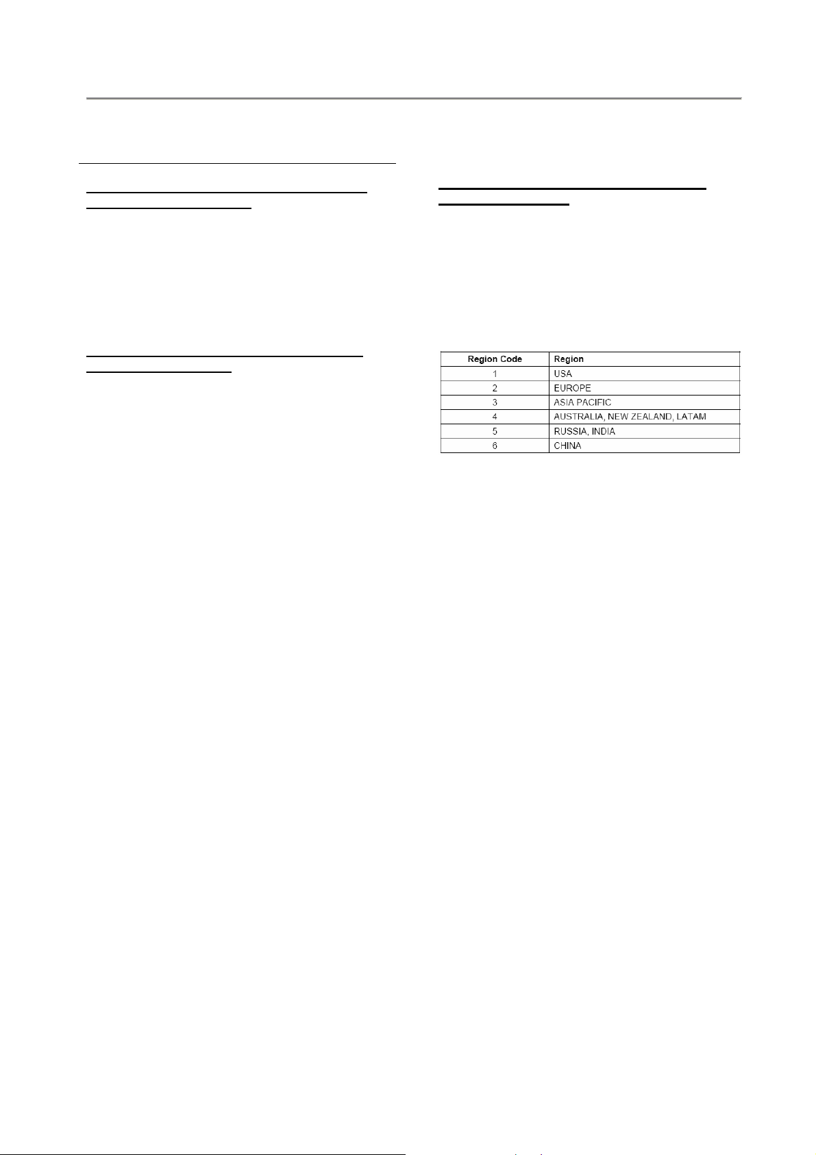
Procedure to change region code of your
portable DVD player
1. Power on player and open the DVD door
2. Press [SETUP] by remote control.
3. In Set Up Menu, select <Audio> and press [OK]
4. Press [2], [1], [2], [2], [2], [5], [<], [v]
5. Display will show the Region Code
6. Press Number Key button by remote control to
select the region code
Refer below table for your region code setting
7.
Region code “0” can be used for all regions!
8. Press
9. Power off and power on again to verify if region
Remarks:
[SETUP] to save and exit your setting
code change is done
1. Password is CONFIDENTIAL
2. Region code is printed on product type
plate. Due to DVD legislation region codes
different to assigned region may not be
released
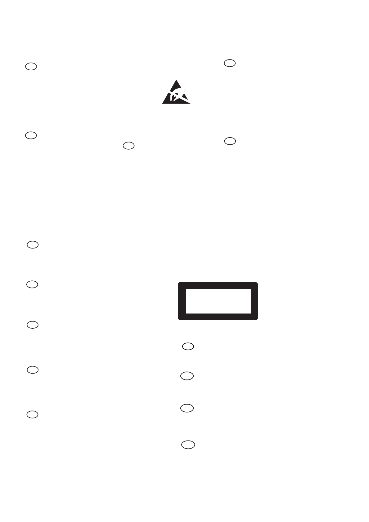
2.0 SAFTETY INSTRUCTIONS
WARNING
GB
All ICs and many other semi-conductors are
susceptible to electrostatic discharges (ESD).
Careless handling during repair can reduce life
drastically.
When repairing, make sure that you are
connected with the same potential as the mass
of the set via a wrist wrap with resistance.
Keep components and tools also at this
potential.
F
ATTENTION
Tous les IC et beaucoup d’autres
semi-conducteurs sont sensibles aux
décharges statiques (ESD).
Leur longévité pourrait être considérablement
écourtée par le fait qu’aucune précaution n’est
prise à leur manipulation.
Lors de réparations, s’assurer de bien être relié
au même potentiel que la masse de l’appareil et
enfiler le bracelet serti d’une résistance de
sécurité.
Veiller à ce que les composants ainsi que les
outils que l’on utilise soient également à ce
potentiel.
Alle ICs und viele andere Halbleiter sind
empfindlich gegenüber elektrostatischen
Entladungen (ESD).
Unsorgfältige Behandlung im Reparaturfall kan
die Lebensdauer drastisch reduzieren.
Veranlassen Sie, dass Sie im Reparaturfall über
ein Pulsarmband mit Widerstand verbunden
sind mit dem gleichen Potential wie die Masse
des Gerätes.
Bauteile und Hilfsmittel auch auf dieses gleiche
Potential halten.
D
WARNUNG
ESD
WAARSCHUWING
NL
Alle IC’s en vele andere halfgeleiders zijn
gevoelig voor electrostatische ontladingen
(ESD).
Onzorgvuldig behandelen tijdens reparatie kan
de levensduur drastisch doen verminderen.
Zorg ervoor dat u tijdens reparatie via een
polsband met weerstand verbonden bent met
hetzelfde potentiaal als de massa van het
apparaat.
Houd componenten en hulpmiddelen ook op
ditzelfde potentiaal.
I
AVVERTIMENTO
Tutti IC e parecchi semi-conduttori sono
sensibili alle scariche statiche (ESD).
La loro longevità potrebbe essere fortemente
ridatta in caso di non osservazione della più
grande cauzione alla loro manipolazione.
Durante le riparazioni occorre quindi essere
collegato allo stesso potenziale che quello della
massa dell’apparecchio tramite un braccialetto
a resistenza.
Assicurarsi che i componenti e anche gli utensili
con quali si lavora siano anche a questo
potenziale.
GB
Safety regulations require that the set be restored to its original
condition and that parts which are identical with those specified,
be used.
NL
Veiligheidsbepalingen vereisen, dat het apparaat bij reparatie in
zijn oorspronkelijke toestand wordt teruggebracht en dat onderdelen,
identiek aan de gespecificeerde, worden toegepast.
F
Les normes de sécurité exigent que l’appareil soit remis à l’état
d’origine et que soient utiliséés les piéces de rechange identiques
à celles spécifiées.
D
Bei jeder Reparatur sind die geltenden Sicherheitsvorschriften zu
beachten. Der Original zustand des Geräts darf nicht verändert werden;
für Reparaturen sind Original-Ersatzteile zu verwenden.
I
Le norme di sicurezza esigono che l’apparecchio venga rimesso
nelle condizioni originali e che siano utilizzati i pezzi di ricambio
identici a quelli specificati.
“Pour votre sécurité, ces documents
doivent être utilisés par des spécialistes agréés, seuls habilités à réparer
votre appareil en panne”.
CLASS 1
LASER PRODUCT
GB
Warning !
Invisible laser radiation when open.
Avoid direct exposure to beam.
S
Varning !
Osynlig laserstrålning när apparaten är öppnad och spärren
är urkopplad. Betrakta ej strålen.
Varoitus !
SF
Avatussa laitteessa ja suojalukituksen ohitettaessa olet alttiina
näkymättömälle laserisäteilylle. Älä katso säteeseen!
3122 110 03420
"After servicing and before returning set to customer perform a
leakage current measurement test from all exposed metal parts to
earth ground to assure no shock hazard exist. The leakage current
must not exceed 0.5mA."
DK Advarse !
Usynlig laserstråling ved åbning når sikkerhedsafbrydere er
ude af funktion. Undgå udsaettelse for stråling.
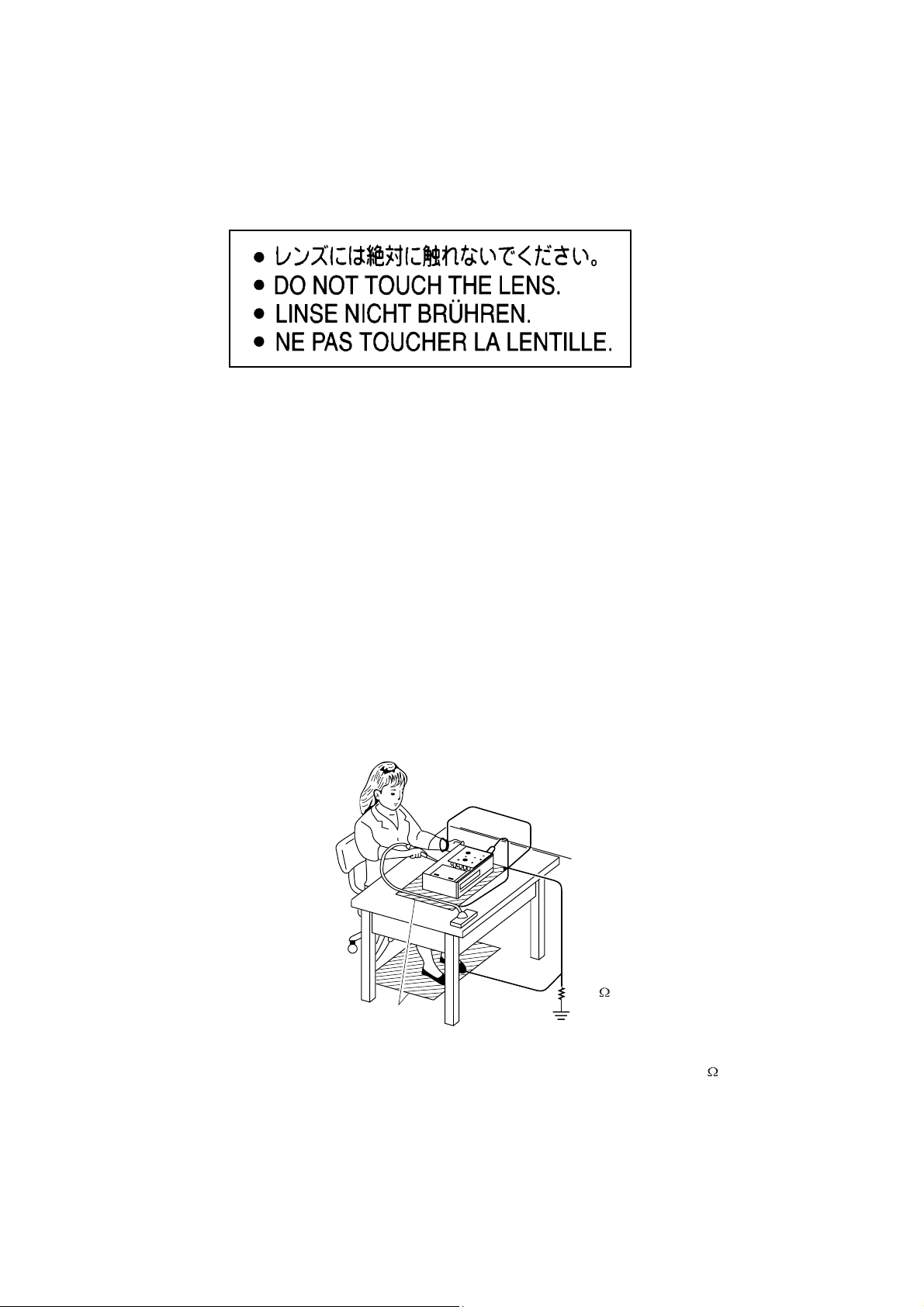
2.1 ESD PROTECTION
Whenthepowersupplyisbeingturnedon,youmaynotremovethislasercautionslabel.Ifitremoves,radiationoflaser
maybereceived.
PREPARATIONOFSERVICING
PickupHeadconsistsofalaserdiodethatisverysusceptibletoexternalstaticelectrocity.
Althoughitoperatesproperlyafterreplacement,ifitwassubjecttoelectrostaticdischargeduringreplacement,
itslifemightbeshortened.Whenreplacing,useaconductivemat,solderingironwithgroundwire,etc.to
protectthelaserdiodeformdamagebystaticelectricity.
Andalso,theLSIandICaresameasabove.
Groundconductive
wriststrapforbody.
Solderingiron
withgroundwire
orceramictype
1M
Conductivemat
Thegroundresistance
betweenthegroundline
andthegroundislessthan10
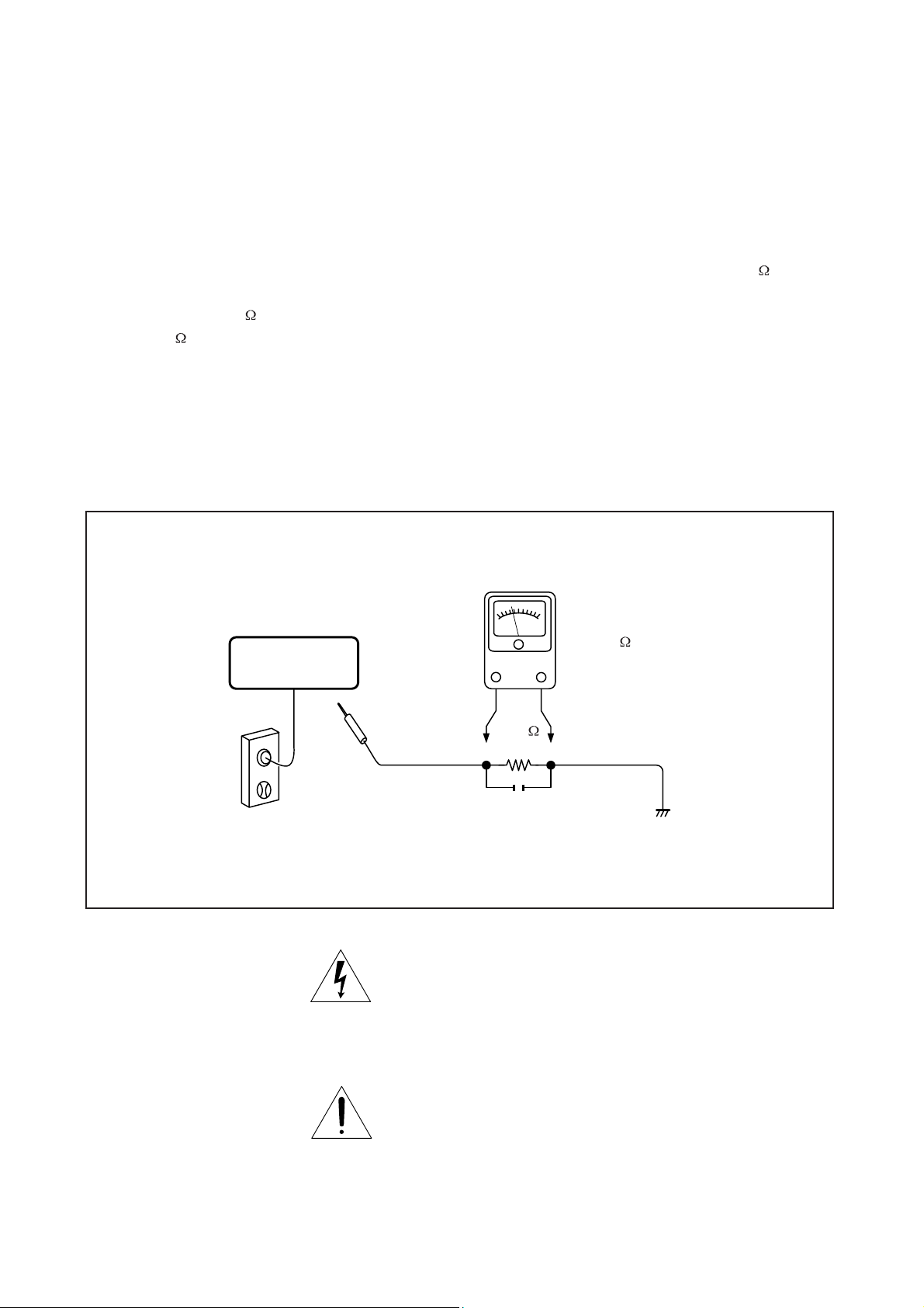
SAFTY NOTICE
LEAKAGE CURRENT CHECK
SAFTY PRECAUTIONS
Plug the AC line cord directly into a 120V AC outlet (do
not use an isolation transformer for this check). Use an
AC voltmeter, having 5000 per volt or more sensitivity.
Connect a 1500 10W resistor,paralleled by a 0.15uF
150V AC capacitor between a knomn good earth ground
(water pipe, conduit, etc.) and all exposed metal parts of
cabinet (antennas, handle bracket, metal cabinet
screwheads, metal overlays, control shafts, etc.).
READING SHOULD NOT EXCEED 0.3V
DVD VIDEO PLAYER
Measure the AC voltage across the 1500 resistor.
The test must be conducted with the AC switch on and
then repeated with the AC switch off. The AC voltage
indicated by the meter may not exceed 0.3V.A reading
exceeding 0.3V indicates that a dangerous potential
exists, the fault must be located and corrected.
Repeat the above test with the DVD VIDEO PLAYER
power plug reversed.
NEVER RETURN A DVD VIDEO PLAYER TO THE
CUSTOMER WITHOUT TAKING NECESSARY
CORRECTIVE ACTION.
AC VOLTMETER
(5000 per volt
or more sensitivity)
Good earth ground
1500
10W
such as a water pipe,
conduit, etc.
AC OUTLET
0.15uF 150V AC
Test all exposed metal.
Voltmeter Hook-up for Leakage Current Check
The lightning flash with arrowhead symbol, within an
equilateral triangle, is intended to alert the user to the
presence of uninsulated "dangerous voltage" within the
product's enclosure that may be of sufficient magnitude to
constitute a risk of electric shock to persons.
The exclamation point within an equilateral triangle is
intended to alert the user to the presence of important
operating and maintenance (servicing) instructions in the
literature accompanying the appliance.
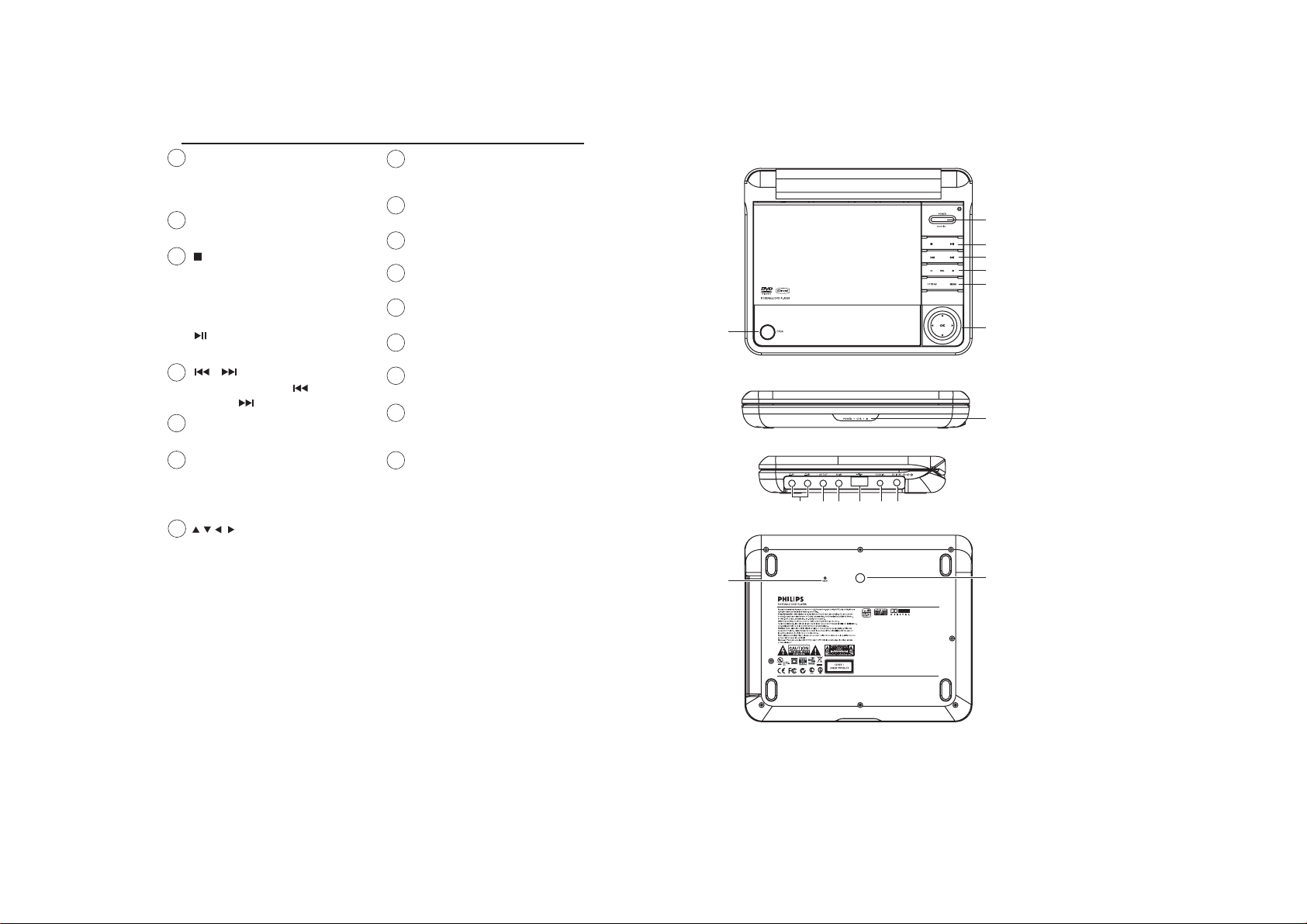
3.0 INSTRUCTIONS FOR USE
OPEN
1
Opens disc door to insert or
remove disc
Confirms selection
2
POWER
Switches the player on / off
3
Press once to stop playback
and store the stop position.
Press twice to stop playback
completely.
Start / pause / resume playback
/
4
Search backward ( ) or search
forward ( ).
5
- VOL +
Volume control.
OPTION
6
Access additional functions.
MENU
Display MUNE page.
7
,,,
Up / down / left / right cursor
OK
Confirm seletion
POWER/IR/CHR
8
Power /remote sensor /charging
indicator.
9
PHONES 1 & 2
Headphones jack
10
A/V OUT
Audio/video output jack
A/V IN
11
Audio/video input jack
USB
12
USB connector
COAXIAL
13
Digital Audio output jack
14
DC IN 9V
Power supply socket
RESET
15
Reset the player when it is
hanged up.
16
Car mounting screw hole
DVD PLAYER LAYOUT
1
9
10 11 12 13 14
15
2
3
4
5
6
7
8
16
CAUTION
Use of controls or adjustments or performance of
procedures other than herein may result in hazardous
radiation exposure or other unsafe operation.
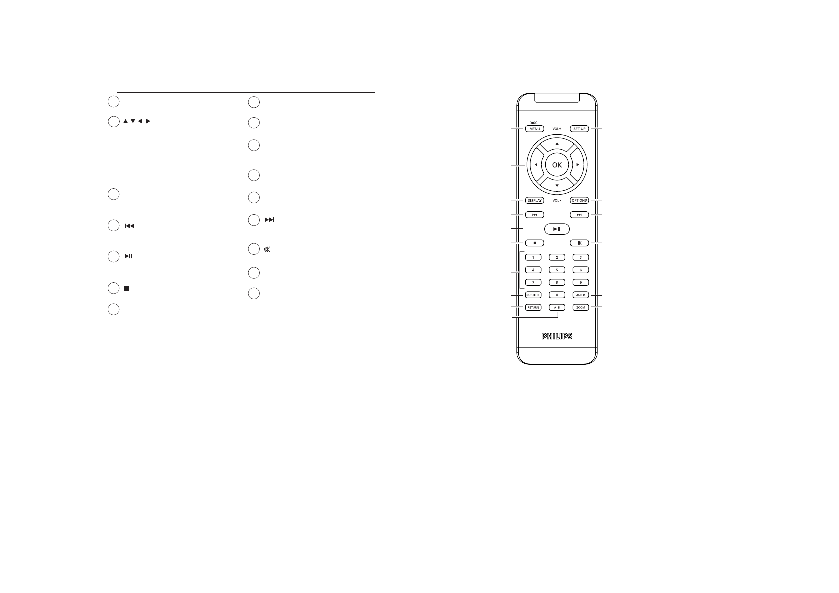
REMOTE CONTROL
MENU
1
Display MENU page.
,,,
2
Up / down / left / right
navigation key.
OK
Confirm seletion.
VOL +/-
Volume control.
DISPLAY
3
Adjust the display value of
the system.
4
Skip to previous chapter,
track or title.
5
Start / pause / resume
playback
6
Access additional functions.
7
0 - 9
Numeric keypad.
SUBTITLE
8
Subtitle language selector.
9
RETURN
For VCD menu page.
10
A - B
To repeat or loop a sequence
in a title.
11
SETUP
Enter SETUP menu.
12
OPTION
Access additional functions.
13
Skip to next chapter, track
or title.
14
Mute player volume
AUDIO
15
Audio language selector.
16
ZOOM
Enlarge video image.
10
1
2
3
4
5
6
7
8
9
11
12
13
14
15
16
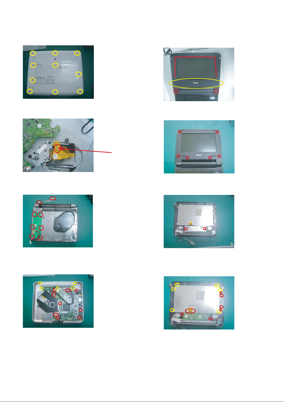
4.0 MECHNICAL INSTRUCTIONS
1. Back side of the set as shown in Fig.1
Remove the screws on the base cover.
Fig.1
2. Soldered short pattern for laser diode as shown in Fig.2
5. Remove speaker grill and screw cushion on display frame
as shown in Fig.5
Fig.5
6. Remove the screws on display frame as shown in Fig.6.
soldered
Fig.2
3.
Disconnect the flex from TFT LCD.
Remove the screws on button PCB board as shown in Fig.3
Fig.3
Disconnect the flex from DVD loader & PCB boards.
4.
Then it will able to remove DVD loader and main PCB
and Lithium battery as shown in Fig.4
Fig.6
7.
Remove the screws on IF board as shown in Fig.7.
Fig.7
8. Disconnect the flex between IF board, power board and TFT LCD.
Remove the screws on IF board, power board and TFT LCD.
As shown in Fig.8.
Fig.4
Fig.8
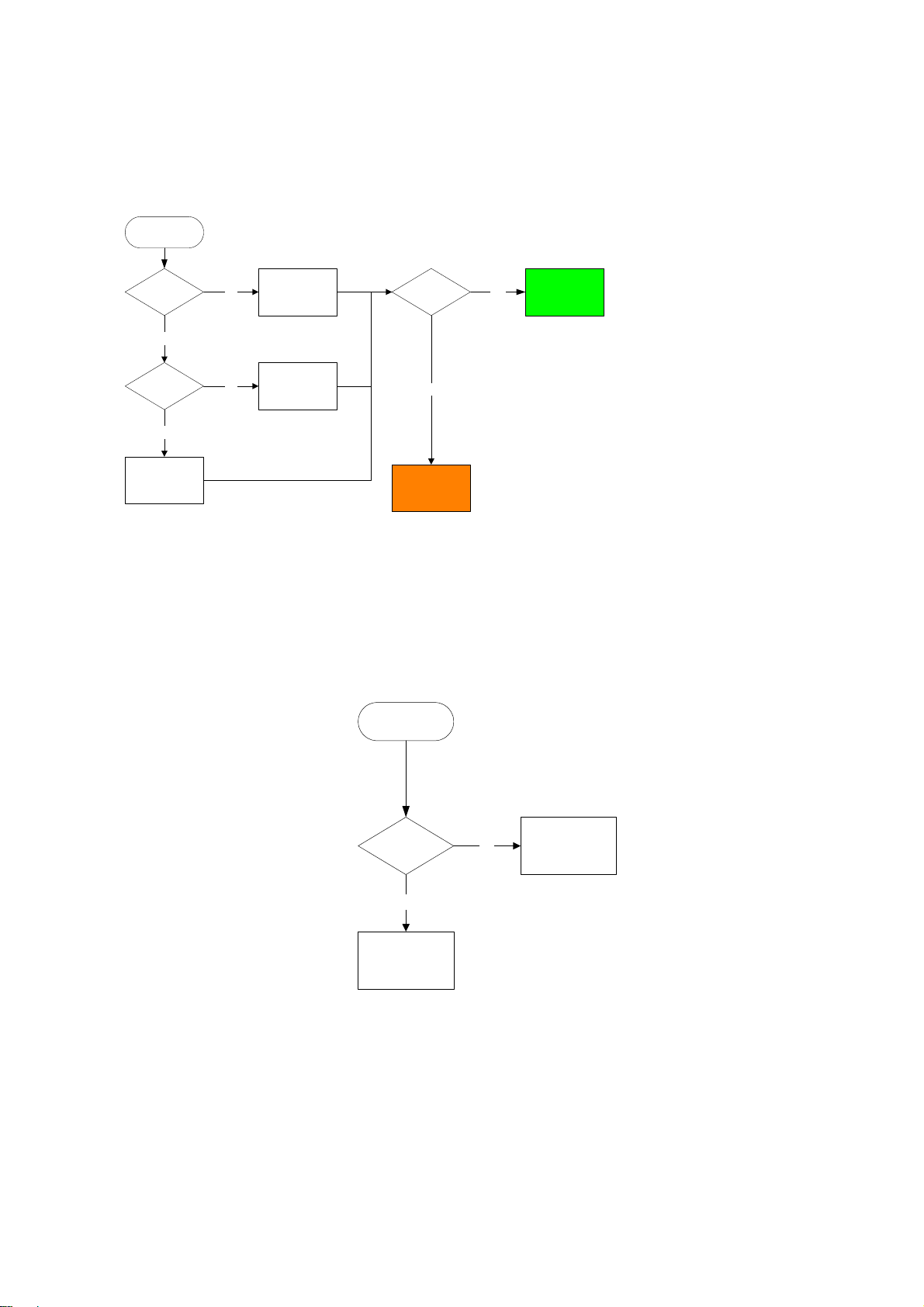
5.0 TROUBLESHOOTING
SYMPTOM: NO POWER, NO GREEN LED
start
Check if the
power cable
and
AC adapter
OK?
yes
replace cable/
no
adapter
set OK?
No defect, return
yes
set to customer
Check if the
power and play
button OK?
yes
replace MAIN
BOARD
no
replace connector
and switch unit
no
go to other
SYMPTOM
SYMPTOM: NO IMAGE OR SOUND COMES OUT FROM THE EXTERNAL OUTPUT
start
Check
operation of
the DVD drive.
Does the DVD
drive work?
no
replace DVD drive
yes
Replace the main
board or the
connector

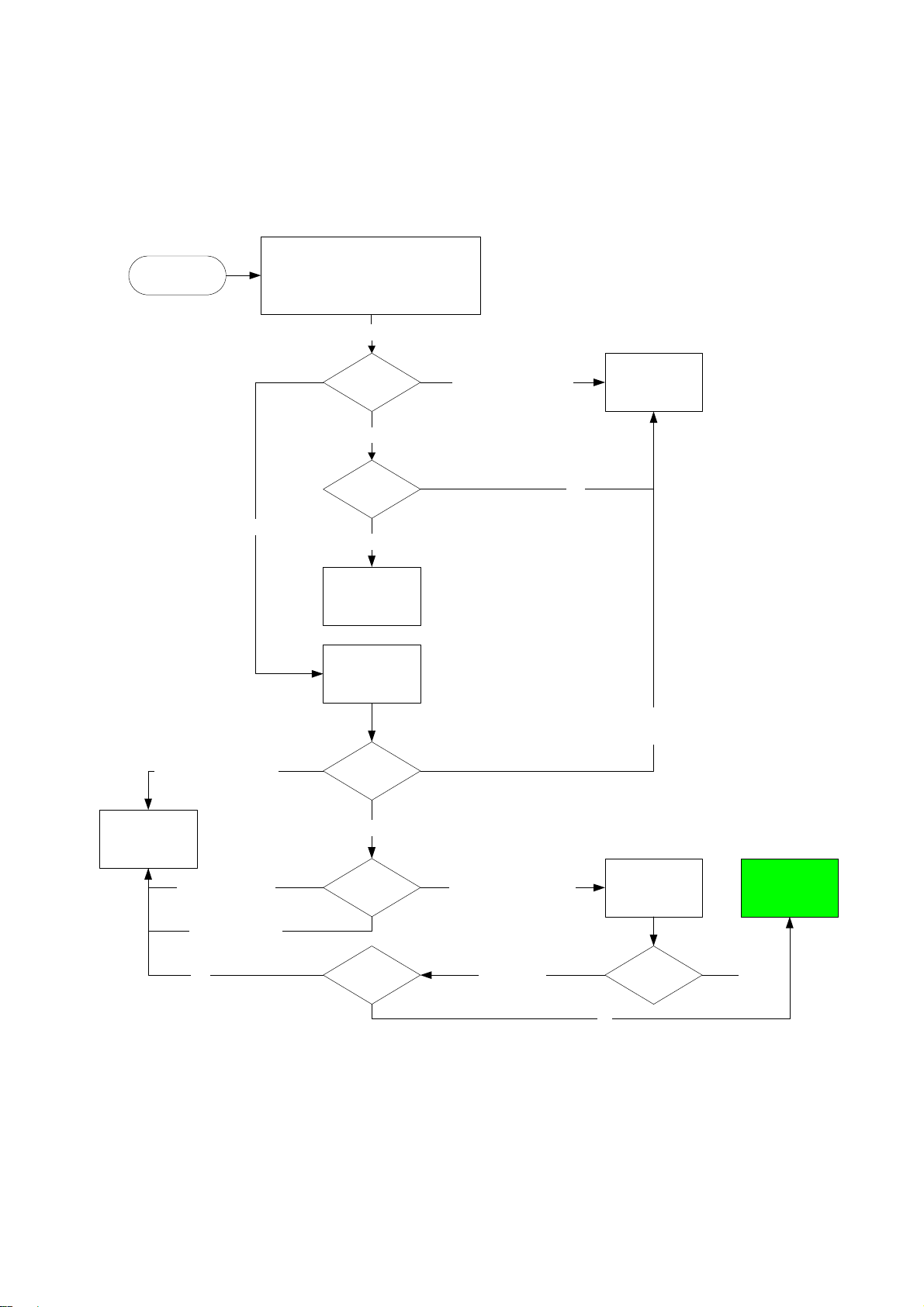
5.0 TROUBLESHOOTING
SYMPTOM: THE INITIAL SCREEN IS NOT DISPLAYED ON THE LCD
Refer to the
start
symptom NO
POWER, NO
GREEN LED
Check if the
LED on the
front lights up?
yes
Check if the
backlight is
OK?
yes
Check if the
lighting of the
LCD is OK?
yes
Replace LCD unit
or main board
no
no
no
Open the top and
bottom assembly
to check the
connector harness
Open the top and
bottom assembly
to check the
connector to the
main board
Replace broken
harness
yes
Is the
connector
harness
broken?
Is the
connector
broken?
yes
Replace LCD
harness or main
board
Connect the LCD
harness to the
LCD unit
Remove the LCD
cover and plate of
the LCD unit to
no
connector of the
check the
FL harness
no
no
Repair connector
no
Is the
connector OK?
yes
Replace FL
inverter or LCD
Remove the LCD
cover and plate of
the LCD unit to
check the
connection of the
harness to the
LCD unit
Is the
connection
OK?
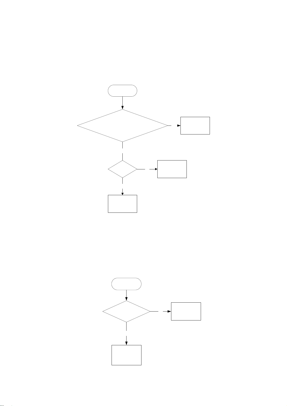
SYMPTOM: NO IMAGE OR SOUND COMES OUT FROM THE EXTERNAL INPUT
start
Replace the main
board or the
connector
yes
Replace LCD unit
or main board
5.0 TROUBLESHOOTING
SYMPTOM: THE DVD DRIVE DOES NOT WORK
Press the DISC cover switch at the center
of the DVD player and turn on the power.
Then check whether or not the optical pick-
start
up lens of the DVD drive lights. CAUTION:
Visible laser radiation when open and
interlock defeated. Do not stare into Laser
beam.
yes
Pick up lens light up OK
DVD drive does not work
Check the
optical pick up
lens?
Pick up lens does not light up at all
Check the
connectors of
the DVD drive
and main
board?
Not OK
Secure the
connection of the
DVD drive and
main board
Insert a DVD disc
and turn on the
power
What is the
reaction of the
DVD drive?
Pick up lens light up dim
OK
The DVD drive works but the initializing operation of the optical pick-up lens
does not start (the optical pick-up lens operates twice), or abnormal noise
sound
Replace DVD
drive
Replace DVD
drive or main
board
The operation of the DVD player stops at initializing display.
Is there any
oading?displayed
Nothing on display
yes
message
shown on
display
Does the
image output
stop during the
operation?
Check the DVD
HECK DISK?displayed
DVD disc OK DVD disc dirty
disc for
fingerprints, dirt,
Is the DVD
disc OK?
no
No defect, return
set to customer
5.0 TROUBLESHOOTING
SYMPTOM: THE DVD DRIVE DOES NOT OPERATE WITH BATTERY
start
Install a good battery does the LED lights up
orange while the AC adapter is connected and
does the DVD drive operate OK?
NOTE:
- For this check, use a battery which is not fully
charged (because the LED does not light when the
battery is fully charged.)
- Before this check, make sure other function work
correctly.
no
Replace batteryyes
Is the
connection of
the battery OK
inside the DVD
player?
yes
Replace main
board
no
Secure the
connection of the
battery harness
inside the DVD
SYMPTOM: NO SOUND COMES FROM THE HEADPHONES
start
player
Insert a good
headphones and check if
the problem persist?
yes
Replace main
board
no
Customer
headphones
defective

6.0 OVERALL BLOCK DIAGRAM (for PET730/732)
DV23FB
PU mechanism
DRIVER
(SA5954)
110~240V
50/60Hz
AC
Adapter
TC7W53
FlashROM
KH29LU60CBTC-70G
64M SDRAM
HY57V641620ETP-H
RF AMP & SERVO & DVD PROCESSOR
MPEG-2 DECODER & VIDEO ENCODER
MT1389DE/H-L
+5V
+5V
DRIVER +5V
+3.3V
+1.8V
74HCU04
+3.3V +5V +16V -13V
L
R
AUDIO +5V
27MHz
TFT POWER
27MHz
MX88V462UCG
AUDIO D/A
(AK4388)
TFT MONITOR
VIDEO IN
VIDEO OUT
L
AUDIO AMP
(AZ4558)
R
COAXIAL OUT
AUDIO OUT
DC IN +9V
DC / DC
(BQ24103)
(TPC8212)
(S-8232)
AUDIO +/-5V
BATTERY
TC74HC4052AFT
HWD4863
AUDIO IN
PHONE OUT
SPEAKER LOUT
SPEAKER ROUT
 Loading...