

Philips PET727 Service manual
DVD Player
Service
PET727/94/58
Service Manual
©Copyright 2008 Philips Consumer Electronics B.V. Eindhoven, The Netherlands
All rights reserved. No part of this publication may be reproduced, stored in aretrieval system or
transmitted, in any form or by any means, electronic, mechanical, photocopying, or otherwise
without the prior permission of Philips.
TABLE OF CONTENTS
. Technical Specification.........................................................1-2
. Safely Instruction..................................................................2-1
. QSG and IFU Instruction......................................................3-1
. Mechanical and Dismantling Instruction...............................4-1
. Trouble Shooting..................................................................5-1
. SW check & upgrade, Region code change.........................6-1
. Block diagram / Wiring diagram............................................7-1
. Electrical diagram.................................................................8-1
. PCBA Print-layout.................................................................9-1
. Exploded view diagram and partlist....................................10-1
. Revision list....................................................... .................11-1
Page
CLASS 1
LASER PRODUCT
Published by FK-0938 BU AVM Printed in The Netherlands Subject to modification
Version 1.1
GB
3141 785 33891
PHILIPS
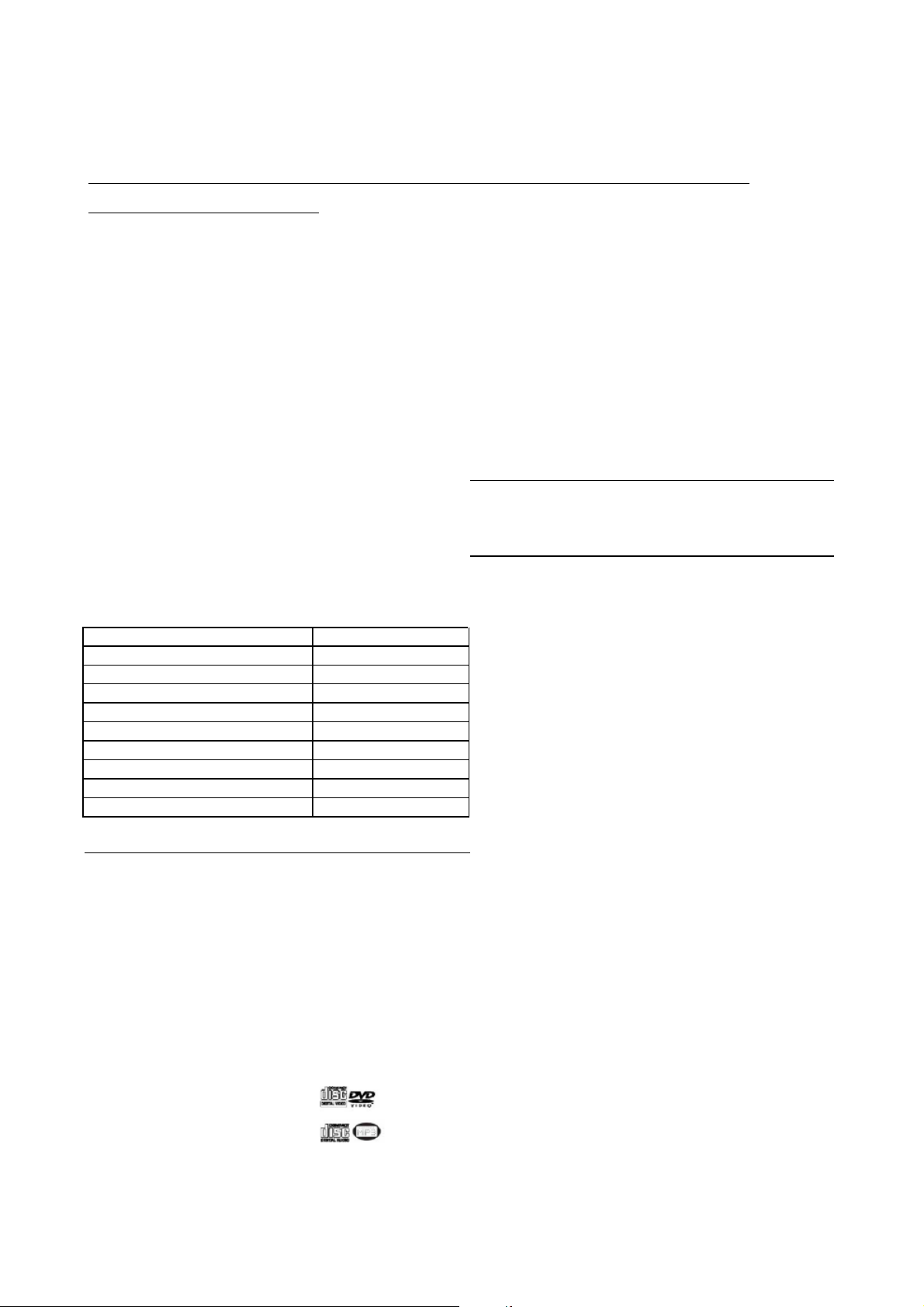
PET727/94 TECHNICAL SPECIFICATION
+HDGSKRQHRXWKHDGSKRQHRXWSXWORDG[RKP
1-2
General
Dimensions (W x H x D): 199 x158.5 x40 mm
Bear Unit Weight 0.79kg +/-5%
Supply voltage AC100-240V+/-10%
(AC adapter 90-264)
Supply Power
Consumption <15W Video Playback Format: DVD / VCD / SVCD / CD /
(AC adaptor 100/240VAC)
DC Power supply DC 7-15.7V
Standby Power <0.5W
(AC adapter, no load) 164VAC
Audio System Disc Diamete 8cm/12cm
Output voltage 1KHZ 2+/-0.2V
THD 20-20KHZ(%) </=0.1%
Dynamic range 1KHZ >/=80dB
Signal/Noise ratio >/=85dB
Frequency response +/-3dB
(20Hz-20Khz)
Channel Separation 1KHZ >/=80dB
Channel Balance 1KHZ </=1.5dB
Current consumption
Playback time ı3hrs
Batter\ Capacity – ı1700mAH
Lithium-ion 7.4V
Discharge cut-off 5.8-6V
voltage(3.0 V for single cell)
Battery discharge cut </=50uA
off current
Battery Charge </=8.4V
voltage(1.2V for single cell)
Charging time <4hrs
Playback disc type:
Pixel specification
Max.1 bright-dot & max. 3 dark-dots
Factory Service Mode (FSM)
DVD video, DVD+/-R,
DVD+/-RW, CD, CD-R, CDRW, CD-ROM, VCD, SVCD,CD, CD-R, CD-RW,
MP3-CD,dvix
JPEG
0D[LPXPRXWSXWSRZHU P:
)UHTXHQF\UHVSRQVH G%
615$ZJKW ! G%+]N+=
7+'.K]
'\QDPLFUDQJH.K] ! G%
/HIH5LJKW&KDQQHO !G%
6HSDUDWLRQ ! G%
/HIW5LJKW&KDQQHO G%
%DQODQFH
6XSSRUWHGGLVFW\SH
9LGHR3OD\EDFN
)RUQDWV
$XGLR3OD\EDFN
)RUPDWV
2.0 SAFTETY INSTRUCTIONS
WARNING
GB
All ICs and many other semi-conductors are
susceptible to electrostatic discharges (ESD).
Careless handling during repair can reduce life
drastically.
When repairing, make sure that you are
connected with the same potential as the mass
of the set via a wrist wrap with resistance.
Keep components and tools also at this
potential.
F
ATTENTION
Tous les IC et beaucoup d’autres
semi-conducteurs sont sensibles aux
décharges statiques (ESD).
Leur longévité pourrait être considérablement
écourtée par le fait qu’aucune précaution n’est
prise à leur manipulation.
Lors de réparations, s’assurer de bien être relié
au même potentiel que la masse de l’appareil et
enfiler le bracelet serti d’une résistance de
sécurité.
Veiller à ce que les composants ainsi que les
outils que l’on utilise soient également à ce
potentiel.
2-1
ESD
D
WARNUNG
Alle ICs und viele andere Halbleiter sind
empfindlich gegenüber elektrostatischen
Entladungen (ESD).
Unsorgfältige Behandlung im Reparaturfall kan
die Lebensdauer drastisch reduzieren.
Veranlassen Sie, dass Sie im Reparaturfall über
ein Pulsarmband mit Widerstand verbunden
sind mit dem gleichen Potential wie die Masse
des Gerätes.
Bauteile und Hilfsmittel auch auf dieses gleiche
Potential halten.
NL
WAARSCHUWING
Alle IC’s en vele andere halfgeleiders zijn
gevoelig voor electrostatische ontladingen
(ESD).
Onzorgvuldig behandelen tijdens reparatie kan
de levensduur drastisch doen verminderen.
Zorg ervoor dat u tijdens reparatie via een
polsband met weerstand verbonden bent met
hetzelfde potentiaal als de massa van het
apparaat.
Houd componenten en hulpmiddelen ook op
ditzelfde potentiaal.
I
AVVERTIMENTO
Tutti IC e parecchi semi-conduttori sono
sensibili alle scariche statiche (ESD).
La loro longevità potrebbe essere fortemente
ridatta in caso di non osservazione della più
grande cauzione alla loro manipolazione.
Durante le riparazioni occorre quindi essere
collegato allo stesso potenziale che quello della
massa dell’apparecchio tramite un braccialetto
a resistenza.
Assicurarsi che i componenti e anche gli utensili
con quali si lavora siano anche a questo
potenziale.
GB
Safety regulations require that the set be restored to its original
condition and that parts which are identical with those specified,
be used.
NL
Veiligheidsbepalingen vereisen, dat het apparaat bij reparatie in
zijn oorspronkelijke toestand wordt teruggebracht en dat onderdelen,
identiek aan de gespecificeerde, worden toegepast.
F
Les normes de sécurité exigent que l’appareil soit remis à l’état
d’origine et que soient utiliséés les piéces de rechange identiques
à celles spécifiées.
D
Bei jeder Reparatur sind die geltenden Sicherheitsvorschriften zu
beachten. Der Original zustand des Geräts darf nicht verändert werden;
für Reparaturen sind Original-Ersatzteile zu verwenden.
I
Le norme di sicurezza esigono che l’apparecchio venga rimesso
nelle condizioni originali e che siano utilizzati i pezzi di ricambio
identici a quelli specificati.
“Pour votre sécurité, ces documents
doivent être utilisés par des spécialistes agréés, seuls habilités à réparer
votre appareil en panne”.
CLASS 1
LASER PRODUCT
GB
Warning !
Invisible laser radiation when open.
Avoid direct exposure to beam.
S
Varning !
Osynlig laserstrålning när apparaten är öppnad och spärren
är urkopplad. Betrakta ej strålen.
Varoitus !
SF
Avatussa laitteessa ja suojalukituksen ohitettaessa olet alttiina
näkymättömälle laserisäteilylle. Älä katso säteeseen!
3122 110 03420
"After servicing and before returning set to customer perform a
leakage current measurement test from all exposed metal parts to
earth ground to assure no shock hazard exist. The leakage current
must not exceed 0.5mA."
Advarse !
DK
Usynlig laserstråling ved åbning når sikkerhedsafbrydere er
ude af funktion. Undgå udsaettelse for stråling.
2-2
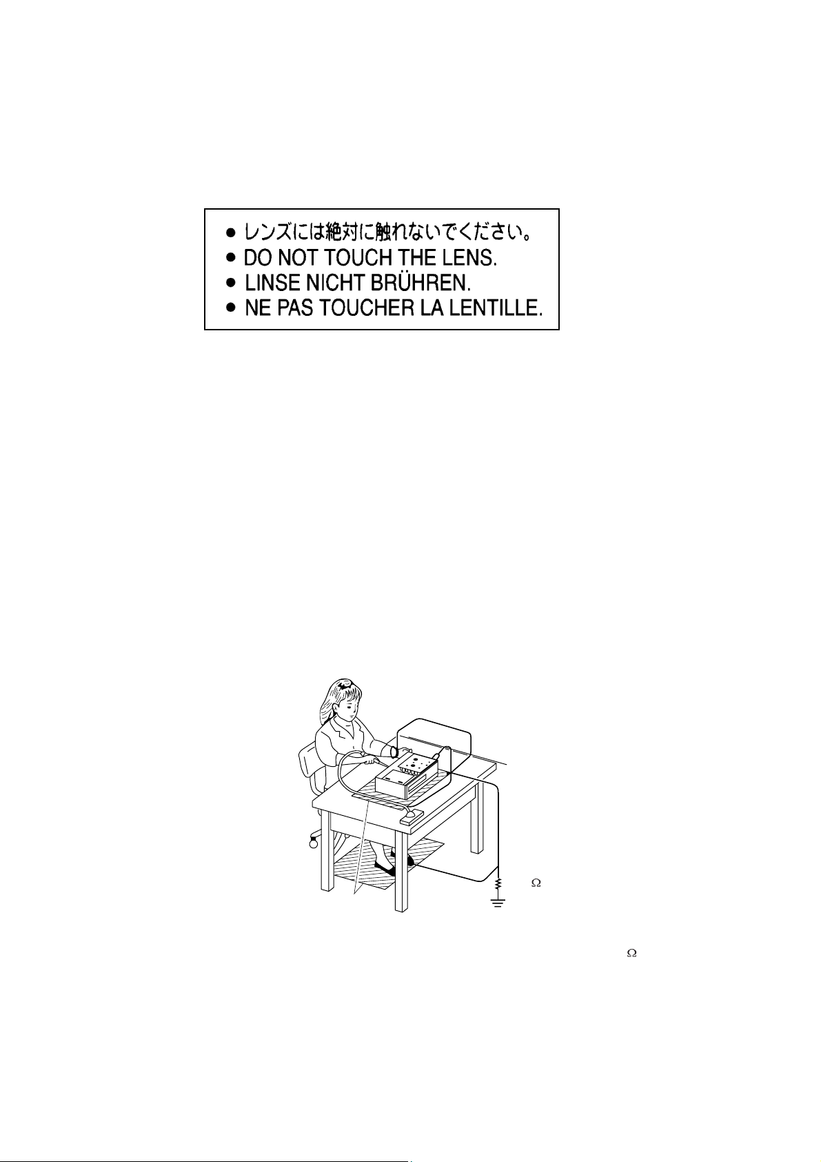
2.1 ESD PROTECTION
Whenthepowersupplyisbeingturnedon,youmaynotremovethislasercautionslabel.Ifitremoves,radiationoflaser
maybereceived.
PREPARATIONOFSERVICING
PickupHeadconsistsofalaserdiodethatisverysusceptibletoexternalstaticelectrocity.
Althoughitoperatesproperlyafterreplacement,ifitwassubjecttoelectrostaticdischargeduringreplacement,
itslifemightbeshortened.Whenreplacing,useaconductivemat,solderingironwithgroundwire,etc.to
protectthelaserdiodeform
Andalso,theLSIandICaresameasabove.
Solderingiron
withgroundwire
orceramictype
damagebystaticelectricity.
Groundconductive
wriststrapforbody.
1M
Conductivemat
Thegroundresistance
betweenthegroundline
andthegroundislessthan10
SAFTY NOTICE
LEAKAGE CURRENT CHECK
2-3
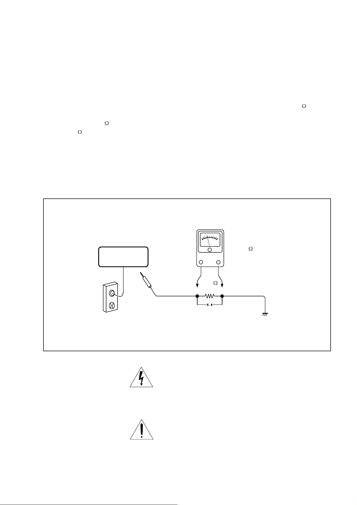
SAFTY PRECAUTIONS
Plug the AC line cord directly into a 120V AC outlet (do
not use an isolation transformer for this check). Use an
AC voltmeter, having 5000 per volt or more sensitivity.
Connect a 1500 10W resistor,paralleled by a 0.15uF
150V AC capacitor between a knomn good earth ground
(water pipe, conduit, etc.) and all exposed metal parts of
cabinet (antennas, handle bracket, metal cabinet
screwheads, metal overlays, control shafts, etc.).
READING SHOULD NOT EXCEED 0.3V
DVD VIDEO PLAYER
Measure the AC voltage across the 1500 resistor.
The test must be conducted with the AC switch on and
then repeated with the AC switch off. The AC voltage
indicated by the meter may not exceed 0.3V.A reading
exceeding 0.3V indicates that a dangerous potential
exists, the fault must be located and corrected.
Repeat the above test with the DVD VIDEO PLAYER
power plug reversed.
NEVER RETURN A DVD VIDEO PLAYER TO THE
CUSTOMER WITHOUT TAKING NECESSARY
CORRECTIVE ACTION.
AC VOLTMETER
(5000 per volt
or more sensitivity)
Good earth ground
1500
10W
such as a water pipe,
conduit, etc.
AC OUTLET
0.15uF 150V AC
Test all exposed metal.
Voltmeter Hook-up for Leakage Current Check
The lightning flash with arrowhead symbol, within an
equilateral triangle, is intended to alert the user to the
presence of uninsulated "dangerous voltage" within the
product's enclosure that may be of sufficient magnitude to
constitute a risk of electric shock to persons.
The exclamation point within an equilateral triangle is
intended to alert the user to the presence of important
operating and maintenance (servicing) instructions in the
literature accompanying the appliance.
2.2 SAFETY INSTRUCTIONS
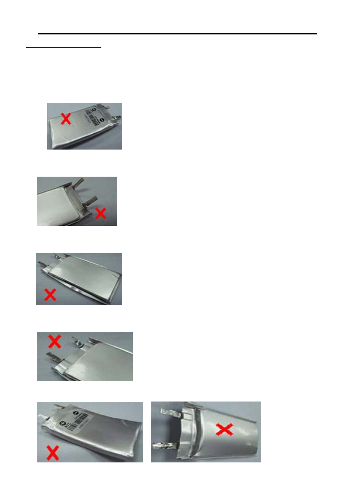
Battery Handling Guideline
Since the battery is packed in soft package, to ensure its better performance, it’s very important to carefully handle
the battery
2.2.1 Soft Aluminium foil
The soft aluminum packing foil is very easily damaged by sharp edge parts such as Ni-tabs, pins and needles.
x Don’t strike battery with any sharp edge parts
x Trim your nail or wear glove before taking battery
x Clean worktable to make sure no any sharp particle
2.2.2 Sealed edge
Sealing edge is very flimsy
x Don’t bend or fold sealing edge
2-4
2.2.3 Folding edge
The folding edge is form in battery process and passed all hermetic test.
x Don’t open or deform folding edge
2.2.4 Tabs
The battery tabs are not so stubborn especially for aluminum tab.
x Don’t bend tab
2.2.5 Mechanical shock
x Don’t Fall, hit, bend battery body
2.2.6 Short
Short terminals of battery is strictly prohibited, it may damage battery.
3-1
The following excerpt of the Quick Start Guide serves as an introduction to the set.
The complete Direction For Use can be download in different languages from
Philips Customer Contact & Support site: www.p4c.philips.com
Philips Portable DVD Player PET727
Quick Start Guide
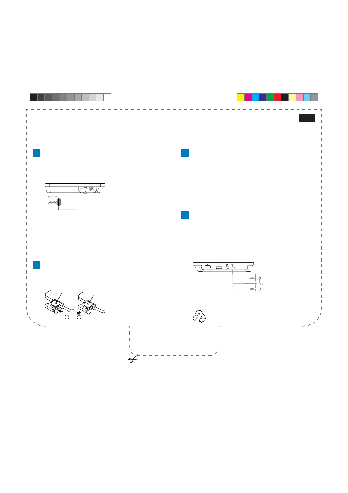
1
Charge the built-in battery
Step 1 Switch the ON/OFF slide selector to the OFF position.
Step 2 Connect the supplied AC adaptor to the DC IN 12V socket on
the DVD Player and to the AC outlet.
The red charge indicator turns on. It takes about 4 hours to fully charge
the battery.
When the battery is fully charged, the red charge indicator turns off.
Tip
- You can only charge the battery when the temperature is between
0°C and 35°C.
- When headphones are connected to the DVD Player, the fully
charged battery lasts about 2.5 hours.
2
Install remote control battery
Step 1 Open the battery compar tment.
Step 2 Insert 1 CR2025 batter y with correct polarity (+/-) as indicated.
Step 3 Close the battery compar tment.
CR2025
CR2025
3
Play discs
Step 1 Lift the display panel.
Step 2 Switch the OPEN slide selector to the right to open the disc
compartment.
• (For the fi rst time) Remove the protective card.
Step 3 Insert a disc with the printed side facing up.
Step 4 Push the lid down to close the disc compartment.
Disc starts to play automatically. If not, press
If a menu appears, select an item and then press OK to start play.
4
Connect a TV
On the DVD Player,
Step 1 Connect the black end of the supplied AV cable to the AV OUT
socket.
On the TV,
Step 1 Connect the white end to the left audio input socket and the red
end to the right audio input socket.
Step 2 Connect the yellow end to the video input socket.
OK or 2; .
TV
AUDIO IN
VIDEO IN
English
1
2
3
OPEN HERE
PHILIPS
3-2
What’s in the box
Check and identify the contents of your package:
Portable DVD Player•
Remote control•
Battery for remote control•
AC power adaptor (ADS-18C-12N 12012GPG)•
AV cable •
Car pouch•
User Manual•
Quick Start Guide•
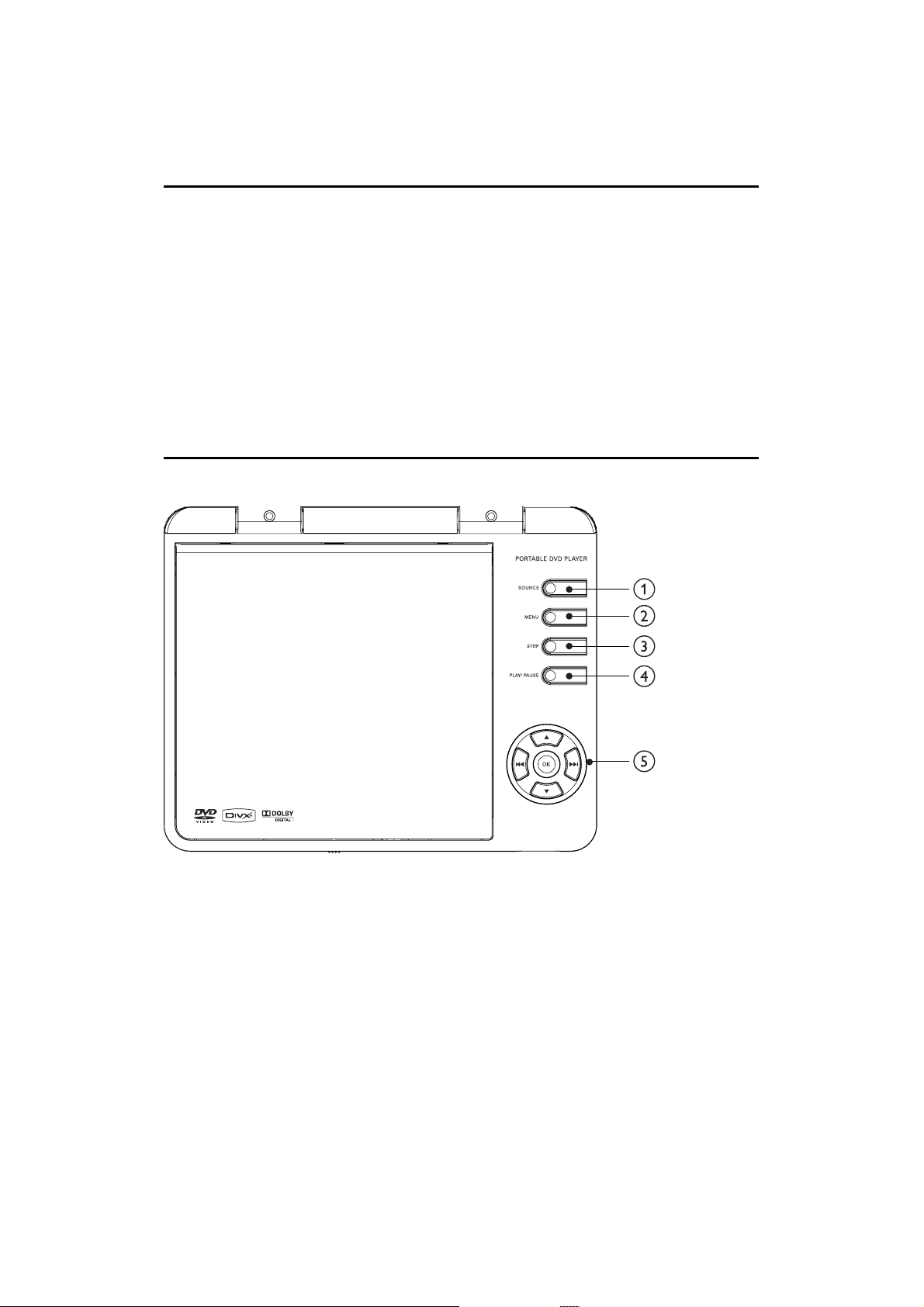
Overview of the main unit
a SOURCE
Switch between DISC and USB.•
b MENU
For DVD, access or exit the root menu•
For VCD and SVCD, turn PBC (playback control) on or off in •
PBC mode
c STOP
Stop disc play•
d PLAY/PAUSE
Start, pause or resume disc play•
e Navigation keys
/ / /
Select the up/down/left/right item•
/
Press to skip to the previous or next title/chapter/track•
Press and hold for fast-backward or fast-forward search•
OK
Confi rm an entry or selection•
3-3
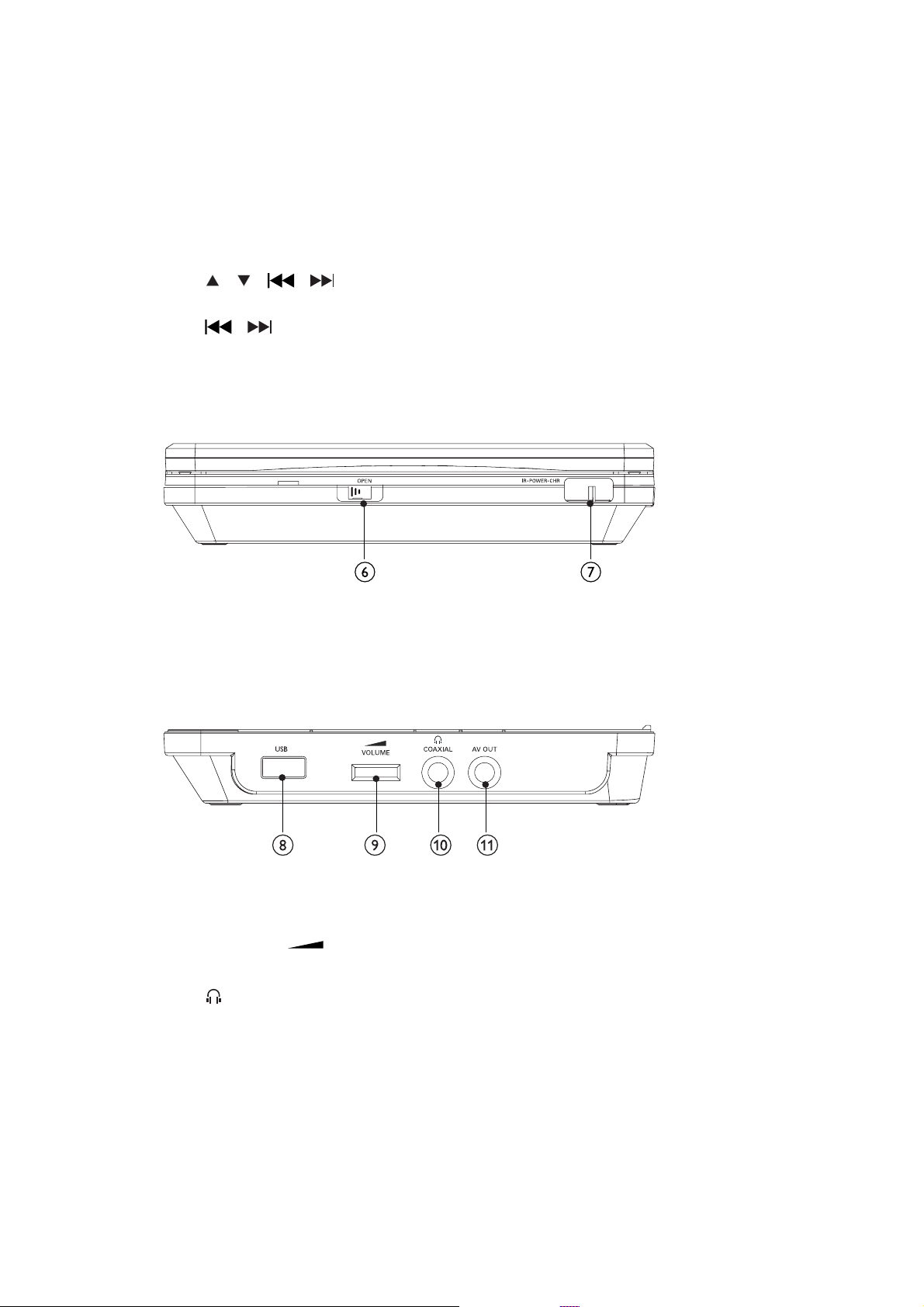
f OPEN
Open the disc compartment•
g IR/POWER/CHR
Remote sensor, power indicator, or charge indicator•
h USB
USB socket.•
i VOLUME
Adjust volume level•
j
COAXIAL
Connect headphones•
Socket for coaxial output•
k AV OUT
Socket for audio/video output•
3-4
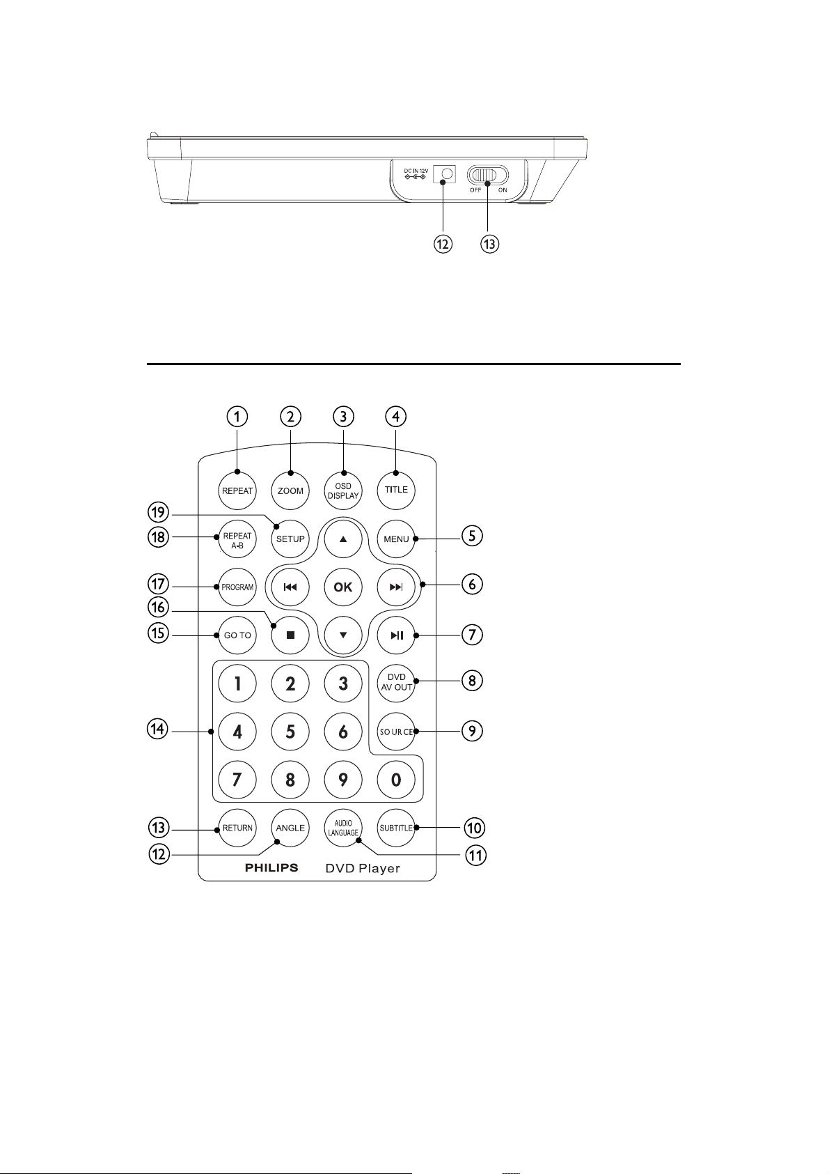
l DC IN 12V
Power supply socket•
m ON/OFF
Turns on/off DVD player.•
Overview of the remote control
a REPEAT
Select a repeat mode•
b ZOOM
Zoom into or out of an image•
c OSD DISPLAY
Display the current play status or disc information•
d TITLE
Access or exit the title menu of a disc•

e MENU
For DVD, access or exit the root menu•
For VCD and SVCD, turn PBC (playback control) on or off in •
PBC mode
3-5
f
/ / /
Select the up/down/left/right item•
/
Press to skip to the previous or next title/chapter/track•
Press and hold for fast-backward or fast-forward search•
OK
Confi rm an entry or selection•
g
Start, pause or resume disc play•
h DVD AV OUT
Switch between • [TV Mode (PAL)], [Dual Screen (NTSC)] and
[AV OUT OFF]
i SOURCE
Switch between DISC and USB.•
j SUBTITLE
Select a subtitle language•
k AUDIO LANGUAGE
Select an audio language or an audio channel•
l ANGLE
Select a viewing angle of a DVD•
m RETURN
(For VCD, PBC on) Return to the previous menu•
n Numeric Keypad 0 - 9
Select an item to play•
o GO TO
Skip to a chapter/track/title or a play time•
p
Stop disc play•
q PROGRAM
Access or exit the program menu•
r REPEAT A-B
Mark the section for repeat play•
s SETUP
Access or exit the setup menu•

4-1
Mechanical and Dismantling Instructions
Dismantling Instruction
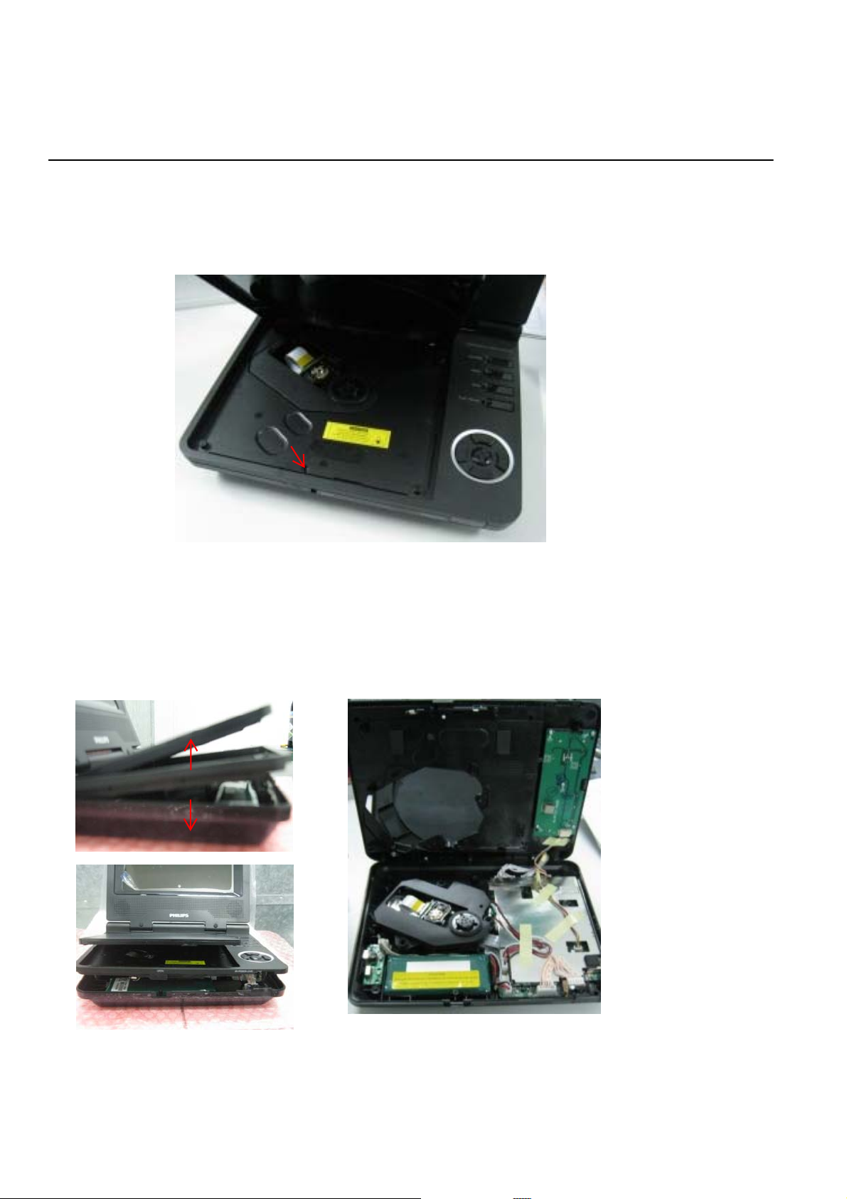
The following guidelines show how to dismantle the player. (The DVD Player should be power off during the dismantling )
Step1: Reverse the set, remove 4 PAD from the Bottom Plate, and remove 7 screws around the Bottom Plate (Figure 1).
You can make it through the instruction as below for taking tray (Figure 2)
Step2:
Note: Make sure to operate gently otherwise the guider would be damaged.
Figure 1
Figure 2
4-2
Mechanical and Dismantling Instructions
Dismantling Instruction
: If it is necessary to dismantle Loader or PCB Board, the Mid-CASE moudle should be removed first (Figure 3 & 4).
Step3
Need remove 1 screw as below figure:
Note: Make sure to operate gently otherwise the guider would be damaged.
Disassemble the Mid-CASE: With two hands to open & remove the Mid-CASE as below instruction (Figure 4).
Step4::
Note: Make sure to operate gently otherwise the guider would be damaged.
Figure 3
Figure 4
 Loading...