

Page 1
SWITCHED
MODE
POWER
SUPPLY
PE
OPERATING
BEDIENUNGSANLEITUNG 一 see
NOTICE
1
204/30
MANUAL
D'EMPLOI
{8415
012
04301)
—
Page
—
page
2
io
18
ae
DE
ごと
デメ
ブー
4822
872
870320
PHILIPS
*
PHILIPS
Printed
40431
-
INDUSTRIAL
in
Belgium.
&
ELECTRO-ACOUSTIC
SYSTEMS
DIVISION
-
EINDHOVEN
-
THE
NETHERLANDS
1987
Page 2

Page 3
CONTENTS - ==
LIST
OF
FIGURES
ABBREVIAT
SAFETY
EONS
PRECAUTIONS - -
SYMBOLS
IMPAIRED
IMPORTANT
WARNING
WARNING
WARNING
SAFETY
WARNINGS
A
B
C
UNPACKING
WARNING
D
GENERAL
1.
INTRODUCTION
CHARACTERISTICS
ELECTRICAL
pri
a
+
GENERAL
.
de
«OUTPUT
e
+
fd
it
«2.
det
fed
TO
mi
PI
Co
UI
mi
Co
ds
>
Ne
Ls
1.
INPUT
OUTPUT
AS
AS
PROTECTION
ENVIRONMENTAL
CLIMATIC
ENVIRONMENTAL
MECHANICAL
OVERALL
MOUNTING
ACCESSORIES
OPERATING
OPTIONAL
NA
го Го
о
RA
Nİ
Rİ
Го Го Го
FO
DO
B
----------
PROTECTION
EFFECTS
VOLTAGE
CURRENT
CONDITIONS
DIMENSIONS
7-2
eee
- - - - - - - - - - - - - - -
DATA
(IEC
478-2)
STABILIZER
STABILIZER
DATA
TESTS
DATA
- - - - - - - - - - - - - - 6
AND
MASS
MANUAL
eee
2
LIST
OF
FIGURES
FIG.
3
200
224
230
267
310
320
541
700
1000
80 PE
1204/30
External
Local
sensing
Remote
Energy
Unit
Unit
sensing
reserve
Al
A2
Dielectric
Connection
Circuit
diagram
Output
connections
characteristic
...........
..........,...,....sssssssserss
.......
(TTL
說
signal)
.........
......
...,............
Strength
of
external
test
риа
set-up
mains
filter
,.,.....,.....,,...
............
..
μυ.
k
nn
..............
..........
26
26
DIRECTIONS
FOR
INSTALLATION
INITIAL
PN
45
στ
οι
σι
τα
NH
Ho
MOUNTING
DISMANTLING
SENSING
LOCAL
REMOTE
QUTPUT
OUTPUT
MAINS
PROTECTIVE
Lu LI La
Li (3
LU
I
62
02
62
62
OPERATING
GENERAL
SWITCHING
1.
.2.
Peewee
2.1.
CONTROLS,
SERIES
SERIES
PARALLEL
INFLUENCE
SS
EXTERNAL
1,
REMOTE
2,
ENERGY-RESERVE
2
APPLICATIONS
WMAP
二
RESERVE
ADJUSTMENTS
GENERAL
・
MAENS
OUTPUT
.1.
Www
OUTPUT
SERVICING
FUSE
лама
6.
6.1.
TABLE 1 RACKS
USE
- =
--
INSPECTION
INSTRUCTIONS
CONNECTIONS
SENSING
SENSING
CONNECTIONS
COMBINATIONS
CONNECTION
ACTION
INSTRUCTIONS
INFORMATION
"ON"
ADJUSTMENTS,
AND
PARALLEL
CONNECTION
CONNECTION
OF
MAINS
CONTROLS - -
ON-OFF
AND
OR
PHF
INPUT
ADJUSTMENTS
REPLACEMENT
AND
FEMALE
20
000000000
INDICATORS
CONNECTIONS
INTERRUPTION
= - - - - + - - - - -
INDICATION
ADVANTAGE
CONNECTORS
(PWF)
OF
~ - ~ - -- - -
THE
AND
POWER
6
TERMINALS
8
9
ABBREVIATIONS
ADJ
BW
fn
fm
6
lm
Io
lon
LS
M
M-S
ave
PARD
Po
p-p
ΡΗΕ
RS
r.m.s
Rp
5
T
Ta
tr
U
Um
Uomax
U
Uan
Up
Ut
Adjustment
Bandwidth
Function
Mains
External
Mains
Output
Nominal
Local
Master
Master-Siave
Overvoltage
Periodic
Output
Peak-to-peak
Power
Remote
Root
Progranming
Stave
Mounting
Ambient
Energy-reserve
Rack
Mains
Maximum
Output
Nominal
Programming
Trip
frequency
supply
current
current
output
sensing
protection
and
power
failure
sensing
mean
square
resistor
unit
temperature
unit
(height)
voltage
output
voltage
output
voltage
voltage
current
random
deviatíon
value
indication
value
(5,08
mm)
time
DIN
voltage
voltage
0.V.P.
DIN
41494
41494
*
PE
1204/30
$
87.03.19
Page 4

Page 5
SAFETY
In
the
it is
thoroughly
tempting
This
apparatus
PRECAUTIONS
interests
strongly
understood
to
put
has
recommended
this
Class 1 standards
supplied
formation
to
a
safe
Where
symbols
CAUTION
nance
truction
WARNING
quires
vent
ensure
condition.
necessary,
procedures
correct
personal
in a safe
and
warnings
safe
are
marked
is
used
of
eguipment
calls
injury.
operation
to
attention
procedures
SYMBOLS
4
High
voltage
LN
*
Any
Λ
©
interruption
outside
tive
Live
part
Read
the
see
Section
Protective
the
earth
terminal
apparatus,
dangerous ; intentional
IMPAIRED
Whenever
paired,
secured
referred
Safety
ple,
rements
protection
the
it
is
the
instrument
against
to
the
instrument
ar
shows
SAFETY
likely
any
appropriate
signs
¿IMPORTANT
Nherever
nings
subject
out
tion
WARNING
source,
to a protective
earthed
tions.
appropriate
are
continuity.
their
below
the
in
inserted
meaning,
:
A
Before
protective
accordance
of
safety
by
to
all
instrument
been
manufactured
as
listed
in
condition.
which
and
warning
on
indicate
in
the
order
or
and
apparatus.
correct
to
other
to a potential
or
1000 V (red)
(black/yellow)
operating
instructions
4.
earth
(ground)
of
the
protective
or
disconnection
is
likely
interruption
PROTECTION
that
safety-protection
must
operation.
likely
of
servicing
to
to
damage.
is
fails
WARNINGS
in
the
in
short,
However,
always
refer
any
connection
earth
conductor.
with
personnel
that
this
intended
into
Sect.
This
must
be
to
retain
caution
prevent
property.
practices
to
be
made
The
be
impaired
perform
manual,
reminder
if
there
to
terminal
The
the
[EC
and
page
is
users
service.
according
2.1.1.
manual
and
contains
followed
the
apparatus
statements
operating
damage
to or
danger
in
order
(black/yeltow),
terminal
conductor
of
make
the
is
prohibited.
(btack)
the
has
inoperative
matter should
authority.
if,
the
intended
four
important
form
to
is
the
is
power
any
detailed explana-
made
to a voltage
shal]
be
supply
348
safety
equipment,
read
before
to
safety
has
been
hy
the
and/or
or
mainte-
des-
that
to
pre-
inside
protec-
apparatus
been
and
then
for
exam-
measu-
war-
maintain
doubt
connected
must
regula-
and
at-
in-
user
in
re-
or
im-
be
be
ab-
be
When a power
environment,
condensation
tion : ensure
are
strictly
adhered
if a three-core
plug
shall
protective
not
be
protective
The
cross-section
equat
accordance
If
the
connected
The
cross-section
cient
mounted
negated
to
power
and
in
be
earth
conductor.
the
cross-section
with
to
the
depending
this
WARNING
nected
Before
thoroughly
placements,
qualified
instrument
ver
possible.
capacitors
to
the
making
person
After
understood
repairs,
completely
to
WARNING
with
fuses
For
the
shall
and
The
supply
the
tuses
fied
type
paired
prohibited.
all
voltage sources
the
pawer
faults, a blown
replacing
UNPACKING
On
delivery,
to
ascertain whether
sit.
Retain
wer
*
Carry
minal
res.
damage.
cordance
*
In
safety
led
Service
to
all
supply
Visual
inspection
aut a mechanical
blocks,
Check
Check
with
Claims
the
event
of
the
with
the
Organisation
facilitate
packing
have been
items
WARNING
type-plate
must
supply
therefore
input
inserted
contact.
by
the
of
the
supply
Safety
of
on
rack.
B
delivery,
power
source
any
connection,
aware
After
discharge
C
continued
required
be
used
the
instrument
is
electronically
fuse
fuse,
always
check
materials
external
for
that
the
accessories
of
obviaus
supply
carrier
the
repair
D
If
nominal
be
suitably
is
braught
that
to.
cable
into a socket
use
the
earth
local
safety
is
rack-mounted,
Earth
the
earth
the
and
observed.
etc...
af
the
disconnected
disconnection,
before
rated
for
short-circuiting
when a fuse
indicates a major
the
power
any
danage
accaunted
check
fuse-holders
dents,
all
accessories
damage
is
suspect, a claim
from a cold
may
cause a hazardous
the
earthing
with
plug
is
The
protective
of
an
extension
conductor
of
the
input
regulations
in
accordance
conductor
total
power
of
the
only
apparatus
by a qualified
the
safety
shall
All
be
hazards
from
involved,
allow 4 minutes
handling
protection
current
replacement ; the
against
of
shall
be
is
to be
protected
check
the
electronic
supply
until
on,
as
has
occurred
alt
for and
e.g.
Connectors,
and
chips
or
other
are
list
(Sect.
or
shortages,
immediately. A PHILIPS
should
also
of
the
values
be
notified
instrument.
are
changed,
amended.
to a warm
requirements
used,
provided
must
conductors
the
measures
adjustments,
carried
the
action
lead
be
rack must
with
must
be
all
instruments
must
person.
out
at
IEC
be
with
the
source
the
power
fire,
and
of
the
use
fuse-holders
disconnected
replaced.
against
defect.
circuit.
soon
as
possible
in
tran-
items
of
checked.
other
present
the po-
enclosu-
signs
in
2.4).
or
should
if
be
Sales
in
order
the
condi-
input
with
shall
without
least
and
348.
suffi-
con-
must
re-
by
the
where-
for
supply!
only
speci-
of
re-
from
most
Before
ter-
of
ac-
the
fi-
or
rating
a
in
be
be
a
is
As
*
PE
1204/30
87.03.19
Page 6

Page 7
GENERAL
1.
INTRODUCTION
The
PE
put
d.c.
ply
is
ding
The
output
Other
intended
to
DIN
overvaltage
power
facilities
-
local
-
PWR
(TTL
-
overvoltage
-
crowbar
NOTE : The
development
1204/30
supply
may
information
tolerances
data.
Figures
guarantee.
2.
This
the
without
CHARACTERISTICS
section
power
conditions
etc.),
tion,
data,
with
safety
it
and
the
(open
power
supply
for
41494
limitation
and
remote
level)
protection
design
and
incorporate
contained
or
limits
deals
supply
(i.e.
aspects
covers
gives a list
power
supply.
version)
module.
19-inch
(6 U height).
protection
is
include
sensing
of
:
this
improvement.
minor
in
this
can
tolerances
with
the
with
regard
amplitudes,
and
details
of
of
is a regulated
Normally,
rack-mounting
is
power
fixed
supply
adjustable.
Consequently,
changes
manual,
be
considered
are
informative
technical
to
the
regulation,
interference
environmental
accessories
multi
the
power
plug-in
and
the
is
subject
this
in
detail
Only
values
as
guaranteed
data
specifications
input
and
stability,
level.
and
that
mechanica
are
out-
sup-
accor-
total
power
from
the
with
without
output
In
addi-
provided
to
of
*
Dielectric
Every
unit
following
+
between
-
primary
-
secondary
-
between
in
the
tests,
down
in
obtain
The
nal
*
*
event
it is
in
the
stock,
the
repeated
value
Qutput
Interference
Input : in
0871
mains,
bilizer
Manufacturer
EICHOFF : 12000/49
Qutput : in
strength
has
secondary
and
chassis
outputs
of
necessary
been
:
and
repetition
voltages
primary
and
the
Service
the
Supply
supplementary
test
IEC
must
348
(see
terminals
level.
accordance
(B)
level
provided
has
accordance
test.
factory
chassis : 1,5
of
to
Manual.
Centre
follow
If
must
information.
be
performed
Second
:
the
output
with
respect
between
minals
Vd.c.
“+
or
with
any
and
or
“."
VDE
far
that
an
(for
the
additional
info.
with
IEC
tested
to
withstand
kVa.c.
i 4 kVa.c
: 1 Куа.
:
500
the
the
the
Service
be
contacted
с
Va.c.
dielectric
instructions
at
80 % of
Manual
edition ; sectioN
terminals
to
one
earth
ac.
terminals
0875
r.f.i.
mains
filter,
only)
478-3,
(r.m.s.).
(N-12)
:
are
earth.
of
the
may
not
may
level
transferred
input
see
strength
is
in
order
its
nami-
9.7.4.a)
floating
The
valtage
output
be
exceed
One
of
earthed,
ter-
or
to
of
the
sta-:
Fig. 700.
the
laid
not
Lo
125
the
VDE
thes
2.1.
ELECTRICAL
The
values
rated
range
the
supply
23°C,
with
2.1.1.
*
In
435,
supply
1EC
In
gy
teristics
GENERAL
Safety.
accordance
LEC
is
601
(class
accordance
transfer
-
output
-
output
601,
Table
When
such
insulated
cessible
CSA
by
C22-2-143,
with
external
NOTE : according
UL
478,
UL
fuses) : file
YDE
0806
Leakage
max.
SELV : registration
current
0,5
mA
Contribution
chassis
to
19.4-B.
When
IEC
transformer
current
exceeds
given
in
of
is
convection
with
this
operation
adjusted
cooling.
(Safety
VDE
0411,
rack-mounted).
1,
type
with
may
:
voltage
voltage
power
an
output
parts
the
C22-2-154 : CERTIFIED,
H)
IEC
380 / VDE
occur
for
higher
higher
of
more
is
used
connected
IEC
test-finger.
CSA
certified
to
oniy
considers
104 V and
544 : UL
r.m.s.
from
earth) : as
65, IEC
might
recognized
no.
(from
at
the
601
be
0,5
mA,
127 V or
£69576
chassis
50
earth
or
necessary
DATA
section
(0°C
to + 55°C).
at an
VDE
than
CSA-C235-83
Hz
per
ambient
class
0804,
output
than
42,4 V (d.c.
than
2,0 V and
240 W (or
in an
to
this
fuses)
input
between
(with
Vol 1 Sec.
no.
to
(on
delivery)
Jeakage
IEC
UL
544
1)
0806
1060
earth)
601.1
are
valid
temperature
IEC
65,
VDE
0806,
Sec.
with
following
with
VA).
installation,
output
mains
File
the
may
measuring
voltage
208 V and
external
4.
:
current
Table
applies
if
the
within
On
delivery,
IEC
(when
2.2.50,
or
peak)
an
not
no,
LR52263-2
UL
supply
IV & Para.
an
isolation
total
348,
ener-
charac-
avai-
all
non-
be
method
between
254
V.
listed
(from
leakage
the
of
IEC
the
ac-
2.1.2.
Mains
Mains
INPUT
voltage
freguency
(a.c.)
nominal : 220 Y (180 Y -
Consumption
Inrush
current
(worst-case) : max.
Efficiency : Nominal ; 67
%
110 V (
strapping
:
47
:
580
90
V -
Hz - 63 Hz
VA
60
À
264
140
V)
V)
or
by
*
PE
1204/30
87.03.19
Page 8

Page 9
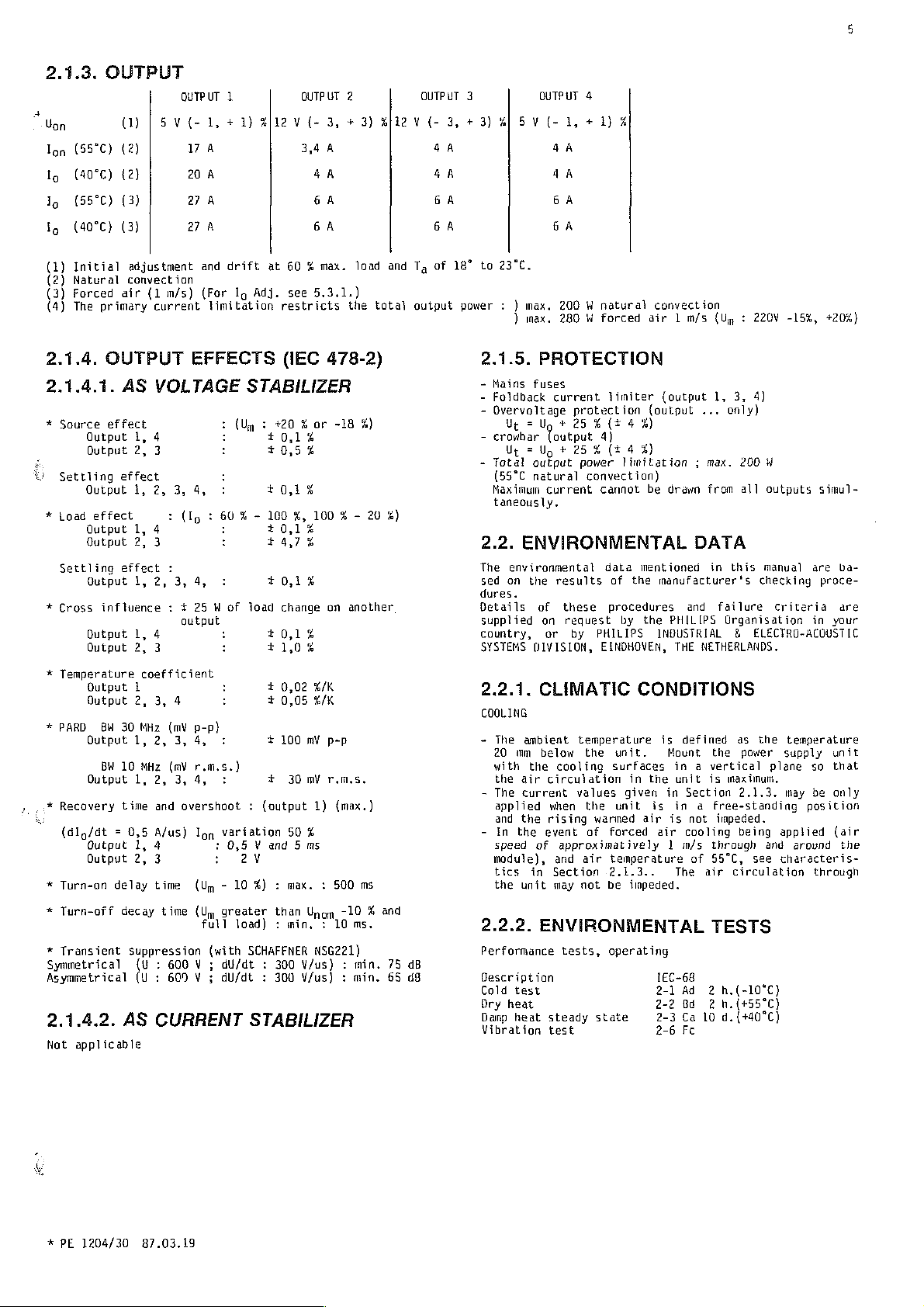
2.1.3.
4
Uon
lon
(55°C)
Ig
(40°C)
Ig
(55°C)
ig
(40°C)
(1)
Initial
(2)
Natural
(3)
Forced
(4)
The
OUTPUT
|
(1)
(2)
(2)
(3)
(3)
adjustment
convection
air
primary
(1
OUTPUT
(-
V
5
17
20
27
27
m/s)
current
1
1)
+
1,
À
À
À
А
and
drift
(For
Ig
limitation
Zl12
at
Adj.
OUTPUT
3,
(-
V
3,4
À
4
A
6
À
6
À
60 % max.
see
5.3.1.)
restricts
2
+
load
the
3)
g[i2
and
total
QUTPUT
3
5
#|
+3)
3,
(-
V
4A 4A
4A
6
A
6A
Tg
of
18°
to
23°C.
output
power
: )
)
OUTPUT
1,
(-
V
48
SA
GA
max.
200 W natural
max.
280 М forced
4
+1)
%
convection
air 1 m/s (Up : 220V
-15%,
+20%)
2.1.4.
2.1.4.1.
*
É -
È/
*
toad
*
Cross
*
*
PARD
. , Recovery
4
*
*
*
Symmetrical
Asymmetrical
2.1.4.2.
Not
OUTPUT
AS
Source
Settling
Settling
Temperature
Turn-on
Turn-off
Transient
effect
Output
Output
Output
Output
Output
Output
Output
Output
Output
Output
Output
Output
(dlg/dt = 0,5
Output
Output
1,
2,
effect
1,
effect
1,
2,
effect
1,
influence : +
1,
2,
1
2, 3,
BW
30
1,
BW 10
1,
time
1,
2,
delay
decay
suppression
(U : 600 V ;
(U : 600 V ;
AS
applicable
EFFECTS
VOLTAGE
4
3
2,
3,
4,
:
(Ig : 60 % -
4
3
:
2,
3,
4,
25 W of
output
4
3
coefficient
4
MHz
(mV
p-p)
2,
3, 4,
MHz
(mV
r.m.s.)
2,
3,
4,
and
overshoot : (output
A/us)
lon
4
3
time
time
:
:
(Um - 10
(Um
full
(with
CURRENT
(IEC
478-2)
STABILIZER
:
(Um : +20 % or
:
10,1%
:
10,5%
:
:
10,1%
100
%,
:
100 % -
10,1%
3474
:
+0,1%
load
change
:
+0,1%
:
t
1,0%
:
+
0,02
2
005
100 m р-р
+
30 mV
50
%
than
Unom
%/K
EK
1)
:
:
è
:
variation
0,5 V and 5 ms
24
#) : max. : 500
greater
load) : min. © 10
SCHAFFNER
dU/dt : 300
dU/dt : 300
STABILIZER
NSG221)
V/us) : min.
V/us) : min.
-18
x)
20
2%)
on
another Details
r.m.s.
(max.)
ms
-10 % and
ms.
75
dB
65
dB
2.1.5.
-
Mains fuses
-
-
-
PROTECTION
Foldback
Overvoltage
crowbar Toutput
current
protection
Up = Uy + 25%
Ur = Uy + 25%
Total
output
(55°C
natural
Maximum
taneously.
2.2.
The
sed
dures.
supplied
country,
SYSTEMS
2.2.1
COOLING
-
The
20
with
the
-
The
applied
and
-
In
speed
module),
tics
the
2.2.2.
Performance
Description
Cold
Ory
Damp
Vibration
current
ENVIRONMENTAL
environmental
on
the
results
of
these
on
request
or
by
DIVISION,
.
CLIMATIC
ambient
mm
below
the
cooling
air
circulation
current
the
the
unit
values
when
rising
event
of
approximatively 1 m/s
and
in
Section
may
ENVIRONMENTAL
tests,
test
heat
heat
steady
test
limiter
(140%
4)
(54%)
power
limitation ; max.
convection)
cannot
data
of
the
procedures
by
PHILIPS
EINDHOVEN,
temperature
the
unit.
surfaces
in
given
the
unit
warmed
of
forced
air
temperature
2.1.3..
not
be
impeded.
operating
state
(output
(output
be
drawn
1,
...
from
3,
only)
200
all
4)
W
outputs
DATA
mentioned
manufacturer's
the
INDUSTRIAL & ELECTRO-ACOUSTIC
CONDITIONS
is
the
is
air
air
in
this
manual
checking
and
THE
NETHERLANDS.
failure
Organisation
PHILIPS
I
defined
Mount
in a vertical
unit
in
Section
in a free-standing
is
not
cooling
The
of
air
is
through
55°C,
as
the
power
maximum,
2.1.3.
impeded.
being
see
circulation
the
plane
and
criteria
temperature
supply
may
position
applied
around
characteris-
TESTS
IEC-68
2-1
Ad 2 h.(-10°C)
2-2
Bd 2 h.{+55°C)
2-3
Ca
10
Fc
d.{+40°C)
2-6
simul-
are
ba-
proce-
are
in
your
unit
so
that
be
only
(air
the
through
*
PE
1204/30
87.03.19
Page 10

Page 11

Tests
for
storage
Description
Cold
test
Dry
heat
Vibration
Bump
Cyclic
test
test 2-29
damp
heat
test
Packaging
The
test
of
the
relevant
2.3.
MECHANICAL
2.3.1.
methods
OVERALL
mentioned
150-Standards.
MASS
For
Euromodule
Height : 233,4
Width
:
Depth : 174,0
Mass
:
2.3.2.
Rack : DIN
Comecting
X9001
X901
18
7,
mm
93,0
mm
mm
2,7
kg
MOUNTING
41494
(6
Block
DIN
DIN
:
41612
41612
and
transport
1EC-58
2-1
2-2
2-6
2-30
90 - 100 % RH
according
DATA
DIMENSIONS
6U
(without
U)
F32M
HI5M
are
LED)
Ab
72
Bb 96
Fe
Eb
Ob
in
h.{-40°C)
h.(+70°C)
21
d.(+25°C
to
UN-D-1400
accordance
ta + 40°C)
with
AND
those
3.2.
MOUNTING
The
power
by-side 19-inch
supplies
in
accordance
are
rack-mounting
with
DIN
Height : 6 U
Eurocard : 233,4
The
mains
the
principal
to
the
instruction : Fig.
Table 1 gives a survey
of
suitable
connectors
To
maintain
the
rack
{mounting
PE
fans
for a 220 V a.c.
3.3.
below
1373/02
for a 110
DISMANTLING
SEE
WARNING B -
mm x 160
filter
height : 1U,
to
and
mains
racks
X901
the
must
ambient
55°C,
one
Va.c.
mains.
connector
and
or
-
Removal
and
-
adjustments
access
:
are
INSTRUCTIONS
intended
41494
mm
be
mounted
700.
of
together
X9001.
temperature
the
PHILIPS
width : 19
two
mains
Before
first
sources
or
discharge
resistor
accessible
for
using
:
as
of
the
manufacturers,
with a survey
fan
inch rack
fans
PE
and two
handling
disconnect
and
wait 4 minutes,
with a wire-wound
(isolated)
without
individual
the
Eurocard
near
equipment according
of
the
unit
as
passible
type
indication
of
instrument
is
recommended
adaptor)
or
grooves
1374/02 : one
series-connected
or
dismantling
from
all
voltage
of
100
kOhm.
dismantling
side-
female
or
two
fans
t
to
in
4
+
2.4.
ACCESSORIES
2.4.1.
2.4.2.
PE
PE
PE
PE
PE
PE
OPERATING
OPTIONAL
1373/02
1374/02
1390/04
1390/16
1390/40
1390/45
Rack
Fan
Key
Front
Safety
EMI
DIRECTIONS
3.
INSTALLATION
3.1.
INITIAL
Refer
to
Safety
SEE
WARNING A -
Before
building
protective
to be
Connect
connecting
installation,
verified.
power
-
connecting
earth
adaptor
for 2 fans
(110 Y a.c.)
set
(Manual
plate
20
shield
shield
(Manual
FOR
INSPECTION
Precautions
PROTECTIVE
the
equipment
the
lead
of
supply
to a protective
black
X901
MANUAL
4822
T, 6 U
(Manual
4822
USE
and
EARTHING
proper
the
building
terminal
872
40142)
(Manual
4822
872
872
Unpacking
to
the
functionning
earth
32z.
4822
872
40385)
40386)
mains
installation
with
:
40155)
of
of
need
the
the
3.4.
SENSING
NOTE : Bear
sensing
wer
duce
As
can
30
3.4.1.
See
On
sensing.
Output
Output
are
Supply
the
output
soon
as
be
reset
seconds.
LOCAL
Fig.
224
delivery,
1[X901 ( 42)|x901
41X9001
3.4.2.
See
Remote
drops
ce
must
Remove
Connect
Maximum
see
REMOTE
(Only
Fig.
230
sensing
in
the
from
the
be
defined
:
3.4.1.
(screened) : (output
voltage
also Sect.
in
mind
incorrectly
may
not
voltages
the
fault
by
interrupting
the
For
local
+
SENSE
(29z) | X9001
for
output
can
load
power
on
Connections
drop
3.5.
CONNECTIONS
that
if
the
connected
operate
to
is
eliminated,
correctly
zero.
the
SENSING
power
supply
sensing,
connect
(18d)
(24b)
SENSING
1,
4)
be
usefully
lines,
when
supply
the
(output
in
for
the
or
if
load.
as
for
1)
4)
each
of
connections
links
for
interrupted
or
the
the
for a minimum
connected
to
is at
output
sensing,
local
OVP
output
compensate
some
characteristics
or
mains
is
not
employed
load
the
local
X901 ( 4z) and "+"
x901
(18d)
X9001
X9001
the
load
to
and
(24z)
and
(240)
and "-"
lines : 0,2 Y ;
the
load,
or
will
for
see
"-"
"+"
remote
the
voltage
local
distan-
Sect.
load
load
load
load
po-
re-
of
for
*
PE
1204/30
87.03.19
Page 12

Page 13
NOTE : The
influenced
sense
characteristics
To
maintain
improve
capacitor
recommended
sense
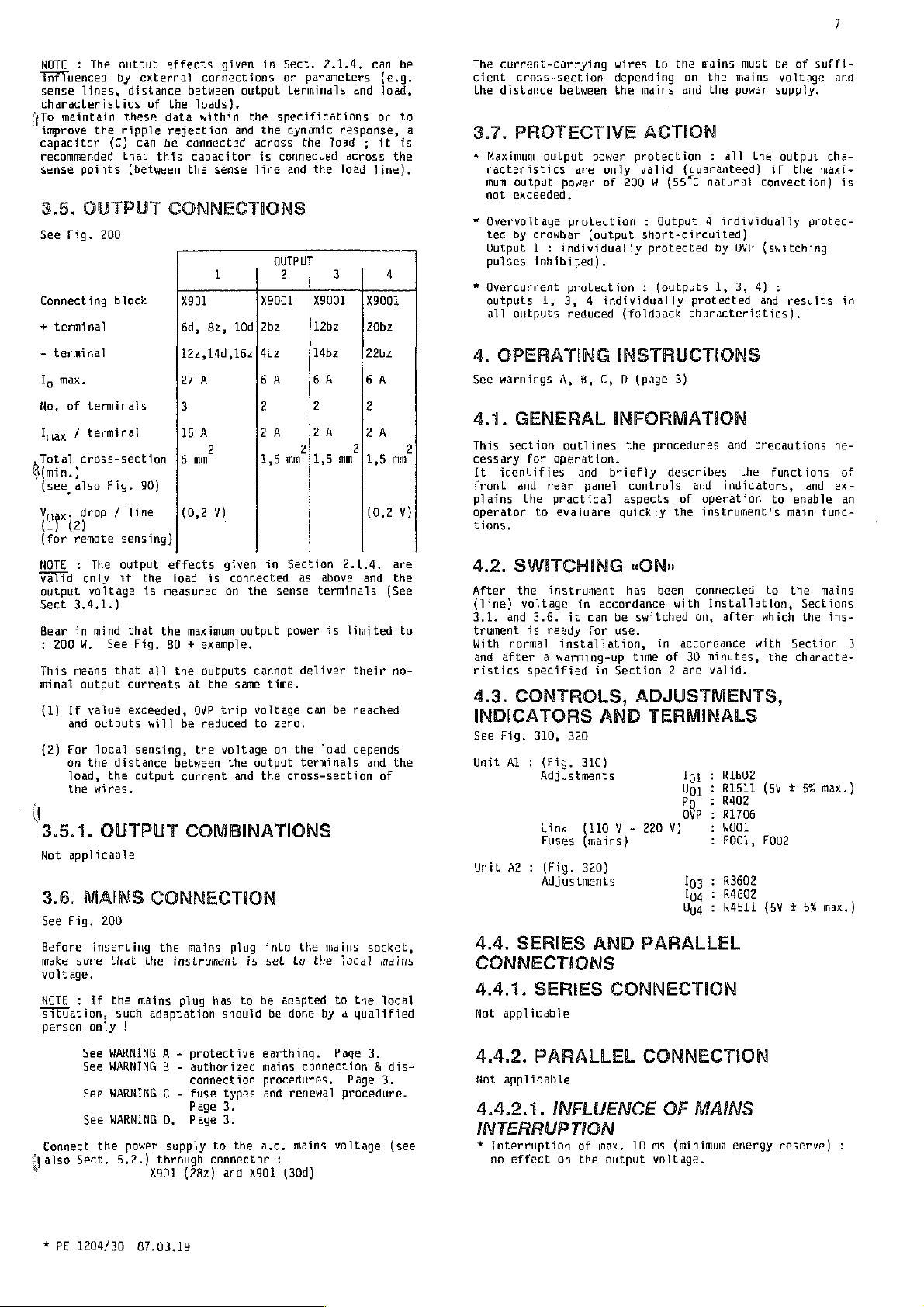
3.5.
See
Fig.
Connect
+
terminal
-
terminal
Ig
max.
No.
of
output
by
lines,
the
ripple
(C)
points
OUTPUT
200
ing
block
terminals
Imax / terminal
Tatal
cross-section
min.)
(see
also
Fig.
Vmax:
drop / line (0,2
(ia)
(for
remote
NOTE : The
valid
output
Sect
3.4.1.)
Bear
:
2004.
This
means
minal
(1)
If
and
{2)
Рог
on
load,
the
only
voltage
in
mind
output
value
outputs
the
wires.
sensing)
output
if
See
that
local
distance
the
q
3.5.1.
Not
3.6.
See
Before
make
voltage.
NOTE : if
Situation,
person
OUTPUT
applicable
MAINS
Fig.
200
inserting
sure
that
the
such
only
effects
externa]
distance
of
the
these
data
rejection
can
be
that
this
(between
CONNECTIONS
:
90)
effects
the
load
is
measured
that
the
Fig.
80 + example.
al]
the
currents
exceeded,
will
sensing,
between
output
CONNECTION
the
the
instrument
mains
adaptation
!
given
in
connections
between
loads),
within
capacitor
sense
1
8z,
À
and
10d]
connected
the
X901
6d,
122,14d,16z|4bz
27
3
ISA
2 2
{6
mm
V)
Sect.
or
output
terminals
the
specifications
the
dynamic
across
is
connected
line
and
OUTPUT
2 3 4
X9001
2bz
6A 6A
2 2
2A
1,5 mm
given
in
the
cannot
time.
voltage
to
output
is
set
be
be
Section
as
sense
power
deliver
zero.
on
the
terminals
cross-section
the
to
adapted
done
is
connected
on
maximum
at
be
current
outputs
the
OVP
trip
reduced
the
voltage
output
same
the
and the
COMBINATIONS
mains
plug into
plug
has
to
should
2.1.4,
parameters
the
the
|X9001
12bz
1407
2A
(1,5
can
be
(e.g.
and
load,
or to
response,
Toad ; it is
across
load
the
line),
|X9001
20bz
22bz
6A
2
2A
2
mm
11,5
mm
(0,2
V)
a
2
2.1.4.
above
terminals
is
can
be
load
mains
the
local
to
by a qualified
and the
limited
their
reached
depends
and
of
socket,
mains
the
local
are
(See
to
no-
the
The
cient
the
3.7.
*
*
*
4.
See
4.1.
This
cessary
It
front
Plains
operator
tions.
4.2.
After
(line)
3.1.
trument
With
and
ristics
4.3.
INDICATORS
See
Unit
Unit
4.4.
CONNECTIONS
4.4.1.
Not
current-carrying
cross-section
distance
between
PROTECTIVE
Maximum
racteristics
mum
not
Overvoltage
ted
Output 1 :
pulses
Qvercurrent
outputs
all
output
output
exceeded.
by
outputs
power
crowbar
individually
inhibited).
1,
are
pratection : Output 4 individually
protection : (outputs
3, 4 individually
reduced
OPERATING
warnings
A,
GENERAL
section
identifies
for
and
the
to
outlines
operation,
and
rear
practical
evaluare
SWITCHING
the
instrument
voltage
and
is
normal
after a warming-up
specified
in
3.6.
it
ready
installation,
CONTROLS,
Fig.
310,
320
Al : (Fig.
Adjustments
Link
Fuses
A2 : (Fig.
Adjustments
SERIES
SERIES
applicable
wires
depending
the
mains
ACTION
power
protection : all
only
valid
of
200 W (55"C
(output
short-circuited)
protected
(foldback
INSTRUCTIONS
8,
C, D (page
INFORMATION
the
briefly
panel
controls
aspects
quickly
«ON»
has
accordance
can
be
for
switched
use.
time
in
Section 2 are
ADJUSTMENTS,
AND
310)
que Y -
(mains)
320)
AND
TERMINALS
220
PARALLEL
CONNECTION
to
the
mains
on
the
and
the
(guaranteed)
natural
by
1,
protected
characteristics).
3)
procedures
describes
and
of
operation
the
instrument's
been
connected
with
Installation,
on,
in
accordance
of
30
minutes,
valid.
Ipi : R1602
101 : R1511
Po : R402
ove : R1706
V)
:
:
103 : R3602
104 : R4602
404 : 24511
must
mains
power
the
if
convection)
OVP
(switching
3,
4)
and
and
precautions
the
indicators,
after
WOOL
F001,
functions
to
to
which
with
the
(5V + 5%
F002
(5\ + 5%
be of
voltage
supply.
output
the
:
results
and
enable
main
the
Sections
the
Section
characte-
suffi-
and
cha-
maxi-
is
protec-
in
ne-
of
ex-
an
func-
mains
ins-
3
max.)
max.)
Connect
Spalso
у
*
PE
See
WARNING A -
See
WARNING B -
See
WARNING C -
See
WARNING
the
Sect,
1204/30
power
5.2.)
87.03.19
D.
supply
through
X501
protective
authorized
connection
fuse
types
Page
3.
Page
3.
to
the
connector
(282)
and
earthing.
mains
procedures.
and
renewal
a.c.
mains
:
X901
(30d)
Page
connection 4 dis-
3.
Page
3.
procedure.
voltage
(see
4.4.2.
Not
4.4.2.1.
PARALLEL
applicable
INFLUENCE
INTERRUPTION
*
Interruption
no
effect
on
of
the
CONNECTION
max.
10
output
OF
ms
(minimum
voltage.
MAINS
energy
reserve)
:
Page 14

Page 15
4.5.
EXTERNAL
4.5.1.
Not
4.5.2.
REMOTE
applicable.
ENERGY-RESERVE
(PWF)
See
Fig.
267
4.5.2.1.
TAGE
When a power
comprising
tatile)
ruption
information.
It
is
mation
search
ply
voltage)
gress
ting
Jo
enabie
receive a signal
the
preceding
The
"PWF"
that
If
the
(high
“turn-on
switching
ply
for
more
These 5 ms
memory
ting
Connect
circuit
d.c.)
"-"
X9001
The
signal
-
the
The
signal
-
the
tion).
-
the
output).
The
signal
energy
is
OFF.
5.
ADJUSTMENTS
5.1.
WARNING D :
type-plate
APPLICATIONS
OF
THE
supply
peripheral
memories, a voltage
or
cut-out)
in
the
user's
in
non-volatile
it
or
to
(e.g.
the
power
meets
TTL
is
the
between
output
jnersy
output voltage
See
ly.
handling.
The
operating.
or
for
peripheral
this
supply
the
voltage
signal
these
power
supply
level) ; hence
delay
on)
no
to
reserve
and
longer
than 5 ms.
will
the
non-volatile
peripheral
the
external
with
an
terminals
(28z)
is
"HIGH"
voltage
switches
reserve
remains
WARNING B -
After
adjustment
GENERAL
when
must
CONTROLS
ON-OFF
POWER
is
equipment
may
interest
reintroduce
to
save
ending
equipment
operation
announcing
is
going
drop.
or
power
criteria,
works
time”
it
becomes
capable
serve
to
equipment.
device
impedance
and
"+"
when
is
from
is 5 ms
disappears
"LOW"
is
equal
adjustments
switching
of
changing
be
suitably
INDICATION
AND
RESERVE
used
for
feeding a digital
or
drop
occasion
to
memories
it
the
the
reading
to
to
reserve
normally, a voltage
the
(between
of
enable
memory
higher
:
Xx9001
:
nominal
"HIGH"
(for
to
zero
off
Ug
and
the
amended.
(volatile
(supply voltage
a
put the
(so
after
access
that
delivering
of
of a sector
into
neutral
continue,
the
disappear,
indication
signal
0,6
“low",
when
transfer
(disk)
(one
gate
than
(30b)
(Power
level
minimum
(e.g.
TTL
74/LS
or
if
by
qualified
wait 4 minutes
То
may
nominal
ADVAN-
OR
or
loss
of
important
as
to
return
is
and
to
(worst-case
short-circuited
be
values,
be
of
memories
position).
the
system
output
voltage
i.e. a signa
is a signal
is
"high"
1,1 sec
the
power
its
rated
from
the
or
for
TTL
74/LS
100
kOhm
ON}.
“LOW"
logic)
the
power
person
executed
the
PWF
system
non-vo-
inter-
data
infor-
able
the
in
or
present
after
buffer
reset-
for
when
condi-
when
supply
before
while
rating
or
sup-
pro-
put-
must
of
the
after
sup-
power
or
5 ¥
:
the
on-
to
5.2.
MAINS
See
Fig.
200
On
delivery,
For 110 V a.c.,
Remove
fuses
5.3.
OUTPUT
Ail
the
values
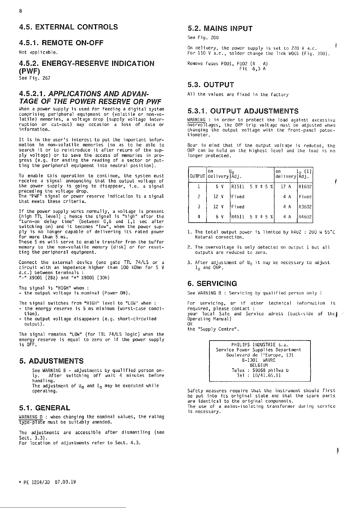
5.3.1.
WARNING : in
overvoitages,
changing
tiometer.
Bear
OVP
longer
QUTPUT | delivery
1.
2.
a
3.
6.
See
For
required,
your
Operating
OR
the
Safety
be
are
The
is
OUTPUT
the
in
mind
can
be
protected,
on
i
2
3
4 5
The
total
Natural
The
overvoltage
outputs
After
adjustment
lo
and
SERVICING
WARNING 8 :
servicing,
local
"Supply
measures
put
into
identical
use
of a mains-isolating
necessary.
INPUT
the
power
sotder change
FOUL,
FUO2
Fit
are
fixed
order
ta
the
OVP
output
that
held
SV
12 Y [Fixed
12 Y [Fixed
VO
output
convection.
are
OVP,
please
Sale
Manual)
Centre".
Service
its
voltage
if
on
the
Up
|Adj.
JRISIL 5 V+t5%|
[RASII
power
is
reduced
of Uy
Servicing
or
if
contact
and
PHILIPS
Power
Boulevard
B-1301
Telex : 59058
Tel : 10/41.65.11
reguire
original
to
the
original
supply
(4 A)
6,3
À
in
the
is
the
factory
set
link
ADJUSTMENTS
pratect
trip
the
only
to
Service
voltage
with
output
highest
5Vt5%
is
limited
detected
zero.
it
may
by
qualified
other
:
INDUSTRIE
Supplies
de
l'Europe,
WAVRE
BELGIUM
that
the
state
the
load
must
the
voltage
level
on
delivery|Adj.
1
on
be
necessary
technical
adress
5.a.
Department
philwa
instrument
and
that
components
transformer
to
220 V a.c.
W001
(Fig.
against
be
front-panel
and the
Α
AA
AA
AA
by
R4U2 : 200 W 55°C
output 1 but
persan
(back-side
131
b
excessive
adjusted
is
reduced,
load
Ig
(1)
|R1602
[fixed
183602
|RA602
to
adjust
only
information
should
the
spare parts
during
310).
when
poten-
the
is
no
ali
|
is
of
the)
first
service
.
'
,
The
Sect.
For
*
PE
location
adjustments
3.3).
of
1204/30
87.03.19
are
accessible
adjustments
refer
after
to
dismantling
Sect.
4.3.
(see
Page 16

Page 17
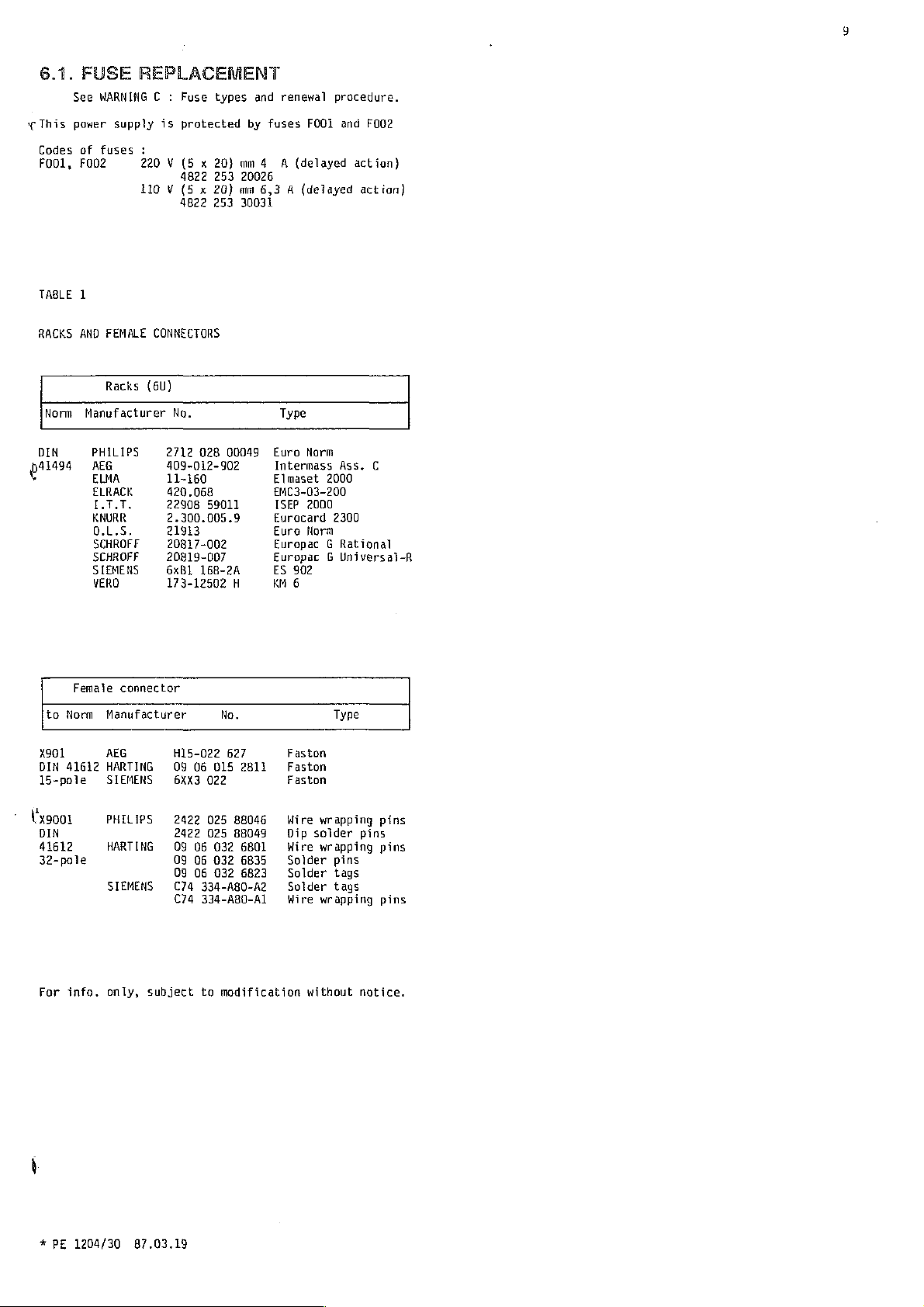
6.1.
«This
Codes
Fool,
TABLE
RACKS
FUSE
See
WARNING C :
power
of
fuses
F002
1
AND
FEMALE
REPLACEMENT
Fuse
supply
is
protected
:
220 V (5 x 20}
4822
110 V (5 x 20)
4822
CONNECTORS
types
253
253
and
renewal
by
fuses
mm 4 A
(delayed
20026
mw
6,3 A (delayed
30031
FOO1
procedure.
and
F002
action)
action)
Norm
DIN
041494
+
to
x901
DIN
15-pole
1
Vx9001
DIN
41612
32-pole
Racks
Manufacturer
PHILIPS
AEG
ELMA
ELRACK
ITT.
KNURR
0.1.5,
SCHROFF
SCHROFF
SIEMENS
VERO
Female
Norm
Manufacturer
AEG
41612
HARTING
SIEMENS
PHILIPS
connector
HARTING
SIEMENS
(6U)
No.
2712
409-012-902
11-160
420.068
22908
2.300.005.9
21913
20817-002
20819-007
6xB1
173-12502
H15-022
09
6XX3
2422
2422
09
09
09 06
C74
C74
Type
028
00049
Euro
Intermass
Elmaset
59011
16B-2A
No.
06
015
022
025
025
06
032
06
032
032
334-A80-A2 9 Solder
334-A80-A1
EMC3-03-200
ISEP
Eurocard
Eura
Europac G Rational
Europac G Universai-R
ES
KM
Faston
Faston
Faston
Wire
Dip
Wire
Solder
Solder
902
6
H
627
2811
88046
88049
6801
6835
6823
Wire
Norm
2000
2000
2300
Norm
Type
wrapping
solder
wrapping
pins
tags
tags
wrapping
Ass.
C
pins
pins
pins
pins
For
*
PE
info.
1204/30
only,
subject
87.03.19
to
modification
without notice
Page 18

Page 19
10
INHALTSVERZEICHNIS - --
LISTE
DER
ABBILDUNGEN - - -
-----++-+-------
- - - - - - - - - - - -
ABKÜRZUNGEN - - - + - + + + - - - -
SICHERHEITSYORKEHRUNGEN
ZEICHEN
BEEINTRACHTIGTER
WICHTIGE
WARNUNG
WARNUNG
WARNUNG
AUSPACKEN
WARNUNG
WARNUNGEN
A
B
C
O
SICHERHEITSSCHUTZ
-
ーー
ニニ
ーー
ALLGEMEINES - ----------+--------+-
1.
2.
2.1.
2.1.1.
2.1.2.
2.1.3.
2.1.4,
2.1.4.1.
2.1.4.2,
2.1.5.
2.8.
2.2.1.
2.2.2.
2.3.
2.3.1.
2.3.2.
2.4.
2.4.1.
2.4.2,
EINLEITUNG
BESCHREIBUNG
ELEKTRISCHE
ALLGEME
INES
DATEN
EINGANG
AUSGANG - -
- + -
AUSGANGSSTABILITAT
BETRIEB
BETRIEB
SCHUTZSCHAL
ALS
SPANNUNGSSTABILISATOR
ALS
STROMSTABIL
TUNGEN
UMWELTANGABEN
KLIMATISCHE
BEDINGUNGEN
UMWELTTESTS
MECHANISCHE
GESAMTMASSE
MONTAGE
DATEN
UND
MASSE
ZUBERÙR
BEDIENUNGSANLE I TUNG
OPTIONEN
- -
- - - -
(IEC
478-2)
ISATOR
- - - - - - - - - - - - - 14
10
10
- - - - - - - - 10
ニー
ニー
ニー ニー
ニーー
11
12
+ -
- - - - - 13
LISTE
DER
ABB.
80
PE
200
Externe
224
Lokalflinlen
230
Fernfühlen
267
Energiereserve
310
Al-Einheit
320.
AZ-EinhBit
541
Hochspannungstest
700
Anschluss
1000
Schaltbild
ABBILDUNGEN
1204/30
Anschlüsse
..................
...............
...........
eines
cece
Ausgangscharakteristik
...........
KK
.ev
ee
(TTt-Signal)
..................
0
0000400000000
................
externen
cece
Netzfilters
eee
κε
00 v né
000...
.........
κκ
teens
ーーー
レー
29
26
26
26
26
27
28
29
29
30
GEBRAUCHSANWEISUNGEN - - - -
3.
3.1.
3.2.
3.3.
3.4.
3.4.1.
3.4.2,
3.5.
3.5.1.
3.6.
3.7.
4.
4.1.
4.2.
4,3.
INSTALLATION
ERSTINSPEKTION
MONTAGEANHE
DEMONT
VERBINDUNGEN
ISUNGEN
AGE
FUR
LOKALFUHLEN
FERNFUHLEN
VERBINDUNGEN
KOMBINATIONEN
VERBINDUNGEN
AM
AUSGANGSSEITIG
NETZSEITIG
SCHUTZSCHALTUNGEN
BED
IENUNGSANLE 1 TUNG
ALLGEMEINE
HINWEISE
EINSCHALTEN
STEUERFUNKTIONEN,
AUSGANG - - -
KLEMMEN
4.4.
4.4.1,
4.4.2.
4.4.2.1.
4.5.
4.5.1,
4.5.2.
4.5.2.1.
5.
5.1.
5.2.
5.3.
5.3.1.
6.
6.1.
TABELLE 1 :
REIHEN-
RETHENSCHAL
UND
PARALLELSCHAL
TUNG
PARALLELSCHALTUNG
NETZUNTERBRECHUNGSEFFEKT
EXTERNE
FERNBEDIENTES
ANZEIGE
ANWENDUNG
(NETZAUSFALL
STEUERFUNKTIONEN - - - - ~ - - - -
EIN-AUS
DER
ENERGIERESERVE
UND
VORTEILE
)
EINSTELLUNGEN
ALLGEME
INES
NETZEINGANG
AUSGANG
EINSTELLUNGEN
AM
MARTUNG
ERSETZEN
VON
SICHERUNGEN
GESTELLAUFBAU
------------
SENSING
(FERNFUHLEN)
EINSTELLUNGEN,
TUNG
(NETZAUSFALLSIGNAL)
DER
ENERGIERESERVE
AUSGANG
- - - - - - - - - 17
UND
STECKDOSEN
14
- - - - - - - 15
ANZEIGEN
UND
16
- -
~ - - - 17
ABKURZUNGEN
ADd
Bu
E
Fn
fm
6
In
16
lan
15
M
M-S
OVP
PARD
Pa
p-p
Pur
RS
rms.
Rp
5
T
Ta
tr
Un
Uomax
Va
Von
Up
Ut
Einstel
lung
Bandbreite
Stapeleinheit
Funktion
Netzfreguenz
Externes
(Höhe)
Gerët
Netzstrom
Ausgangsstrom
Nennausgangsstrom
Lokalfiihlen
Master
Master-S
Uberspannungsschutz
lave
Stürspannung
Ausgangsleistung
Spitze/Spitze-Wert
Netzausfall-Anzeige
Fernfiúhlen
(Remote
Effektivwert
Progr
anmierungswiderstand
Slave
Teileinheit
Umgebungs
(5,08
temperatur
Energiereserve-Zeit
Netzspannung
Maximale
Ausgangsspannung
Ausgangsspannung
Nennausgangsspannung
Progr
ami
ers
Ansprechspannung
pannung
für
DEN
41494
Sensing
mm) DIN
41494
Uberspannungsschutz
*
PE
1204/30
87.03.19
Page 20

Page 21
Page 22

Page 23
12
ALLGEMEINES
1.
EINLEITUNG
Die
PE
Gleichstromversorgungs-Module
Sie
sprechend
Der
Uberstromschutz
Sonstige
-
-
~
=
HINWEIS : Das
wickelt
das
tung
sen.
garantierte
Zahlen
kénnen
2.
Dieser
hinsichtlich
plituden,
pekte
chanischen
Liste
rät
2.1.
Die
des
Lieferung
23°C
1204/30 (offene
sind
normalerweise
der
Norm
DIN
Uberspannungsschutz
ist
einstellbar.
Lokal-
PNF
(TTL-Pegel)
vorhandene
und
Miglichkeiten
Fernfühlen
Uberspannungsschutz
Crowbar
Design
und
Nur
ohne
nicht
verbessert
im
Vergleich
Informationen
Werte
Daten
Toleranzen
garantiert
mit
Toleranzen
betrachtet
Gerdt
gegebenen
BESCHREIBUNG
Teil
enthélt
die
Eingangs-
Einstellung,
und
Störpegel.
und
mit
geliefert
Umweltdaten
den
Zubehorteilen
werden,
ELEKTRISCHE
in
diesem
nominalen
bei
Teil
angegebenen
Betriebsbereichs
ist
das
Gerit
Konvektionskiihlung
als
41494
dieses
werden,
zu
haben
werden.
technischen
und
Stabilitàt
Ferner
auf
Version)
mit
steckbare
(6 E Hohe)
ist
fest
sind
mehrerenAusgángen.
Einbaugerát
vorgesehen,
eingestelit
:
den
werden.
Netzgerdts
in
dieser
leichte
oder
nur
kann
Aus
diesem
Bedienungsanlei-
Anderungen
Grenzen
Informationswert
Daten
Ausgangsbedingungen
usw,),
werden
gegeben ; es
bei,
Einzelheiten
die
liegt
mit
DATEN
Werte
gelten
(0°C
eine
eingestellt.
bis + 55°C).
Umgebungstemperatur
stabilisierte
ent-
und
der
weiterent-
Grund
kann
aufwei-
kônnen
als
und
des
Netzgerits
(d.h.
Am-
Sicherheitsas-
zu
me-
auch
diesem
eine
Netzge-
innerhalb
Bei
von
*
Hochspannungstest
Im
Werk
gen
-
-
-
-
Wenn
ist
tung
wurden
unterzogen
zwischen
zwischen
zwischen
zwischen
die
es
erforderlich,
enthaltenen
ce-Anieitung
formiert
ben
kann,
Im
Falie
80 % (IEC
*
Ausgangsanschliisse : Die
*
Störpeyel
Eingang : in
die
Gerdte
:
Primarkreis
Primár-
und
Sekundárkreis
den
Ausgängen
Hochspannungsteste
Anweisungen
nicht
werden,
Wiederhohlung
348,
beiliegt,
die
Ausgabe
Uberreinstimmung
oder
VDE
vorausgesetzt,
filter
0871
am
Eingang
Hersteller
EICHOFF : 12000/49
Ausgang : in
Ubereinstimmung
folgenden
und
Chassis
Sekundárkreis
und
Chassis
sich
wiederholt
an
die
zu
muss
die
erforderlichen
der
Teste
2,
Abschnitt
Ausgangsanschlilsse
bend
gegen
zwischen
schliisse
Gleichspannung
spannung
schreiten.
Entweder
mit VOE
(B)-Pegel,
es
wird
verwendet.
{zur
Information)
mit
Hochspannungsprifun-
:
1,5
kV
Wechselspannung
:
4
kV
Mechselspannung
:
1.
kv
:
halten.
Wechselspannung
500 V Wechseispannung
werden
in
der
Service-Anlei-
Wenn
eine
Servicestelle
Werte,
9.7.4.8).
die
Informationen
reduzieren
sind
Erde.
einem
und
Die
der
Ausgangsan-
Erde darf
oder
(r.m.s.)
der
"+"
für
ein
nicht
-Po]
oder
0875
(N-12)-Pegel
Netzrückwirkungen,
zusátzliches
Siehe
Abb.
:
IEC
478-3
sollten,
Servi-
in-
ge-
his
schwe-
Spannung
155
Wechsel-
über-
der
Netz-
700.
V
2.1.1.
*
In
IEC
0806, (wenn
IEC
In
besteht
schaften : -
ALLGEMEINES
Sicherheit
Ubereinstimmung
348,
IEC
601
Ubereinstimmung
das
{Kalss
Energiegefahr
Ausgangsspannung
435,
Gerát
1,
oder
-
Ausgangsspannung
Jeistungen
Beim
Gebrauch
dárausgang
Prüffinger
CSA
C22-2-143,
eines
nicht
direkt
überbrückt
C22-2-154 : CSA
{mit
BEMERKUNG : nach
nur
Netzspannungen
zwischen
UL
nen
VDE
Ableitstrom
max.
Einer
208 V und
478,
UL
544 : UL
Sicherungen) : Akte
0806
SELY : Reg.
(vom
0,5
der
mA
r.m.s.
Ausgänge
Chassis
werden.
Beitrag
601.1
Bei
Tabelle
der
des
Speisegeräts
IV € Par.
Anwendung
Isoliertransformator
Ableitstrom
0,5
mA
mit
der
IEC
Sicherheitsklasse 1 IEC
601,
gestapelt
Typ
A)
mit
IEC
380 / VDE
fiir
Ausginge
Gleichspannung}
von
Ausganges
240 Y (oder
berúhrbar
werden
künnen.
ausseren
der
CSA
CSA-C235-83
zwischen
254
V,
zulássig
(mít
E69576
Nr.
1060
zur
50
an
Hz
Erde}
(bei
die
bei
muss
zum
19.4-b.
IEC
65,
IEC
nötig
sein,
Uberschreitet.
VDE
0411,
VDE
wird).
0806,
mit
liber
über
folgenden
42,4 V (Scheitelwert
2,0 V und
VA) und
im
System
zulässig
sein,
darf
bzw.
Nr.
abgenommenen
erwägten
104 Y und
ausseren
Vol. 1 Abs.
:
Lieferung)
Schutzerde
UL
4
angeschlossen
Erdschlussstrom
601
oder
UL
wenn
der
65
0804,
VDE
Abs.
2.2.50,
Eigen-
Dauer-
mehr.
der
Sekun-
mit
dem
LEC
LR52263-2
Sicherungen)
Messmethoda
127 V oder
abgenomme-
nach
IEC
544
kann
ein
gesamte
2.1.2,
Netzspannung
Nominale
Netzfrequenz
Lejstungsaufnahme : 580
Einschaltstrom
EINGANG
(AC):
220 V (180 V -
:
110 V (
47
(Worst-Case) : max.
Hz - 63
VA
Wirkungsgrad : Nominal : 67
90 V -
Hz
%
264
140
60
V)
Y)
A
oder
durch
Umstecken.
*
PE
1204/30
87.03.19
Page 24

Page 25
13
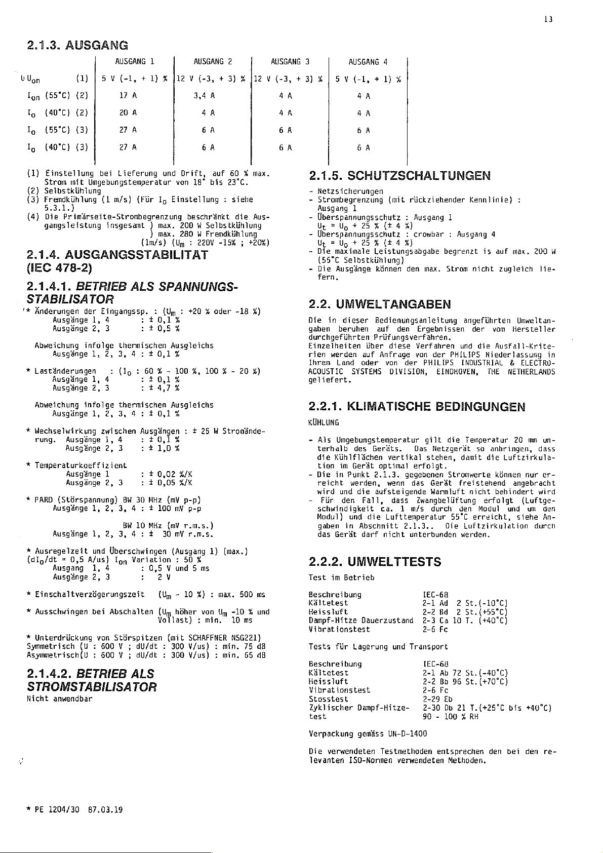
2.1.3.
AUSGANG
AUSGANG
U
Upon
Ton
(55°C)
lo
(40°C)
Ig
(55°C)
Ig
(40°C)
(1)
Einstellung
Strom
(2)
Selbstkiihlung
(3)
Fremdkihlung
5.3.1.)
(4)
Die
gangsleistung
2.1.4.
(IEC
2.1.4.1.
(1) | 5 v (-1, + 1) Z [12V
(2)
(2)
(3)
(3)
bei
mit
Umgebungstemperatur
(1
m/s)
Primérseite-Strombegrenzung
insgesamt ) max.
AUSGANGSSTABILITAT
478-2)
BETRIEB
STABILISATOR
*#
Anderungen
Ausgánge
Ausgánge
Abweichung
Ausgánge
*
Lastánderungen
Ausgánge
Ausgánge
Abweichung
Ausgänge
*
Wechselwirkung
rung.
*
Temperaturkoeffizient
*
PARB
Ausgänge
Ausgänge
*
Ausregelzeit
(dig/dt = 0,5
Ausgang
Ausgänge
*
Einschaltverzögerungszeit
*
Ausschwingen
*
Unterdriickung
Symmetrisch
Asymmetrisch(U
2.1.4.2.
der
Eingangssp. : (Um : +20 % oder
1,
4
2,
3
infolge
1,
2, 3, 4 :
1,
4
2,
3
infolge
1,
2, 3, 4 : + 0,1
Ausgánge
Ausgênge
Ausgánge
Ausgänge
(Störspannung)
zwischen
1,
2,
1
2,
1,
2,
1,
2, 3, 4 : + 30
und
Uberschwingen
A/us)
1,
4
2,
3
bei
Abschalten
von
(U
:
600 V ;
:
600 V ;
BETRIEB
:
Ion
Stůrspitzen
STROMSTABILISATOR
Nicht
anwendbar
1
YA
20
A
27
A
27
A
Lieferung
ALS
thermischen
und
(Für
Ig
)
max.
(lm/s)
SPANNUNGS-
:
10,1%
10,5%
10,1%
(lo : 6
:
thermischen
Ausgängen
4
:
+0,14
3
:
11,0%
+
3
BW 30
3, 4 : + 100
BW 10
0,02
+
0,05
MHz
MHz
Variation : 50%
:
0,5 V und 5 ms
2
(Um - 10
(Um
Vollast) : min.
dU/dt
:
dU/dt
:
ALS
AUSGANG
(-3,
+3) % |i2 V (-3,
3,4
À
AA AA
GA GA
GA GA
Drift,
von
Einstellung
200 W Selbstkühlung
280 M Fremdkiihlung
(Um : 2204
Ausgleichs
100
%
%
Ausgleichs
%
#/K
%/K
(mV
mV
(mV
mV
(Ausgang
V
hôher
(mit
300
300
auf
18°
bis
:
beschränkt
-15% ; +20%)
%,
100 % -
:
+
25 W Stromände-
p-p)
p-p
r.m.s.)
rims.
1)
(max.)
%) : max.
von
Um
SCHAFFNER
:
:
min.
min.
V/us)
Y/us)
2
60 % max.
23°C.
siehe
die
Aus-
-18
%)
20
%)
500
ms
-10 % und
10 ms
NSG221)
75 df
65
dB
AUSGANG
+3)
АА
3
4
AUSGANG
5
v(-1,
+1)
aA
4A
6A
6A
2.1.5.
-
-
-
-
-
-
2.2.
Die
gaben
durchgeführten
Einzetheiten
rien
lhrem
ACOUSTIC
geliefert.
2.2.1.
SCHUTZSCHALTUNGEN
Netzsicherungen
Strombegrenzung
Ausgang
Überspannungsschutz
Ut = Ug + 25 % (+4
1
Uberspannungsschutz
Ur = Ug + 25 Z (t
Die
maximale
(55°C
Selbstkühlung)
Die
Ausgánge
fern,
Leistungsabgabe
kónnen
UMWELTANGABEN
in
dieser
beruhen
werden
Land
Bedienungsanleitung
Prüfungsverfahren
iiber
auf
oder
SYSTEMS
KLIMATISCHE
KUHLUNG
-
Als
Umgebungstemperatur
terhalb
die
tion
-
Die
reicht
wird
-
Für
schwindigkeit
Modul)
gaben
das
2.2.2.
Test
Beschreibung
Kältetest
Heissluft
Dampf-Hitze
Vibrationstest
Tests
Beschreibung
Kaltetest
Heissluft
Vibrationstest
Stosstest
Zyklischer
test
Verpackung
des
Gerät
Punkt
werden,
die
Fall,
und
in
Abschnitt
darf
Geräts.
2.1.3.
aufsteigende
die
Kúhlfláchen
im
in
und
den
Gerát
UMWELTTESTS
im
Betrieb
Dauerzustand
für
Lagerung
Dampf-Hitze-
gemáss
4
%
(mit
rückziehender
:
Ausgand
%)
:
crowbar ; Ausgang
4%)
den
auf den
Anfrage
von
optimal
ca. 1 m/s
Lufttemperatur
nicht
diese
Verfahren
von
der
DIVISION,
Das
vertíkal
erfolgt.
gegebenen
wenn
das
dass
Zwangbelüftung
2.1.3..
unterbunden
und
Transport
UN-D-1400
Ergebnissen
Kennlinie)
1
begrenzt
inax.
Strom
nicht
angefiihrten
der vom
und
der
PHILIPS
PHILIPS
INDUSTRIAL & ELECTRO-
EINDHOVEN,
BEDINGUNGEN
gilt
die
Netzgerät
stehen,
Gerät
Warmiuft
durch
IEC-68
2-1
2-2
2-3
2-6
IEC-68
2-1
2-2
2-6
2-29
2-30
90 - 100 % RH
Temperatur
damit
Stromwerte
freistehend
nicht
den
55°C
erreicht,
Die
Luftzirkulation
werden.
Ad 2 St.{-10°C)
Bd 2 St.(+55°C)
Ca
10
T.
Fc
Ab
72
St.
Bb
96
St.
Fc
Eb
Db 21
T.(+25°C
4
is
auf
max.
zugleich
Hersteller
die
Ausfalt-Krite-
Niederlassung
THE
NETHERLANDS
so
erfolgt
Modul
(+40°C)
20
anbringen,
die
Luftzirkula-
kónnen
angebracht
behindert
und
(-40°C)
(+70°C)
bis
:
200
lie-
Umweltan-
in
mm
un-
dass
nur er-
wird
(Luftge-
um
den
síehe
An-
durch
+40°C)
W
*
PE
1204/30
87.03.19
Die
verwendeten
levanten
I50-Normen
Testmethoden
verwendeten
entsprechen
Methoden.
den
bei
den re-
Page 26

Page 27
14
2.3.
MECHANISCHE
2.3.1.
Für
Höhe : 233,4
Breite : 93,0
Tiefe : 174,0
Masse
2.3.2.
Baugruppentráger : DIN
Anschlussblock
2.4.
2.4.1.
2.4.2,
PE
PE
PE
PE
PE
PE
GESAMTMASSE
Euromodul
19
T, 6 E
mm
mn
mm
;
2,7
(ohne
kg
MONTAGE
41494
X9001
X901
DIN
DIN
41612
41612
F32M
15M
ZUBEHÓR
BEDIENUNGSANLEITUNG
OPTIONEN
1373/02
1374/02
1390/04
1390/16
1390/40
1390/45
Baugruppenträger
Ventilator
Stellungsschlitz
(Beschreibungsblatt
Frontplatte
(Beschreibungsblatt
Sicherheitsschirm
(Beschreibungsblatt
EMI
Schirm
(Beschreibungsblatt
{110 V AC)
20
Led)
T, 6 £
GEBRAUCHSANWEISUNGEN
DATEN
UND
(6
für 2 Ventilatoren
4822
4822
4822
4822
E)
872
872
872
872
MASSE
40142)
40155)
40385)
40386)
Das
Netzfilter
anschluss
der
Anweisungen : Abb.
Tabelle 1 gibt
se zu
passenden
Ubersicht
Um
die
halten,
empfohlen
zwei
für ein
toren
3.3.
Zu
3.4.
ANNERKUNG : Beachten
LokaT-
unterbrochen
arbeitet
die
Bobald
durch
wieder
Umgebungstemperatur
Ventilatoren
für
DEMONTAGE
SIEHE
-
Vor
zuerst
dartach 4 Minuten
-
(isoliert)
entfernen
-
Einstellungen
VERBINDUNGEN
oder
Spannung
der
Unterbrechung
eingaschaltet
3.4.1.
Siehe
Abb.
Bei
Lieferung
verdrahtet.
vorzunehmen
Ausgang
Ausgang 4|X9001
1|X901 ( 4z)
muss
der
Anlage
eine
Baugruppentrágern
der
Gegenstecker
wird
die
(Montagehtihe : 1£,
110
V-AC
220
V-AC
SICHERHEITSVORKEHRUNG
Handhabung
von
Oder
den
:
Fernfiihlen
werden,
bzw.
der
auf
Fehler behoben
LOKALFÜHLEN
224
ist das
Für
:
+
FUHLUNG
(247)
so
nah
wie
angeschlossen
700.
Ubersicht
PHILIPS-Ventilatoreinheit
PE
1374/02 : ein
und
zwei
verwenden.
jeder
warten.
Modul
von
100
sind
mbglich
miglich
der
X901
und
des
Geráts
Breite : 19")
in
Serie
B
oder
Auseinanderbau
Spannungsquelle
mit
kOhm
entladen,
ohne
FÜR
Sie,
dass
nicht
die
Uberspannungsschutz
OV
reduziert.
der
werden.
Lokalfühlen
-
X901
X9001
wenn
richtig
Stromversorgung
ist,
kann
Netzzuleitung
Gerât
für
sind
FUHLUNG
(18d)
(24b)
an
werden
Hersteller,
in
Verbindung
X9001.
unterhalb
oder
zwei
geschaïteten
abschalten
einen
Hrahtwiderstand
Demont
SENSING
die
Verbindungen
ausgeführt
ansprechen
die
Ausgangsspannung
fiir
Lokalfühlen
folgende
den
Hauptnetz-
nach
Massgabe
Typhinwei-
mit
55°C
PE
1373/02
oder
ein
Ventitatoren
Ventila-
das
age.
sind
nicht
richtig
kann
min.
30
Verbindungen
einer
zu
oder
Gerat
und
fiir
oder
und
sec
nicht
3.
INSTALLATION
3.1.
ERSTINSPEKTION
Siehe
auch
Sicherheitsvorkehrungen
SIEHE
SICHERHEITSVORKEHRUNG A -
Bevor
die
geschlossen
dellosen
Die
den
3.2.
Die
eines
ander
sind
Höhe
Eurokarte : 233,4
SIEHE
Anlage
Betrieb
Stromversorgung
über
:
-
Klemmleiste
MONTAGEANWEISUNGEN
Stromversorgung
einzelnen
in
einen
die
Fiihrungsschienen
WARNUNG A -
wird,
:16E
an
ist
zu
Geráts
19"
mm x 160
Schutzerdung
das
Versorgungsnetz
dessen
priifen.
ist
X90i
ist
Baugruppentrager
Schutzleiter
mit
einer
Klemm
so
konstruiert,
oder
mehrerer
gemâss
mm
322.
DIN
und
Auspacken
SCHUTZERDUNG
des
auf
Schutzerde
dass
Gerdte
moglich
41494
zu
Gebdudes
seinen
zu
verbin-
der
Einbau
nebenein-
ist.
benutzen.
an-
ta-~
Dazu
3.4.2.
Siehe
Die
Fallen
Dadurch
siert.
Zu
Abschnitt
Zu
Maximaler
Siehe
ANMERKUNG : Die
daten
(2.8.
schluss
werden,
Um
erhalten
halten
angebracht
densator
Lastleitung)
FERNFŮHLEN
(Nur
fir
Abb.
230
Flinlerteitungen
in
langen
wird
die
entfernen
verbinden
3.4.1.
(Ausgang
(Ausgang
diese
4)
Spannungsverlust
ebenfalis
kónnen
Senseleitungen,
und
Daten
oder
zu
verbessern,
werden.
Über
(abgeschirmt)
1)
Last,
angeschlossen
Ausgang
Speiseleitungen
X901 ( 42)
X901
X9001
X9001
Abschnitt
in
durch
innerhalb
um
die
1, 4)
dienen
Spannung
Verbindungen
(18d)
(24z)
(24b)
Abschnitt
externe
Entfernung
Eigenschaften
die
Stirspannung
kann
Es
wird
Sense-Punkte
zum
Ausgleich
zwischen
direkt
3.5.
der
im
für
:
und
"+"
und
und
und
in
wird.
Last
“-"
Last
"+"
Last
"-"
jeder
fiir
2.1,4.
Verbindungen
der
Spezifikationen
und das
ein
Kondensator
empfohlen,
(zwischen
von
Spannungsab-
Gerät
Verbraucher
Lokalfühien,
Last
Zuleitung : 0,2
Verbindungen
angegebenen
oder
zwischen
Ausgangsan-
Last)
beeinflusst
aufrechtzu-
dynamische
über
dass
dieser
Senseleitung
und
Last
stabili-
siehe
Y.
zur
Last
Ausgangs-
Parameter
Ver-
die
Last
Kon-
und
;
*
PE
1204/30
87.03.19
Page 28

Page 29

3.5.
VERBINDUNGEN
Siehe
Abb.
200
Klemmleiste
+
Anschluss
-
Anschluss
Maximaler
strom
Anzahl
Imax
punkt
Gesamtquerschnitt
(min.)
(Siehe
Max.
pro
(Für
ANMERKUNG : Die
sind
ben
messen
ANMERKUNG : Beachten
gabe
Dies
Leistung
(1)
(2)
3.5.1.
Ausgangs-
Klemmen
pro
Anschluss-
auch
Abb.
90)
Spannungs
Leitung
Fernfühler)
nur
angeschlossen
begrenzt
bedeutet,
Wird
punkt
die
Bei
Entfernung
Last,
leitungen
abf
al
(1)
(2)
dana
wird.
zur
der
des
Ausgangsspannungen
Lokalfiihlen
vom
in
gúltig,
ist
dass
gleichen
Wert
Uberspannungsschutzes
zwischen
Ausgangsstram
ab.
KOMBINATIONEN
SEITIG
Nicht
anwendbar
3.6.
VERBINDUNGEN
Siehe
Abb.
200
Vor
Einschieben
sicherstellen,
nung
eingestellt
ANMERKUNG : Muss
tuation
einer
Die
wechselspannung
X901
Die
Querschnitt
umgerůstet
qualifizierten
SIEHE
SIEHE
SIEHE
SIEHE
Stromversorgung
(282)
stromführenden
des
dass
ist.
MARNUNG A -
MARNUNG B -
WARNUNG C -
WARNUNG D -
(siehe
400
8901
haben.
AM
AUSGANG
1
X901
64,
82,
12z,14d,167|4bz
[27
A
3 2 2 2
}15
À
2
6
mm
(0,2
ν)
Abschnitt
wenn
ist,
und
Sie,
auf
dass
200
W.
nicht
alle
Zeit
abgeben
überschritten,
werden
hângt
die
den
AUSGANG
2 3
X9001
1091252
6A
ZA 2A 2А
1,5
2.1.4.
die
Last
an
den
die
Siehe
Ausgänge
auf
Spannung
Ausgangsanschliissen
und
vom
FX9001
1262
14bz 22bz
6A 6A
2 2 2
mm
(1,5
angegebenen
wie
oben
Senseanschlüssen
maximale
Abb,
BO + Beispiel.
künnen.
so
ihre
kann
der
erreicht
Nut]
der
Querschnitt
AUSGANGS-
NETZSEITIG
Netzsteckers
das
Gerát
der
Netzstecker
werden,
Leitungen
so
Person
Schutzerdung : Seite
Zulássiges
Abtrennen
Sicherungen
Seite
Seite
mittels
auch
(300)
in
auf
die
auf
darf
11
11
des
Steckers
miissen
diese
Anschliessen
vom
und
einen
vorgenommen
Abschnitt
die
Netzsteckdose
tirtliche
die
Arbeit
werden
Netz : Seite
Auswechsein
mit der
5.2.)
4
|X9001
2062
mm
11,5
mm
(0,2
Werte
beschrie-
ge-
Lefstungsab-
nominale
Ansprech-
werden
reduziert.
Last
ürtliche
11
verbinden
ausreichenden
und
von der
und
der
der
Zu-
Netzspan-
Si-
nur
von
:
und
11
:
Netz-
V)
3.7.
SCHUTZSCHALTUNGEN
*
Schutz
werden
tungsabgabe
schritten
*
Überspannungsschutz : Ausgang 1 ist
*
Uberspannungsschutz : Ausgang 4 ist
*
İlbertastungsschutz
schitzt ; führt
("Foldback" - Eigenschaften)
4,
Siehe
4.1.
Dieser
digen
dar.
Er
auf
elemente
pekte
ner,
4.2.
Nachdem
ist,
3.1.
den ; danach
Bei
schnitt 3 und
die
4.3.
LUNGEN,
Siehe
Einheit
fiir
max.
nur
wird,
Ausgangsleistung
dann
garantiert,
von
200 W (55°C
:
Ausgang
bei
geschützt.
geschützt.
allen
BEDIENUNGSANLEITUNG
Warnung
ALLGEMEINE
Sicherheitsvorkehrungen
identifiziert
der
der
die
A, 8, C, D (Seite
Abschnitt
Frontplatte
und
Steuerfunktionen
Bedienungsweise
Hauptfunktionen
stellt
und
beschreibt
und
HINWEISE
die
Arbeitsweise
Rúckseite
mit dem
des
EINSCHALTEN
das
Gerdt
mit
der
kann
es
und
normaler
in
Abschnitt 2 beschriebenen
unter
3.6.
beschriebenen
ist
Installation,
nach
das
einer
Netzspannung
Beriicksichtigung
Massnahmen
Gerât
betriebsbereit.
Aufwármzeit
STEUERFUNKTIONEN,
ANZEIGEN
Abb.
310,
320
Al : (Abb.
310)
Einstellungen
Selbstkühlung)
1, 3, 4 ist
Ausgângen
.
11)
beim
und
Geráts
in
UND
101
Vol : R1511
Po : R402
OVP : R1706
(Netz) : F001,
103 : R3602
104 : R4602
Ugg : R4511
Einheit
4.4.
Verbindung
Sicherungen
AZ : (Abb.
Einstel
REIHEN-
(110V-220V) : W001
320)
lungen
UND
PARALLELSCHALTUNG
4.4.1.
Nicht
4.4.2.
Nicht
4.4.2.1.
*
Max.
REIHENSCHALTUNG
anwendbar
PARALLELSCHALTUNG
anwendbar
NETZUNTERBRECHUNGSEFFEKT
10 ms
Effekt
Unterbrechung
auf
Ausgangsspannung.
kein
(minimale
alle
wenn
kurz
zugánglichen
erklárt
Ziel,
verstehen
Ubereinstimmung
von
Daten
Ausgangsdaten
die
maximale
nicht
einzeln
durch
Betrieb
die
eingeschaltet
ein
einzeln
zu
und
Funktionen
praktische
dass
verbunden
der
in
30
Minuten,
giltig.
durch
Verringerung
die
des
der
kann.
EINSTEL-
KLEMMEN
R1602
(5 V + 5 %
FOUZ
(5 Y 15 % max)
Energiereserve)
15
Leis-
über-
GVP
Crowbar
ge-
notwen-
Gerãts
der
Anzeige-
As-
Bedie-
worden
Abschnitt
wer-
mít
Ab-
sind
max)
:
*
PE
1204/30
87.03.19
Page 30

Page 31

16
4,5.
EXTERNE
4.5.1.
Nicht
anwendbar
4.5.2.
FERNBEDIENTES
ANZEIGE
STEUERFUNKTIONEN
DER
(NETZAUSFALLSIGNAL
Siehe
Abb.
267
4.5.2.1,
DER
ANWENDUNG
ENERGIERESERVE
(NETZAUSFALLSIGNAL
Falis
eine
les
Fluchtige
fall
einen
haben.
Es
ist
mationen
Zutritt
das
die
Zusatzgeráte
Um
dies
halten,
versorgungen
vorangehendes
Das
ist
ein
Wenn
hung
verzdgerungszeit"
0,6
"niedrig",
ist,
Diese 5 ms
cher
oder
stellung
Die
externe
einer
zuschliessen
Das
Signal
-
Die
Bas
Signal
-
Die
dingungen).
-
Die
Ausgang}.
Das
Signal
die
Energiereserve
versorgung
5.
EINSTELLUNGEN
SIEHE
qualifizierte
brauch 4 Minuten
Die
wenn
5.1.
SICHERHEITSVORKEHRUNG D :
andert
auf
dem
Die
Einstellungen
(Siehe
Fiir
die
Stromversorgung
System
Auslesen
"PWF-Signal”
die
und
die
zu
mit
Peripherie
Speicher
(Unterbrechung
Verlust
im
Interesse
in
nichtfltichtige
zu
den
zu
ermóglichen,
das
den
Signal,
Stromversorgung
vorhanden
1,1
wenn
Nennleistung
reichen
nichtflüchtigen
um
die
zu
bringen.
Schaltung
Impedanz
ist
Ausgangsspannung
springt
Energiereserve
Ausgangsspannung
bleibt
abgeschaitet
SICHERHEITSVORKEHRUNG B -
Einstellung
die
Stromversorgung
zu
versorgen,
oder
von
Daten
des
Speichern
eines
bestimmten
in
Ruhestellung
Ausfall
ankündigt,
Signal.
oder
das
diese
(hoher
TTL-Pegel) ; nach
ist
Sec.
peripherischan
grdsser
an : "-"
"HOCH"
das
nach
die
Stromversorgung
lánger
aus,
(Gate
als
X9001
wenn
nominal
von
"HOCH"
min. 5 ms
verschwindet
auf
"TIEF"
gleich
Person.
warten.
von
Ug
ALLGEMEINES
werden,
Typenschíld
Abschnitt
Lage
miissen
geándert
sind
3.3.)
der
Einstellungen,
die
Speichern
ist.
auch
môglich
EIN-AUS
ENERGIERESERVE
-
PWF)
UND
benutzt
oder
Ausfall
oder
Anwenders,
Speicher
aufrechtzuerhalten.
muss
das
der
Ausgangsspannung
d.h.
Anzeige
Kriterien
normal
Signal
dem
Einschalten)
als 5 ms
um
den
Elemente
TTL74/LS
100
{28z)
:
nach
(bei
Null
Nach
und
Ig
in
Wenn
die
werden.
VORTEILE
:
PWF)
wird,
fliichtige
kann
der
Informationen
die
einzugeben
Sektors
zu
bringen).
System
ein
dem
der
erfillit.
arbeitet,
also
nicht
zu
Transfer
(Disk)
wieder
oder
kOhm
für
und
"+"
ist
(Power-On)
"TIEF”
betragt
(z.B.
TTL74/L5
ist
oder
Einstellung
Abschaltung
kan
vargenamnen
Betrieb
die
ist,
nominalen
entsprechenden
nach
Uffnung
siehe
Abschnitt
um
ein
digita-
bzw.
ein
Speisespannung)
wichtigen
zu
ein
Spannungsabfal]
Energiereserve
ist
der
“hoch"
mehr
liefern.
vom
zu
ein
5 V
x9001
wenn
(Worst
Kurzschluss
wenn
nicht-
Spannungsab-
zur
Folge
Infor-
oder
(z.B.
beenden
Signal
der
Strom-
eine
Span-
"Einschalt-
(zwischen
und
es
imstande
Pufferspei-
ermöglichen
in
Anfangs-
Kreis
DC} ist
(30b)
:
Case-Be-
Logik),
die
Strom-
nur
durch
bis
zum
werden,
Werte
Angaben
des
Geräts
4.3.
den
um
oder
er-
wird
mit
an-
am
wenn
Ge-
ver-
5.2.
NETZEINGANG
Siehe
Abb.
200
Das
Gerát
wird
Für
110 V Netze,
Entferne
F001,
Montiere
5.3.
AUSGANG
Die
Werte
5.3.1.
ACHTUNG : Um
schutzen,
Ausgangsspannung
te
entsprechend
Nicht
vergessen,
nung,
der
gestellt
Ausgang|Liefe-
1.
2.
3.
6.
SIERE
Bei
tionen
ihrer
der
ODER
das
Aus
rát
und
identisch
eines
bei
1
2
3
4 5 V |R4511 5 V
Die
Gesamtausgangsleistung
200 W 55°C
Die
Uberspannungsdetektion
doch
werden
Nach
Einstellung
(Ausgangsstrom)
WARTUNG
SICHERHEITSVORSCHRIFT B :
der
erwiinscht,
lokalen
Bedienungsanleitung)
BEI
“Supply
Sicherheitsgriinden
zuerst
dass
Trenntransformators
für 220 Y Netze
die
(4
6,3
Verbindung
A)
A
bei
Fertigung
die
Schmelzsicherung
F002
werden
EINSTELLUNGEN
die
Last
muss
der
Uberspannungsschutz
ist und
rung
5 Y
12 Y |Eingestelit
12 V |Eingeste}lt
gegen
Uberspannungsschutz
mittels
angepasst
dass
bei
fiir
die
U
|Einstellung
|R1511
5 V + 5
Selbstkiihlung
samtliche
auf
Ug
und
Uberspannungsschutz
Wartung,
Service
die
sind.
oder
wenden
Verkaufs-
Centre".
PHILIPS
Boulevard
Telex : 59058
wieder
Ersatzteile
Wahrend
sind
oder
Power
8-1301
BELGIUM
Tel : 10/41.65.11
ist
in
den
geliefert.
WOOL
eingestellt.
AM
gefahriiche
Potentiometer
werden.
Reduzierung
auf ein
Last
keinen
bei
Liefe-
rung
%}
17 A |R1602
4 A |Eingestellt
4 A |R3602
+5
%| 4 Α
wird
begrenzt
erfolgt
Ausgdnge
kann
Sie
INDUSTRIE
Supplies
de
mit den
der
notwendig.
auf
es
nétig
Wartung
fizierte
weitere
sich
bitte
Servicestelle
s.a,
Department
l'Europe,
WAVRE
philwa
es
erforderlich,
Originalzustand
Reparatur
liten
(Abb.
AUSGANG
Uberspannungen
bei
Anderung
an
der
Frontplat-
der
Ausgangsspan-
hůheres
Schutz
nur
Null
technische
131
b
Niveau
hietet、
Io
(1)
|Einstellung
[84602
durch
am
Ausgang
gestellt.
sein,
auch
anzupassen.
nur
durch
Person.!
kontaktieren
(letzte
dass
ist
gebracht
die
Verwendung
ursprünglichen
310)
der
ein-
R4U2
1,
Ig
quali-
Informa-
:
Seite
das
Ge-
wird
Teilen
zu
:
i
*
PE
1204/30
87.03.19
Page 32

Page 33

6.1.
ERSETZEN
SIEHE
SICHERHEITSVORKEHRUNG C :
Diese
Stromversorgung
F002
geschiitzt.
Code
der
FO01,
Sicherungen
F002
220 V (5 x 20)
110 V (5 x 20)
4822
4822
VON
ist
:
253
SICHERUNGEN
Sicherungs-Typen
Ersatz-Prozedur
durch
mm 4 A
253
20026
mm
6,3 A (verzógerte
30031
Sicherungen
(verzögerte
und
FOOL
und
Wirkung)
Wirkung)
17
TABELLE
1
GESTELLAUFBAU
Gestellaufbau
Norm
DIN
41494
Hersteller
PHILIPS
AEG
ELMA
ELRACK
LET.
KNURR
0.1.5.
SCHROFF
SCHROFF
SIEMENS
VERO
Steckdosen
Norm
Hersteller
UND
STECKDOSEN
(6E)
Nr.
2712
028
00049
409-012-902
11-160 Elmaset
420.068
22908
59011
2.300.005.9
21913
20817-002
20819-007
6xB1
168-2A
173-12502
Nr.
H
Typ
Euro Norm
Intermass
Ass.
€
2000
EMC3-03-200
ISEP
2000
Eurocard
2300
Euro Norm
Europac G Rational
Europac G Universal-R
ES
902
KM
6
Typ
x901
DIN
41612
AEG
HART
ENG
SIEMENS
15-po1
X9001
PHILIPS
DIN
41612
(HARTING
32-pol
SIEMENS
Zur
Information : Anderungen
H15-022
09
06
6XX3
022
2422
025
2422
025
09
06
09 06
09 06
C74
334-A80-A2
C74
334-A80-Al
627
015
2811
88046
88049
032
6801
032
6835
032
6823
vorbehalten.
Faston
Faston
Faston
Wire
wrapping-Stifte
Tauchlot-Stifte
Wire
wrapping-Stifte
Lútstifte
Lötösen
LOtGsen
Wire
wrapping
*
PE
1204/30
87.03.19
Page 34

Page 35

18
TABLE
DES
MATIERES - -
LISTE
DES
FIGURES
ABREVIATIONS
MESURES
SYMBOLES
DEFAILLANCE
AVERTISSEMENTS
AVERTISSEMENT
AVERTISSEMENT
AVERTISSEMENT
DEBALLAGE
AVERTISSEMENT
GENERAL
1.
PO
Нана
PO PO
PO
AO PS
ра
а
AO
PO
OBR BUN
PO
Нана
Го
PO
TS
DO
Ne
DO
PO
QI
nA
AS
>
O LO
Re
PO
5
das
E
Ne
PO
-
DE
SECURITE
DES
A
8
C
D
ITES
INTRODUCTION
CARACTERISTIQUES
SPECIFICATIONS
GENERAL
ENTREE
SORTIE
ECARTS
+
EN
TANT
D
EN
TANT
PROTECTION
DONNEES
CONDITIONS
TESTS
SPECIFICATIONS
DIMENSIONS
MONTAGE
ACCESSOIRES
NOTICE
OPTIONS
--------+------
ニー
ニー
ニー
ニー
ーー
MESURES
IMPORTANTS
ITES
(CEI
QUE
D'ENVIRONNEMENT
D'EMPLOI
DE
ELECTRIQUES
478-2)
QUE
STABILISATEUR
STABILISATEUR
SUR
L'ENVIRONNEMENT
CLIMATIQUES
MECANIQUES - -
HORS-TOUT
SECURITE
ニー
ET
ニー
DE
DE
MASSE
ニーーーーーー
ニー
TENSION
COURANT
------
18
18
-
22
LISTE
FIG.
80
200
224
230
267
310
320
541
700
1000
DES
FIGURES
PE
1204/30
Connexions
Stabilisation
Statilisation
Réserve
Circuit
Circuit
Test
Connexion
Schéma
extérieures
d'énergie
imprimé
imprimé
diélectrique
du
de
principe
Caractéristique
.............
locale
aux
.,........
bornes
(signal
Al
...,,........
A2
...,,,.,.,,,,,
ws...
ees
filtre
secteur
.........
de
sortie
sensor
de la
charge
TIL)
...............
ev
P
eee e eee c tate
extérieur
........
αλλων
bonos
........
ーー
........
eg
ρω
ceri
ων
・
29
26
26
26
26
27
28
24
29
30
MODE
D'EMPLOT
o
LU
LI
LO
LO LI
LI
PPP
PEPP
TABLEAU 1 RACKS
INSTALLATION
PREMIERE
INSTRUCTIONS
DEMONT
CONNEXIONS
STABILISATION
STABILISATION
CONNEXIONS
COMBINAISONS
CONNEXION
MESURES
INSTRUCTIONS
INFORMATIONS
MISE
CONTROLES,
RACCORDEMENTS
CONNEXIONS
CONNEXION
CONNEXION
INFLUENCE
CONTROLES
MISE
INDICATION
APPLICATIONS
D'ENERGIE
REGLAGES
GENERAL
ENTREE
SORTIE
REGLAGES A LA
ENTRETIEN
REMPLACEMENT
AGE
EN
EN
ITES
RESEAU
ET
DE
MARCHE
MARCHE
INSPECTION
DE
MONTAGE
DE
STABILISATION
LOCALE
AUX
DE
SORTIE
DE
SORTIE
AU
RESEAU
PROTECTION
POUR
GENERALES
REGLAGES,
EN
SERIE
EN
SERIE
EN
PARALLELE
D'
INTERRUPTION
EXTERIEURS
ET
DE
RESERVE
ET
OU
PWF
SORTIE
DES
FUSIBLES
FICHES
FEMELLES
BORNES
DE
LA
CHARGE
LE
FONCTIONNEMENT
INDICATEURS
ET
EN
PARALLELE
SECTEUR
ARRET A DISTANCE
D'ENERGIE
AVANTAGE
(PWF)
DE
- - - - - - - - -
- + - - - - - - - 25
ET
LA
RESERVE
25
ABREVIATIONS
ADJ
BW
Fn
Tm
G
Im
lo
Ton
LS
M
М-5
OvP
PARD
Po
p-p
PWF
RS
r.m.s.
Ro
5
T
Ta
tr
U
Um
Vomax
Ug
Yon
Up
Ut
Réglage
Largeur
Fonction
Fréquence
Alimentation
Courant
Courant
Courant
Stabilisation
Maitre
Maître-Esclave
Protection
Déviation
Puissance
Valeur
Indication
Stabilisation
Valeur
Résistance
Esclave
Unité
Température
Durée
Unité
Tension
Tension
Tension
Tension
Tension
Tension
de
bande
du
du
réseau
de
sortie
de
sortie
(Master)
contre
périodique
de
crête-à-crête
de
efficace
de
(Slave)
de
montage
de
la
de
support
du
réseau
de
sortie
de
sortie
de
sortie
de
programmation
d'enclenchement
réseau
extérieure
nominal
locale
(Master-Slave)
surtension
et
sortie
réserve
aux
bornes
programmation
(5,08
ambiante
réserve
d'énergie
(hauteur)
maximum
nominale
aléatoire
d'énergie
de
la
mm)
DIN
DIN
0.У.Р.
charge
41494
41494
*
PE
1204/30
87.03.19
Page 36

Page 37

19
MESURES
Dans
l'intérêt
pement,
teurs
avant
Cet
té
fourni
formations
par
toute
Si
sous
Le
res
d'éviter
ment
Le
potentiel
tes
il
de
lire
d'essayer
appareil a été
de la
Catégorie 1 énumérées
en
bon
l'utilisateur
sécurité
nécessaire,
forme
mot
ATTENTION
correctes
la
ou
d'autres
mot
AVERTISSEMENT
qui
afin
d'éviter
SYMBOLES
4
Haute
VAN
VAN
©
*
Toute
térieur
connexion
rendre
céder
Partie
Lisez
voir
Borne
interruption
ou è l'extérieur
l'appareil
intentionnellement à cette
DE
SECURITE
de la
est
et
de
des
texte
sécurité
hautement
et de
comprendre
de
mettre
développé
état.
Le
présent
avertissements
s'il
et
l'avertissement
de
veut
reste
en
et/ou
est
utilisé
fonctiannement
détérioration
biens.
demandel'utilisation
section
de
attire
que
des
tension
sous
tension
les
instructions
4.
terre
de
du
conducteur
Та
borne terre
dangereux ; 11
protection
du
recommandé à tous
personne]
parfaitement
cet
instrument
selon
au
manuel
qui
que
l'appareil
bon
état.
est
de
symboles.
pour
ou la
destruction
l'attention
personnes
de
de
l'appareil,
de
sous
les
normes
point
2.1.1.
contient
doivent
placé
sur
indiquer
ou
d'entretien,
de
procédures
ne
se
1000 V (rouge)
(noir/jaune)
fonctionnement,
(noir/jaune)
(noir)
de
protection è l'in-
protection
est
interdit
interruption.
et
de
l'équi-
les
utilisa-
cette
tension.
de
sécuri-
et a été
des
être
fonctionne
l'appareil,
les
procédu-
de
1'équipe-
sur
un
ou
correc-
toute
est
de
blessent.
page,
in-
suivis
en
afin
danger
dé-
censée
pro-
Lorsque
un
un
à
Si
fiche
une
L'action
devrait
Le
égal
aux
Si
être
règles
La
fonction
l'alimentation
environnement
danger : assurez-vous
la
terre
soient.
on
utilise
d'entrée,
prise
diamètre
au
règlements
l'alimentation
connecté à la
de
section
un
munie
protectrice
pas.étre
du
conducteur à la
diamètre.
de
sécurité
du
conducteur
de
la
puissance
la
d'un
supprimée.
AVERTISSEMENT
connecte a une
fiée
uniquement,
faut
avoir
té.
Tous réglages,
ront
exécutés
te
des
être
Та
se
dangers
entièrement
déconnexion,
décharger,
source
bien
compris
par une
qui
déconnecté
laissez 4 minutes
avant
AVERTISSEMENT
contre
du
interdit
circuiter
un
l'alimentation
plupart
portant.
Je
l'incendie,
courant
fusible,
des
circuit
nominal requis
d'utiliser
des
porte-fusibles.
l'appareil
est
pannes,
Avant
de
électronique.
passe
chaud,
scrupuleusement
câble
sécurité
la
donc
d'entrée à trois
fiche
d'entrée
contact à la
de
terre
des
conducteurs
locaux.
est
montée
terre
CEI
de
348.
de
totale
condensation
terre
E
Des
sa
livraison,
de
Avant
courant
de
procéder à toute
et
abservé
remplacements,
personne
peuvent
de
se
lorsque
manipuler
C
Pour
assurer
il
ne
Faut
et
des
fusibles
sera
protégée
un
remplacer
déconnecté.
fusible
le
d'un
environnement
que
les
suivies.
qui
terre
dans
sécurité
installée
par
qualifiée
présenter,
l'alimentation
une
utiliser
du
type
Lorsqu'il
électroniquement
sauté
fusible,
peut
conditions
conducteurs
sera
introduite
terre
sert
d'entrée,
un
doit
les
aux
réparés
de
de
doit
rack,
conformément
être
dans
l'appareil
une
personne
mesures
réparations,
qui
l'appareil
c'est
possible.
condensateurs
protection
que
spécifique ; il
faut
Étant
indique
vérifiez
froid
constituer
de
protection.
protection
être
au
et
conforme
ce
rack
suffisant
ce
rack.
doit
quali-
connexion,
de
sécuri-
etc.
est
conscien-
!
continue
des
fusibles
et
de
court-
remplacer
donné
contre
un
vice
toujours
à
mise
avec
dans
ne
moins
doit
aux
en
être
i
se-
devant
Après
pour
est
que
la
im-
DEFAILLANCE
Lorsqu'il
faillantes,
nement
service
Les
exemple,
tuels
doit
d'entretien
mesures
l'appareil
ou
montre
apparaît
l'appareil
être
empêché.
de
sécurité
des
AVERTISSEMENTS
Quatre
dans
un
vous
avertissements
les
manuels,
doute
subsiste
toujours à l'explication
AVERTISSEMENT
une
source
pratection à un
tion doit
de
sécurité
de
tension,
être
reliée à la
CEI
conducteur
348.
DES
MESURES
que
les
mesures
doit
être
concerné.
ne
signes
11
sont
procède
de
IMPORTANTS
importants
Τὰ
οὗ
c'est
quant à leur
A
Avant
de
procéder à toute
il
faut
de
terre
DE
SECURITE
de
sécurité
arrêté
alors
sont
et
en
aux
mesurages
insérés
faut
défaillantes
plus
détérioration.
nécessaire.
signification,
détaillée
relier
protection,
ci-dessous
la
borne
conformément
sont
son
fonction-
informer
lorsque,
habi-
brièvement
Cependant,
référez-
:
connexion
terre
L'alimenta-
aux
règles
dé-
le
par
si
de
DEBALLAGE
А
la
livraison,
ble,
pour
dant
le
Gardez
éléments
fiés.
*
Procédez à une
necteurs,
extérieurs
pour
Vérifiez
suivant
*
à
Dans
de.
immédiatement
11
de
l'appareil.
transport.
tous
de
Inspection
voir
la
Réclamations
Te
cas
l'appareil
Faut
également
services
AVERTISSEMENT
fiees,
séquence.
la
vérifier
vérifier
les
emballages
l'alimentation
visuelle
vérification
des
blocs
et
autres
s'
ils
tous
liste
de
PHILIPS,
plaque
ne
des
dégats
Vivré
une
signalétique
que
l'alimentation
si
aucun
de
connexion,
pièces.
sont
pas
les
accessoires
accessoires
ou de
est
suspecte,
réclamation
en
aviser
afin
D
Si
des
dégât
jusqu'à
aient
été
mécanique,
Vérifiez
bosselés,
manques,
auprès
un
département
de
faciliter
valeurs
doit
ne
s'est
ce
que
recensés
des
porte-fusibles
ébréchés
sont
(section
ou
il
faut
du
nominales
étre
dès que
produit
tous
les
et
par
ex.
des
lés
éléments
présents,
la
corrigée
etc.
2.4.)
si
la
sécurité
introduire
transporteur.
de
ventes
réparation
sont
possi-
pen-
véri-
con-
en
modi-
en
con-
ou
de
*
PE
1204/30
87.03.19
Page 38

Page 39

20
GENERALITES
1.
INTRODUCTION
Le
PE
1204/30
tation
rant
pour être
selon
La
la
D'autres
REMARQUE : La
en
continu).
DIN
protection
puissance
-
la
stabilisation
-
PUF
-
protection
-
court-circuiteur
soumise à des
Par
conséquent,
différences
tenues
dans
sentant
sidérées
Les
chiffres
garantie.
2.
CARACTERISTIQUES
Ce
chapitre
l'alimentation
trée
et
lité,
etc.},
perturbations.
nées
sur
liste
des
tion,
(version
courant,
Normalement,
glissée
41494
(hauteur 6 U)
de
totale
possibilités
(niveau
TTL)
contre
conception
développements
cette
de
détail
le
tolérances
comme
présent
des
des
sans
traite
en ce
de
sortie
les
De
l'environnement
accessoires
surtension
aspects
ouverte)
est
stabilisée, à sortie
dans
de
sortie
sont
locale
les
l'alimentation
un
montage
est
est
:
et à distance
surtensions
de
cette
sur
fixe ; la
réglable.
alimentation
et à des
alimentation
par
rapport
manuel.
où
des
données
tolérances
des
spécifications
qui
(par
concerne
ex.
de la
plus,
il
et la
qui
sont
garanties,
aux
Seules
limites
sont
des
les
amplitudes,
sécurité
comprend
mécanique
fournis
un
module
multiple
rack
de
limitation
améliorations.
peut
présenter
informations
les
valeurs
peuvent
informations
techniques
conditions
réglage,
et
le
des
détails
et
avec
d'alimen-
(cou-
ast
congue
19
pouces
de
peut Etre
des
con-
pré-
être con-
sans
de
d'en-
stabi-
niveau
des
de
don-
donne
une
l'alimenta-
Dans
l'application
mateur
fuite
*
Chaque
aux
-
-
-
-
Dans
est
le
il
Centre")
Dans
nécessaire
80 % (IEC
*
*
d'isolation
total
dépasse
Tension
d'essai
alimentation a été
tensions
entre
primaire
primaire
et
secondaire
entre
les
sorties
le
cas
nécessaire
Manuel
faut
d'Entretien.
contacter
pour
le
cas
de
de
348,
Borne
de
sortie : les
Emission
des
Entrée : selon
0871
condition
teur
Fabricant
EICHOFF : 12000/49
Sortie : selon
CEI
peut
0,5
diélectrique
suivantes
et
châssis : 1,5
secondaire
et
chassis
de la
répétition
de
suivre
le
obtenir
répétition
réduire
deuxième
par
entre
tie
cc
"+"
perturbations
le
niveau
(B)
pour
que
ait
un
filtre
(pour
CEI
478-3.
65, CEI 601
être
nécessaire
mA.
(essai
testée
:
: 4 KV
: 1 KV
:
500 Y alternatif
des
les
instructions
Si
celui-ci
Centre
les
informations
des
les
essais
valeurs
édition,
barnes
rapport è la
n'importe
et la
terre
ou
ca
(r.m.s.).
gu
"-"
peut
radioélectriques.
VDE
0875
r.f.i.
l'entrée
supplémentaire,
informations
ou UL
d'isolement}
en
usine
kV
alternatif
alternatif
alternatif
essais
n'est
de
fourniture
supplémentaires,
d'isolement,
de
tension
section
de
sortie
terre.
quelle
ne
peut
être mise à la
(N-12)
ou
transféré
du
secteur
uniquement)
544
un
courant
pour
transfor-
résister
si le
d'isolement,
contenues
pas
en
("Supply
de
9.7.4.a).
sant
flottantes
ta
borne
de
dépasser
Une
des
le
niveau
au
secteur,
du
stabilisa-
voir
Fig.
dans
stock,
il
est
test
tension
sor-
125V
bornes
terre.
VDE
700
:
de
11
à
©
è
2.1.
SPECIFICATIONS
Les
valeurs
la
gamme
son,
l'alimentation
te
de
2.1.1.
*
Sécurité
données
de
fonctionnement
23°C,
avec
refroidissement
GENERALITES
dans
est
réglée à une
Conformément à (catégorie
348,
CEI
435,
CEI
601,
(lorsque
CEI 601
Suivant
ger
sortie
-
-
t'alimentation
(catégorie
la
de
transfert
dont
tension
sion
continue)
tension
norme
les
supérieure å 42,4 V (valeur
supérieure è 2,0 ¥ et
disponible
Lors
de
ble,
1665
doigt
CSA
(avec
NOTE : suivant
prend
ses
UL
VDE
Courant
max.
l'utilisation
il
faut
qui у sont
d'épreuve
C22-2-143,
fusibles
en
considération
entre
104 V et
478,
UL
agréés
0806 SELY : no.
544 : agréation
UL) : dossier
de
fuite
0,5
má
r.m.s. à 50
Contribution
suivant
CEI
601-1
de
veiller à ce
extérieurs
de
VDE
est
1,
type
CEI
380 / VDE
d'énergie
caractéristiques
240 W (ou VA)
d'une
raccordées
IEC,
C22-2-154
CSA-C235-83,
que
127 V ou
de
registre
{du
chassis a la
l'alimentation
Table
ELECTRIQUES
ce
chapitre
(0°C а +
de
sécurité
0411,
montée
H).
0806 voir
peut
ou
telle
qu'aucune
ne
certificat
agréés
la
les
tensions
entre
UL
(avec
na
£69576
1060.
Hz
(è
la
IV & Par.
sont
55°C). A la
température
par
convection.
1)
VDE
0804,
dans
un
tre
présent
sont
:
de
un
niveau
plus
sortie
des
parties
soient
CSA).
méthode
d'entrée
208 Y et
fusibles
Vol 1 Sec
terre)
livraison)
au
courant
19.4-b.
valables
livrai-
ambian-
CEI
65,
VDE
0806,
rack).
2.2.50,
le
pour
crête
ou
de
puissance
dans
un
non
accessibles
no.
LR52263-2
de
mesure
compri-
254
V.
extérieurs
4.
:
de
dans
CEI
dan-
une
ten-
ensem-
iso-
au
ne
fuite
2.1.2.
Tension
Fréquence
ENTREE
secteur
du
réseau
nominale
Consommation
Courant
d'appel
(dans
le
Rendement : Nominal : 67
(ca) : 220 V (180 V -
110 Y (
90 V -
connexion
pire
47 Hz - 63
:
580
VA
des
cas) : max
fiz
%
60
264
140
A
V)
Y)
ou
par
*
PE
1204/30
87.03.19
Page 40

Page 41

21
2.1.3.
SORTIE
SORTIE
Uon
(1)
lon
(55°C)
Ja
(40°C)
Ip
(55°C)
Ig
(40°C)
(1)
Réglage
T°
ambiante
(2)
Convection
(3)
Air
(4)
forcé
La
limitation
ce
de
мах.
)
)
max.
(Um : 2209
2.1.4.
ECARTS
2.1.4.1.
DE
TENSION
*
Ecart
dû à la
Sortie
Sortie
Dérive
*
*
*
*
*
*
*
*
Symétrique
Asymétrique
:
Sortie
Ecart
dů à la
Sortie
Sortie
Dérive
Sortie
Interaction
è
25 W sur
Sortie
Sortie
Coefficient
Sortie
Sortie
PARD
BW 30
Sortie
BW
Sortie
Temps
de
Ion
variation : 50
Sortie
Sortie
Durée
de
{Um - 10%) : пах. : 500
Durée
de
è
Um
-10 % et
Suppression
(avec
SCHAFFNER
2.1.4.2.
DE
COURANT
Non
applicable
51
(-1,+
(2)
(2)
(3)
(3)
initial
sortie
200 W en
280 W en
17
20
27
27
et
comprise
naturelle
(1
m/s)
du
totale
convection
air
-15%, +20%)
EN
TANT
source : (Um : +20 % ou
1,
4
2,
3
1, 2, 3, 4, : +0,1%
charge : (lo : 60%-100%,
1,
4
2,
3
:
1,
2, 3,
entre
des
4
3
de
température
3,
MHZ
2,
MHz
1, 2,
4
3
pleine
des
TANT
(mV
(mV
phénoménes
NSG221)
sorties : pour
4
3,
3, 4, : +
une
1,
2,
1
2,
1,
10
rétablissement
1,
2,
rétablissement à la
réponse a la
(U : 600 Y ;
(U : 600 V ;
EN
1
1)
2112 v (- 3, + 3)
A
A
А
A
dérive à 60 % de
entre
18°
et
(réglage
courant
(CEI
4, : 10,1%
autres
p-p)
4, : ݣ
r.m.s.)
&
charge) : min, : 10
de
Ig : voir
primaire
:
naturelle
forcé
(1
m/s)
478-2)
QUE
STABILISATEUR
은
+0,1%
240,5%
:
50,1%
14,7%
une
sorties,
;
+0,1%
2+0%
:
100 m p-p
30
mV
et
dépassement : (sortie
:
0,5
Vet 5 ms
:
2V
mise
ms
mise
dU/dt
dü/dt
QUE
en
hors
service
transitoire
:
300
:
300
STABILISATEUR
SORTIE
2
#[12
(-
3,4
А
4A
GA
6A 6A
charge
max.
la
puissan-
de
1}
Supérieur
75 98
65
et
dB
23°C.
5.3.1.)
limite
-18
%)
100%-20%)
variation
r.ms.
(max.)
service
(Up
ms
V/us) : min.
Y/us) : min.
SORTIE
3
3,
+
SA
4
只
6A
SORTIE
4
ο
δις
1,
+1)
%
2.1.5.
-
-
-
PROTECTION
Fusibles
Limitation
Sortie
Protection
1,
secteur
de
courant
3,
4.
de
surtension
U = Ug + 25 % (+ 4 #)
-
Crowbar
(sortie
4)
Up = Ug + 25 % (44
-
Limitation
(55°C
-
Toutes
mum
2.2.
Les
données
sent
manuel
de
vérification
Les
détails
sont
donnés
votre
SYSTEMS
2.2.1.
de
les
puissance
sorties
convection
simujtanément.
DONNEES
sur
l'environnement
sont
basées
du
de
ces
sur
ou
demande
par
EINDHOVEN,
pays,
DIVISION,
CONDITIONS
naturelle)
fabricant.
PHILIPS
REFROIDISSEMENT
-
La
température
pérature
l'alimentation
dans
un
d'air
Les
valeurs
ne
peuvent
se
trouve
montée
Au
cas
qué
(vitesse
tour
du
de
55°C,
La
cireutation
peut
être
de
de
de
continu
de
pour
de
de
de
de
cyclique
dans
de
où
module},
TESTS
performance,
froid
chaleur
vibrations
froid
chaleur
vibrations
secousses
-
-
2.2.2.
Tests
Description
Essai
Essai
Essai
Essai
Tests
Description
Essai
Essai
Essai
Essai
Essai
humide
Emballage
plan
ambiante
20
mm
en
avec
vertical,
l'alimentation
de
courant données
être
en
l'air
voir
entravée.
entreposage
appliquées
position
réchauffé
un
refroidissement
de
l'air
et
caractéristiques
de
séche
de
chaleur
sèche
de
chaleur
type
"à
maximum
(sortie 1 uniquement)
%)
de
sortie totale : max.
ne
peuvent
SUR
sur
procédures
délivrer
L'ENVIRONNEMENT
contenues
les
résultats
et
par
INDUSTRIAL & ELECTRO-ACQUSTIC
PAYS-BAS.
les
l'organisation
CLIMATIQUES
est
dessous
lorsque
l'air à travers
définie
de
les
surfaces
de
fagon è ce
soit
que
verticale
n'est
d'environ 1 m/s à travers
la
comme
l'alimentation.
de
que
maximale.
dans
la
lorsque
non
entravée
pas
empêchée.
forcé
de
température
dans
ta
l'alimentation
D'ENVIRONNEMENT
en
fonctionnement
CEL-68
2-1
Ad 2 h.{-10°C)
2-2
humide
et
transport
CEI-68
2-1
Ab
2-2
Bb 96
2-6
Fe
2-29
2-30
90 ~ 100 # RH
selon
Bd 2 h.(+55"C)
2-3
Ca
2-6
Fc
72
h.{-40°C)
h.
(+70°C)
Eb
Ub 21
j.(+25°C à +40°C)
UN-D-1400
et
décrochage"
200
le
courant
dans
Île
des
procédures
critères
refroidissement
section
l'air
section
10
d'échec
PHILIPS
étant
la
Montez
la
circulation
l'alimentation
2.1.3,
et
que
est
et
de
l'air
2.1.3.
j.(+40°C)
:
W
maxi-
pré-
de
tem-
la
appli-
au-
est
ne
*
PE
1204/30
87.03.19
Les
des
méthodes
Normes
de
test
ISO
correspondantes,
mentionnées
sont
conformes à celles
Page 42

Page 43

22
2,3.
SPECIFICATIONS
2.3.1.
DIMENSIONS
MASSE
Pour
Euromodule
Hauteur
Largeur
Profondeur : 174,0
Masse
:
:
:
18
233,4
93,0
2,7
T,
mm
mm
mm
kg
HORS-TOUT
6 U
(sans
led)
MECANIQUES
ET
Le
tableau 1 donne
tion
des
aperçu
Pour
dans
est
pouces)
un
deux
alternatif,
types
des
maintenir
le
rack
recommandé
PE
ou
deux
ventilateurs
des
connecteurs
la
température
en-dessous
(hauteur
1373/02
et
ventilateurs
connectés
un
aperçu
racks
femelles
un
des
qui
conviennent
X901
ambiante
de
55°C,
de
montage : IU,
ou
deux
ventilateurs
pour
un
en
série
rabricants,
et
X9001
de
le
ventilateur
secteur
pour
l'indica-
ainsi
l'instrument
PHILIPS
largeur : 19
PE
1374/02
110
Vc.a.
un
secteur
qu'un
et
220V
2.3.2.
Rack : DIN
Bloc
2.4.
2.4.1.
2.4.2,
PE
PE
PE
PE
PE
PE
MODE
3.
3.1.
Référez-vous
Avant
tion
terre
Connecter
tion
Les
rack
res
Hauteur
Eurocard : 233,4
VOIR
Le
ble
Ton
МОМТАСЕ
41494
de
connexion
X9001
3901
DIN
DIN
ACCESSOIRES
NOTICE
OPTIONS
1373/02
1374/02
1390/04
1390/16
1390/40
1390/45
adaptateur
ventilateur
détrompeur
face
écran
écran
D'EMPLOI
INSTALLATION
PREMIERE
aux
VOIR
AVERTISSEMENT
de
raccorder
du
bâtiment,
doit
être
l'alimentation
avec : -
2.
INSTRUCTIONS
alimentations
individuels
pour
Eurocartes
:6U
AVERTISSEMENT À -
filtre
secteur
du
connecteur
les
instructions : Fig.
(6
:
41612
41612
avant
de
EMI
mesures
le
conträlé.
bloc
de
sont
ou de
mm x 160
doit être
réseau
U)
F32M
1154
D'EMPLOI
de
rack
pour 2 ventilateurs
(110 V c.a.)
{Notice
20
protection
(Notice
4822
T, 6 U
(Notice
4822
INSPECTION
de
sécurité
À - MISE A LA
l'appareil
bon
connexion
au
fonctionnement
à
une
prise
DE
conçues
19
pouces
selon
DIN
41494
mm
mise à la
monté
principal
700.
872
40142)
(Notice
4822
872
40386)
et
TERRE
réseau
de
X901
borne
MONTAGE
pour
des
utilisant
:
terre
de
aussi
de
l'équipement,
4822
872
872
au
déballage
DE
PROTECTION
de
1'installa-
du
conducteur
terre
de
322.
montages
les
protection
près
que
40155)
40385)
de
protec-
sur
glissiè-
possi-
se-
3.3.
DEMONTAGE
VOIR
AVERTISSEMENT B -
Démontage
-
3.4.
REMARQUE : N'oubliez
stabilisation
pas
tation
les
Dès
être
30
secondes.
3.4.1.
Voir
A
la
Ta
connectez
Sortie
3.4.2.
LA
Voir
La
stabilisation
sée
lorsque
mentation
être
Enlever : connexions
Connectez
Chute
ge : 0,2 V ;
charge.
REMARQUE : Les
vent
térieurs
pores
ges).
Pour
pour
namigue,
charge ; il
aux
de
et
réglages
accès
accessibles
CONNEXIONS
connectés
ne
tensions
que
remise
locale
correctement
fonctionnera
de
la
panne
en
interrompant
STABILISATION
Fig.
224
livraison,
stabilisation
:
+
STABILESATION|-
4
STABILISATION
CHARGE
Fig.
230
pour
compenser
la
charge
ou
définies
de
être
de
maintenir
améliorer
points
stabilisation
si
sur
voir
Section
(blindé) : (sortie
tension
voir
influencés
(par
ex.
sortie
un
condensateur
est
de
stabilisation
sortie à zéro.
écarts
ces
la
-
:
sans
DE
pas
que
ou
aux
ou
pas
est
éliminée,
l'alimentation
locale.
aux
les
est à une
les
la
maximale
aussi
câbles
et la
réjection
recommandé
et
Pour
STABILISATION
X901
x9001
bornes
pertes
caractéristiques
charge.
comme
pour
3.4.1.
{sortie
dans
Section
donnés
par
des
de
charge,
données
(C)
le
cable
Avant
de
monter,
les
attendez 4 minutes.
ou
tance
100
manipuler
déconnectez
sources
déchargez
bobinée
kOhm.
démontage
de
avec
STABILISATION
si
les
de
interrompus,
la
tension
connexions
la
charge
ou
l'OVP
de
pour
un
bornes
sont
correctement
te
secteur
LOCALE
n'est
pas
la
stabilisation
(189)
(24b)
AUX
de
la
charge
dans
certaine
la
stabilisation
1)
X901 ( 4z)
X901
4)
x9001
X9001 (246)
chacun
3.5.
dans
la
connexions
détection,
caractéristiques
dans
les
ondulatoire
peut
de
connecter
(référence)
de
charge),
connectée
BORNES
peut
les
câbles
distance
de
sortie
et
{18d}
et
(24z)
et
et
des
cábles
pour
connexions à la
section
ou
paramètres
distance
spécifications
et
la
être
connecté è la
ce
(entre
ou
de
dé-
toutes
tension
une
résis-
(isolée)
pour
ne
l'alimen-
réduira
sortie
peut
minimum
locale,
DE
être
utiti-
de
charge,
de
l'ali-
doivent
locale,
charge
charge
charge
charge
de
char-
2.1.4,
entre
des
char-
répanse
condensateur
le
cable
et
de
la
sont
de
pour
"+"
“-"
"+"
"-"
peu-
ex-
les
ou
dy-
*
PE
1204/30
87.03.19
Page 44

Page 45

3.5.
CONNEXIONS
Voir
Fig.
200
Bloc
de
connexion
Borne
+
Borne
-
io
max.
Nombre
de
bornes
Imax / borne
Section
(voir
Vmax:
ay
tion à distance)
REMARQUE : Les
sont
dessus
bornes
N'oubliez
mitée à :
Ceci
leurs
(1)
(2)
3.5.1.
Non
totale
aussi
Fig.
chute/cable | (0,2
(2)
(pour
détec-
valables
et
que
de
stabilisation
pas
que
2004.
signifie
courants
Si ta
de
l'OVP peut
duites à zéro.
Pour
dans
de
sortie
diamètre
que
valeur
la
stabilisation
le
câble
et la
des
COMBINAISONS
applicable
DE
SORTIE
1
x901
69, 82,
12z,14d,16z|4bz
27
À
3 2 2 2
15
A
;
(mîn}j6
90)
mm
2
SORTIE
X9001
1041202
6A
2A
1,5
V)
écarts donnés
que
si
si
de
la
la
tension
la
puissance
Voir
toutes
sortie
est
dépassée,
être
dépend
charge,
câbles.
Fig.
atteint
dans
charge
de
(voir
section
de
80 + exemple.
les
sorties
nominaux
le
et
locale,
de
la
distance
le
la
est
sortie
sortie
au
seuil
les
la
courant
DE
2 3 4
|X9001
1202 2052
1407
6
24
2
mu
(1,5
A
ua
{X9001
22bz
6
2Α
2
(1,5
A
(0,2
section
connectée
3,4,1.)
ne
même
sorties
chute
2.1.4,
comme
est
mesurée
maximum
peuvent
moment.
de
déclenchement
seront
de
entre
les
de
sortie
est
fournir
tension
bornes
et
SORTIE
2
qm
v)
ne
ci-
aux
li-
ré-
Île
3.7.
MESURES
*
Protection
ristiques
si
la
vection
*
Protection
La
sortie 4 est
circuiteur
Sortie 1 :
tensions
*
Protection
les
tensions
per
istigue
ge").
4.
INSTRUCTIONS
puissance
naturelle)
(impulsions
sorties
sont
contre
de
sortie
contre
(CROWBAR)
protégée
contre
sont
réduites
de
Ja
FONCTIONNEMENT
Voir
remarques
4.1.
INFORMATIONS
Cette
section
nécessaires
Elle
identifie
contrôles
rière,
ment
les
4.2.
Après
réseau
3.6,
prêt à fonctionner.
Avec
3
caractéristiques
bles.
4.3.
et
pour
fonctions
MISE
que
conformément à l'Installation,
il
une
et
après
CONTROLES,
A,
souligne
pour
et
et
des
explique
permettre à un
principales
EN
l'instrument
peut
être
installation
un
temps
INDICATEURS
Voir
Fig. 310,
320
DE
PROTECTION
les
surcharges : toutes
ne
de
protégée
sont
sortie
maximale
n'est
pas
les
surtensions
individuellement
individuellement
de
commutation
les
surcharges : {sorties
protégées
sur
limitation : “a
POUR
B,
C, D (page
GENERALES
les
le
fonctionnement
décrit
indicateurs
les
procédures
briévement
aspects
opérateur
de
l'instrument.
MARCHE
ait
été
mis
sous
tension,
normale
de
spécifiées
réchauffement
dans
REGLAGES,
ET
RACCORDEMENTS
valables
de
dépassée
:
individuellement,
toutes
les
maximum
les
(garanties)
200 W (55"C
contre
inhibées).
sorties
et
LE
19)
et
les
précautions
les
du
panneau
pratiques
connecté à la
conformément à la
la
fonctions
frontal
du
d'éyvaluer
sections
après
quoi
de
30
secticn 2 sont
minutes,
23
caracté-
que
con-
par
court-
les
sur-
1, 3,
4):
et les
(carac-
décrocha-
des
et
fonctionne-
rapidement
tension
ar-
3.1,
il
est
section
les
vala-
du
et
3.6.
CONNEXION
Voir
Fig.
200
Avant
d'introduire
teur,
assurez-vous
sion
secteur
REMARQUE : Si
Situation
que par
VOIR
VOIR
VOIR
VOIR
Connectez
(voir
Les
un
diamètre
teur
tion.
locale, cette
une
personne
AVERTISSEMENT A -
AVERTISSEMENT 8 -
AVERTISSEMENT C -
AVERTISSEMENT D -
l'alimentation à la
également
cables
et
de
de
1a
la
que
locale.
la
fiche
qualifiée
section
X901
raccordement
suffisant
distance
AU
RESEAU
fiche
secteur
l'appareil
secteur
adaptation
5.2.) à travers
(28z)
en
fonction
entre
doit être
1
mise è la
Page
19.
procédures
nexion
réseau,
Types
de
Page
et
de
renouvellement,
19.
tension
et
x901
vers
le
le
secteur
dans
est
réglé
ne
peut
terre
autorisées
de
deconnectian
Page
19.
fusibles
du
le
(30d)
secteur
de
la
la
prise
sur
la
adaptée a la
être
de
pratection
de
et
procédure
Page
secteur
connecteur
doivent
tension
et
du
l'alimenta-
sec-
ten-
faite
con-
au
19.
c.a.
:
avoir
sec-
Circuit
Circuit
4.4,
imprimé
Réglages
Connexions
Fusibles
imprimé
Réglages
CONNEXIONS
PARALLELE
4.4.1.
Non
4.4.2.
Non
4.4.2.1.
CONNEXION
applicable
CONNEXION
applicable
INFLUENCE
SECTEUR
*
Interruption
pas
d'effet
Al : (Fig.
(secteur)
AZ : (Fig.
de
10
ms
sur
la
tensian
310)
Io] : R1602
101 : RIS11
Po : R402
(110V-220V) : WOOL
OVP : R1706
320)
103 : 43602
:
F001,
104 : R4602
Оба : R451)
EN
SERIE
EN
SERIE
EN
PARALLELE
D’INTERRUPTION
max.
(réserve
de
d'énergie minimale)
sortir,
(5 V £
F002
(5 V t 5 %
ET
EN
5%
max)
max)
*
PE
1204/30
87.03.19
Page 46

Page 47

24
4.5.
CONTROLES
4.5.1.
MISE
DISTANCE
Non
applicable
4.5.2,
D’
Voir
INDICATION
ENERGIE
Fig.
267
4.5.2.1.
DE
LA
RESERVE
Lorsque
système
ou
de
mentation)
formations.
I]
formations
(de,
aprês
gner
terminer
pement
Pour
système
de
c'est-à-dire
Le
est
Si
tension
le
et
lorsque
puissance
Ces 5 ms
re
tialiser
l'on
numérique
des
mémoires
tension
est
dans
façon à pouvoir
le
retour
l'accès
la
périphérique
permettre à cette
doit
sortie
de
signal
un
signal
l'alimentation
(niveau
"temps
de
1,1
sec
l'alimentation
nominale
serviront à permettre
tampon à la
l'équipement
EXTERIEURS
EN
MARCHE
DE
(PWF)
APPLICATIONS
D’ENERGIE
utilise
(interruption
peut
l'intérêt
importantes
des
lecture
recevoir
l'alimentation
un
"PWF"
qui
retardement
après
une
comprènant
(volatiles
provoquer
de
les
de
la
tension
mémoires
d'un
en
un
signal
ou
indication
répond à ces
fonctionne
TTL
élevé) ; donc
la
mise
pour
mémoire
périphérique.
alimentation
ou
une
l'utilisateur
dans
rechercher
secteur
position
opération
signal
qui
précède
pour
en
n'est
plus
non
volatile
RESERVE
ET
un
équipement
ou
non
coupure
perte
des
mémoires
d'
alimentation}
en
progression
neutre).
annonçant
est
en
de
critères.
normalement,
mise
marche)
plus
de 5 ms.
le
ET
ARRET
AVANTAGE
OU
pour
volatiles},
de
là
tension
de
données
de
mettre
ou
les
ou
pour
mettre
de se
poursuivre,
que
train
de
la
chute
réserve
le
signal "haut"
en
marche"
et
il
capable
transfert
devient
(disque)
A
PWF
alimenter
périphérique
une
chute
d'ali-
ou
d'in-
les
non
volatiles
réintroduire
au
d'épar-
(par
ex.
l'équi-
la
tension
disparaître,
de
tension.
de
puissance
il y a
après
(entre
de
"bas",
fournir
de
la
mémo
ou à réini-
un
in-
pour
le
une
0,6
sa
i-
5.2.
ENTREE
Voir
Fig.
200
A
la
livraison,
ternatif.
W001
Enlevez
5.3.
Toutes
5.3.1.
AVERTISSEMENT : Afin
Surtensions excessives,
doit
avec
N'oubliez
1'0vP peut
charge
Pour
(Fig.
310)
les
SORTIE
les
valeurs
REGLAGES
être
réglé
le
potentiomètre
pas
être
n'est
RESEAU
l'alimentation
110 V alternatif,
fusibles
sont
lorsque
que
si
maintenu
plus
protégée.
i
Sortielâ
1
2
3
4
1.
La
200 W 55°C
2.
La
mais
3.
Après
de
la
livraison|réglage
BY
12
12
5
puissance
surtension
toutes
Je
régler
RISIL
V
Fixe
Y
Fixe
V
RASIl
de
convection
n'est
les
réglage
Ig et
sortie
sorties
OVP
F001,
fixées
de
l'on
du
la
Up
détectée
de
Up,
est
FO02
(4 A}
Placez
À
le
panneau
tension
5vVi5%|
5Vt5%
naturelle.
6,3
en
LA
SORTIE
protéger
seuil
change
frontal.
au
niveau
totale
est
que sur
sont
réduites à zéro,
il
sera
réglée
sur
soudez
À
usine
là
charge
de
déclenchement
là
tension
de
sortie
le
plus
_
á
la
livraison|rég
17
A
AA
4
Α
4
A
limitée
la
sortie
peut
être
220 V al-
la
connexion
contre
de
sortie
est
réduite
élevé
lo
(1)
faye
R1602
Fixe
R3602
R4602
par
R402
i,
nécessaire
les
OVP
et
la
:
Connectez
ou
un
pour
X9001
Le
signal
-
la
Le
signal
-
la
des
-
la
cuitée).
Le
signal
la
réserve
tion
5.
VOIR
lifiée
avant
Le
l'alimentation
5.1.
AVERTISSEMENT D :
nales,
le
c.c.)
est
de
passe
d'énergie
reste
d'énergie
OFF.
dispositif
avec
entre
"HAUT"
de
circuit
5 Y
(30b).
tension
réserve
cas)
tension
est
REGLAGES
AVERTISSEMENT 8 -
uniquement.
la
manipu}ation.
régiage
de U,
GENERALITES
Ta
plaque
séquence.
Les
réglages
tion 3,3).
sont
Pour
tion 4.3.
extérieur
une
impédance
les
bornes : "-"
lorsque
sortie
est
de
"HAUT"à
est
sortie
disparaît
"BAS" (pour
est
Après
et
Ig
est
en
fonctionnement.
lorsque
signalétique
accessibles
la
localisation
(une
supérieure è 100
:
nominale
"BAS"
lorsque
de 5 ms
égale à zéro
réglages
l'on
{ex.
TIL
74/15
l'arrêt,
peut
être
modifie
doit
après
des
minimum
par
être
porte
TTL
X9001
(28z)
et
(puissance
sortie
logique)
ou
une
attendez 4 minutes
effectué
les
démontage
réglages,
:
(dans
court-cir-
Si
1'alimenta-
personne
valeurs
corrigée
(voir
ON)
le
lorsque
lorsque
en
voir
747LS
kOhm
"+"
pire
qua-
nomi-
con-
sec-
sec-
6.
ENTRETIEN
Voir
AVERTISSEMENT
sonne
qualifiée
Pour
l'entretien,
tions
techniques,
votre
vendeur
ge
de
couverture
ου
le
“Centre
Les
mesures
d'abord
rechange
L'utilisation
l'entretien
mis
soient
uniquement
local
de
de
Fourniture".
PHILIPS
Service
Boulevard
Telex : 59058
de
sécurité
dans
identiques
d'un
est
nécessaire.
B : l'entretien
ou
veuillez
ou
1a
Power
Tel : 10/41.65.11
son
transformateur
si
une
notice
INDUSTRIE
Supplies
de
B-1301
BELGIUM
demandent
état
!
vous
contacter
adresse
d'empioi).
l'Europe,
HAVRE
philwa
original
aux
composants
désirez
est
fait
d'autres
:
Service
s.a.
Department
131
b
que
l'instrument
et
que
originaux,
secteur
isolant
par une
informa-
(dernière
les
pieces
pendant
per-
1€
pa-
soit
de
*
PE
1204/30
87.03.19
Page 48

Page 49

6.1.
REMPLACEMENT
VOIR
AVERTISSEMENT
Cette
alimentation
F002
Codes
des
F001,
fusibles
F002
est
protégée
:
220 V (5 x 20)
4822
253
110 Y (5 x 20)
4822
253
DES
C : Types
dure
mm 4 A
20026
mm
6,3 A (action
30031
de
fusibles
de
remplacement.
par
des
(action
FUSIBLES
et
fusibles
retardée)
retardée)
procé-
F001
25
et
TABLEAU
RACKS
Norme
DIN
41494
1
ET
FICHES
Racks
Fabricant
PHILIPS
AEG
ELMA
ELRACK
1.T.T、
KNURR
0.1.5.
SCHROFF
SCHROFF
SIEMENS
VERO
FEMELLES
(6U)
N°
2712
409-012-902
11-160
420.068
22908
2.300.005.9
21913
20817-002
20819-007
6xB1
173-12502
028
00049
59011
168-2A
Type
Euro
Norm
Intermass
Elmaset
EMC3-03-200
ISEP
2000
Eurocard
Euro
Norm
Europac G Rationa
Europac G Universal-R
ES
KM
902
6
H
Ass,
2000
2300
C
Fiche
Norme
femelle
Fabricant
N°
Type
x901
DIN
41612
15-poie
X9001
DIN
41612
32-pole
Pour
peuvent
AEG
HARTING
SIEMENS
PHILIPS
HARTING
SIEMENS
votre
être
H15-022
09
6KX3
2422
2422
09 06
09
09 06
C74
C74
information
apportées
627
06
015
2811
022
025
88046
025
88049
032
6801
06
032
6835
032
6823
334-A80-A2Z2
334-AB0-Al
uniquement
sans
préavis.
Faston
Faston
Faston
Chevilles
ment
Chevilles
dage
Chevilles
ment
Chevilles
du
par
du
cable
cáble
d'enroule-
pour sou-
immersion
d'enroule-
pr,soudage
Cosses à souder
Cosses à souder
Chevilles
ment
:
des
d'enroule-
du
cáble
modifications
*
PE
1204/30
87.03.19
Page 50

Page 51

26
PE
1204/30 : CONNECTIONS
MAINS
(The
EARTH
E
HH
k
y +
lo
of
κ
sf
je
2)
k
|
4
JF,
一
-村
EXTERNAL
+
SENSE
OUT 1 5V;20A
-
-
SENSE
CONNECTIONS
HD
o
alo
μα
es 十 一 一 ~
0160
otto
μα
?ze-|
っ
o2e+
ae
oo
FIG.
200
pis
9
60
Bo
owe
are
=
:
SENSE
+
-SENSE
PWF
COLLECTOR
ЕМПТЕН
mu
amo
esa
OUT 4 5V;
圖
4A
MAINS
四
EARTH
LOCAL
|
Ч
k
d o
Jo
3]
κ
“|
[a
20)
İz
4
JF,
Tk
十
对
FIG.
SENSING
ee
τα]
o
0100
eve}
ela
0160
ota
es
Lozio
(|
Ro
ole
são
9120
224
2]
+
ta
Bo
+rrGA5 す ー
+
LO)
-
기
=
mi
=
REMOTE
FIG.
WARMING : THE
SENSING
HH
eis
230
IMPROVEMENTS
DEVELOPMENTS
er
DESIGN
OF
THIS
POWER
UNUSED
PROHIGITEO
SUPPLY
TERMINALS
FOR
3
AND
THE
MAINS
..
©
EARTH
IS
SUBJECT
ARE
UTILIZATION
ENERGY
o
y
|
4
he
3
k
4
le
|
찌
[ο
4
hs
La
TO
DEVELOPMENT
RESERVED
FOR
THE
USER.
FURTHER
BY
ARD | ©
RESERVE
FIG.
USED
TERMINAL
267
(PWF)
a
eis
o
60
o
Bo
ollo
eme
ete
0166
oo
eo
eZ
oo
oão
ole,
ee
|
010
PWE
COLLECTOR
PWF
EMITTER
}
}
*
PE
1204/30
87.03.19
WV
5936
Page 52

Page 53

27
R1706
O.V.P.
Adjust
*
R1602
I,
Adjust
UNIT
Ai : ADJUSTMENTS
FOOT
F002
*1511
U,,
Adjust
*
P,
Adjust
R402
FIG.
310
220
V
110
V
SUBJECT
ANDERUNGEN
NOUS
*
РЕ
NOUS
1204/30
TO
ALTERATIONS
VORBEHALTEN
RESERVONS
87.03.19
WITHOUT
LE
DROIT
NOTICE
DE
MODIFIER
SANS
PREAVIS
*
See
Siehe
Voir
WV
5.3.1
6273
Page 54

Page 55

28
*R3602
lo
Adjust
UNIT
A2 : ADJUSTMENTS
T901
sUt
the"
“R4602
los
Adjust
*R4511
U,,
Adjust
ИМТ
АЗ
7
UNIT
A1
FIG.
320
*
PE
SUBJECT
ANDERUNGEN
NOUS
NOUS
1204/30
ALTERATIONS
TO
VORBEHALTEN
RESERVONS
87.03.19
WITHOUT
DROIT
LE
NOTICE
MODIFIER
DE
SANS
PREAVIS
*
See
Siehe
Voir
WV
5.3.1
6274
Page 56

Page 57

PE
1204/30
OPERATING
AREA
at
T°amb
55° C and
natural
convection
29
EXAMPLES:
1)K=
2)
I,
=12A,
一 一 一 一 一
———
4A,
(at
T°amb.
1,
1,
test
test
55°
=4A,
=0A,
1,
|;
DIELECTRIC
三 一 :一
-一
|
|
i
X
M
一
r
1
ICT
i
i
1
1:
between
2:
between
C,
natural
=4A
=4
А
-一
:一
.一
に
X901
(228)
2
(430)
Z
=
im
primary
primary
convection)
then
|, = 16,8 A max.
then
l, = 4
FIG.
STRENGTH
-一 一 一 |
Unr
X901
и
A
(322)
(©
and
chassis
and
secundary
A
max.
80
TEST
-一
-一
.一
-一 .一
-一
x901
d18)
ァ
(24
X9001
(bz2>bz32)
©
È
2
に
8
Ung
1,5
Ur: 4 kV
-一
kV
allowed
SET-UP
-一
q
!
I
|
o
Um
a.c.
ac.
*С=33
3
xLec
10NF
CONNECTED
+1
3.3NF
МЕЗКУ
type
QCX
PARALLEL
PCX619
type
xLoc
SERIE
IN
823
PE
1204/..
*
BE
1204/30
test
X901
o-
282
30b
322
87.03.19
3:
between
EXTERNAL
\ /
o-
secundary
MAINS
MAX.
300mm
TWISTED
[3 X Q94MM?}
LEADS
and
chassis
Uyy: 1 kV
FILTER
>
lo
FIG.
700
a.c.
CONNECTIONS
FILTER
SEE
SECTION
tre
2.1.1.
RT
>
οἱ
où
MAX.
50mm
\
TWISTED
os
MAINS
WV
6275
Page 58

Page 59

30
PE
1204/30
CIRCUIT
DIAGRAM
SUBJECT
TO
ANDERUNGEN
NOUS
NOUS
*
PE
ALTERATIONS
VORBEHALTEN
RESERVONS
1204/30
WITHOUT
LE
DROIT
87.03.19
NOTICE
DE
MODIFIER
SANS
PREAVIS
EIG.
1000
WV
6301
Page 60

Page 61

Page 62

Page 63

SERVICE
MANUAL-UNIT
DIGITAL
9807
SCOPOFIX
721
0.001
MDP
Copyright
(c)
1988
EINDHOVEN
IPSC
NEDERLANDSE
:
THE
Best
PHILIPSBEDRIJVEN
NETHERLANDS
B.V.
9807
721
0.001
(88.0)
page
1
Page 64

Page 65

SERVICE
DIGITAL
TYPE
SERIAL
LIST
1
2
3
4
5
6
7
8
9
10
11
12
13
14
15
16
17
18
19
20
21
22
23
24
NR:
OF
MANUAL-UNIT
SCOPOFIX
9807
NR:
PAGES
(88.0)E
(88.0)E
(88.0)E
(88.0)E
(88.0)E
(88.0)E
(88.0)E
(88.0)E
(88.0)E
(88.0)E
(88.0)E
(88.0)E
(88.0)E
(88.0)E
(88.0)E
(88.0)E
(88.0)E
(88.0)E
(88.0)E
(88.0)E
(88.0)E
(88.0)E
(88.0)E
(88.0)E
AND
MDP
721
DRAWINGS
0.001
71-1
71-2
22-1
22-2
9807
721
(85.0)
(85.0)
(85.0)
(85.0)
0.001
PRINTING
(88.0)E
INSTRUCTIONS
:
4522
983
page
14171
2
Page 66

Page 67

DIGITAL
SCOPOFIX
1.
INTRODUCTION
1.1,
1.2,
1.3.
.
1
2.
.3.
&
2.
INSTALLATION
MDP
PURPOSE
ITEMS
EQUIPMENT
TECHNICAL
SUPPLIED
Dimensions
Electrical
Environmental
.
Applicable
AND
TECHNICAL
IDENTIFICATION
DATA
Data
Data
Standards
CONTENTS
DATA
UT UT Ur
SJ
2,1,
2.2,
la
.3.
ro
«4.
3.
SETTING
3.1.
3.2,
3.3,
3.4.
3.5.
г
CORRECTIVE
4.1.
INTRODUCTION
TOOLS
AND
PROGRAMMING
INSTALLATION
TQ
INTRODUCTION
EQUIPMENT
CONTROLS
ADJUSTMENT
SETTING
NP
INTRODUCTION
TEST
EQUIPMENT
FACILITIES
INSTRUCTION
WORK
REQUIRED
AND
INDICATORS
FACILITIES
AND
TESTING
MAINTENANCE
10
li
li
il
li
13
14
14
9807
721
4.2.
4.3.
4.4.
‚5.
.5.1.
.5.2.
.5.3.
0.001
EQUIPMENT
ADJUSTMENTS
REPLACEMENTS
FAULT
FINDING
Introduction
Power
MDP~
Supply
Function
REQULRED
PROCEDURE
(88.0)E
14
14
15
15
15
16
16
page
3
Page 68

DIGITAL
SCOPOFIX
5.
CIRCULT
MDP
DESCRIPTION
21
5,1.
5.2.
5.3.
5.4.
5.5.
5.6.
DRAWINGS
SUPPLY
SIMPLIFIED
WIRING-RACK
LAY-OUT
INTRODUCTION
AD-BOARD
NOISE
MEMORY-
SURTRACTOR-
CONTROLLER-
REDUCER-BOARD
BOARD
DLAGRAM
+
CONNECTOR
+
WIRING
BOARD
BOARD
CCD
LIST
MEMORY
LOCATIONS
21
22
22
23
24
21-1
21-2
22
-1
22
-2
9807
721
0.001
(83.07%
page
4
Page 69

DIGITAL
1.
INTRODUCTION
1.1.
PURPOSE
The
Medical
with
kidney
1.2.
-
-
MDP
Front
image
Lithotripler.
ITEMS
built
Installation
4x
screw
4x
screw
1.3.
EQUIPMENT
The
type
SCOPOFIX
Dual
processing
SUPPLIED
in a rack,
plate.
material
M4
M6
IDENTIFICATION
numberplate
MDP
AND
image
to
to
TECHNICAL
Processor
capabilities,
:
mount
mount
is
mounted
the
the
DATA
9807
for
frontpanel,
MDP-rack
on
the
721
use
in
front
00001
the
is a digital
in
surgical
BV 25
(left
X-Ray
trolley.
inside)
video-image
systems
of
the
memory
and
rack.
1.4.
TECHNICAL
1.4.1.
Height:
Width
Depth
Weight:
1.4.2.
(1)
The
-
Powersupply.
-
Controller
-
Noise
-
Two
memory
-
Subtract
-
Local
-
AD
pcb.
(2)
Power
Supply
Supply
Turn
Leakage
on
Dimensions
300
mm
:
412
mm
:
435
mm
25
kg
Electrical
MDP-unit
reducer
pcb,
Control
supply:
voltage
current
current:
current:
DATA
Data
comprises:
pcb.
pcb.
pcb's,
pcb.
:
220V + 10%
: < 2A
<
<
25A
3.5
mA.
50/60
Hz
(3)
Video
Source
Video
Sync
TV-line
9807
input
impedance:
amplitude
amplitude
systems
721
0.001
(connector
75
Ohm
:
1100
mV + 5%
:
300
mV + 50
:
CCIR
625
2x
313
ELA
2x
525
263
WHD-X3)
lines/
lines/
lines/
lines/
mV
50 Hz
50
60
60
interlaced
Hz
non-interlaced
Hz
interlaced
Hz
non-interlaced
(88.0)E
or
or
page
5
Page 70

DIGITAL
(4)
Video
Impedance
Bandwidth
Video
Sync
amplitude:
amplitude
SCOPOFIX
MDP
output L and 2 (connector
:
75
Ohm
: 8 Mhz
1100
mV + 5%
:
300
mV + 50
mV.
WHD-X4,
WHD-X5)
(5)Remote
-
All
command
-
All
inputs
-
Input
-
Input
-
Input
-
All
outputs
-
Output
-
Output
function
START
MEMI
MEM2
LIH
ER
NR
1
NR
2
NR
3
NR
4
GAMMA
GAMMA
SUB1
SUB2
INVERT
TRACE
disk
reserved
ov
control
impedance
voltage
voltage
voltage
voltage
interface
lines
are
low
are
pass
HIGH : >3.5V.
LOW
are
buffered
HIGH : >3.5v
LOW
INPUT
1
2
option
1,3,5,7,9,15,18,23,26
:
47
:
<1.5V.
:
02,04
(connector
5V
LOCMOS-compatible
filtered.
Kohm.
and
protected
(at
<0.57
(at
pin
08
10
il
13
14
19
20
21
22
24
25
27
28
16
12
,06
41,45
WHD-X2):
-1mA)
.
+lmA).
and
with
diodes.
function
Ident
Ident
Ident
Ident
Ident
Ident
Ident
Ident
BUSY
*5V/500
SPARE]
SPARE2
disk
ov
active
HIGH.
OUTPUT
}
2
3
4
5
6
7
8
ohm
option
29,34,36,39,43,47
30
pin
38
40
42
44
46
48
50
49
37
,32
31
35
33
8
lines
Ident
9807
view
rear
MDP
:
Figure
1.1
are
reserved
1
Single
2 : Dual
3 : Disk
frame
option
4 : Subtraction
5 : Zoom
6 : Gamma
7
8
721
0.001
aption
Contour
Spare
|
|
Remote
for
frame
store
(future
correction
correction
49 46
48
47
50
control
automatic
store
+
+
averaging
(future
..
..
interface
averaging
feature)
..
..
connector
identification
+
integration
feature)
(88.0)E
04
03
05
01
02
WHD-X2.
of
|
the
|
different
memory
page
units.
6
Page 71

DIGITAL
SCOPOFIX
MDP
1.4.3.
Ambient
Relative
1.4.4.
-
UL
478.
-
CSA
-
HHS
-
IEC
435.
-
CISPR
-
FCC
-
VDE
871
Environmental
operating
humidity:
Applicable
C22.2
certified.
rules
ll
nr.
and
CFR
level
temperature:
85%
Standards
154.
114.
47
part 2 and
B.
Data
RH.
+10
15,
Pe
to
+40
°c.
9807
721
0.001
(88.0)Е
раве
7
Page 72

DIGITAL
2.
INSTALLATION
2.1.
INTRODUCTION
The
instructions
Service
2.2.
TOOLS
This
equipment
2.3.
PROGRAMMING
ma
SCOPOFIX
Manual
AND
MDP
to
that
of
TEST
EQUIPMENT
can
be
FACILITIES
install
particular
installed
MEMORY
BOARD
È
Pk
Xi
the
MEMORY
BOARD
PI.
a
MDP-unit
system.
with
a
SUBIRACION
in
a
standard
CrD
LONTRQUER
7
73
system
toolset.
.
WRG
will
be
o
BER
found
,
in
the
ni
fo
su
ço
i
POWER
SUPPLY
Figure
(1)
Controller-board
Dependent
to
be
set
(2)
AD-board
Switch
pattern,
(3)
Figure
switches
Figure
WHDL1:S1
Subtractor-board
2.2
WHD19:S1-S4.
2.3
prox
dh
Jr
roar
자
o
RESERVE
RESERVE
2.1
:
upon
in
the
(WHD11)
gives
explains
Switches
the
TV-Line
position
gives
a
simplified
(WHD19)
the
and
(WHD25)
1-2
the
service
function
jumpers
system
(50
diagram
of
the
Hz)
engineer
of
the
at
the
applied
or
1-3
to
locate
switches
front
(60
the
video
Hz).
possibility
the
WHDI9:S1-s4.
я
mer
m
х
jl
=3
tao
of
the
the
electrical
κ
rack.
jumper
to
am
20
WHD25:W]
use
a
position
video
of
has
test-
the
9807
721
0.001
(88.0)E
page
8
Page 73

DIGITAL
SCOPOFIX
MDP
Non
Sal
par
sed
nove
so
si
애비
이
al
po
Ste
tose
s
on
si
u
Put
Factor
PUB
Aun
Figure
一
83
2.2
switch
一 一 一 一 一 一 ~ 一 キーーーーーーーーー
sl
82
54,2
$4.1
Simplified
|
select
open
closed
open
closed
0
1
2
3
0
1
2
3
0
1
E
F
diagram
selected
キ
ーー
multipl.
selection
selection
selected
non
grey
step + 69
0 -
of
ニーーーーーーーー ニ ーーー
selected
level
94
the
function
fact.
fact.
memory
mv
%
Subtractor-board
ニーーーー ニ ーー
from
from
(SUBI)
(SUB2)
S4.1
53
memory
ニー
ニー
(WHD19).
一
9807
Figure
721
2.3
0.001
Function
of
the
switches
(88.0)E
Sl-S4
on
the
Subtractor-board
(WHD19).
Page 74

DIGITAL
2.4.
INSTALLATION
-
Mount
—
Set
jumper
(60Hz).
-
Check
-
Set
the
application
given
SCOPOFIX
the
unit
WHD25:W1
the
off-position
switches
in
figure
MDP
INSTRUCTION
as
on
(system
2,4,
described
on
the
of
the
the
subtractor-board
requirement).
in
the
system
controiler-board
switch
The
WHD11:S1
factory
Service
(WHD25)
on
(WHDI9)
settings
Manual.
on
the
in
the
1-2
(50Hz)
AD-board.
position
of
the
or
required
switches
1-3
for
is
-
Connect
Figure
switches | position
ーー
ニー
ニーーーーー
si
53
84.1
2,4. : Factory
the
cables
Connector
キーーーーーーーーーー ネ ーーーーーーーーーーーーーーーーーーーーーーーーーーーーーーーー
2
3
closed
board
(WHD19).
at
the
MDP
e
+-------------------
WHD-X1
WHD-X2
WHD-X3
WHD-X4
WHD-X5
|
settings
rear
Function
220V
system
video
video
video
function
multipl.
non
selected
background.
of
the
of
the
supply
interface
input
output
output
fact.
memory
switches
MDP-rack.
1
2
{
1
for
SUBI
added
51 - 54
(fig. 2.5.)
as
on
the
Subtractor-
9807
Figure
721
2.5 : The
When
the
parts
power
0.001
220V
of
the
switch
connections
supply-cable
unit
will
is in
the
at
the
rear
WARNING
(WHD-X1)
have a 220V
of
position).
(88.0)Е
of
the
has
been
tension
MDP-rack.
connected,
(also
when
some
the
page
10
Page 75

DIGITAL
3.
3.1.
The
to
SCOPOFIX
SETTING
INTRODUCTION
peb’s
readjust.
description
3.2.
EQUIPMENT
-
standard
TO
are
Therefore
for
The
unit does
boards
toolset
MDP
WORK
factory
some
because
REQUIRED
adjusted
in
section
adjustments
not
work
of
the
but
4.
is
properly
high
in
case
CORRECTIVE
given.
NOTE
with
frequency
of a distortion
MAINTENANCE
pcb's
on
used.
it
an
extender
can
be
additional
nescessary
3.3.
-
On
-
(1)
AD-board
Led
video
(2)
Local
the
Control
DIGITAL
CONTROLS
WHDIl:Hl
(fig.
Local
commands
(video
deactivate
lighting).
-
PROCESSING
.
Gamma
activate
correction
GAMMA]
Curve 1 is
Curve 2 is
AND
INDICATORS
(WHD11)
is
lit
when
3.1.).
Control-board
Control-board
are
overruled
BYPASS
-
in - ADC ~ DAC - video
all
local
FUNCTIONS
commands
(curve
intended
intended
for
for
the
commands
-
1)
or
GAMMA?
contrast
correction
PLL-oscillator
can
by
Remote
out,
without
(no
LED’s
(curve
enhancement.
of
film
is
be
given
Control
memory
on
the
Local
2)
non-lineairity
not
locked
to
initiate
commands.
store)
Control
with
the
board
in
hard copy
the
unit.
are
incoming
Local
units.
Subtraction
activate
activate
~
NOISE
.
Last
MEM]
or
deactivate
REDUCTION
image
select a memory
select
no
9807
noise
NRL:
NR2:
NR3:
NR4:
selection
K=1/2
K=1/4
K=movement
K=movement
721
0.001
or
MEM2,
一
hold
(MEMI
reduction
of
noise
activate
INVERT
or
grade
defined
MEM2),
(
K=1/4
SUBI
activate
defined ( K=1/8
reduction
grade : K=1
or
SUB2
LIH
->
1/2
->
1/4
(88.0)E
}
)
and
START
page
11
Page 76

DIGITAL
.
Electronic
select
select
NRl:
NR2:
NR3:
NR4:
.
Trace
select
select
NRL:
NR2:
NR3,
NR4
3.4.
ADJUSTMENT
SCOPOFIX
a
number
a
white
Ja
Radiography
memory,
N=2
N=4
N=8
N=16
memory,
or
white
black
or
no
MDP
activate
of
images
activate
black
selection
FACILITIES
μη
ER
and
for
integration
TRACE
disables
MEMORY
BOARD
5
O
x3
and
MEMORY
BOARD
7
(Du
x3
START
the
START
TRACE
SUBTRACIOR — CCO
19
sı
7
1
CONTROLLER
n
DORE,
|
M
|
}
Ai
|
;
>
POWER
|
SUPPLY
{
| i
i
|
i
|
i
Je
Figure
(1)
AD-board
-
Potentiometer
(factory
-
Potentiometer
adjusted).
-
Measuring
WHDL1:+5V,
-
Capacitor
adjusted).
(2)
Memory-board 1 (WHDI5)
-
WHD15/17:R1
ー
WHD15/17:MP
3,1
adjusted
:
(WHD11)
WHDLI:R1
WHDI1:R2
points
-5V,
WHDI1:C94
adjusts
1
measuring
«sy
Adjusting
to
video
on
front
+12V
and
adjusts
the
points
adjusts
amplitude
adjusts
of
-[2V.
and 2 (WHD17)
output
point
at
the
the
board
the
frequency
amplitude
for
su
the
maximum
of
zero
video
st
de
È iğ
È
に
sì
|
front
1100
level
(factory-adjusted
output,
ご
ia
=
ji
of
amplitude
mv).
for
of
the
z
xe
=
|
lia
더
x
è
P
xl
|
a
ue
the
rack.
for
the
the
AD
convertor
PLL-oscillator
to
n
AD
20
convertor
(factor
(factory-
1100
mv).
y-
9807
721
0.001
(88.
0)Ε
page
12
Page 77

DIGITAL
SCOPOFIX
MDP
3.5.
-
-
-
-
SETTING
Switch
Check
INSTALLATION
Switch
For a new
power
the
power
input-to-output
~
Check
INDICATORS.
all
UP
AND
off.
correct
on.
delivered
ratio
the
processing
TESTING
settings
All
LED's
unit
of
on
the
AD-
of 1 (at
functions
jumpers
the
Local
and
1100
mentioned
and
switches
Control
Memory-boards
mv),
and
need
in
as
board
are
no
further
chapter
described
are
on
factory-adjusted
in
for
adjustment.
3.3.
CONTROLS
section
about
|
AND
sec.
to
2.
an
9807
721
0,001
(88.0)E
page
13
Page 78

DIGITAL
4.
CORRECTIVE
SCOPOF1X
MDP
MAINTENANCE
4.1.
This
INTRODUCTION
section
of a faulty
be
replaced
4.2.
EQUIPMENT
-
standard
-
multimeter
oscilloscope
4.3.
ADJUSTMENTS
For the
procedure
(1)
(2)
(3)
During
correct
Output
Input
Overall
the
connected
If
measuring
the
video-output
gives
power
and
not
REQUIRED
toolset
(
Ri>10
(dual
adjustment
gain
offset
gain
adjustments
to
either a 75
point
signal,
procedures
supply
or
repaired.
Mohm
channel)
the
ohm
WHD15/17:MP
use
for
faulty
)
it
is
outputs
impedance
the
adjustments,
pcb“s.
nescessary
WHD:X4
|
on
the
output
replacements
It
is
the
to
follow
and
WHD:X5
or a monitor.
Memory
connector
boards
(WHD:X4
intension
the
sequence
of
the
causes
or
and
identification
that
unit
should
to
much
WHD:X5).
pcb's
of
the
noise
be
are
in
to
(1)
Output
-
Switch
-
Set
on
-
Connect
of
an
~
Measure a staircase
-
Adjust
signal
gain
the
power
the
AD-board
measuring
oscilloscope.
with
potentiometer
to
1100
-03V
mv.
on.
point
the
switch
WHDI5:MP
pattern
WHDIL:Sl
like
WHD15:Rl
1
of
the
on
Memory
one
Memory
on
in
test,
l
or
fig.
1
the
output
4.1.
maximum
WHD:X4
amplitude
to
channel
of
the
A
9807
Figure
721
4.1 : The
0.001
generated
test-pattern.
(88.0)E
page
14
Page 79

DIGITAL
-
Connect
of
~
The
be
-
Switch
(2)
-
Disconnect
-
Turn
(ccw).
-
Turn
decrease
-
Turn
(3)
-
Apply
-
Measure
SCOPOFIX
measuring
the
oscilloscope,
pattern
accomplished
the
Input
the
On
the
the
Overall
on
on
amplitude
-
Adjust
input/output-ratio
-
Check
-
Change
measure
-
If
total
the
both
adjustment
with
the
the
ratio’s
MDP
point
on
channel
by
the
test-switch
offset
any
input-signal
potentiometer
the
oscilloscope
potentiometer
with
steps
potentiometer
gain
(1:1)
WHD:X3
WHD:X3
of
video
and
the
video-signal,
potentiometer
must
adjustment
connection
amplitude
are 1 then
procedure
WHDI7:MP
B
must
adjustment
WHDI1:S1
WHD17:R2
WHD17:R2
of 4 mV.
WHD17:R2
(from
on
WHD17:MP
WADIl:Rl
be
procedure
of
the
of
the
be
off.
on
connector
on
a
DC-level
slowly
(Can
cw
the
system).
1,
as
oscilloscope
output
the
adjustments
has
to
1
of
Memory
covering
of
potentiometer
the
with
only
until
1
of
on
the
follows,
video
be
repeated.
2
or
output
the
pattern
WHD:X3
AD-board
clock
be
seen with a 1:1-probe).
the
Memory
of
fully
sync-pulses
wise
DC-level
2
or
AD-board
from
Memory
signal
are
from
correct,
on
WHD17:R1
the
counter
(cw).
equals
output
the
2
Memory
unit.
appears.
input
WHD:X5
channel
The
WHD:X5
to
Memory
If
not,
to
A.
on
Memory
clock
DC-level
zero.
the
gain.
1
1.
then
channel
This
2.
wise
will
The
and
the
B
can
4.4.
REPLACEMENTS
Sometimes
problems.
first.
4.5.
4.5.1.
~
FAULT
Disconnect
inserting
it is
After
Introduction
placing
FINDING
the
Although
of
the
Before
wiring
of
the
power
possible
PROCEDURE
remote
the
unit
inserting,
to
the
unit
control
powerswitch
still
have a 220V
connecting
always switch
remove
in
connector
off
supply
the
the
glider,
WARNING
is
in
CAUT
the
NOTE
unit
front
in
support
the
(WHD-X2)
the
off-position,
tension.
LON
or
disconnecting
power
supply.
the
support
to
glider
(plate)
enter
boards
can
some
entry
of
be
test
or
causes
the
mounted
mode.
parts
unit
again.
9807
721
The
boards
0.001
unit
does
because
not
of
work
the
properly
high
with
frequency
(88.0)E
pcb's
used.
on
extender
page
15
Page 80

DIGITAL
SCOPOFIX
MDP
4.5.2.
(see
4.5.1.
ー
Remove
-
Check
~
Measure
board
-
When
connections
correct,
change
-
When
all
is
defect.
-
In
case
voltages
-
Switch
Power
Introduction
front
if
220V
on
if
the
the
correct
the
successively.
still
the
boards,
of
are
the
After
be
nescessary
4.3).
supply
cover
is
present
the
measuring
correct
voltages
at
the
Local
not
correct,
Measure
Replace
fault
power
still
change
not
off.
using a new
WARNING,
and
switch
(watch
points
voltages
are
Controller
Control
board
disconnect
again
successively
successively
present
AD-board
to
adjust
CAUTION
the
unit
the
neon
WHD11:
are
present
not
present,
(WHD25).
or
the
with
the
voltages.
to
find
the
the
backpanel
NOTE
and/or a new
the
offset
and
NOTE
on,
indicator).
+12V,
Measure
+5V,
(tolerance
disconnect
flatcables
the
exception
When
out
which
AD-board
or
of
the
)
-5V and
again
correct,
one.
and
wiring
power
ADC
+
the
are
of
power
supply
(see
-12V
5%).
the
flatcable
voltages.
defective.
the
one
supply.
is
defective.
it
chapter
of
the
When
Replace
AD-board
of
the
may
AD-
(WHD11)
boards
If
the
or
4.5.3.
(see
-
-
(1)
-
-
MDP-function
4.5.1.
Remove
Disconnect/remove
Boards
Insert
the
Controller/Local
connected
the
(wHD20).
-
Switch
sec.
-
If
switched
cable
-
Test
(2)
~
Boards
Analog
the
After
this
has
off,
connection,
again.
bypass
connected : AD-board
Introduction
front
Controller-board
power
that
not
If
cover
with
Control-board
:
AD-board
on.
time they
happened,
the
AD-,
the
problem
(fig.
Controller
Local
All
4.1.).
WARNING,
and
switch
the
exception
(WHDI1)
(WHD25)
LED's
Controller-
Control-board
should
change
is
not
(WHD11)
(WHD25)
on
CAUTION
the
the
ALL
successively,
solved,
and
and
unit
of
Local
be
Local
and
the
connect
off.
(WHD20)
NOTE
)
off.
AD-board
the
Control-board
after
Controller-board
the
backpanel
all
Local
the
the
boards.
Control-board
are
on
power
is
has
and
defective.
for
been
the
about
flat-
1
9807
721
0.001
(88.0)E
page
16
Page 81

DIGITAL
SCOPOFIX
MDP
Figure
-
Switch
-
Insert
(WHDL1)
WHD:X4.
-
Apply
-
Watch
present
inputrelais
outputrelais
Video-cables
.
AD
4.1
the
Memory
and
a
video-signal
the
SURLAR...
:
Analog
power
Memory
output-video
off.
1
(WHD15)
1
AD-board
Memory
defective,
bypass.
and
(WHD15)
to
connector
from
defective.
1
defective.
connect
and
between
WHD:X3
connector
Exchange
the
video-cables
WHD:X4
1
'
門
1
'
1
Memory
of
the
on
Memory
1
unit,
a
mEngas + ou!
mtrOaY 3 DUI
between
(WHD15)
monitor.
boards
1a
15
and
If
to
the
AD-board
connector
this
check.
is
not
Figure
4.2 : Digital
bypass.
memoer + qui
“feos 7 Ou!
BEBGPY 2 ーー
x
15
1
'
1
+
e
ゴー
ィ
9807
721
0.001
(88
.0)E
page
17
Page 82

DIGITAL
(3)
Digital
-
Boards
-
Insert
connect
-
Switch
(WHD20)
ー
Video
Memory
or
(4)
Test
~
Roards
SCOPOFIX
bypass
MDP
(fig.
connected : AD-board
the
must
Noise
Noise
the
the
power
are
be
also
reducer-board
generator
Reducer-board
video-cables
on.
on
for
again
on
connector
(fig.
connected : AD-board
4.2).
(WHDIL)
Controller
Local
(WHD25)
Control-board
Memory 1 (WHDI5)
(WHD13),
between
Check again
about l sec.,
present
WHD:X5.
can
be
Memory
if
when
on
connector
If
defective.
4.3a)
(WHDIL)
Controller
Local
Memory
Control-board
1
(WHDI5)
(WHD25)
Memory 2 (WHD17)
Noise
reducer
(WHD13)
all
not
the
(WHD20)
the
second
2
(WHD17)
LEN’s
exchange
WHD:X4
video
(WHD20)
on
is
and
the
and
not
Memory-board
connector
Local
the
because
present
Control-board
AD-board
of
(WHD17)
WHD:X5.
(WHD11).
the
a
Memory-,
and
second
AD-
—
Switch
staircase
patterns
(5)
Noise
-
Boards
settings
—
Press
-
Press
a
oscilloscope
screen
pulses
—
Press
should
—
Press
The
be
seen.
-
Press
-
Repeat
signal
~
When
LLIN
when
board
-
Repeat
with
the
video-signal
on
the
reducer
connected : see
switch
switch
LER
LNRI
measure
of
Memory 1 (WHD15)
can
be
measured
switch
change.
switch
original
LER
the
on
only
is
ГМК
LNR2
LNR3
staircase
and
test
connector
function
faulty,
works
LNR3
(WHN13).
the
tests,
switch
monitor
functions
:
switch
on
the
to
select
to
select
to
select
again
but
instead
WHD:X5
LER
change
fine
but
If
there
WRD11:S]
is
generated,
screen.
(4)
Test
WAD11:S1
Local
the
or
on
on
the
resulting
If
not
generator
->
on
Control-board.
subtract
signal
(fig
4.3b). A DC-voltage
the
add
circuit
circuit
on
connector
monitor
multiplication
can
be
measured
to
is
reset
of
or
faulty,
the
pressing
watch
change
functions,
the
Memory 2 (WHD17).
LNR2
or
LNR3
does
is
still
something
AD-board
the
AD-board
a
grey
in
addition
circuit
or
on
key
LER
monitor
Memory
When
not,
the
in
of
Noise
WHD:X4
level
the
use
screen
|
both
change
wrong,
test
two
white-to-black
is
defective.
reducer-board
or
of
550
can
(fig
in
addition
monitor
Кеу
of
(WHD15).
functions
the
change
generator
watch
mV
be
4.3c).
the
bar
МЛН.
Memory
When
Noise
the
the
with
seen,
Nothing
(fig
pattern
Measure
2
only
are
faulty,
Reducer-
backpanel.
оп.
А
bar
and
with
monitor
sync
4,3d),
the
(WHD17).
function
can
or
(6)
Subtractor-board
ー
Boards
-
Switch
-
Mark
board.
-
Select
with
-
ー
9807
the
switch
Select
for
LSUB2 a multiplication
Insert
721
connected
the
power
settings
"grey-level"
and
off.
of
settings
the
(switch
53.
for
LSIBI a multiplication
the
Subtractor-board,
0.001
:
see
(5)
switches
WHD19:S1,
WHDL9:S4.2
factor 1 (switch
factor 2 (switch
(88.0)E
Noise
S2,
closed)
WHDI9:S2
reducer
53
and
and
select 3 for
WHD19:S1
functions
54.2
position
of
the
the
position
1).
Subtractor-
level
2)
and
page
18
Page 83

DIGITAL
SCOPOFIX
MDP
ャ
ーーーーー ゴ OGL
Jl
yee
Figure
4.3b
4.3 : a)
b)
c)
d)
Test
Test
Test
Test
generator.
mode
NRÌ.
mode
mode
NR2.
NR3.
4.3c
MEMORT 1 OUT
MINORI 2 QUI
x
15
4.3d
-
Disconnect
test-pattern
the
Local
-
Switch
LMEM2
-
Subtract
-
Return
this
larger
the
test-pattera.
-
Repeat
of
fig.
Figure
the
input
in
Control-board.
off
the
test-pattern
and
twice
the
memory-images
to
memory l (LMEMI).
pattern
white
the
4.4.
ーーーーーーーーーーーーーー
with
bar
subtract
keys
SUB1
SUBL,
SUB2
SUB2,
4.4 : Keys
INVERT | black
INVERT | black
video
Memory
LSTART.
the
which
function,
on
from
WHD:X3,
|
by
pressing
and
store
by
pressing
The
result
original
is
|
clipped
キーーーーーーーーーーーーーーーーーーーーーーーー
white
white
the
the
Local
one
we
result
Instead
bar
(small)
(large)
(medium)
(very
Control-board.
switch
the
the
key
is a new
can see
of
the
of
large)
keys
black
using
the
LLIH,
LSUBİ.
bar
that
addition
LSUB 1 use
power
level
the
on
LMEM1
pattern.
of
and
in
Memory 2 by
new
the
the
and
store
twice
If we
one has a much
grey
level
keys
the
LSTART
pressing
compare
with
selections
on
9807
721
0.001
(88.0)E
page
19
Page 84

DIGITAL
-
Switch
something
the
SCOPOFIX
the
board.
power
was
MDP
off, pull
incorrect
else
out
the
reset
Subtractor-board
the
original
and
exchange
switches settings
it
and
when
insert
(7)
-
All
switch
-
Switch
-
Select
-
Measure
gamma
Test
-
Repeat
INPUT
1
1-3
:
i
DIOR
Do
Figure
Gamma
4.5 : Substraction.
corrections
boards
both
connected
WHD11:51
the
power
Memory 1 (LMEM1).
with
correction
gamma
the
test
->
on.
an
oscilloscope
keys
corrections.
for
o
on
Memory
fro
the
on
level
When
2.
POE
connector
of
incorrect
Select
Li
some
Memory
K
WHD:X4,
steps
change
2
ТЕ
of
the
(LMEM2)
Memory
Enoar 1 Our
2
MENDAY
and
Г
2-
press
1
measure
BÍBORL
you
staircase
xa
*
3g
OUT
(WHDI5).
one
will
of
change.
on
WHD:X5.
the
two
-
9807
721
0.001
(88.0)E
page
20
Page 85

DIGITAL
5.
CIRCUIT
See
diagram
SCOPOFIX
DESCRIPTION
Zl.2.
MDP
5.1,
Board
and
functions
selection
Reducer
Each
monitor,
Using
of
the
On
and
INTRODUCTION
In
diagram
the
sent
memory
the
the
memories
contents
the
Controller
control-sigaals.
Z1.2.
applied
to
the
are
of
is
saved
has a DAC,
Subtractor
6
analog
Noise
possible,
one
of
in
can
of
the
a
|
Input
WHD.13
——
pcb’s
can
be
video-signal
Reducer.
using
the
two
the
selected
so
and
be
subtracted
memories.
the
Memory-boards.
the
contents
the
DAC
micro-processor
Controller
|
トド
AU
Board
Vase
Reducer
discerned
On
the
images
memory.
on
one
and
is
(see
is
converted
Noise
coming
of
each
of
displayed
used
Hemory
Sublrackor
T
Mem. i DAC
Hemory
also
Reducer
from
The
image
memory
the
two
on a monitor,
for
the
1
Lu
o
2
figure
into
memory-boards,
quipul
WHD,
Oulpul
WHO
some
the
at
can
mode
a
X4
7
XS
an 8 bit
noise
AD-Board
the
selection
5.1.).
output
be
On
digital
reduction
and
of
displayed
the
without
and
the
AD-
signal
from
the
the
Noise
on
a
contents
effecting
timing-
Figure
5.2.
AD-BOARD
The
input
to
the
clamping
After
signal
For test
in
The
pulses
The
clamping
and
purpose
two
white-to-black
sync
sync
pulses
and
detector/oscillator
generates
The
PLL-oscillator,
about
we
The
get
clock
40
MHz;
signals
synchronised
5,1 : Functional
video
buffered
is
cannected
circuit.
the
video
a
digital
(outputbus
bar
from
the
buffered
X-tal
(output
controlled
locked
after
signals,
with
CLOCK
the
clipping,
and
sent
incoming
blockdiagram
to
to 0 V,
staircase
patterns
video
signals
detects
sync
by
CLOCK-N
to
the
WHD:X3
the
and
video
AD-out 0 to
is
on
the
are
separated
V-pulse
if no
pulses.
the
horizontal
pulse
processor
stretching,
of
20
MHz.
video-syncs.
of
the
via
is
converted
7).
generated
monitor.
into
and
sync
sync,
and
the
MDP-unit.
bypass-
(WHD11:S1
horizontal
H-pulse).
pulses
is
dividing
memory
switch
into
are
present
running
by
boards,
and
buffer
an 8 bit
on
TEST)
and
resulting
vertical
and
at a frequency
two and
buffering
are
sent
digital
sync
then
of
9807
721
0.001
(88.0)E
page
21
Page 86

DIGITAL
5.3.
SCOPOFIX
NOISE
REDUCER
MDP
BOARD
LIVE
Figure
The
selected memory
subtracted
(0<K<1)
The
Moving
Fixed
Tracing
and
factor
K : Dependent
K
K:
—»
-
PROM
5.2 : Simplified
signal,
from
the
live
then
added
K:
upon
K-factor
:
Value
The
by
the
This
each
(K=1/4 - 1/2).
K
is
factor
value
results
pixel,
*K
signal
to
the
the
supplied
K
is
defined
of
the
in
storage
+
uP
diagram
from
selected
value
by
subtracted
of
Memory 1 (WHDIS)
and the
of
the
by
of
P_—oMman
the
noise
result
memory
the
subtracted
processor
the
selection
signal
the
minimum
MEM.OUT
reducer.
or
is
multiplied
signal.
trace
D.
respectively
Memory 2 (WHDI7),
with a factor
signal
(D) a PROM
white/trace
maximum
is
makes
black
value
K
a
and
of
5.4.
MEMORY
After
memory.
memory
The
subtractor.
The
subtractor.
The
which
a.
b.
c.
buffering,
is
output
selector
digital
selects:
Enput-video
Output-video
Gamma
BOARD
Via
the
refreshed.
of
switch
to
corrected
trace
the
output
the
analog
of
of
white
D>0
K=l D>0
D<0
K=0
(Memoryl
digital
CCN
memory
chooses
memory.
CCD
signal
and
Memory2
video
and
input
is
between
convertor
memory/Output-video
as
b.
is
switches
buffered
(DAC) gets
the
trace
are
set
and
output
black
K=0
D<O
K=1
identical)
in
the
of
the CCD
sent
of
his
input
of
subtractor.
Charge-Coupled-Device
memory
to
the
the CCN and
from
(field
noise
the
reducer
the
selector
|
and
output
(CCD)
2)
and
of
switch
the
the
9807
721
0.001
(88.0)£
page
22
Page 87

DIGITAL
5.5.
SCOPOFIX
SUBTRACTOR
MDP
BOARD
Figure
Figure
With
LINVERT
the
5.3
gives a siplified
u,
Non
Sel
switches
on
mem
_
5.3 : Simplified
Sl - S4
the
Local
wen | St
<A
La
=
si
ュー
J
sf
diagram
and the
control~board
diagram
NI
Se
7
>
keys
5
1
the
ef
of
of
si
T
the
Muttet
Factor
Mon
the
LMEM
next
subtractor,
+
E
Subtractor,
1,
LMEM
algorithm
2,
LSUB
can
be
1,
LSUB 2 and
filled
in.
INVERT * (SEL - NON
ー
LMEM 1 or
SEL=NON
-
LSUB 1 or
switches
—
LINVERT:
-
Addition
After
to
subtracted
added
three
a.
b.
c.
If
amplitude
The
than
latching
the
other
to a selected
possibilities:
Image
Image
Grey-level,
the
subtracted
negative
the
LMEM 2 is
SELECTED
LSUB
Sl
non
is
(non-inverted)
digital
from
from
is
too
signal
maximum
2
and
active=
active=
filled
memory
memory
memory
high,
amplitude
SEL) * MULT.FACTOR
the
memory
memory).
selects
S2
(see
video~signal
background,
1.
2.
and
is
fig.
-1
+]
in
by
1
and
multiplied
the
converted
the
multiplication
5.3).
the
switches
2,
one
memory
is
This
signal
is
set
which
of
the
bus
multiplied
selected
digital
is
limited:
to
black
to
white
+
ADDITION
is
marked
54,1,
memary
resulting
by a factor
background
video
level
level.
as
SEL
factor
54,2
and
busses
in : memory
signal
and the
(SELECTED).
which
53,
is
1/2,
is
is
negative
signal
is
set
by
(See
inverted
fig.
1 - memory
1, 2 or 4 and
one
of
or
level
(NON
5.3).
and
the
the
higher
the
added
2.
next
The
9807
721
0.001
(88.0)E
page
23
Page 88

DIGITAL
5.6.
The
SCOPOFIX
CONTROLLER
microprocessor
generated
horizontal
pulses
sync-pulses.
are
On-board
transferred
on
the
and
present,
timers
to
MDP
BOARD
on
AD-board,
vertical
then
generate
the
data
the
sync
an
internal
control
controller
Those
pulses
pulses
internal
bus
board
of
generator
and
through
is
have
the
video-signal.
external
output
driven
been
on
timing
by
clock
synchronised
When
the
AD-board
signals,
X2
Al5 : C27.
pulses,
to
the
no
video
supplies
which
being
sync
the
are
9807
721
0.001
(88.0)E
page
24
 Loading...