

Page 1

USB Smart I/O
Trademarks & Copyright
I2C is a Registered Trademark of Philips Semiconductors.
AT, IBM, and PC are trademarks of International Business Machines Corporation.
Pentium is a registered trademark of Intel Corporation.
Windows is a registered trademark of Microsoft Corporation.
HyperTerminal is copyright by Microsoft Corporation and Hilgraeve Inc.
Borland Delphi is copyright by Borland Software Corporation.
Page 2

Table of Contents
1 Introduction............................................................................................... 3
1.1 Specification................................................................................................ 3
1.2 Suggested system....................................................................................... 3
2 Hardware.................................................................................................. 4
2.1 Component Layout..................................................................................... 4
2.2 Connector and Jumper Settings............................................................... 4
3 Interface.................................................................................................... 7
3.1 UART Interface............................................................................................ 7
3.2 Command Set.............................................................................................. 8
3.2.1. Ping............................................................................................................... 8
3.2.2. Reset............................................................................................................. 8
3.2.3. Set Function................................................................................................. 9
3.2.4. Get Function................................................................................................ 9
3.2.5. Get Port....................................................................................................... 10
3.2.6. Set Bit........................................................................................................... 10
3.2.7. Get Bit.......................................................................................................... 11
3.2.8. Set Byte........................................................................................................ 11
3.2.9. Get Byte...................................................................................................... 12
3.2.10. Get ADC...................................................................................................... 12
3.2.11. Set Bit Rate.................................................................................................. 12
3.2.12. Get Bit Rate................................................................................................ 13
3.2.13. I2C Start....................................................................................................... 13
3.2.14. I2C Write..................................................................................................... 13
3.2.15. I2C Read...................................................................................................... 14
3.2.16. I2C Stop....................................................................................................... 14
3.2.17. I2C Send Packet......................................................................................... 14
3.2.18. I2C Get Packet........................................................................................... 15
3.2.19. Set Baud Rate............................................................................................. 15
3.2.20. Get Baud Rate............................................................................................ 16
3.2.21. Send UART................................................................................................... 16
3.2.22. Get UART..................................................................................................... 16
3.2.23. Send DAC.................................................................................................... 17
3.2.24. Stop Counter............................................................................................... 17
3.2.25. Start Counter............................................................................................... 18
3.2.26. Get Counter................................................................................................ 18
3.2.27. Get Version................................................................................................. 18
4 Testing Procedure..................................................................................... 19
5 Program Example..................................................................................... 20
Attachment
A. PC-LINK USB SMART I/O Schematics.................................................... 23
2
Page 3

1. INTRODUCTION
PC-LINK USB SMART I/O is a USB device that functions as controller of multiple
input/output lines and interfaces. Examples of PC-LINK USB SMART I/O
applications are as a relay/LED controller, reading analog signals from sensor,
as a switch condition reader, calculate pulse counter, communications with
modules via UART Interface, communications with sensors/RTC/EEPROM via
I2C® interface, etc.
1.1. SPECIFICATION
PC-LINK USB SMART I/O specification are as follows:
• Connection to host (computer) uses USB interface which will be recognized
as COM Port (virtual) with 8-n-1 parameters (8 bit data, 1 stop bit, without
parity) and Auto Baud Rate feature (baud rate range: 110-256000 bps).
• There are 8 analog pins that can be utilized as analog inputs (Analog to
Digital Converter), digital outputs, or digital inputs (with or without internal
pull up resistors).
• There are 8 digital pins that can be utilized as digital outputs or digital
inputs (with or without internal pull up resistors).
• There are 5 general purpose pins that can be utilized as digital outputs or
digital inputs (with or without internal pull up resistors).
• Equipped with an 8-bit DAC (Digital to Analog Converter) with rail-to-rail
capabilities (0 – ±5.1 VDC).
• Equipped with I
2
C interface with bit rate between 30 - 400 kHz (default is
50 kHz). Module acts as master.
• I
2
C send buffer is 35 bytes and receive buffer is 32 bytes.
• Equipped with 8-n-1 UART interface with voltage level selection: TTL (half-
duplex), RS232 (half-duplex), or RS485 (half-duplex), and baud rate
selection: 9600, 19200, 38400, or 57600 bps.
• UART send and receive buffers are 32 bytes each.
• Requires a 6,5 – 12 VDC power supply.
• Voltage regulator with ±5,1 VDC output and a maximum current of 800mA
(some are allocated for internal components).
1.2. SUGGESTED SYSTEM
Suggested system for PC-LINK USB SMART I/O:
Hardware:
• PC
™
AT™ Pentium® IBM™ Compatible with USB port.
• DVD-ROM Drive and Hard disk.
Software:
• Windows
®
XP Operating System.
• Borland Delphi
©
or other programming that can access the COM port.
• Files in the CD/DVD:
smart_io_driver.inf, SmartIO.exe + source (Delphi 7), datasheet, and PCLINK USB SMART IO MANUAL.
3
Page 4
DC Jack Polarity
2. HARDWARE
2.1. COMPONENT LAYOUT
2.2. CONNECTOR AND JUMPER SETTINGS
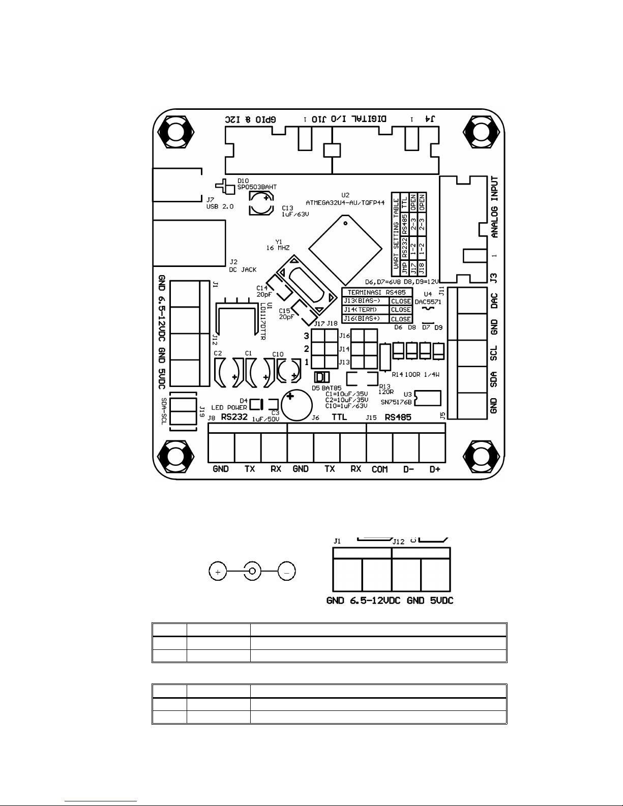
J2 DC Jack and J1 blue terminal are connectors for power supply input, whilst
J12 blue terminal functions as voltage output from regulator.
J1
Pin Name Function
1 GND Ground reference for power supply input
2 6.5-12VDC Connected to power supply input (6.5-12 volt)
J12
Pin Name Function
1 GND Ground reference for power supply output
2 5VDC Voltage output from regulator (±5.1 Volt)
4
Page 5
SDA SCL
SDA SCL
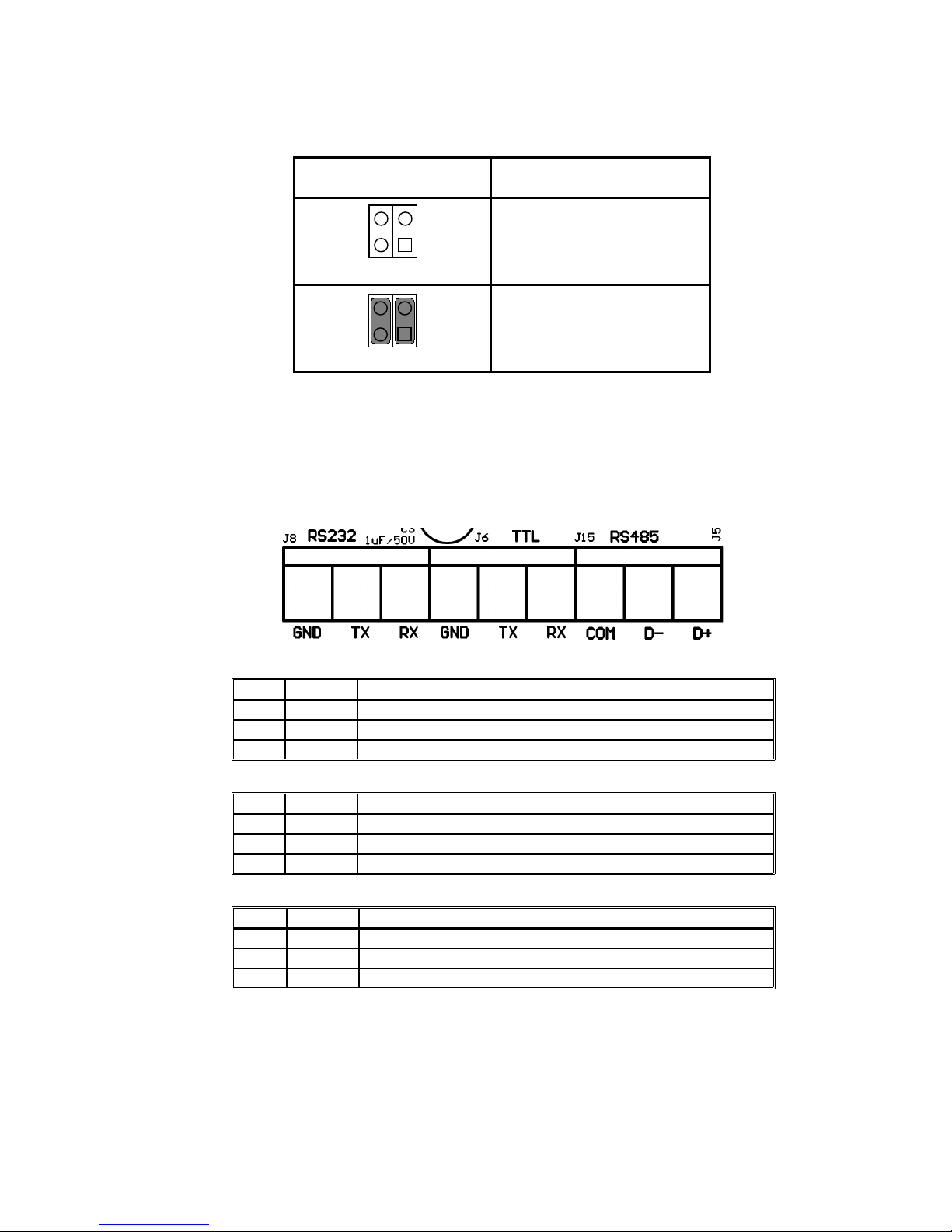
SDA-SCL (J19) jumpers are used to activate the pull up resistors for SDA and
SCL pins of the I2C interface.
SDA-SCL jumper
J19
Function
Pull-up inactive
(jumper released)
Pull-up active
(jumper attached)
Important !
If more than one module are connected to I2C-bus, then only the SDA-SCL
jumpers of one of the modules need to be attached.
RS232 (J8) blue terminal is a connector for RS232 UART interface, TTL (J6)
blue terminal is a connector for TTL UART interface, while RS485 (J15) blue
terminal is a connector for RS485 UART interface.
J8 (RS232)
Pin Name Function
1 GND Ground reference
2 TX UART (RS232) output line from the module
3 RX UART (RS232) input line to the module
J6 (TTL)
Pin Name Function
1 GND Ground reference
2 TX UART (TTL) output line from the module
3 RX UART (TTL) input line to the module
J15
Pin Name Function
1 GND Ground reference
2 D- Data line (inverting –)
3 D+ Data line (non-inverting +)
5
Page 6
J17 J18
3
2
1
16
14
13
16
14
13
16
14
13
J17 J18
3
2
1
J17 J18
3
2
1
16
14
13
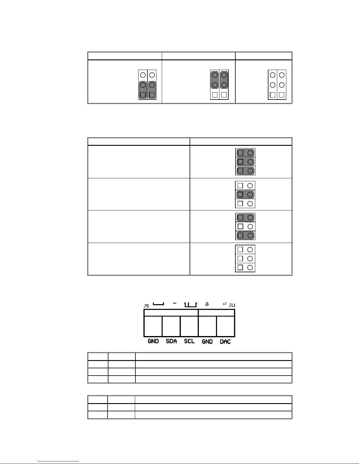
J17 and J18 jumpers are used to select UART communication line.
UART RS232 UART RS485 UART TTL
Jumper on
position 1 – 2
Jumper on
position 2 – 3
Jumper
released
J13, J14, and J16 jumpers are used as bias-, termination, and bias +. Usually,
in one RS485 line, there's only 1 pair of bias - and bias +, while terminations
are only placed in the outermost modules.
Condition Examples Jumper Configuration Examples
If module is at the end of line and
the network doesn't have bias +/–
If module is at the end of line and
there is bias +/- on the network
If module is not at the end of line
and the network doesn't have bias
+/-
If module is not at the end of line
and there is bias +/- on the network
J5 blue terminal is a connector for I2C interface, while J11 blue terminal is a
connector for DAC.
J5
Pin Name Function
1 GND Ground reference
2 SDA I2C-bus input/output data
3 SCL I2C-bus clock input
J11
Pin Name Function
1 GND Ground reference
2 DAC Voltage output from DAC
6
Page 7
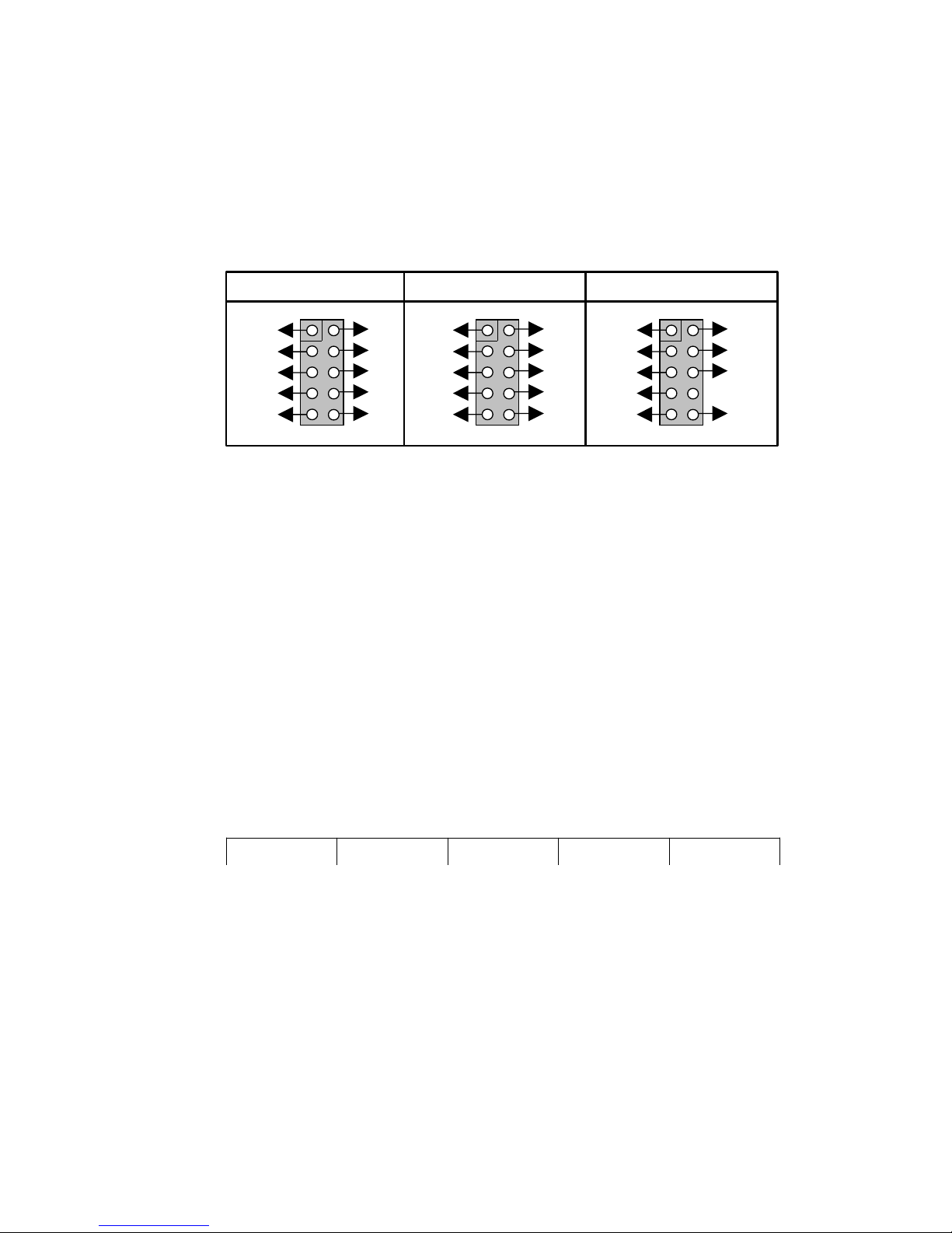
ANALOG INPUT (J3) header consists of pins that can be used as analog inputs
or digital inputs/outputs. A7 pin can also be used as Counter 1.
DIGITAL I/O (J4) header consists of pins that can be used as digital
inputs/outputs. DIO7 pin can also be used as Counter 0.
GPIO & I2C (J10) header consists of pins that can be used as digital
inputs/outputs as well as SDA and SCL pins for I2C.
Specification and characteristics of each pin can be seen in the datasheet.
3. INTERFACE
PC-LINK USB SMART I/O has a USB interface that will be recognized and
accessible by computer as UART COM port (virtual).
3.1. UART Interface
UART communication parameters are as follows:
• 110 – 256000 bps
• 8 data bit
• 1 stop bit
• no parity bit
• no flow control
Each data packet sent by host begins with initial byte that is followed with 1
byte sum of command byte+data, 1 byte command code, n byte parameter (if
needed) and ends with 1 byte LRC.
Start Byte Byte Count Command Parameter LRC
Start Byte always have 0x58 ($58) hexadecimal or 88 decimal value.
Byte Count is the sum of Command and Parameter byte (excluding Start Byte,
Byte Count, and LRC).
LRC is an error checking byte by summing all bytes, from Start Byte to the last
Parameter. Only LSB will be taken from the sum results and two's complement
will be performed.
PC-LINK USB SMART I/O has a timeout feature for packet reception from host.
If there is no received data in ± 1 second, the next data will be treated as a
new data packet and module will wait for Start Byte.
If timeout occurs in the middle of the packet, then the packet will be ignored.
For commands that ask for data, the format of replied data packet from the
module will be the same as the format of data packet from the host.
7
AGND
A0
A2
A4
A6
VCC
A1
A3
A5
A7
2
1
1
0
9
ANALOG INPUT (J3) DIGITAL I/O (J4)
PGND
DIO0
DIO2
DIO4
DIO6
VCC
DIO1
DIO3
DIO5
DIO7
2
1
1
0
9
PGND
GPIO0
GPIO2
GPIO4
SDA
VCC
GPIO1
GPIO3
SCL
2
1
1
0
9
GPIO & I2C (J10)
Page 8
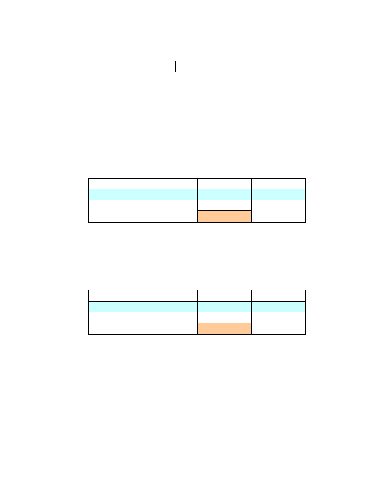
For commands that do not ask for data, the module will respond with ACK
(0xAA) or NACK (0xEE).
Start Byte 0x01 0xAA / 0xEE LRC
Available commands and parameters can be seen on section 3.2.
Default settings on purchase:
– ANALOG INPUT functions as analog input (no internal pull-up resistor).
– DIGITAL I/O and GPIO functions as digital input (no internal pull-up
resistor, Counters are inactive).
– Baud rate UART 9600 bps.
– Bit rate I
2
C 50 kHz.
3.2. COMMAND SET
3.2.1. PING
Is used to check whether the communication line to the module still exists.
Byte Count Command Parameter
Host Command 1 0xFF -
Module Response 1
0xAA
-
0xEE
If packet is recognized and correct, module will respond with ACK (0xAA).
If the packet is false/not recognized, module will respond with NACK (0xEE).
Example:
PC : 0x58 0x01 0xFF 0xA8
USB Smart I/O : 0x58 0x01 0xAA 0xFD
3.2.2. RESET
Is used to perform soft-reset on the module.
Byte Count Command Parameter
Host Command 1 0x01 -
Module Response 1
0xAA
-
0xEE
If packet is recognized and correct, module will respond with ACK (0xAA).
Module will perform soft-reset with the following effects:
– Module's USB function will be turned off so it will be disconnected from the
computer.
– Module will repeat the process from the start, including USB connection
initialization and EEPROM reading to get each I/O function setting data.
– DAC output is unchanged.
If the packet is false/not recognized, module will respond with NACK (0xEE).
Example:
PC : 0x58 0x01 0x01 0xA6
USB Smart I/O : 0x58 0x01 0xAA 0xFD
8
Page 9
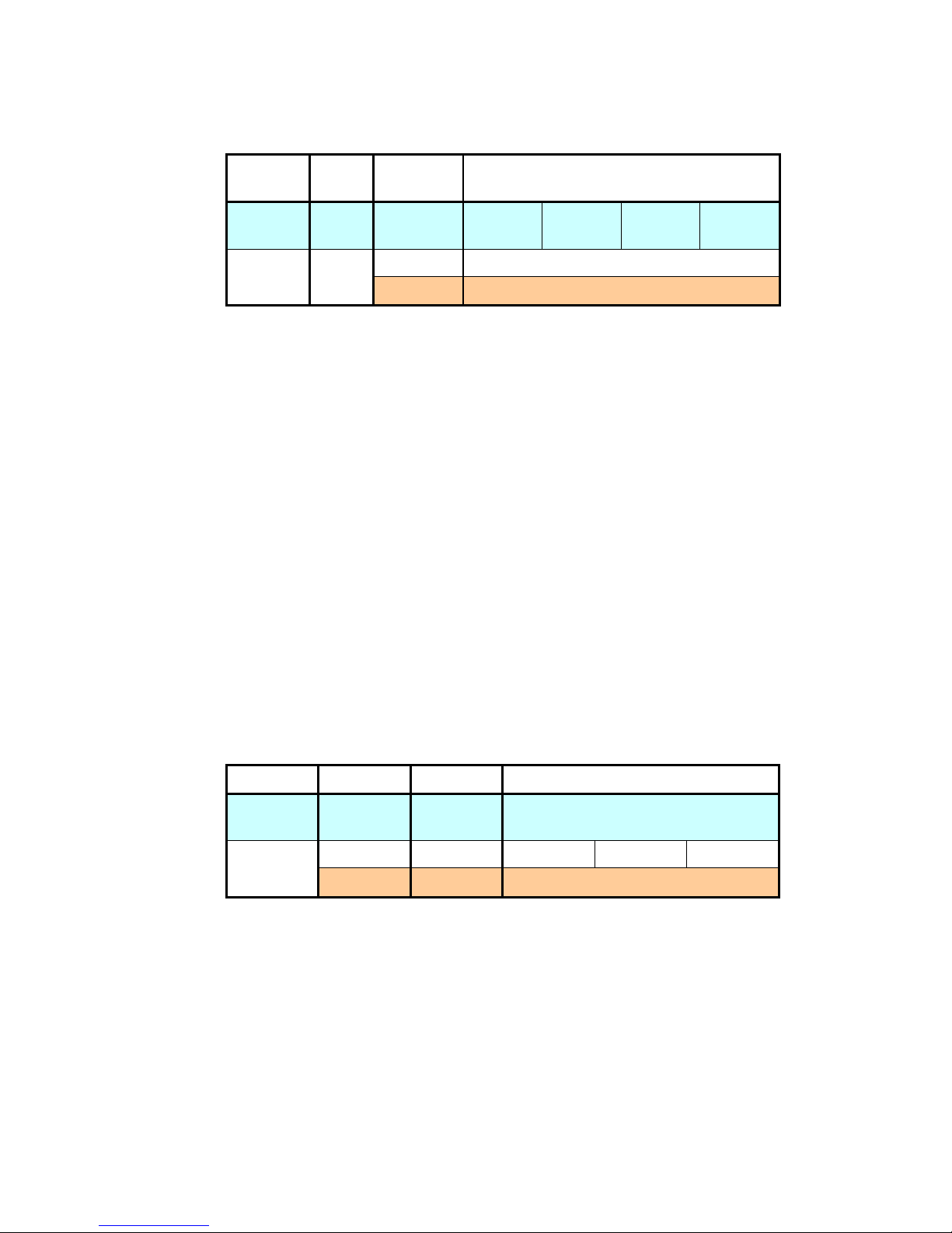
3.2.3. SET FUNCTION
Is used to set the I/O function on the module.
Byte
Count
Command Parameter
Host
Command
5 0x10 PORT ANALOG DIRECT PULL-UP
Module
Response
1
0xAA -
0xEE -
PORT parameter is the port code that will be accessed. 0 represents Analog
Input, 1 represents Digital I/O, and 2 represents General Purpose I/O.
ANALOG parameter represents 8 bits in 1 port. Each bit is cleared (0) when
used as digital i/o or set (1) when used as analog input. When the bit is set (1),
then DIRECT and PULL-UP parameters for that bit will be ignored. This
parameter only applies for PORT 0.
DIRECT parameter represents 8 bits (or 5 bits on General Purpose I/O) in 1
port. Each bit is cleared (0) when used as input or set (1) when used as output.
PULL-UP parameter represents 8 bits (or 5 bits on General Purpose I/O) in 1
port. Each bit is cleared (0) to put the represented pin on three-state/low
condition, or set (1) to activate its internal pull up resistor.
This setting will be saved in EEPROM so it will not be erased when module is
powered off.
If packet is recognized and correct, module will respond with ACK (0xAA).
If the packet is false/not recognized, module will respond with NACK (0xEE).
Example:
PC : 0x58 0x05 0x10 0x01 0x00 0xF0 0x0F 0x93
USB Smart I/O : 0x58 0x01 0xAA 0xFD
will use Digital I/O bit 4-7 as output lines with 0 values, while bit 0-3 as input
lines with active internal pull up resistors.
3.2.4. GET FUNCTION
Is used to read I/O function settings on the module.
Byte Count Command Parameter
Host
Command
2 0x11 PORT
Module
Response
4 0x11 ANALOG DIRECT PULL-UP
1 0xEE -
PORT parameter is the port code that will be accessed. 0 represents Analog
Input, 1 represents Digital I/O, and 2 represents General Purpose I/O.
ANALOG parameter represents 8 bits in 1 port. Each bit is cleared (0) when
used as digital i/o or set (1) when used as analog input. When the bit is set (1),
then DIRECT and PULL-UP parameters for that bit must be ignored. This
parameter only applies for PORT 0.
DIRECT parameter represents 8 bits (or 5 bits on General Purpose I/O) in 1
port. Each bit is cleared (0) when used as input or set (1) when used as output.
PULL-UP parameter represents 8 bits (or 5 bits on General Purpose I/O) in 1
port. Each bit is cleared (0) if the represented pin is on three-state/low
condition, or set (1) if the internal pull up resistor on the pin is active.
If packet is recognized and correct, module will respond with EEPROM reading
data result.
9
Page 10
If the packet is false/not recognized, module will respond with NACK (0xEE).
Example:
PC : 0x58 0x02 0x11 0x02 0x93
USB Smart I/O : 0x58 0x04 0x11 0x00 0x00 0x1F 0x74
means that the computer requests for General Purpose I/O function and
module replies that all General Purpose I/O are digital inputs with active
internal pull-up resistors.
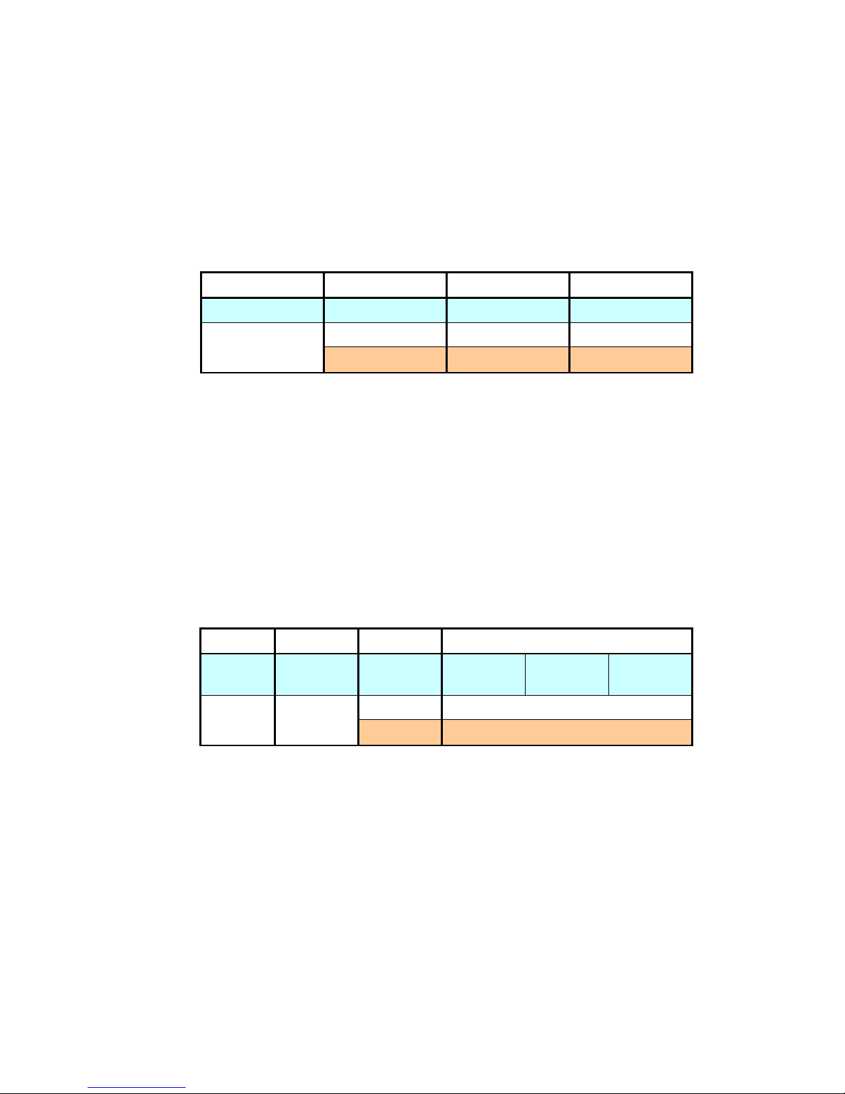
3.2.5. GET PORT
Is used to command the module to read the value of a certain port.
Byte Count Command Parameter
Host Command 2 0x12 PORT
Module Response
2 0x12 BYTEVALUE
1 0xEE -
PORT parameter is the port code that will be accessed. 0 represents Analog
Input, 1 represents Digital I/O, and 2 represents General Purpose I/O.
BYTEVALUE parameter is the value of the port (register PORTx).
If packet is recognized and correct, module will respond with data reading
result.
If the packet is false/not recognized, module will respond with NACK (0xEE).
Example:
PC : 0x58 0x02 0x12 0x01 0x93
USB Smart I/O : 0x58 0x02 0x12 0x88 0x0C
means that the computer requests the value to Digital I/O and module replies
that the PORT value on that port is 0x88.
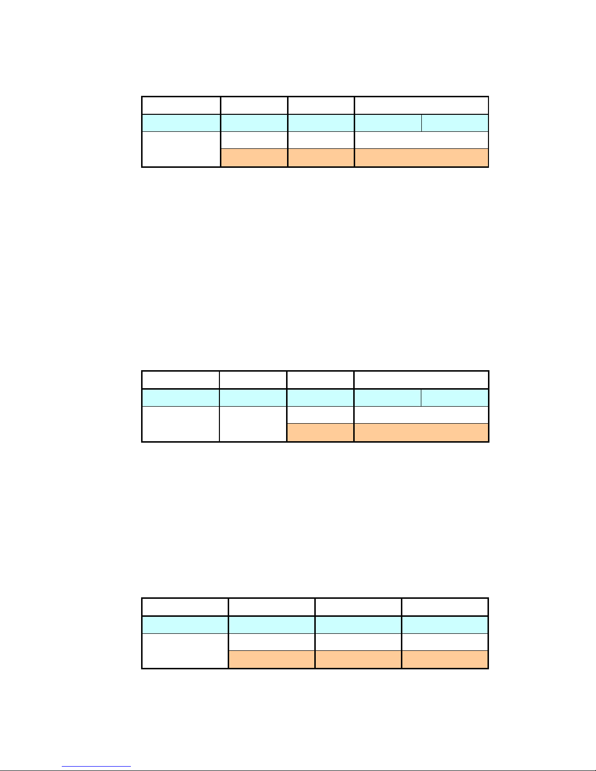
3.2.6. SET BIT
Is used to command the module to change the value of 1 pin on a certain port.
Byte Count Command Parameter
Host
Command
4 0x13 PORT BIT BITVALUE
Module
Response
1
0xAA -
0xEE -
PORT parameter is the port code that will be accessed. 0 represents Analog
Input, 1 represents Digital I/O, and 2 represents General Purpose I/O.
BIT parameter are the bit numbers (0-7) that will be accessed.
BIT parameter VALUE are the values that will be sent to the bits. It is cleared
(0) to send low logic or set (1) to send high logic.
If packet is recognized and correct, module will respond with ACK (0xAA).
If the packet is false/not recognized, module will respond with NACK (0xEE).
Example:
PC : 0x58 0x04 0x13 0x01 0x05 0x01 0x8A
USB Smart I/O : 0x58 0x01 0xAA 0xFD
will send a value of 1/high to Digital I/O bit 5.
10
Page 11
3.2.7. GET BIT
Is used to command the module to read the value of 1 pin on a certain port.
Byte Count Command Parameter
Host Command 3 0x14 PORT BIT
Module
Response
2 0x14 BITVALUE
1 0xEE -
PORT parameter is the port code that will be accessed. 0 represents Analog
Input, 1 represents Digital I/O, and 2 represents General Purpose I/O.
BIT parameter are the bit numbers (0-7) that will be accessed.
BIT parameter VALUE are the the value of the bit (register PINx), cleared (0)
for low logic or set (1) for high logic.
If packet is recognized and correct, module will respond with data reading
result.
If the packet is false/not recognized, module will respond with NACK (0xEE).
Example:
PC : 0x58 0x03 0x14 0x00 0x02 0x8F
USB Smart I/O : 0x58 0x02 0x14 0x00 0x92
means that the computer requests the value of bit 2 on Analog Input and
module replies that the logic on that bit is low.
3.2.8. SET BYTE
Is used to command the module to change the value of a certain port.
Byte Count Command Parameter
Host Command 3 0x15 PORT BYTEVALUE
Module
Response
1
0xAA -
0xEE -
PORT parameter is the port code that will be accessed. 0 represents Analog
Input, 1 represents Digital I/O, and 2 represents General Purpose I/O.
BYTEVALUE parameter is the the value of the byte that will be sent to the port.
If packet is recognized and correct, module will respond with ACK (0xAA).
If the packet is false/not recognized, module will respond with NACK (0xEE).
Example:
PC : 0x58 0x03 0x15 0x00 0x55 0x3B
USB Smart I/O : 0x58 0x01 0xAA 0xFD
will send a value of 0x55 to Analog Input.
3.2.9. GET BYTE
Is used to command the module to read the value of a certain port.
Byte Count Command Parameter
Host Command 2 0x16 PORT
Module Response
2 0x16 BYTEVALUE
1 0xEE -
PORT parameter is the port code that will be accessed. 0 represents Analog
Input, 1 represents Digital I/O, and 2 represents General Purpose I/O.
BYTEVALUE parameter is the value of the port (register PINx).
11
Page 12
If packet is recognized and correct, module will respond with data reading
result.
If the packet is false/not recognized, module will respond with NACK (0xEE).
Example:
PC : 0x58 0x02 0x16 0x01 0x8F
USB Smart I/O : 0x58 0x02 0x16 0x88 0x08
means that the computer requests the value of Digital I/O and module replies
that the PIN value of that port is 0x88.
3.2.10.GET ADC
Is used to command the module to read ADC value of a certain channel.
Byte Count Command Parameter
Host Command 2 0x17 CHANNEL
Module
Response
3 0x17 MSB LSB
1 0xEE -
CHANNEL parameter is the ADC channels (0-7) that will be read.
MSB parameter is the most significant byte of ADC reading result.
LSB parameter is the least significant byte of ADC reading result.
If packet is recognized and correct, module will respond with data reading
result.
If the packet is false/not recognized, module will respond with NACK (0xEE).
Example:
PC : 0x58 0x02 0x17 0x03 0x8C
USB Smart I/O : 0x58 0x03 0x17 0x03 0xFF 0x8C
means that the computer requests the value of ADC channel 3 and module
replies that the ADC value of that channel is 1023 (0x03FF).
3.2.11.SET BIT RATE
Is used to set the I2C bit rate.
Byte Count Command Parameter
Host Command 3 0x20 BITRATEH BITRATEL
Module
Response
1
0xAA
-
0xEE
RATEH parameter BIT is the most significant byte of BITRATE.
RATEL parameter BIT is the least significant byte of BITRATE.
BITRATE parameter is the bit rate value in kHz. The allowed BITRATE value are
around 30-400.
This setting will be saved on EEPROM so it will not be erased when module is
powered off.
If packet is recognized and correct, module will respond with ACK (0xAA).
If the packet is false/not recognized, module will respond with NACK (0xEE).
Example:
PC : 0x58 0x03 0x20 0x00 0x64 0x21
USB Smart I/O : 0x58 0x01 0xAA 0xFD
sets the bit rate for I2C to 100 (0x0064) kHz.
12
Page 13
3.2.12.GET BIT RATE
Is used to read bit rate I2C.
Byte Count Command Parameter
Host Command 1 0x21 -
Module
Response
3 0x21 BITRATEH BITRATEL
1 0xEE -
RATEH parameter BIT is the most significant byte of BITRATE.
RATEL parameter BIT is the least significant byte of BITRATE.
BITRATE parameter is the bit rate value in kHz.
If packet is recognized and correct, module will respond with bit rate value.
If the packet is false/not recognized, module will respond with NACK (0xEE).
Example:
PC : 0x58 0x01 0x21 0x86
USB Smart I/O : 0x58 0x03 0x21 0x00 0x32 0x52
means that the computer requests bit rate value and module replies that the bit
rate value is 50 (0x0032) kHz.
3.2.13.I2C START
Is used to command the module to send the start condition to I2C line.
Byte Count Command Parameter
Host Command 1 0x22 -
Module Response 1
0xAA
-
0xEE
If packet is recognized and correct, module will respond with ACK (0xAA).
If the packet is false/not recognized, module will respond with NACK (0xEE).
Example:
PC : 0x58 0x01 0x22 0x85
USB Smart I/O : 0x58 0x01 0xAA 0xFD
3.2.14.I2C WRITE
Is used to command the module to send 1 byte via I2C line.
Byte Count Command Parameter
Host Command 2 0x23 1 byte data
Module Response 1
0xAA
-
0xEE
If packet is recognized and correct, module will respond with ACK (0xAA).
If the packet is false/not recognized, module will respond with NACK (0xEE).
Example:
PC : 0x58 0x02 0x23 0xA0 0xE3
USB Smart I/O : 0x58 0x01 0xAA 0xFD
sends a value of 160 (0xA0) via I2C.
13
Page 14
3.2.15.I2C READ
Is used to command the module to read 1 byte via I2C line.
Byte Count Command Parameter
Host Command 2 0x24
0x00 (nack)
0x01 (ack)
Module Response
2 0x24 1 byte data
1 0xEE -
Parameter of host is given value of 0 to respond the I2C reception with not
acknowledge and value of 1 to respond I2C reception with acknowledge.
If packet is recognized and correct, module will respond with data reading
result.
If the packet is false/not recognized, module will respond with NACK (0xEE).
Example:
PC : 0x58 0x02 0x24 0x00 0x82
USB Smart I/O : 0x58 0x02 0x24 0x90 0xF2
means that the computer requests 1 data that is found on I2C line and will be
responded with not acknowledge. Module replies that the data reading result
via I2C has a value of 144 (0x90).
3.2.16.I2C STOP
Is used to command the module to send stop condition to I2C line.
Byte Count Command Parameter
Host Command 1 0x25 -
Module Response 1
0xAA
-
0xEE
If packet is recognized and correct, module will respond with ACK (0xAA).
If the packet is false/not recognized, module will respond with NACK (0xEE).
Example:
PC : 0x58 0x01 0x25 0x82
USB Smart I/O : 0x58 0x01 0xAA 0xFD
3.2.17.I2C SEND PACKET
Is used to command the module to sends 1 data packet via I2C line.
Byte Count Command Parameter
Host Command 2 – 36 0x26 1 – 35 byte
Module Response 1
0xAA
-
0xEE
Parameter with maximum amount of 35 bytes includes I2C device address.
Transmission will be performed consecutively.
Module will send start condition, parameters on command, and stop condition.
If packet is recognized and correct, module will respond with ACK (0xAA).
If the packet is false/not recognized, module will respond with NACK (0xEE).
Example:
PC : 0x58 0x05 0x26 0xD0 0x01 0x02 0x03 0xA7
USB Smart I/O : 0x58 0x01 0xAA 0xFD
14
Page 15
will send start condition, 0xD0 (I2C device write address that will be accessed),
0x01, 0x02, 0x03, and stop condition.
3.2.18.I2C GET PACKET
Is used to command the module to read 1 data packet via I2C line.
Byte Count Command Parameter
Host Command 3 0x27 ADDR COUNT
Module
Response
2 – 33 0x27 1 – 32 byte
1 0xEE -
ADDR parameter is the I2C device address that will be accessed.
COUNT parameter is the amount of data that will be read.
This command will only perform the reading process. To choose the data
address that will be read (for example, accessing EEPROM), data address can
be determined previously using the I2CSENDPACKET.
Module will send start condition, I2C device read address (ADDR|0x01), read
data as many as COUNT, and send stop condition.
If packet is recognized and correct, module will respond with data reading
results (maximum of 32 bytes).
If the packet is false/not recognized, module will respond with NACK (0xEE).
Example:
PC : 0x58 0x03 0x27 0xD0 0x01 0xAD
USB Smart I/O : 0x58 0x02 0x27 0x03 0x7C
means that the computer commands the module to read 1 byte of I2C device
with 0xD1 address. Module replies that the reading results via I2C is 0x03.
3.2.19.SET BAUD RATE
Is used to set UART baud rate.
Byte Count Command Parameter
Host Command 2 0x30 BAUDRATE
Module Response 1
0xAA
-
0xEE
BAUDRATE parameter is the baud rate value code.
Code 1 = baud rate 9600 bps
Code 2 = baud rate 19200 bps
Code 3 = baud rate 38400 bps
Code 4 = baud rate 57600 bps
This setting will be saved in EEPROM so it will not be erased when module is
powered off.
If packet is recognized and correct, module will respond with ACK (0xAA).
If the packet is false/not recognized, module will respond with NACK (0xEE).
Example:
PC : 0x58 0x02 0x30 0x03 0x73
USB Smart I/O : 0x58 0x01 0xAA 0xFD
will set baud rate to 38400 bps.
15
Page 16
3.2.20.GET BAUD RATE
Is used to read UART baud rate.
Byte Count Command Parameter
Host Command 1 0x31 -
Module Response
2 0x31 BAUDRATE
1 0xEE -
BAUDRATE parameter is the baud rate value code.
If packet is recognized and correct, module will respond with baud rate value
code.
If the packet is false/not recognized, module will respond with NACK (0xEE).
Example:
PC : 0x58 0x01 0x31 0x76
USB Smart I/O : 0x58 0x02 0x31 0x03 0x72
means that the computer requests for baud rate value and module replies that
the baud rate has a value of 38400 bps.
3.2.21.SEND UART
Is used to command the module to send a series of data via UART line.
Byte Count Command Parameter
Host Command 2 – 33 0x32 1 – 32 byte
Module Response 1
0xAA
-
0xEE
Up to 32 bytes parameter will be transmitted consecutively.
If packet is recognized and correct, module will respond with ACK (0xAA).
If the packet is false/not recognized, module will respond with NACK (0xEE).
Example:
PC : 0x58 0x04 0x32 0x01 0x02 0x03 0x6C
USB Smart I/O : 0x58 0x01 0xAA 0xFD
will send 0x01, 0x02, and 0x03 data via UART line.
3.2.22.GET UART
Is used to command the module to read a series of data via UART line.
Byte Count Command Parameter
Host Command 2 0x33 COUNT
Module Response
2 – 33 0xA3 1 – 32 byte
1
0xAA
-
0xEE
COUNT parameter is the amount of data that will be read.
If packet is recognized and correct, module will respond with data reading
results. These are the received data (maximum 32 bytes).
If the received data is more than 32 bytes, then the 33rd data onwards will
overwrite the first data and onwards (roll-over).
If the COUNT value is larger than the amount of data on the buffer, then the
module will only send the data on the buffer.
16
Page 17
If the COUNT value is smaller than the amount of data on the buffer, then the
module will only send data as many as COUNT value.
After reading process, all of buffer contents will be erased.
If there is no data reception, module will respond with ACK (0xAA).
If the packet is false/not recognized, module will respond with NACK (0xEE).
Example:
PC : 0x58 0x02 0x33 0x03 0x70
USB Smart I/O : 0x58 0x04 0x33 0x01 0x02 0x03 0x6B
means that the computer requests for 3 data and module replies with reading
results, which are 0x01, 0x02, 0x03.
3.2.23.SEND DAC
Is used to command the module to send value to DAC and convert it into analog
voltage.
Byte Count Command Parameter
Host Command 2 0x40 VALUE
Module Response 1
0xAA
-
0xEE
Parameter VALUE are the values (0-255) that will be converted into analog
voltage (0-±5.1).
If packet is recognized and correct, module will respond with ACK (0xAA).
If the packet is false/not recognized, module will respond with NACK (0xEE).
Example:
PC : 0x58 0x02 0x40 0x80 0xE6
USB Smart I/O : 0x58 0x01 0xAA 0xFD
will send a value of 128 (0x80) to DAC that will be converted to about 2.58 V
voltage.
3.2.24.STOP COUNTER
Is used to command the module to stop a certain counter.
Byte Count Command Parameter
Host Command 2 0x50 COUNTER
Module Response 1
0xAA
-
0xEE
COUNTER parameter is the counter number that will be accessed, has a value
of 0 or 1.
If packet is recognized and correct, module will respond with ACK (0xAA).
If the packet is false/not recognized, module will respond with NACK (0xEE).
Example:
PC : 0x58 0x02 0x50 0x01 0x55
USB Smart I/O : 0x58 0x01 0xAA 0xFD
will stop Counter 1.
17
Page 18
3.2.25.START COUNTER
Is used to command the module to activate a certain counter.
Byte Count Command Parameter
Host Command 2 0x51 COUNTER
Module Response 1
0xAA
-
0xEE
COUNTER parameter is the counter number that will be accessed, has a value
of 0 or 1.
When the counter is activated with this command, then the pin that the counter
used will be configured into a digital input with active internal pull-up resistor.
This new setting will also be saved into EEPROM.
If packet is recognized and correct, module will respond with ACK (0xAA).
If the packet is false/not recognized, module will respond with NACK (0xEE).
Example:
PC : 0x58 0x02 0x51 0x00 0x55
USB Smart I/O : 0x58 0x01 0xAA 0xFD
will activate Counter 0.
3.2.26.GET COUNTER
Is used to command the module to read counting results of a certain counter.
Byte Count Command Parameter
Host Command 2 0x52 COUNTER
Module
Response
3 0x52 MSB LSB
1 0xEE -
COUNTER parameter is the counter number that will be accessed, has a value
of 0 or 1.
MSB parameter is the most significant byte of counter reading results.
LSB parameter is the least significant byte of counter reading results.
If packet is recognized and correct, module will respond with data reading
results.
If the packet is false/not recognized, module will respond with NACK (0xEE).
Example:
PC : 0x58 0x02 0x52 0x00 0x54
USB Smart I/O : 0x58 0x03 0x52 0x01 0x80 0xD2
means that the computer requests the value of Counter 0 and module replies
that the counter value is 384 (0x0180).
3.2.27.GET VERSION
Is used to read module firmware version.
Byte Count Command Parameter
Host Command 1 0xFE -
Module
Response
3 0xFE Major Minor
1 0xEE -
Parameter Major and Minor show the firmware version in decimals with
Major.Minor format.
18
Page 19
If packet is recognized and correct, module will respond with data reading
results.
If the packet is false/not recognized, module will respond with NACK (0xEE).
Example:
PC : 0x58 0x01 0xFE 0xA9
USB Smart I/O : 0x58 0x03 0xFE 0x01 0x00 0xA6
means that the computer requests the firmware version and module replies
that the version is 1.0 (0x01 0x00).
4. Testing Procedure
1. Connect DT-I/O I2C Peripheral to PC-LINK USB SMART I/O via J5 blue
terminal.
2. Connect DT-I/O RS232-RS485 Converter, DT-I/O Neo RS232 to RS485
Converter, or DT-I/O USB to UART Converter to computer and to PC-LINK
USB SMART I/O via RS485 (J15) blue terminal.
3. Prepare a Voltmeter and DT-I/O LED Logic Tester.
4. Connect power supply to the modules.
5. If the power supply has been correctly connected, then the POWER PCLINK USB SMART I/O will light up.
6. Connect the USB Mini-B connector to USB port on the computer using the
provided USB cable.
7. Run SmartIO.exe.
8. Select the COM Port that will be used. Click the Refresh button to show the
recently connected COM port.
9. Click Open.
10.On the Testing section (right), give the check mark on the Auto, then Click
the Test button.
11.Follow each step that appear before and after testing procedures.
12.ANALOG INPUT, DIGITAL I/O, and GP I/O testing will make DT-I/O LED
Logic Tester's LEDs blink alternately.
13.DAC testing will produce increasing voltage of 0 up to ±5.1VDC.
14.I2C testing will write and read DT-I/O I2C Peripheral's EEPROM. The
results of writing and reading of the first 8 bytes must have the same
results, which are 1, 3, 7, 15, 31, 63, 127, and 255.
19
Page 20
15.UART TTL and RS232 (by shorting RX and TX) will produce the same byte
values between Out and In, which are 1, 3, 7, 15, 31, 63, 127, and 255.
When the connection between RX and TX is released, the status bar (in the
bottom) will show that there is no data.
16.UART RS485 testing will send 1, 3, 7, 15, 31, 63, 127, and 255 to
computer. And the next data sent by the computer must match the data that
the module reads.
5. PROGRAM EXAMPLE
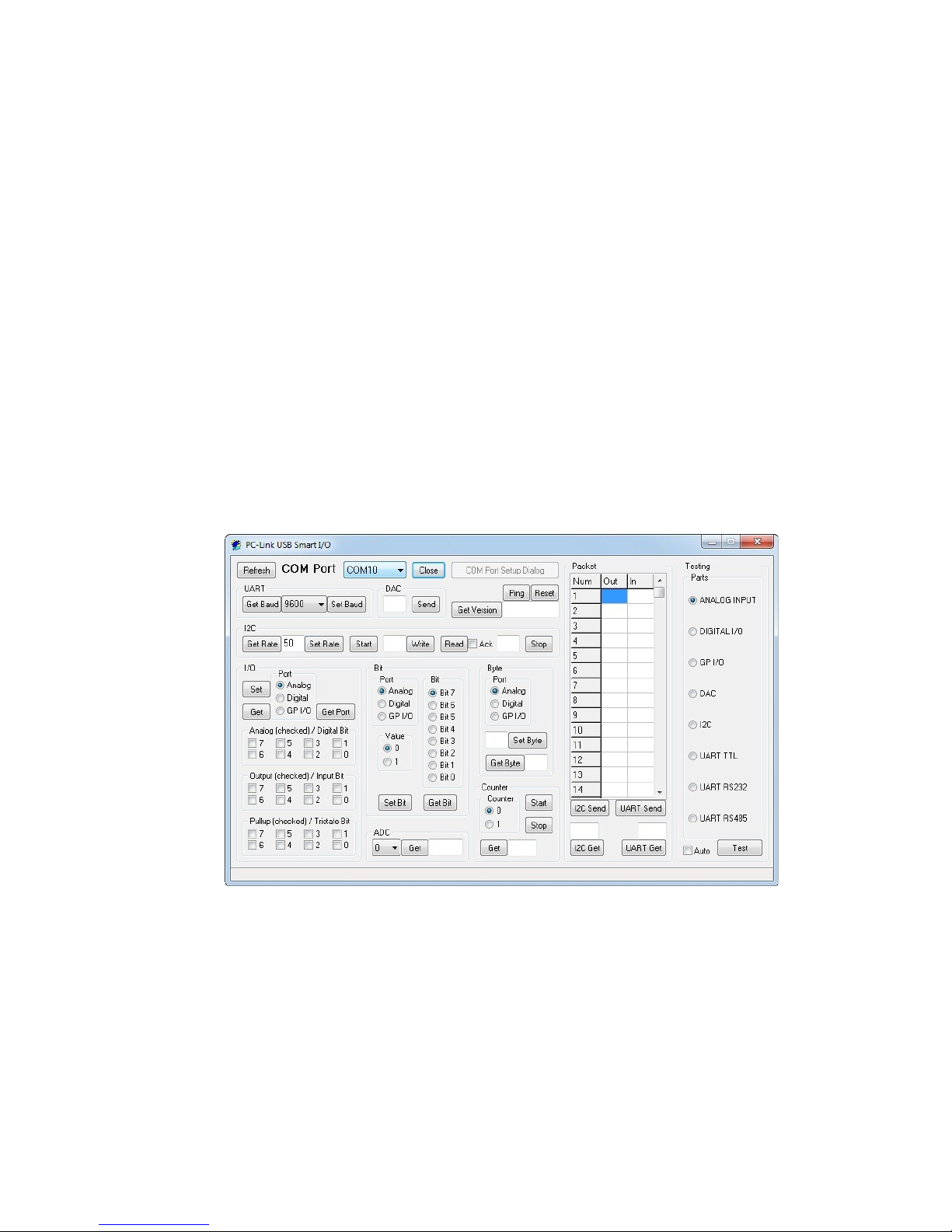
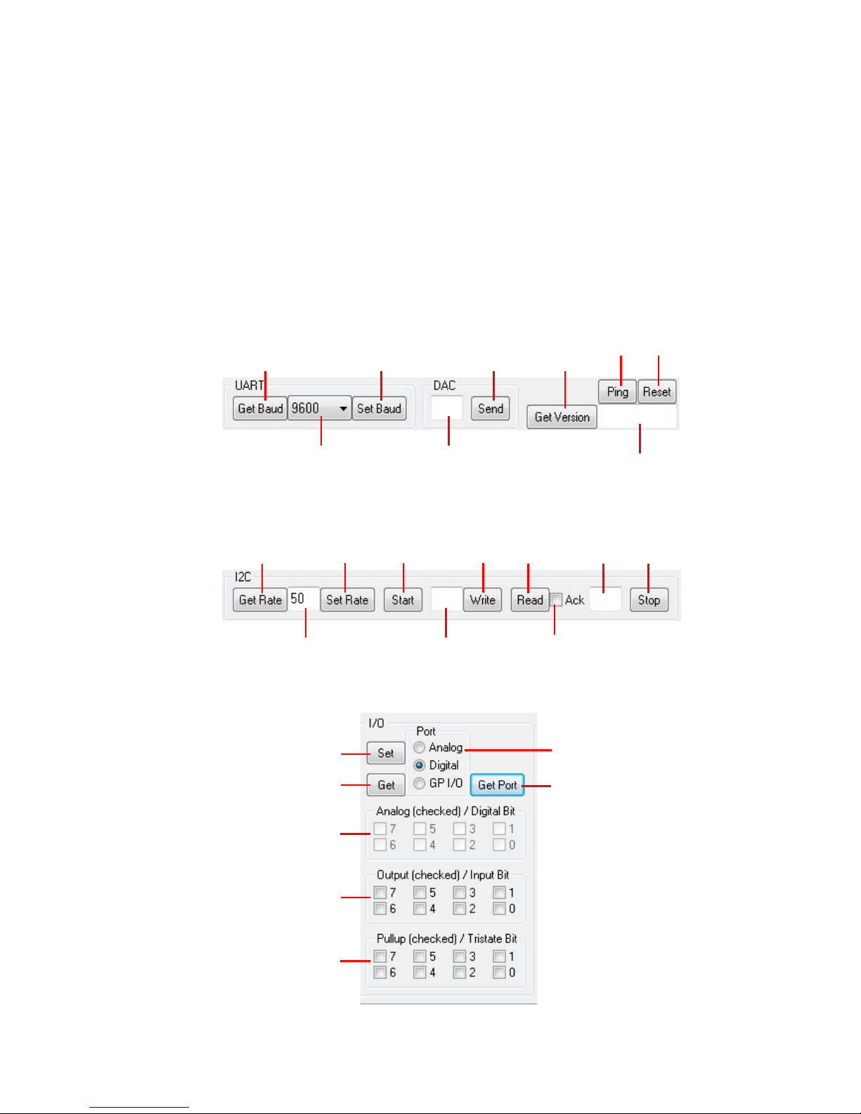
SmartIO program source code is included in the CD/DVD. This source code can
be used as a guideline to make other programs.
The following are the explanations of each SmartIO.exe GUI function.
20
Get Baud
Rate
Set Baud
Rate
Baud Rate reading results /
Determined Baud Rate
Send DAC
Value sent
to DAC
Get Version
Ping Reset
Version reading
result
Get Bit
Rate
Set Bit
Rate
Bit Rate reading results /
Determined Bit Rate
I2C
Start
Sent byte
I2C
Write
I2C
Read
I2C
Stop
Reading
result byte
Ack/Nack
Get Function
Get Port
Analog
Direct
Pull-up
Port Selection
Set Function
Page 21
21
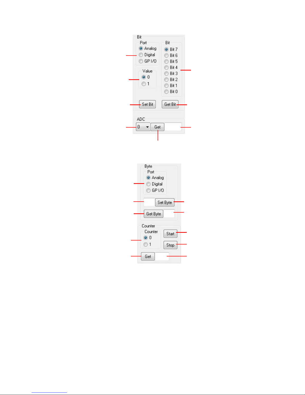
Logika Bit
Bit Selection
Set Bit Get Bit
ADC Channel Selection
Port Selection
ADC reading results
Get ADC
Sent Byte Set Byte
Get Byte
Reading result bytes
Get Counter
Port Selection
Counter reading results
Counter selection
Start Counter
Stop Counter
Page 22
♦ Thank you for your confidence in using our products, if there are difficulties, questions,
or suggestions regarding this product please contact our technical support:
22
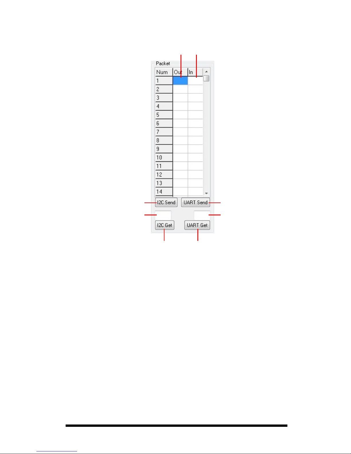
I2C Send Packet Send UART
Amount of I2C bytes
that will be read
Amount of UART bytes
that will be read
I2C Get
Packet
Get UART
Sent data
column
Read data
column
Page 23
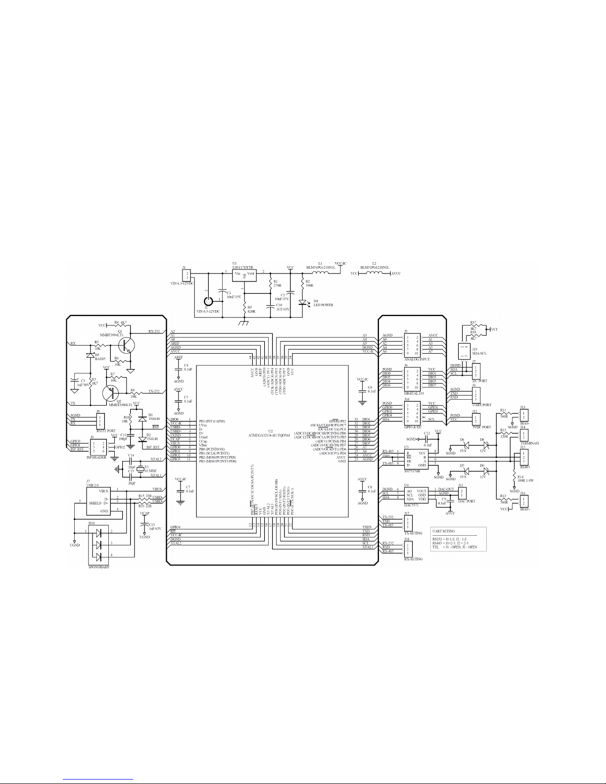
Attachment A.
PC-LINK USB SMART I/O Schematics
23
 Loading...