

Philips PBSS5350S Technical data
查询PBSS5350S供应商
DISCRETE SEMICONDUCTORS
DATA SH EET
lfpage
M3D186
PBSS5350S
50 V low V
Product specification 2001 Nov 19
CEsat
PNP transistor

Philips Semiconductors Product specification
50 V low V
CEsat
PNP transistor
FEATURES
• High power dissipation (830 mW)
• Ultra low collector-emitter saturation voltage
• 3 A continuous current
• High current switching
• Improved device reliability due to reduced heat
generation
APPLICATIONS
• Medium power switching and muting
• Linear regulators
• DC/DC convertor
• Supply line switching circuits
• Battery management applications
• Strobe flash units
• Heavydutybatterypoweredequipment(motorandlamp
drivers).
DESCRIPTION
PBSS5350S
QUICK REFERENCE DATA
SYMBOL PARAMETER MAX. UNIT
V
CEO
I
C
I
CM
R
CEsat
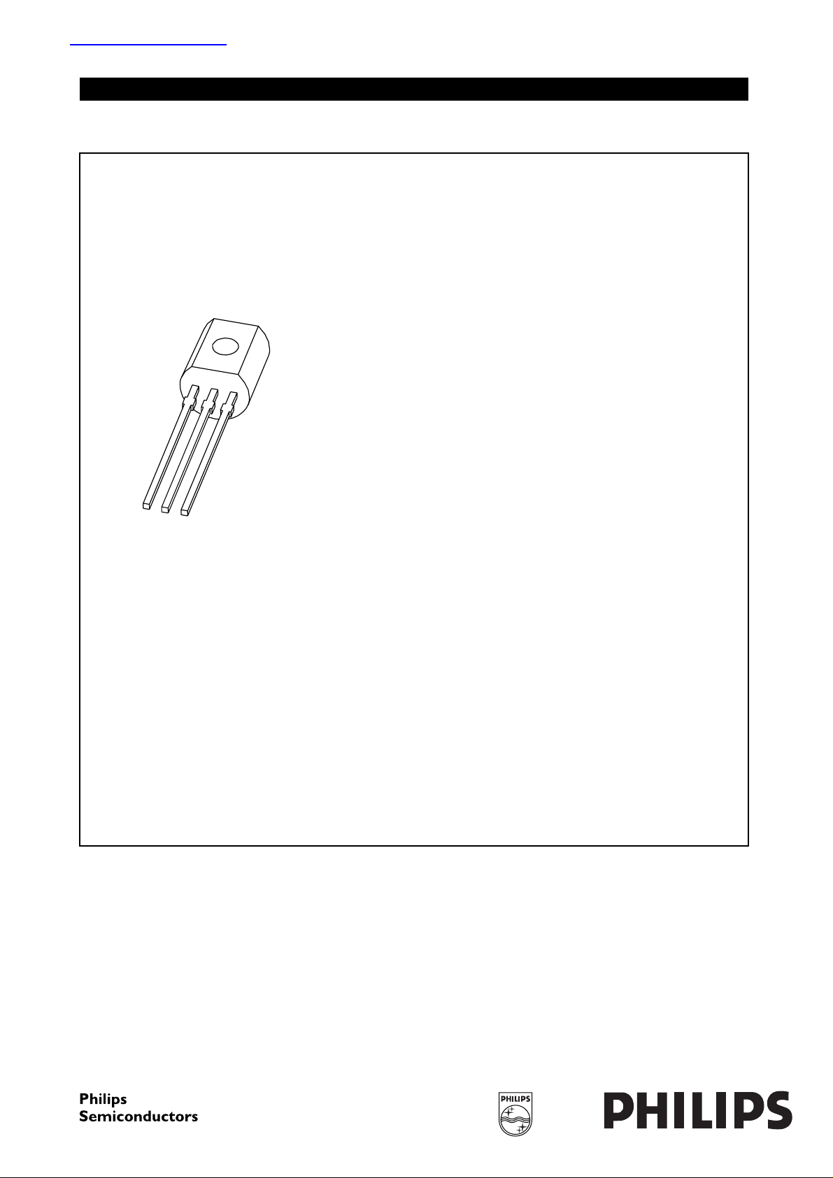
PINNING
PIN DESCRIPTION
1 base
2 collector
3 emitter
handbook, halfpage
collector-emitter voltage −50 V
collector current (DC) −3A
peak collector current −5A
equivalent on-resistance <150 mΩ
1
2
3
2
1
PNP low V
NPN complement: PBSS4350S.
transistor in a SOT54 plastic package.
CEsat
MAM285
3
MARKING
TYPE NUMBER MARKING CODE
Fig.1 Simplified outline (SOT54) and symbol.
PBSS5350S S5350S
LIMITING VALUES
In accordance with the Absolute Maximum Rating System (IEC 60134).
SYMBOL PARAMETER CONDITIONS MIN. MAX. UNIT
V
CBO
V
CEO
V
EBO
I
C
I
CM
I
BM
P
tot
T
stg
T
j
T
amb
collector-base voltage open emitter −−60 V
collector-emitter voltage open base −−50 V
emitter-base voltage open collector −−6V
collector current (DC) −−3A
peak collector current −−5A
peak base current −−1A
total power dissipation T
≤ 25 °C; note 1 − 830 mW
amb
storage temperature −65 +150 °C
junction temperature − 150 °C
operating ambient temperature −65 +150 °C
Note
1. Device mounted on a printed-circuit board, single sided copper, tinplated and standard footprint.
2001 Nov 19 2
Philips Semiconductors Product specification
50 V low V
PNP transistor
CEsat
PBSS5350S
THERMAL CHARACTERISTICS
SYMBOL PARAMETER CONDITIONS VALUE UNIT
R
th j-a
thermal resistance from junction to
in free air; note 1 150 K/W
ambient
Note
1. Device mounted on a printed-circuit board, single sided copper, tinplated and standard footprint.
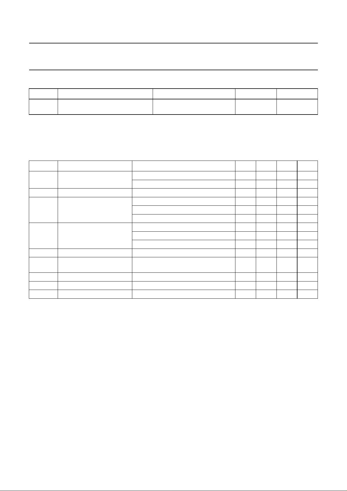
CHARACTERISTICS
T
=25°C unless otherwise specified.
amb
SYMBOL PARAMETER CONDITIONS MIN. TYP. MAX. UNIT
I
CBO
I
EBO
h
FE
V
CEsat
R
CEsat
V
BEsat
collector-base cut-off current VCB= −50 V; IE=0 −−−100 nA
V
= −50 V; IE= 0; Tj= 150 °C −−−50 µA
CB
emitter-base cut-off current VEB= −5 V; IC=0 −−−100 nA
DC current gain VCE= −2 V; IC= −500 mA 200 −−
V
= −2 V; IC= −1 A; note 1 200 −−
CE
= −2 V; IC= −2 A; note 1 100 −−
V
CE
collector-emitter saturation
voltage
IC= −500 mA; IB= −50 mA −−−100 mV
I
= −1 A; IB= −50 mA −−−180 mV
C
= −2 A; IB= −200 mA; note 1 −−−300 mV
I
C
equivalent on-resistance IC= −2 A; IB= −200 mA; note 1 − 120 <150 mΩ
base-emitter saturation
IC= −2 A; IB= −200 mA; note 1 −−−1.2 V
voltage
V
BE
f
T
C
c
base-emitter turn-on voltage VCE= −2 V; IC= −1 A; note 1 −−−1.1 V
transition frequency IC= −100 mA; VCE= −5 V; f = 100 MHz 100 −−MHz
collector capacitance VCB= −10 V; IE=Ie= 0; f = 1 MHz −−40 pF
Note
1. Pulse test: t
≤ 300 µs; δ≤0.02.
p
2001 Nov 19 3
 Loading...