

Page 1
查询PBSS2515F供应商
DISCRETE SEMICONDUCTORS
DATA SH EET
M3D425
PBSS2515F
15 V low V
Product specification
Supersedes data of 2001 Jan 26
CEsat
NPN transistor
2001 Sep 21
Page 2
Philips Semiconductors Product specification
15 V low V
CEsat
NPN transistor
FEATURES
• Low collector-emitter saturation voltage
• High current capabilities
• Improved thermal behaviour due to flat leads.
APPLICATIONS
• General purpose switching and muting
• Low frequency driver circuits
• LCD backlighting
• Audio frequency general purpose amplifier applications
• Battery driven equipment (mobile phones, video
cameras and hand-held devices).
DESCRIPTION
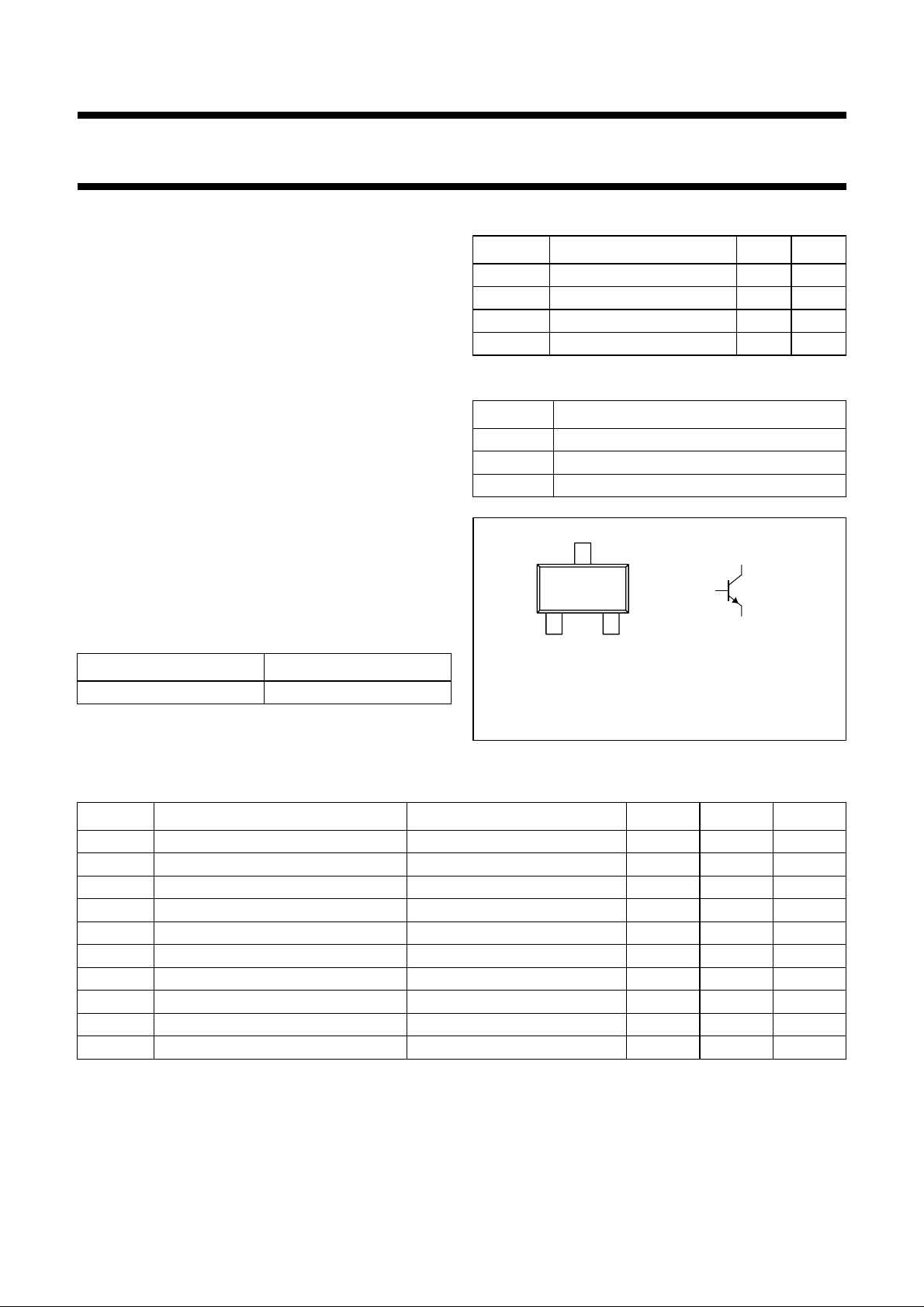
NPN low V
transistor in a SC-89 (SOT490) plastic
CEsat
package.
PNP complement: PBSS3515F.
PBSS2515F
QUICK REFERENCE DATA
SYMBOL PARAMETER MAX. UNIT
V
CEO
I
C
I
CM
R
CEsat
PINNING
PIN DESCRIPTION
handbook, halfpage
collector-emitter voltage 15 V
collector current (DC) 500 mA
peak collector current 1 A
equivalent on-resistance <500 mΩ
1 base
2 emitter
3 collector
3
1
3
MARKING
12
Top view
MAM410
2
TYPE NUMBER MARKING CODE
PBSS2515F 2A
Fig.1 Simplified outline (SC-89; SOT490) and
symbol.
LIMITING VALUES
In accordance with the Absolute Maximum Rating System (IEC 60134).
SYMBOL PARAMETER CONDITIONS MIN. MAX. UNIT
V
CBO
V
CEO
V
EBO
I
C
I
CM
I
BM
P
tot
T
stg
T
j
T
amb
collector-base voltage open emitter − 15 V
collector-emitter voltage open base − 15 V
emitter-base voltage open collector − 6V
collector current (DC) − 500 mA
peak collector current − 1A
peak base current − 100 mA
total power dissipation T
≤ 25 °C − 250 mW
amb
storage temperature −65 +150 °C
junction temperature − 150 °C
operating ambient temperature −65 +150 °C
2001 Sep 21 2
Page 3
Philips Semiconductors Product specification
15 V low V
NPN transistor
CEsat
PBSS2515F
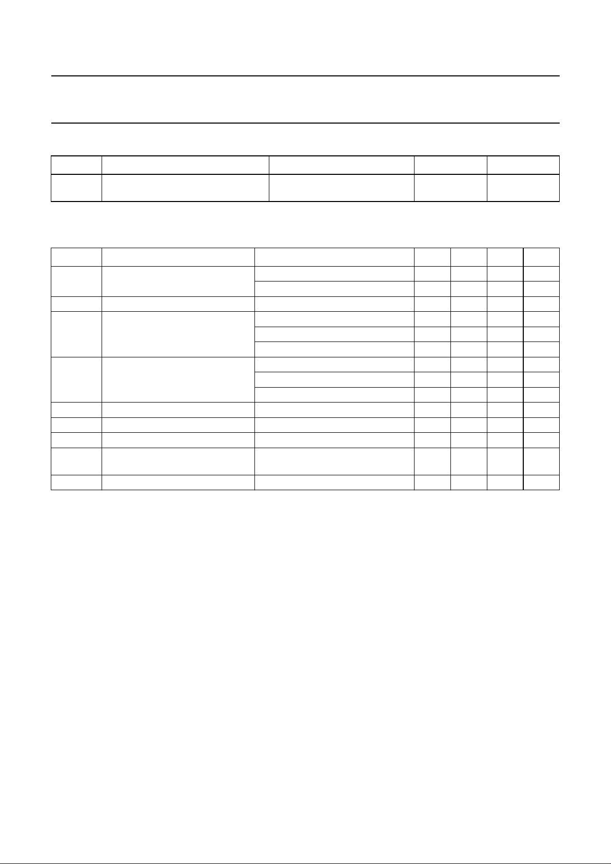
THERMAL CHARACTERISTICS
SYMBOL PARAMETER CONDITIONS VALUE UNIT
R
th j-a
thermal resistance from junction to
in free air 500 K/W
ambient
CHARACTERISTICS
=25°C; unless otherwise specified.
T
amb
SYMBOL PARAMETER CONDITIONS MIN. TYP. MAX. UNIT
I
CBO
I
EBO
h
FE
V
CEsat
R
CEsat
V
BEsat
V
BE
f
T
collector-base cut-off current VCB= 15 V; IE=0 −−100 nA
V
= 15 V; IE= 0; Tj= 150 °C −−50 µA
CB
emitter-base cut-off current VEB=5V; IC=0 −−100 nA
DC current gain VCE=2V; IC=10mA 200 −−
V
=2V; IC= 100 mA; note 1 150 −−
CE
=2V; IC= 500 mA; note 1 90 −−
V
CE
collector-emitter saturation
voltage
IC= 10 mA; IB= 0.5 mA −−25 mV
= 200 mA; IB=10mA −−150 mV
I
C
I
= 500 mA; IB= 50 mA; note 1 −−250 mV
C
equivalent on-resistance IC= 500 mA; IB=50mA − 300 <500 mΩ
base-emitter saturation voltage IC= 500 mA; IB= 50 mA; note 1 −−1.1 V
base-emitter turn-on voltage VCE=2V; IC= 100 mA; note 1 −−0.9 V
transition frequency IC= 100 mA; VCE=5V;
250 420 − MHz
f = 100 MHz
C
c
collector capacitance VCB= 10 V; IE=Ie= 0; f = 1 MHz − 4.4 6 pF
Note
1. Pulse test: t
≤ 300 µs; δ≤0.02.
p
2001 Sep 21 3
Page 4
Philips Semiconductors Product specification
15 V low V
600
handbook, halfpage
h
FE
400
200
0
−1
10
VCE=2V.
(1) T
(2) T
(3) T
amb
amb
amb
= 150°C.
=25°C.
= −55 °C.
NPN transistor
CEsat
(1)
(2)
(3)
110
2
10
I
C
MLD671
(mA)
PBSS2515F
2
IC (mA)
MLD673
3
10
1200
handbook, halfpage
V
BE
(mV)
1000
(1)
800
(2)
600
(3)
400
3
10
200
−1
110
10 10
VCE=2V.
(1) T
(2) T
(3) T
amb
amb
amb
= 150 °C.
=25°C.
= −55 °C.
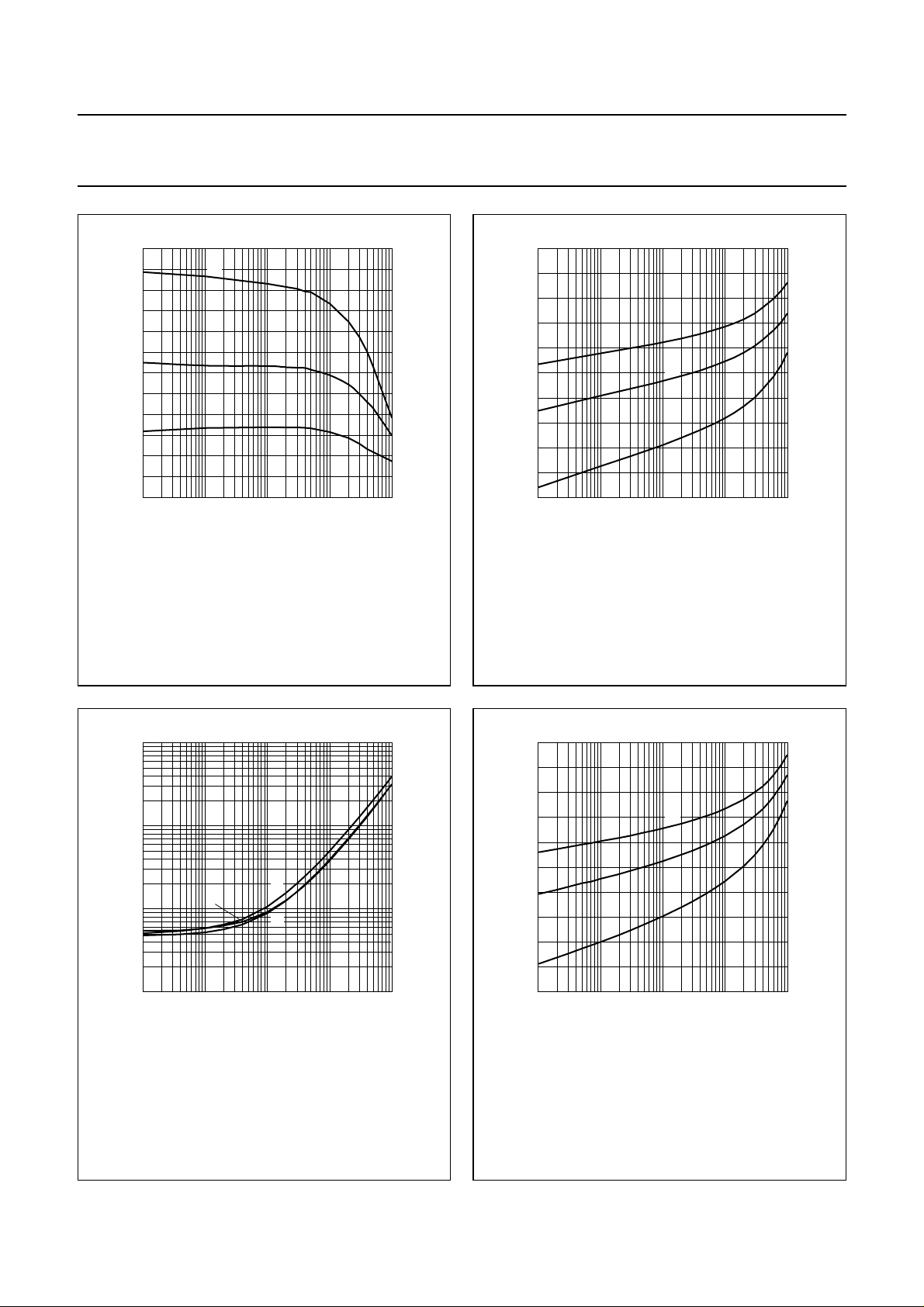
Fig.2 DC current gain as a function of collector
current; typical values.
2
10
I
C
MLD675
(mA)
3
10
handbook, halfpage
V
CEsat
(mV)
2
10
10
1
−1
10
IC/IB= 20.
(1) T
(2) T
(3) T
amb
amb
amb
= 150 °C.
=25°C.
= −55 °C.
(2)
(1)
(3)
110
Fig.3 Base-emitter voltage as a function of
collector current; typical values.
2
IC (mA)
MLD674
3
10
1200
handbook, halfpage
V
BEsat
(mV)
1000
(1)
800
600
(2)
(3)
400
3
10
200
−1
110
10 10
IC/IB= 20.
(1) T
(2) T
(3) T
amb
amb
amb
= 150 °C.
=25°C.
= −55 °C.
Fig.4 Collector-emitter saturation voltage as a
function of collector current; typical values.
2001 Sep 21 4
Fig.5 Base-emitter saturation voltage as a
function of collector current; typical values.
Page 5
Philips Semiconductors Product specification
15 V low V
1200
handbook, halfpage
I
C
(mA)
800
400
0
0
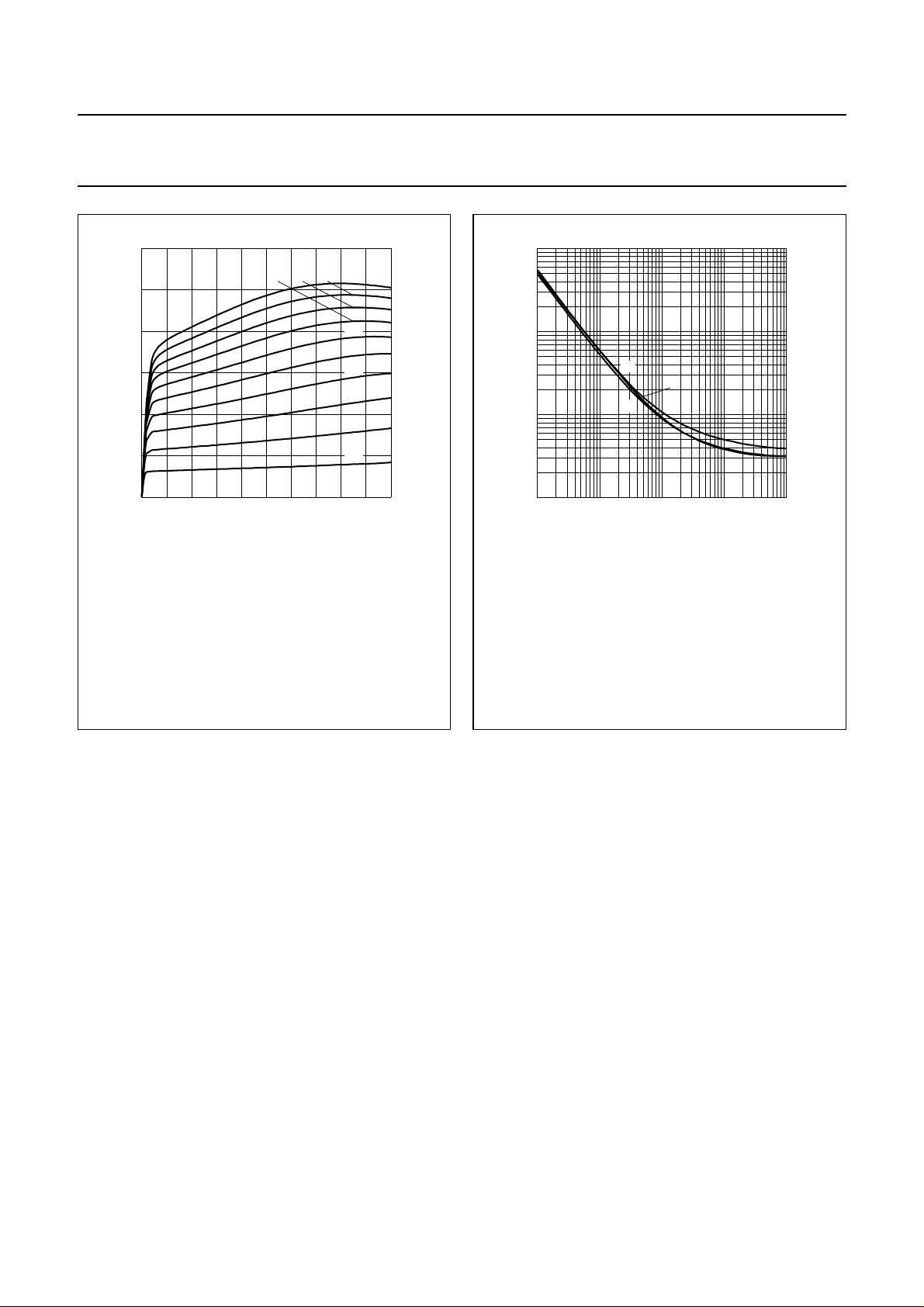
=25°C.
T
amb
(1) IB= 4.60 nA.
(2) IB= 4.14 nA.
(3) IB= 3.68 nA.
(4) IB= 3.22 nA.
210
NPN transistor
CEsat
(4)
468
(5) IB= 2.76 nA.
(6) IB= 2.30 nA.
(7) IB= 1.84 nA.
(8) IB= 1.38 nA.
Fig.6 Collector current as a function of
collector-emitter voltage; typical values.
MLD672
(2)(3)
(1)
(5)
(6)
(7)
(8)
(9)
(10)
VCE (V)
(9) IB= 0.92 nA.
(10) IB= 0.46 nA.
PBSS2515F
2
10
I
C
MLD676
(mA)
2
10
handbook, halfpage
R
CEsat
(Ω)
10
(1)
(2)
1
−1
10
10
IC/IB= 20.
(1) T
amb
(2) T
amb
(3) T
amb
−1
= 150 °C.
=25°C.
= −55 °C.
(3)
110
Fig.7 Collector-emitter equivalent on-resistance
as a function of collector current; typical
values.
3
10
2001 Sep 21 5
Page 6
Philips Semiconductors Product specification
15 V low V
NPN transistor
CEsat
PBSS2515F
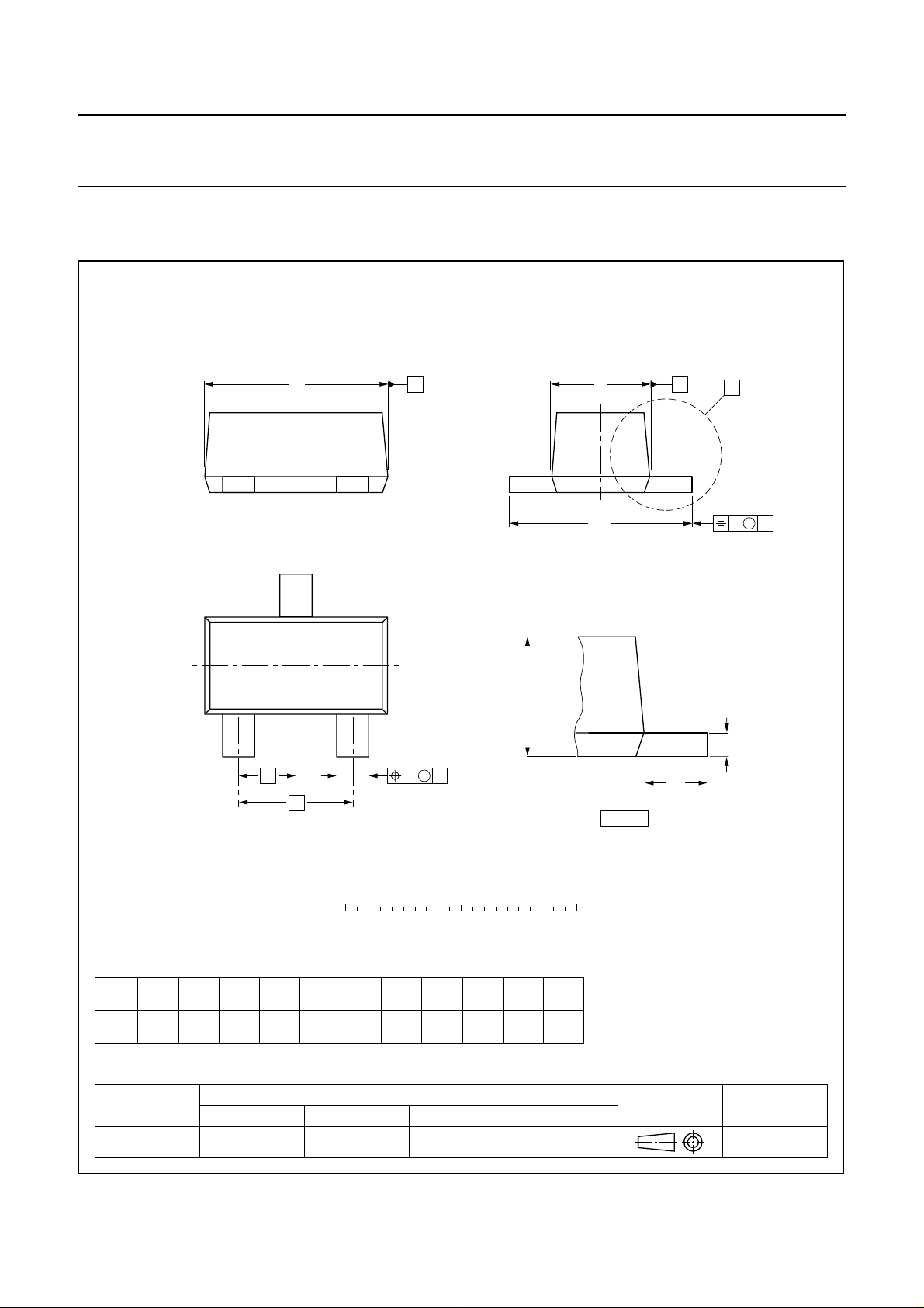
PACKAGE OUTLINE
Plastic surface mounted package; 3 leads SOT490
D
3
E
H
E
AB
X
v M
A
12
e
b
1
p
e
0 1 2 mm
DIMENSIONS (mm are the original dimensions)
UNIT b
A
0.8
0.6
0.33
0.23
mm
OUTLINE
VERSION
SOT490 SC-89
cD
p
0.2
1.7
1.5
0.95
0.75
0.1
IEC JEDEC EIAJ
e
E
1.0
REFERENCES
e
0.5
w M
1
B
H
1.7
1.5
scale
E
0.5
0.3
A
c
L
p
detail X
L
p
0.1
wv
0.1
EUROPEAN
PROJECTION
ISSUE DATE
98-10-23
2001 Sep 21 6
Page 7

Philips Semiconductors Product specification
15 V low V
DATA SHEET STATUS
DATA SHEET STATUS
Objective data Development This data sheet contains data from the objective specification for product
Preliminary data Qualification This data sheet contains data from the preliminary specification.
Product data Production This data sheet contains data from the product specification. Philips
Notes
1. Please consult the most recently issued data sheet before initiating or completing a design.
2. The product status of the device(s) described in this data sheet may have changed since this data sheet was
published. The latest information is available on the Internet at URL http://www.semiconductors.philips.com.
NPN transistor
CEsat
PRODUCT
(1)
STATUS
PBSS2515F
(2)
development. Philips Semiconductors reserves the right to change the
specification in any manner without notice.
Supplementary data will be published at a later date. Philips
Semiconductors reserves the right to change the specification without
notice, in order to improve the design and supply the best possible
product.
Semiconductors reserves the right to make changes at any time in order
to improve the design, manufacturing and supply. Changes will be
communicated according to the Customer Product/Process Change
Notification (CPCN) procedure SNW-SQ-650A.
DEFINITIONS
DEFINITIONS
Short-form specification The data in a short-form
specification is extracted from a full data sheet with the
same type number and title. For detailed information see
the relevant data sheet or data handbook.
Limiting valuesdefinition Limitingvalues givenare in
accordance with the Absolute Maximum Rating System
(IEC 60134). Stress above one or more of the limiting
values may cause permanent damage to the device.
These are stress ratings only and operation of the device
atthese orat anyother conditionsabovethose givenin the
Characteristics sectionsof the specification isnot implied.
Exposure to limiting values for extended periods may
affect device reliability.
Application information Applications that are
described herein for any of these products are for
illustrative purposes only. Philips Semiconductors make
norepresentation orwarrantythat suchapplications willbe
suitable for the specified use without further testing or
modification.
DISCLAIMERS
Life support applications These products are not
designed for use in life support appliances, devices, or
systems where malfunction of these products can
reasonably beexpected toresult inpersonal injury.Philips
Semiconductorscustomers usingorselling theseproducts
for use in such applications do so at their own risk and
agree to fully indemnify Philips Semiconductors for any
damages resulting from such application.
Right to make changes Philips Semiconductors
reserves the right to make changes, without notice, in the
products, including circuits, standard cells, and/or
software, described or contained herein in order to
improve design and/or performance. Philips
Semiconductors assumes no responsibility or liability for
theuse ofany oftheseproducts, conveysno licenceortitle
under any patent, copyright, or mask work right to these
products,and makesno representationsor warrantiesthat
these products are free from patent, copyright, or mask
work right infringement, unless otherwise specified.
2001 Sep 21 7
Page 8

Philips Semiconductors – a w orldwide compan y
Contact information
For additional information please visit http://www.semiconductors.philips.com. Fax: +31 40 27 24825
For sales offices addresses send e-mail to: [email protected].
© Koninklijke Philips Electronics N.V. 2001
All rights are reserved. Reproduction in whole or in part is prohibited without the prior written consent of the copyright owner.
The information presented in this document doesnot formpart of any quotation or contract, isbelieved tobe accurate and reliable and may bechanged
without notice. No liability will be accepted by the publisher for any consequence of its use. Publication thereof does not convey nor imply any license
under patent- or other industrial or intellectual property rights.
Printed in The Netherlands 613514/03/pp8 Date of release: 2001 Sep 21 Document order number: 9397 75008429
SCA73
 Loading...