

Page 1

PageWriter XLi
User’s Reference Guide
Page 2

Notice
About This Edition
Edition 8
Printed in the USA
Publi cation nu m ber M1 70 0 92909
The information in this
guide applies to th e
PageWriter XLi
cardiograph. This
information is subject to
change without notice.
Hewlett-Packard shall not
be liabl e for errors
conta i n e d herein or for
incidental or consequential
damages in connection with
the furnishing, performance,
or use of this material.
Edition History
Edition 1 May 1990
Editio n 2 July 1991
Editio n 3 January 1992
Edition 4 April 1993
Editio n 5 July 1993
Edition 6 June 1994
Editio n 7 January 1995
Edition 8 April 2000
Copyright
Copyrigh t © 2000
Hewlett-Packard Co.
3000 Minuteman Road
Andover, MA 01810-1099
USA
(978) 687 -1501
This do cument m a y no t b e
photoco pied, rep roduce d, or
translated to another
language without pr ior
written consent of HewlettPackard.
WARNING
As with electronic
equipment, Radio
Frequency (RF)
inter ference between the
cardiograph and any
existing RF transmitting or
receiving equipment at the
installation site, including
electrosurgical equipment ,
should be evaluated
carefully and any
limitations noted before the
equipment is placed in
service.
Radio frequency generation
from electrosur gical
equipment and close
proximity transmitters may
seriously degrade
performance.
Like al l el ec tronic de v ic es,
this cardiograph is
suscep tib le to electrostatic
discha rge (ESD).
Electrostatic discharge
typically occurs when
electrostatic energy is
transferred to the patient,
the elec trodes, or t h e
cardiograph. ESD may
result in ECG artifact that
may appear as narrow
spikes on the cardiograph
displa y or on the printed
report . Wh en ESD occurs,
the card iograph’s ECG
inter p retation ma y be
inconsistent with the
physic ia n’s inte rp retation.
Hewlett-Packard assumes
no liabil ity fo r fa ilures
resulting from RF
interference between HP
medical electronics and any
radio frequency generating
equipm e n t at le ve ls
exceedi ng those established
by applicable standards.
CAUTION
Use of accessories other
than th ose recom men ded by
Hewlett-Pac kard may
comprom ise product
performance.
THIS PRODUCT IS NOT
INTENDED FOR HOME
USE.
IN THE U.S., FEDERAL
LAW RESTRICTS THIS
DEVICE TO SALE ON OR
BY THE ORDER OF A
PHYSICIAN.
Medical Device
Directive
The PageWriter XLi
Cardiograph complies with
the requ irements of the
Medical Device Directive
93/42/EEC and carries the
mark accordingly.
0123
Author iz e d E Urepresentative:
Hewle tt-Packar d
Deutschland GmbH
Herrenbergerstrasse 130
D-71034 Boeblingen
Germany
Fax: +49-7031-14-2346
ii
Page 3
Safety Summary
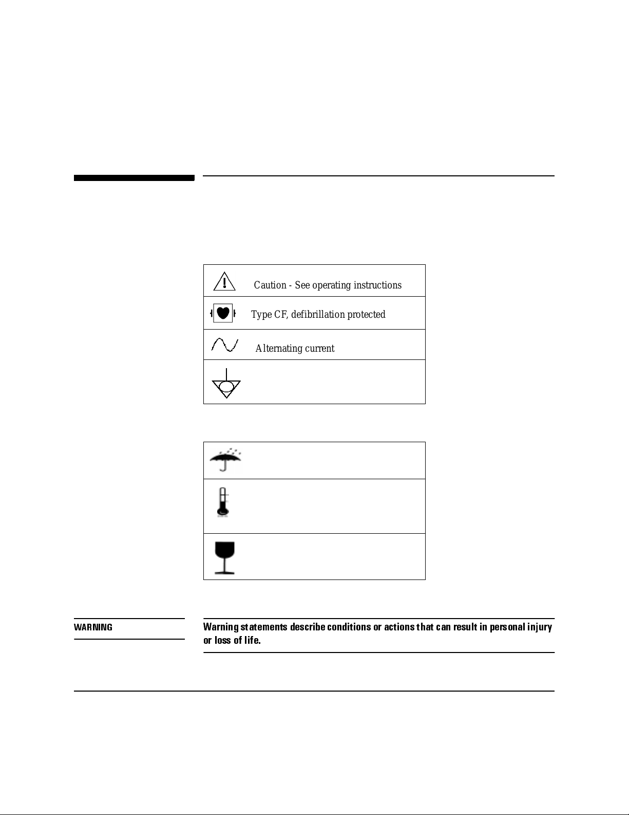
Safety Symb ols Marked on the Cardiogr aph
The following symbols are used on the cardiograph.
Caution - See operating instructi ons
Type CF, defib r illation prote cted
Alternating current
Equipotential (this is on the ground lug)
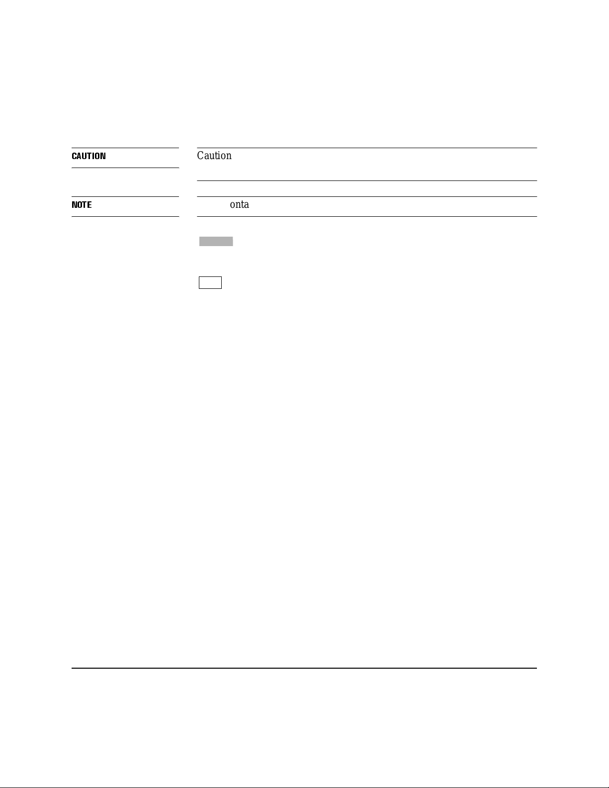
The following symbols appear on the cardiograph packaging.
Keep dry
:$51,1*
iii
Temperature and relative humidity
ranges
Fragile
Conventions Used in This M anual
:DUQLQJVWDWHPHQWVGHVFULEHFRQGLWLRQVRUDFWLRQVWKDWFDQUHVXOWLQSHUVRQDOLQMXU\
RUORVVRIOLIH
Page 4
&$87,21
Caution state ments describe conditions or actions that can result in damage to
the equipment or software.
12 7(
Notes contain additio nal information on cardiograph usage.
Softkey
represents the temporary key labels that appear on the keyboard
display.
represents keys on the front panel.
Key
iv
Page 5

Documentation
Map
Documentation Map
If you want to: Use this manual:
Verify that al l eq uipment is included Packing List
Record ECG’s Operating Guide
Enter pat ient ID
Make copies of ECG’s
Store ECG’s
Transmit or receive ECG’s
Troubleshoot problems
Maintain the car d iograph
Set up the cardiogra ph
Install the battery
Install the software
Load paper
Change applic ations
Install or use Pr ev iew Plus
Config u r e the cardiograph User’s Reference Guide
Prepare the patient
Maintain the car d iograph
Install and use the modem
v
Page 6

Documentation Map
If you want to: Use this manual:
Configure and use Special Applications User’s Reference Guide
Order supplies
Use filters
Understand an alysis Physician’s Guide
vi
Page 7

Contents
Safety Summary ...................................................................................................................... iii
Safety Symbols Marked on the Cardiograph .................................................................... iii
Conventions Used in This Manual ....................................................................................iii
Documentation
Map ...........................................................................................................................................v
Introduction
About This Manual ...............................................................................................................1-1
Acquiring an ECG
ECG Technique ..................................................................................................................... 2-1
Relaxing the Patient ........................................................................................................2-2
Preparing the Patient ....................................................................................................... 2-2
Preparing the Skin at the Electrode Positions ................................................................. 2-3
Securing the Electrodes ..................................................................................................2-4
Monitoring ECG Quality ......................................................................................................2-6
Quality Messages on the Cardiograph’s Display ............................................................2-7
Understanding the PageWriter XLi Special Applications
Overview ..............................................................................................................................3-1
Indic at ions for Use ........................ ........ .............. .............. ....... .............. .............. ........ ...3 -1
Understanding TPI Variables ..........................................................................................3-2
Understanding ACI TIPI Variables ................................................................................ 3-3
Using the TPI and ACI-TIPI Applications .....................................................................3-3
Analyzing an ECG with the Predictive Instruments .......................................................3-4
Generating Reports with the Special Applications Off .................................................. 3-5
Generating Reports with the Special Applications On ................................................... 3-6
Auto Analysis and the Default Choice ........................................................................... 3-7
Generating a STAT ECG Report .................................................................................... 3-8
Choosing Report Features
vii
Page 8

Contents
ECG Formats ........ .............. ........ .............. .............. ........ ............. .............. ........ ...................4-1
The Auto Report ............................................................................................................. 4-1
Auto Report Information ................................................................................................4-1
Manual Formats ..............................................................................................................4-6
The Manual Lead Sets ....................................................................................................4-6
ECG Storage
Advantages of Disk Storage ................................................................................................. 5-1
Storing Reports with the Special Applications Off ........................................................ 5-2
Storing Reports Using Auto Analysis and the Default Choice .......................................5-2
Automatically Storing Reports Using Forced Auto-Store .............................................. 5-2
Disk Handling and Maintenance Instructions ....................................................................... 5-3
Using the ECG-Log and Store-Log ...................................................................................... 5-4
Printing ECG Logs ..........................................................................................................5-7
Configuring Your Cardiograph
Using Configuration Menus ..................................................................................................6-1
Selecting Configuration Parameters .....................................................................................6-3
Understanding Global Configuration .................................................................................... 6-4
Interpretation Parameters. ............................................................................................. 6-10
Line Frequ ency .... ................................ ........................ ......................... ........................ 6-11
Selecting Custom Lead Groups .................................................................................... 6-11
Selecting AutoCopy ......................................................................................................6-11
Selecting ECG Management Parameters ...................................................................... 6-12
Selecting Battery Timeout Periods ............................................................................... 6-12
Setting a Password ........................................................................................................6-13
Turning Off Unused ID Fields ............................................................................................6-13
Storing the Configuration Information ......................................................................... 6-14
Using a Stored Configuration ....................................................................................... 6-15
Printing the Configuration ............................................................................................6-16
Setting Up Your Cardiograph for Transmitting ECGs
Transmitting ECGs Directly .......................................................... .......... .......... .......... .........7-3
Configuring the Cardiograph to Transmit ECGs Directly .............................................. 7-4
viii
Page 9

Contents
Transmitting ECGs by Telephone to Another Site ............................................................... 7-5
Installing the Modem (For United States use only) ........................................................ 7-5
Connecting a Telephone to the Same Line as the Modem ............................................. 7-7
Configuring the Cardiograph for Modem Usage ............................................................ 7-7
Entering the Phone Number ............................................................................................ 7-9
Configuring the Cardiograph for AutoDial .................................................................... 7-9
Installing the Modem on the Cart ................................................................................. 7-10
Transmitting ECGs by FAX to Another Site ......................................................................7-11
Installing the FAX/Modem ........................................................................................... 7-12
Connecting a Telephone to the Same Line as the FAX/Modem .................................. 7-14
Configuring the Cardiograph for FAX Usage .............................................................. 7-14
Entering the Phone Number .......................................................................................... 7-15
Transmitting an ECG via FAX .....................................................................................7-16
Printing an ECG on an HP LaserJet Printer ........................................................................ 7-17
Setting up the LaserJet Printer ............................................................................................7-18
Configuring the Cardiograph to Print ECGs on the HP LaserJet .................................7-18
Receiving ECGs ..................................................................................................................7-20
Configuring the Cardiograph to Receive ECGs Directly ............................................. 7-20
Configuring the Cardiograph to Receive ECGs via Modem ........................................ 7-21
Receiving an ECG via FAX ..........................................................................................7-21
Configuring the Cardiograph to Receive via FAX ....................................................... 7-22
Receiving ECG Reports from an HP 5600C ECG Management System ..................... 7-22
Receiving ECGs from an HP M1730A or M3700A TraceMaster ECG Management System
7-23
Troubleshooting
Troubleshooting Leads Off ...................................................................................................8-1
Troubleshooting ECG Noise ................................................................................................. 8-1
Understanding Error Messages ............................................................................................. 8-3
Calling for Assistance ..................................................................................................... 8-3
Solving Eq u i p m e n t Pr o b l e m s .... ................ ........................ ................................. .................. 8-3
Supplies
Availability ...........................................................................................................................9-1
ix
Page 10

Contents
Lead Systems
Frank Le a d s ...................... ........................ ........................ ................................. ................... A-1
Special Lead Configurations ................................................................................................ A-2
V3R, V4R, V7 and V8 ...................................................................................................A-2
VX1, VX2, VX3 and VX4 .............................................................................................A-2
Glossary
x
Page 11

1 Introduction
About This Manual
This guide contains reference information and configuration instructions for
experienced PageWriter XLi cardiograph users. If you are unfamiliar with
using this cardiograph, please view the videotape tutorial Using the Hewlett-
Packar d PageWriter XL Cardiographs. For additional help on using your
cardiogra p h refer to the HP PageWriter XLi Operating Guide.
1
1-1
Page 12

About This Manual
1-2 Introduction
Page 13
2 Acquiring an ECG
One of the most important aspects of recording a clear ECG is good ECG
technique. This chapter include s a review of recommended ECG technique as
well as information about using the pat ient module.
12 7(
Computerized ECG analysis should always be reviewed by a qualified
physician.
ECG Te chnique
ECG technique is very important, both to avoid difficulty when taking the
ECG and to achieve the best quality result. There are three key aspects of
good ECG technique:
l
Helping the patient to relax.
2
l
Preparing the patient for electrode connection.
l
Using the patient module to check lead connections.
For best results, perform the following steps in the order given. More details
on good technique follow this li st.
l
Check that the patient is comfortable and relaxed. Reassure the
patient that the procedur e is painless.
l
If possible, place the patient away from electrical fixtures and their
power cords, and away from the cardiograph’s power cord if AC
pow er is on.
l
Expose the patient’s forearms, lowe r legs, and chest.
l
Beginning with the right leg position, apply electrolyte and atta ch
electrodes.
2-1
Page 14

ECG Technique
12 7(
Disposable ele ctrodes , when used properly, may be used for a cceptable E CGs.
For best results, prepare the skin and carefully follow manufactur er’s usa ge
instructions .
Relaxing the Patient
The more the patient relaxes, the less the ECG will be affected by noise. Your
good technique he lps the pati ent relax. You can help the patien t to rela x by the
following:
l
Make sure the patient is lying down and comfortable. The patient’s
arms and hands must be relaxed. If the table is too narrow, place the
patient’s hands under the buttocks to prevent muscle tension in the
arms.
l
When possible, take the ECG in a quiet room or area where others
can’t see the patient. Privacy is important to relaxation. Draw the
curtains around the bed area when taking the ECG in a room with
other people.
l
Gain the patient’s confidence by expla ining the test and that it won’t
hurt.
l
Your calm, relaxed attitude will help put the patient at ease.
l
Don’t let the patient move unnecessarily. It’s also best to avoid all
conversation during the actual ECG recording to keep the patient as
still as possible.
Preparing the Patient
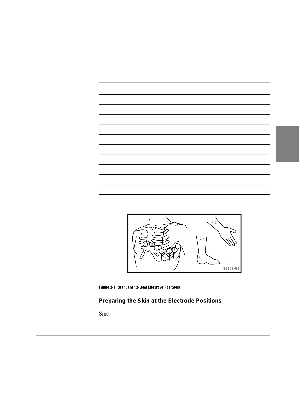
Selecting th e Electrode Positio ns m, Table 2-1, shows the proper electrode
positions for taking an ECG. Put the electrodes in the correct anatomical
locations accordi ng to inf ormation in Figure 2-1.Additional information
concerning other lead systems may be found in Appendix A.
The tip of each lead wire is lettered and color cod ed for easy lead
identification. For example, make sure that the RA lead wire and electrode
connect to the right arm and the RL lead wire and electrode connect to the
right leg.
2-2 Acquiring an ECG
Page 15
ECG Technique
T able 2-1 Standard 12-Lead Electrode Positions
Lead Position
RL On the right leg (inside calf, midway betw een knee and ankle)
LL On the left leg (inside calf, mid way between knee and ankle)
RA On the right arm (on the inside)
LA On the left arm (on the inside )
V1 Fourth intercostal sp ace, at right sternal margin
V2 Fourth intercostal space, at left sternal margin
V3 Midway between V2 and V4
V4 Fifth intercostal space at lef t midclavicu lar line
V5 Same transverse level as V4 , o n an terior axillary l in e
V6 Same transverse level as V4, at left midaxillary line
2
)LJXUH6WDQGDUG/HDG(OHFWURGH3RVLWLRQV
Preparing the Skin at the Electrode Positions
Since dry skin is a relatively poor elec trical conductor, you must prepare the
skin to assure good contact between the skin and the electrode. Before
2-3
Page 16

ECG Technique
securing the electr odes, you must lower the skin resistance at the electrode
site by:
l
Making sure that all electrodes are clean and bright. (Dirty or
corroded electro des pre vent a good electrical connection.)
l
Avoiding bony areas. Select flat , f le shy sites. You don’t have to shave
hair from the skin unless the hair is very thick.
l
Rubbing the skin briskl y with t he edge of the electr ode or a gauz e pad
until the skin is slightly r ed, but not bruised.
l
Applying electrol yte to the prepared areas on the skin. Rub some
electrolyte into the skin, but leave a slightly moist residue. Do not
spread electroly te o n the ch est area between electrodes . This will
cause distorted waveforms on the ECG.
127(
Do not use alcohol or acetone pads in place of the electroly te because they
impair the electrode con tact with the skin.
Securin g the Electro des
We have included two types of electro des in the accessory box:
l
Metal plate limb electrodes, held in place on the patient by rubber
straps.
l
Welsh cup chest electrode s, he ld in place by suction.
Securing the electrode s is a key part of good ECG technique and getting a
good ECG trace. To avoid jittery wavef orms, make sure th at the ele ctrodes are
secure. Do not overtighten limb plate electrodes, since this might cause
discomfort which results in muscle artifact on the waveforms.
Fasten the electrodes to the chest positions by squeezing the rubber bulb of
the suction cup. See Figure 2-3. The bulb should be partially deflated when
the electrode is firmly attached to the chest.
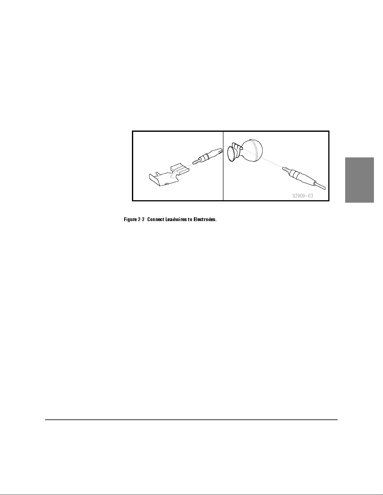
A good test for firm ele ctrode contact i s to gras p the electr ode and tr y to move
it. If it moves easily, the elect rod e connection is too loose. If it digs into the
flesh, the electrode is too tight. Do not allow the chest electrodes to move in
any way . Check the patient module display for indic at ions that the
connections are good. Ideally , the noise bar should remain in the green zone.
2-4 Acquiring an ECG
Page 17
ECG Technique
Do not leave suction electrodes connected to the chest for prolonged periods.
The suction can cause intrade rmal hemorrhaging.
)LJXUH&RQQHFW/HDGZLUHVWR(OHFWURGHV
2
2-5
Page 18

Monitoring ECG Quality
)LJXUH)DVWHQ(OHFWURGHV
Monitoring ECG Quality
There are three ways that the PageWriter XLi helps you monitor the quality of
your ECG recordings.
l
Using the patient module displa y
l
Using the preview screen
l
Observing quality messages on the cardiograph’s display
2-6 Acquiring an ECG
Page 19

Monitoring ECG Quality
You can stop the recording before or during printing if you see arti fac t or
other ECG waveform problems on the screen. Modify lead placement or
improve patient preparation and resume recording the ECG.
For further instructions on using the patient module display and the preview
screen, refer to the PageWriter XLi Operating Guide.
Quality Messages on the Cardiograph’s Display
After you start an Auto ECG recording, the cardiograph’s display will show
messages which indic ate the quality of the recording. If t here is m inimal noise
and all electrod es are s ecu r el y attach e d, the me ssa ge "‘EC G ok’’ will appear.
Some messages indicate problems with the leads. They list the condition and
the action to take. There are four conditions which affect the ECG:
l
Leads off
l
AC noise
l
Artifact
l
Baseline wander
2
If any of these conditions are severe, the mess ag e dire ct s you to retry the
recording. Correct the problem and then resume recording the ECG.
2-7
Page 20

Monitoring ECG Quality
2-8 Acquiring an ECG
Page 21

3 Understanding the PageW riter XLi Special
Applications
Overview
The ACI TIPI (Acute Cardiac Ischemia - Time Insensitive Predictive
Instrument) and the TPI (Thrombolytic Predictive Instrument) are software
products that enhance the computer-assisted ECG analysis capabilities of the
PageWriter XLi Cardiograph. These "Predictive Instruments" generate 0100% Predicted Probabili ty scores of ACI (Acute Cardiac Ischemia) and
patient outcome with and without thrombolytic therapy for acute myocardial
infarction (AMI). These pr edicted probabilities are based on ECG featur es,
patient age, gender, blood pressure, chest pain status and time since ischemic
symptom onset. The cardiograph can be configured to automatically print
these probabilit ies on the Auto ECG report.
3
Indications for Use
The ACI-TIPI is intended for use as an aid to clinicians in the diagnosis and
triaging decision process of patients with ACI, which includes unstable
angina pectoris and acute myocardial infarction (AMI).
The TPI is intended for use as an aid to clinicians identifying which patients
with AMI are appropriate candidate s for thrombolytic ther apy . TPI is intended
for adult patients, aged 35-75, diagnosed with symptoms of acute myocardial
infarction.
These programs can be used in real-time and retrospective settings since they
rely on information that is rea dily available in the emergency depar tment
(ED), or by retrospective review of the patient’s medical record. The
emergency physi cian’s real-time decision making process is aided by havin g
the predictive instruments incorporated into the electrocardiograph. The
predictive scores, once acquired, can then be used along with actual patient
outcome to help improve patient management practices retrospectively.
3-1
Page 22
Overview
The predictive instr uments provide the physician with tools to:
l
Aid diagnosis and triage of some patients with symptoms suggestive
of ACI
l
Identify those patie nts most likely to benefit from thrombolytic
therapy
l
Facilitate the earliest possible administration of thrombolytic therapy
127(
12 7(
For intended use and contraindication information, consult the Predictive
Instrument Physician’s Guide for important information.
Understanding TPI Variables
There are nine predictors of thro mbolytic-related benefits and risks which
include six clinical factors and detailed information on three ECG features.
The six clinical factor s are:
l
Time since ischemic onset
l
Patient age
l
Patient gender
l
Patient Blood Pressure (systolic and diastolic)
l
Patient’s history of diabetes
l
Patient’s history of hypertension
For each of the clinical factors listed above, patient data must be entered in
order to produce a TPI report.
3-2 Understandin g the P ageWriter XLi Speci al Applications
Page 23
Overview
The three ECG features are:
l
the presence or absence of pathological or significant Q waves
l
the presence and degree of ST segment elevati on or depression
l
the presence and degree of T wave elevation or inversion
Understanding ACI TIPI Variables
Seven variables are used to predict Acute Cardiac Ischemia. These variables
include four clinical factors and detailed information on three ECG features.
The four clinical factor s are :
l
the presence or absence of chest pain or pressur e, or left arm pain
l
whether chest pain or pressur e, or lef t arm pain is the patient’s most
important present ing symptom
l
patient age
l
patient gender
127(
For each of the clinical factors listed above, patient data must be entered in
order to produce the ACI-TIPI report.
The three ECG features are:
l
the presence or absence of pathological or significant Q waves
l
the presence and degree of ST segment elevati on or depression
l
the presence and degree of T wave elevation or inversion
The exclusionary cases for both the TPI and ACI-TIPI applications are listed
in the Predictive Instrument Physician’s Guide. Please refer to this document
for this information.
Using the TPI and ACI-TIPI Applications
To use the TPI and ACI-TIPI applications, you must configure the
cardiograph and enable the appli cations. There are several types of reports
that are produced by the cardiograph. These reports are summarized in Table
3-1.
3
3-3
Page 24

Overview
T able 3-1 PageWriter XLi Reports
Report Type Contents of Report Notes
Standard 09 (Std 09) ECG waveforms, mea-
surements, ECL 09 Adult
Interpretation
Standard P4 (Std P4) ECG waveforms, mea-
surements, ECL P4 Pediatric Interpretation
ACI-TIPI (T0) ECG waveforms, TIPI
Analysis,
No Risk Management
Report
Risk Managemen t Risk Management Report
—1 page summarizing
clinical information and
can be used by the Clinician to docu ment clinical
decisions
TPI (H0) ECG waveforms, TPI
Analysis
Only available when
T0 is enabled
The ACI-TIPI
Report will also be
printed.
Analyzing an ECG with the Predictive Instruments
The flexibility of the Page Writer XLi allows you to configure the Predictive
Instruments based on the type of patients presenting in your clinical setting.
Using the Configuration Menu, you can set up your cardiogr aph to provide
the desired analysis .
When first turned on the PageWriter XLi cardiograph will have the Special
Applications turne d off. The Special Application choices are part of the
Global Configuration Menu and enable access to the following settings.
3-4 Understandin g the P ageWriter XLi Speci al Applications
Page 25
T able 3-2 Special Applications Setti ngs
Overview
Parameter Choices
Research Leads Off/VX 1-V X 4 / V 4 R-V 8 Off
Default Adul t Cr iteria 09/P4 09
Default Pediatric Criteria 09/P4 P4
Patient ID Criteria On/Off Off
ACI-TIPI On/Off Off
Risk Mgmt. On/Off Off
Risk Range 0%-100% TPI On/Off Off
Screening On/Off Off
Leads Normal/Cabrera Normal
Storage Mode Standard/Special Normal
VCG Off/vcg1/vcg2/vcg3/vcg4 Off
Default Storage Cri teria Def Adult/Ped, TIPI, TPI Def Adult/Ped
Default value when Special Apps =
off
3
It is important to under stand that it is possi ble to set the Defaul t Adult Crite ria
and the Default Pediatric Criteria to be either 09 or P4. This flexibility is
designed for unusual clinical settings, and you should always be aware of just
how your cardiograph is set up.
Generat ing Reports with the Special Applications Off
This method of working enables any kind of report to be generated, however
it does not allow for generation of multiple simul taneous reports. Through the
top level "Auto Analysis" menu, you can specify the kind of report to be
made. There are five choices availa ble: Adult, Pediatric, TIPI, or TPI, or
Default.
3-5
Page 26

Overview
F3
For each of these report options, here are the resulting reports given that
Special Applications are Off and the Auto button has been pressed:
l
Adult - The XLi will do an 09 report (regardless of patient age).
l
Pediatric - The XLi will do a P4 report (regardless of patient age).
l
TIPI - The XLi will do a TIPI report. A Risk Management report wi ll
not be generated.
l
TPI - The XLi will do a TPI report. TPI screening will not occur.
l
Default - The XLi will do an 09 report if the age is unspecified or
above 15 years. The XLi will do a P4 report if the age is 15 years or
less.
1. From the main display, press the key until ’Auto Analysis’ appears.
F1
2. Press the key to select the desired report format.
Generat ing Reports with the Special Applications On
It is possible to configure the PageWriter XLi to produce multiple reports.
When the settin g for Specia l Applic ation s is turned t o On, and t he Auto butt on
is pressed, there are five choices of reports available - Adult , Pedia tric, ACITIPI, TPI or Default. The first four choices and their resulting outcomes are
described below:
l
Adult - The XLi wil l do the Default Adult Criteria Report (regardless
of the patient’s age).
l
Pediatric - The XLi will do the Default Pediatric Criteria Report
(regardless of the patient’s age).
l
ACI-TIPI - The XLI will do a TIPI report. Also, if the Risk
Management Report i s set to o n in the S pecial Applicati ons M enu and
the ACI-TIPI Report risk factor falls within the limits set up, a Risk
Management Report will be produced.
l
TPI - The XLi will do a TPI report. TPI Screening will not occur.
3-6 Understandin g the P ageWriter XLi Speci al Applications
Page 27

Overview
Auto Analysis and the Default Choice
If the Default choice is selected from the Auto Analysis menu, multiple
reports may be produced when the Auto button is pressed, depending on what
has been enabled in the Special Applications in the Global Configuration
Menu.
l
TPI - If TPI is on and TPI Screening is off, a TPI report will be
generated. If TPI is on and TPI Screening is On and the TPI Analysis
Criteria are met, a TPI report will be gene rate d. If both TPI and TPI
Screening are on, but the TPI Analysis Crite ria are not met, a TPI
report will not be generated.
l
ACI-TIPI - I f ACI-TIPI is on, this will be the next report produced. If
the Risk Management Report is also on and the ACI-TIPI calculated
risk is between the low and high risk limits as set up in the Special
Applications, then a Risk Management report will be produced.
l
Standard ECG (consisting of one of the following):
Patient ID Criteria Off - The XLi will do the Default Adult Repor t if
the patient’s age is spe cifie d as ove r 15. If the patie nt’s age is 15 years
or under, the Default Pediatric Report will be produc ed.
Patient ID Criteria On and Patient ID Criteria Loaded - This custom
interpretation report will be generated.
Patient ID Criteria On but Patient I D Criteria No t Loaded - A Null
report will be produced.
Patient ID Criteria On but Patient I D Criteria No t Entered by the
User - The XLi will do the Default Adult Report if the patie nt’s age is
specified as ove r 15. If the patie nt’s age 15 yea rs or under, the Defa ult
Pediatric Report will be produc ed.
3
l
Vectorcardiography - If VCG is on and at least one of the X, Y or Z
leads is included as a rhythm lead in the repor t type , a nd Research
leads is set to off, then the XLi will produce a VCG report.
3-7
Page 28

Overview
Generating a STAT ECG Report
If your cardiograph has been configured with the Special Applications On,
and with TPI and/or TIPI interpre ta tions enabled, you may omit these
interpretations by running a "STAT" ECG. A STAT ECG is guaranteed to
generate a single stand ard repor t (typically 09 Adult Criteria or P4 Pediatric
Criteria) without the need for Patient ID information. A STAT ECG is
initiated by pressing the AUTO key twice in succession. A STAT report is
produced even if "Print Auto = OFF" in the global configuration menu.
3-8 Understandin g the P ageWriter XLi Speci al Applications
Page 29

4 Choosing Report Featu res
This chapter describe s the vari ous ECG reports and how to print the Extended
Measurements report.
ECG Formats
The Auto Report
Twelve-lead Auto reports display a ten second ECG in an Auto 3 x 4, Auto 3
x 5, Auto 4 x 4 or Auto 6 x 2 format. The Auto 3 x 4 format displays
consecutive 2.5 second segments of 12 leads, three leads at a time. The Auto
3 x 5 format displays consecutive 2 second segments of 12 leads with the 5th
lead column showing the extended pediatric leads, V3R, V4R, and V7. The
Auto 4 x 4 format displays consecutive 2.5 sec ond segments of 12 leads with
the 4th row consisting of the extende d rese arch leads VX1-VX4 or V3R,
V4R, V7, and V8. The Auto 6 x 2 format displays consecutive 5 second
segments of 12 leads, six leads at a time. One or three leads c an be displa yed
as rhythm strips at the bottom of Auto 3 x 4 and Auto 3 x 5 reports. The
rhythm strips show the same 10 second s egments as in the Auto 3 x 4 or Auto
3 x 5 section of the report. The Auto 4 x 4 report can show 1 rhythm strip.
4
Auto Report Information
The Auto report may be printed with patient I D inform ation only or with
various types of analysi s information included. You can select which
information appear s on the printe d report. See Chapter 6, Configuri n g Your
Cardiograph, for informat ion on choosing which features will be printed on
the report.
4-1
Page 30

ECG Formats
Basic Measurements Re port. The Basic Measu rements report has pat ient ID
information and basic measurements for the ECG. These measurements,
which include heart rate, interval and axis measurements, are in the table
below with their abbreviations on the report.
T able 4-1 Basic Measurements
Symbol Description Units
Rate heart rate beats per minute
PR PR interval milliseconds
QRSD QRS duration m illiseconds
QT QT interval milliseconds
QTc QT interval corrected for rate milliseconds
P Frontal P axis degrees
QRS Frontal mean QRS axis degrees
T Frontal T axis degrees
4-2 Choosing Report Feat ures
Page 31

ECG Format s
Severity Report. This report shows a summary statement of the severity
derived from the ECG interpret ation. There are five ECG severities:
l
Normal
l
Otherwise Normal
l
Borderline
l
Abnormal
l
Defective Data
Interpretive R ep o rt. The Interpr etive report includes basic measurement
information as well as statements from the analysis of the extended
measurements derived from medica l and technical criteria. This report a lso
shows a summary statement of the severity of the ECG interpretation.
Reasons Report. The Reasons report includes all of the features included on
the Interpretiv e report as well as summarized reasons for each interpretative
statemen t. The reason for each state me n t prov ide s a sum m ary of the cri te ria
which were met in order to print the interpretive statement.
4-3
4
Page 32

ECG Formats
Menu
Find
Extended M ea su rem ents Report. The Extended Measurements report lists
the measurements which determine a suggested interpretation. This two page
report summarizes the morphology and rhythm characteristics for the
individual lead waveforms and rhythm groups in the ECG.
To print the Extended Measurements report for a stored ECG:
1. Insert the disk wit h the ECG for which you want extended measurements.
2. Press until the following display appears.
Transmit Store Config CheckDisk Files
3. Press . The display becomes:
4. Press . The display becomes:
5. Press or until the correct patient ID number appears.
Files
Delete Log Edit Print Files
Print
123456 09-23-90 11:25:51 AM
Select Print Next Previous More
Next
Then press . Or:
l
If you know the ID number of the ECG you want to print, press ,
Previous
Select
then .
ore
4-4 Choosing Report Feat ures
Page 33

ECG Format s
More
Extended
l
T ype the patient ID number, then press . The most recent ECG
Enter
with that patient ID number appears. If you want a different ECG for
that patient, you must scroll through the list by pressing .
Then press .
Select
Previous
Continue with the followin g steps .
6. Press and then . If your cardiograph has been configured to
Select
Print
print "Choice", the following display appears.
Choose desired analysis for print.
None Measure Interp. Reasons More
l
Press and the following display appears.
Choose desired analysis for print.
Extended Sev.only More
See Chapter 6, Configuring Your Cardiograph for information on
configuring your cardiograph to print the Extended Measurements report if it
hasn’t been set up to do so.
7. Press .
8. The message, "Printing 1 of 1 ECG(s)’’ will appear and the two-page
Extended Measurements report will be printed on the cardiograph.
You can also configure the cardiograph for "Choice" in order to print this
report when copying an ECG.
4
4-5
Page 34

ECG Formats
Manual Formats
Manual ECGs print continuously after you press until you press
Stop
. Manual ECGs are printed as the ECG waveform occurs.
Manual
The Manual Lead Sets
Manual mode is used for monitorin g rh ythm over an e xtended pe riod. Besides
standard lead combinations, you can configure your own lead combinations
for Custom Manual 3 or 6 leads. See Chapter 6, Configuri ng Your
Cardiograph for information a bout selecting different lead combinations in
Manual mode. Besides the conventio nal 12 leads, you may use one of the
following sets of supple mental leads:
pediatric leads V4R, V3R, V7
or Frank leads X, Y, Z
or generic research le ads VX1, VX2, VX3, VX4
or right chest / post erior research
leads
V4R, V3R, V7, V8
The following tables show lead selec tion choices.
T able 4-2 Manual Standard Leads
Number of
Leads
3 I, II, III
aVR, aVL, aVF
V1, V2, V3
V4, V5, V6
6 I, II, III, aVR, aVL, aVF
V1, V2, V3, V4, V5, V6
12 I, II, III, aVR, aVL, aVF, V1, V2, V3, V4, V5, V6
4-6 Choosing Report Feat ures
Lead Cho ices
Default Custom Lead
Choices
I, aVF, V2
II, aVF, V1, V2, V4, V6
Page 35

T able 4-3 Manual Standard + Pediatri c Leads
ECG Format s
Number
of Leads
3 I, II, III
aVR, aVL, aVF
V1, V2, V3
V4, V5, V6
V3R, V4R, V7
6 I, II, III, aVR, aVL, aVF
V1, V2, V3, V4, V5, V6
I, aVF, V2, V3R, V4R, V7
12 |I, II, III, aVR, aVL, aVF, V1, V2, V3, V4, V5, V6
I, II, aVF, V4R, V3R, V1, V2, V3, V4, V5, V6, V7
Number
of Leads
3 I, II, III
aVR, aVL, aVF
V1, V2, V3
V4, V5, V6
X, Y, Z
Lead Cho i ce s
T able 4-4 Manual Standard + Frank Leads
Lead Cho i ce s
Default Custom Le ad
Choices
I, aVF, V2
II, aVF, V1, V2, V4, V6
Default Custom Le ad
Choices
I, aVF, V2
4
6 I, II, III, aVR, aVL, aVF
V1, V2, V3, V4, V5, V6
I, aVF, V2, X, Y, Z
12 I, II, III, aVR, aVL, aVF, V1, V2, V3, V4, V5, V6
I, II, aVF, V1, V2, V3, V4, V5, V6, X, Y, Z
II, aVF, V1, V2, V4, V6
4-7
Page 36

ECG Formats
T able 4-5 Manual Standard + Generic Research Leads
Number
of Leads
Lead Cho i ce s
3 I, II, III
aVR, aVL, aVF
V1, V2, V3
V4, V5, V6
VX1, VX2, VX3
6 I, II, III, aVR, aVL, aVF
V1, V2, V3, V4, V5, V6
I, aVF, VX1, VX2, VX3, VX4
12 I, II, III, aVR, aVL, aVF, V1, V2, V3, V4, V5, V6
I, II, V1, V2, V3, V4, V5, V6, VX1, VX2, VX3, VX4
Table 4-6 Manual Standard + Right Chest / Posterior Research Leads
Number
of Leads
Lead Cho i ce s
3 I, II, III
aVR, aVL, aVF
V1, V2, V3
V4, V5, V6
V4R, V3R, V1
V6, V7, V8
Default Custom Le ad
Choices
I, aVF, V2
II, aVF, V1, V2, V4, V6
Default Custom Le ad
Choices
I, aVF, V2
6 I, II, III, aVR, aVL, aVF
II, aVF, V1, V2, V4, V6
V1, V2, V3, V4, V5, V6
I, aVF, V4R, V3R, V7, V8
I, aVF, V2, V6, V7, V8
12 I, II, III, aVR, aVL, aVF, V1, V2, V3, V4, V5, V6
I, II, V4R, V3R, V1, V2, V3, V4, V5, V6, V7, V8
4-8 Choosing Report Feat ures
Page 37

T able 4-7 Manual Cabrera Leads
ECG Format s
Number
of Leads
3 aVL, I, -aVR
II, aVF, III
V1, V2, V3
V4, V5, V6
6 aVL, I, -aVR, II, aVF, III
V1, V2, V3, V4, V5, V6
12 aVL, I, -aVR, II, aVF, III, V1, V2, V3, V4, V5, V6
Number
of Leads
3 aVL, I, -aVR
II, aVF, III
V1, V2, V3
V4, V5, V6
V3R, V4R, V7
6 aVL, I, -aVR, II, aVF, III
V1, V2, V3, V4, V5, V6
I, aVF, V2, V3R, V4R, V7
Lead Cho i ce s
T able 4-8 Manual Cabrera + Pediatric Leads
Lead Cho i ce s
Default Custom Le ad
Choices
I, aVF, V2
II, aVF, V1, V2, V4, V6
Default Custom Le ad
Choices
I, aVF, V2
II, aVF, V1, V2, V4, V6
4
12 aVL, I, -aVR, II, aVF, III, V1, V2, V3, V4, V5, V6
I, II, aVF, V4R, V3R, V1, V2, V3, V4, V5, V6, V7
4-9
Page 38

ECG Formats
T able 4-9 Manual Cabrera + Frank Leads
Number
of Leads
Lead Cho i ce s
3 aVL, I, -aVR
II, aVF, III
V1, V2, V3
V4, V5, V6
X, Y, Z
6 aVL, I, -aVR, II, aVF, III
V1, V2, V3, V4, V5, V6
I, aVF, V2, X, Y, Z
12 aVL, I, -aVR, II, aVF, III, V1, V2, V3, V4, V5, V6
I, II, aVF, V1, V2, V3, V4, V5, V6, X, Y, Z
T able 4-10 Manual Cabrera + Generi c Research Leads
Number
of Leads
Lead Cho i ce s
3 aVL, I, -aVR
II, aVF, III
V1, V2, V3
V4, V5, V6
VX1, VX2, VX3
Default Custom Le ad
Choices
I, aVF, V2
II, aVF, V1, V2, V4, V6
Default Custom Le ad
Choices
I, aVF, V2
6 aVL, I, -aVR, II, aVF, III
II, aVF, V1, V2, V4, V6
V1, V2, V3, V4, V5, V6
I, aVF, VX1, VX2, VX3, VX4
12 aVL, I, -aVR, II, aVF, III, V1, V2, V3, V4, V5, V6
I, II, V1, V2, V3, V4, V5, V6, VX1, VX2, VX3, VX4
4-10 Choosing Report Feat ures
Page 39

ECG Format s
Table 4-11 Manual Cabrera + Right Chest / Posterior Research Leads
Number
of Leads
3 aVL, 1, -aVR
II, aVF, III
V1, V2, V3
V4, V5, V6
V4R, V3R, V1
V6, V7, V8
6 aVL, I, -aVR, II, aVF, III
V1, V2, V3, V4, V5, V6
I, aVF, V4R, V3R, V7, V8
I, aVF, V2, V6, V7, V8
12 aVL, I, _aVR, II, AVF, III, V1, V2, V3, V4, V5, V6
I, II, V4R, V3R, V1, V2, V3, V4, V5, V6, V7, V8
Lead Cho i ce s
Default Custom Le ad
Choices
I, aVF, V2
II, aVF, V1, V2, V4, V6
4
4-11
Page 40

ECG Formats
4-12 Choosing Report Feat ures
Page 41

5 ECG Storage
This chapter contains inform ation about storing ECGs on a flexible disk.
Information about usi ng and printing the ECG-Log and the Store-Log is also
included.
Advantages of Disk Stora ge
Storing ECGs to disk allows you to recall the ECGs later as needed.
Individual ECGs can be reca lled for editi ng patien t infor mation, re-analyzing,
or printing. Groups of ECGs can be recalle d from disk for re-analyzing or
printing.
ECGs are stor ed in two ways, Standard mode and Special mode. ECGs in
Standard mode are store d at 250 s amples pe r second; in Spe cial mode the y are
stored at 500 sample s per second. ECGs stor ed in S tand ard mode cont ain only
the waveform segments print ed on the Auto repor t; ECGs stored in Special
mode contain a full ten seconds of information for all leads. More than 100
ECGs can be stored on a disk in Standard mode; approximately 35 ECGs can
be stored on a disk in Special mode. Only ECGs stored in Special mode can
be re-anal yzed or re-formatted. Refer to the Global Configuration Fields table
in Chapter 6, Configuring Your Cardiograph for information about how to
configure the storage mode on your cardiograph.
5-1
5
Page 42

Advantages of Dis k Storage
12 7(
ECGs stored to disk on a PageWriter XLs cardiograph in Special mode, can
be analyzed on a PageWriter XLi. To analyze the ECG from the disk, press
from the main menu, then press . You may then select the
Files
Analyze
ECGs to analyze.
Storing Reports with the Special Applications Off
Should you decide to store the ECG report just taken, press Store. The report
stored will always be the one just generated.
This will not change the global cardiograph configuration. The cardiograph
will revert to the last saved storage/transmission configuration options if the
cardiograph is powered off.
Storing Reports with the Special Applications On
For the report choices of, Adult, Pediatric, TIPI, and TPI, if you press Store,
the report stored wil l always be the one just generated, with the exception that
the Risk Management Report is never stored.
Storing Reports Using Auto Analysis and the Default Choice
If Auto Analysis is set to Default, and if the user presses Store, the report
stored will be the Default Store report type that the user has previously
defined in the Gl obal Menu settings. In the ca se where a TPI report is not produced, and the choice for Default Store type is TPI, the "Standard" ECG
report will be stored instead.
Automatically Storing Reports Using Forced Auto-Store
The PageWriter XLi may be configured, under the Global Configuration
Menu, to store an ECG even if patient ID information has not been entered. If
the answer to the Global Configuration question, "AutoStore?" [Ye s | No |
Force] is entered as "Force", the ECG will be stored with an ID of
"Unknown".
5-2 ECG Storage
Page 43

Disk Handling and Maintenance Instructions
Disk Handling and Maintenance Inst ructions
The following instruc tions will prevent ECG disk damage and data loss.
l
Never manually open the silver shutter on the disk.
l
Do not expose the disk to direct sunlight, extremes of temper at ure or
humidity, magnetic fiel ds or dust .
l
Place the disk in a protective cover when the disk is not inside the
drive.
l
Store disks in a clean, dry place.
l
Do not eject the disk, move the cardiograph or turn off the
cardiograph when the disk is active in the drive. The disk is active
when the drive access light is on.
l
Clean the disk drive with a wet-dry cleaning kit regularly. Wetdry cleaning kits are available from local computer stores.
l
Clean the disk drive every six months unless the working
environment is parti cul arly dusty or dirty. Clean the drive more often
in dusty or dirty environment s.
TraceMaster ECG Management System users:
If you transfer ECGs to the TraceMaster System by disk, clean the
TraceMaster drive every six months unless the working environment is
particularly dusty or dirty. Clean the drive more often in dusty or dirty
environments.
l
Replace the disk s regularly. The recommended inte rval is every three
months. If the disks are used for more than 50 ECGs per day, replace
the disks more frequently.
l
For best results, use only Hewlett-Packard recommended disks.
(HP part number M1700-89004)
l
For more information, contact your Hewlett-Packard service
representati ve.
5
5-3
Page 44

Using the ECG-Log and Store -Log
Using the ECG-Log and Store-Log
The cardiograph automatically maintains two ECG logs. The ECG-Log is a
list of the last 60 Manual and Auto ECGs recorded on the cardiograph. The
latest ECG has the highest number. When more than 60 ECGs fill the list, the
earliest ECGs disappea r from the list.
The Store-Log lists all Auto ECGs stored on the flexible disk which is in the
cardiograph’s disk drive. The Store-Log is updated automatically when you
store an ECG and when you delete a stored ECG from the flexible disk.
5-4 ECG Storage
Page 45

Using the ECG-Log and Store -Log
A
D
A The last 60 ECGs which have been recorded.
B Location number which includes the institution, department an d cardiograph codes.
C Date and time of the report.
E
)LJXUH7KH(&*/RJ
T able 5-1 The ECG-Log.
B
F
GHI
Description
C
J
K
D Numerical ord er in which the ECG was recorded.
E Date and time when the ECG was recorded.
F Patient name and identification number.
G ECG format and mode.
H Initial s of the person who recorded the EC G.
I Department in which the ECG was recorded.
J Institution, department and cardiograph identification number.
K ECG storage indication.
5
5-5
Page 46

Using the ECG-Log and Store -Log
AB D
E
A The ECGs which are stor ed on the flexible disk which is in the ca r diograph.
B Number of ECGs stored on the flexible disk.
C Percentage o f space available o n th e disk
D Date and t i me of the repor t.
E Numerical order in which the ECG was stored.
F Date and time when the ECG was recorded.
FG
)LJXUH7KH6WRUH/ RJ
T able 5-2 The Store-Log
C
HI J
Description
K
L
MNO
G Patient name and ide n tification number.
H ECG format.
I Initials of the person who recorded the ECG.
J Department in which the ECG was recor d ed.
K Institution, department and cardiogr aph identificati on numb er.
L S - ECG storage mode. (Standard is 250, Special is 500; 3x5 and 4x4 Reports are 500; SAECG is SAE)
M T - Indication that ECG was transmitted. For 3x5 and 4x4 Reports a "-" will appear.
N E - Patient ID information edited, Yes or No.
O A - Criteria used to interpret the ECG.
5-6 ECG Storage
Page 47

Using the ECG-Log and Store -Log
Manual
Log
Store-Log
Printing ECG Logs
T o print an ECG-Log or Store-Log:
1. Press until the following display appears.
Transmit Store Config CheckDisk Files
2. Press the softkey. The following display appears.
Delete Log Edit Print Exit
3. Press the softkey. The following display appears.
ECG-Log Store-Log Exit
4. Press the softkey to print a list of recorde d ECGs. Press the
Files
Log to Print
ECG-Log
softkey to print a list of stored ECGs.
5
5-7
Page 48

Using the ECG-Log and Store -Log
5-8 ECG Storage
Page 49

6 Configuring Your Cardio g rap h
Menu
Config.
Your cardiograph can be configured to meet the requirements of your
institution . Typically the cardiograph is configured only during ini tial
installati on. This c hapter describes overall (Global ) configuration, patient ID
entry configurat ion, and how to print and save the configuration information
that you have selected.
6
127(
127(
Before changing your cardiogr aph’s configurati on, you might want to print the
current configuration settings. Refer to instructions on printing configuration
at the end of this chapter.
Using Configuration Menus
This section describes how to configure the cardiograph’s operating features.
Each configuratio n menu choice is described briefly in a list, then in more
detail in the section that follows the list.
1. Press until the following display appears:
Trans mi t Store Config CheckDisk Files
2. Press The main configuration menu will appear:
Configuration File Jobs
Global ID Trans mi t Files Exit
If this is not the initial configuration, you may need to type the configured
password before you can make any changes to the configuration.
6-1
Page 50

Using Configuration Menus
Global
Tran smit
Here are the basic descriptions for each softkey in this menu:
Allows you to set the oper ating pa rameters for
the cardiograph. The Global configuration
affects all cardiograph operations.
12 7(
ID
Files
Exit
Allows you to choose which patient
ident ificati o n en tries are requested before
recording an ECG.
Allows you to set the communication
parameters required for transmitting and
receiving ECGs.
Allows you to store a copy of the cardiograph
configuration and software to flexibl e dis k, or
to print the configuration settings.
Returns you to the main menu.
When you make changes to the system configuration, it is recommended that
you save the configuration on a fle xible disk. If you must reload the
configuration , restoring a custom configuration is much quicke r and easie r
from a flexible disk than by re-entering the changes manually. Refer to
"Storing the Config uration Information" late r in this chapter for more
information.
T wo cases where you would need to use the configuration infor mation from
the disk are if you lose battery power or if different configurati ons are
regularly used in your institution.
6-2 Configuring Your Cardiograph
Page 51

Selecting Configuration Parameters
Choose
Previous
Selecting Configuration Para me ters
When you select or change configuration parameters, the method is generally
the same whether you are selecting Global, Transmit, or ID parameters. The
display will be similar to this f irst parameter in the Global list:
Initial Interpretation? Reasons
Enter Choose Previous Exit
The message line on top displays the parameter and its current setting. The
softkey labels are displa ye d on the bottom line.
Enter
Tab
Leads
Accepts curre nt se tting, then a dvan ces to t he next param eter
in the lis t ; o r returns to th e menu if p r ess e d wh en the last
param e t er in th e list is dis p la yed.
Advances through the list of choices for the specified
parameter.
Appears only for the custom lead group parameters in the
Global list. Used to select the leads for the custom format.
Used to se lect rhyth m lea ds in " Def ault Auto? " pa ramet er in
Global configuration.
Returns to t he previous display (does not appear on the first
display).
6
Exit
Returns to the ma in menu.
6-3
Page 52

Understanding Global Configura tion
Menu
Config.
Global
Understanding Global Configurat ion
T o change any configuration se ttings, follow these steps. Detailed informati on
about the parameters fol lows these instructions in Table 5-1.
1. Press until the following display appears:
2. Press The main configuration menu will appear:
3. Press and the following display will appear.
Trans m i t St ore Config CheckD isk Files
Configuration
Global ID Transmit Files Exit
Initial Interpretation? Reasons
Enter Choose Previous Exit
T able 6-1 lists each Global parameter and its choices. The factory default
settings are shown in boldface type. There are explanations following the
table for those parameter s tha t cannot be fully explained in the table’s
Comments column.
6-4 Configuring Your Cardiograph
Page 53

T able 6-1 Global Configuration Fields
Parameter Setting Choi ces Comments
Initial Interpretation? Re asons
None
Measure
Interpret
Severity only
Understanding Global Configuration
6
See "Interpretation Parameters"
section following table.
Copy Interpretation? Reasons
Extend Measure
None
Severity only
Choice
Measure
Interpret
AutoStore? Yes
No
Force
Patient ID required?
Yes
No
Auto Frequency Respons e? .15-150 Hz
.05-150 Hz
.5-150 Hz W
.15-40 Hz
.5-40 Hz W
.05-100 Hz
.15-100 Hz
.5-100 Hz W
See "Interpretation Parameters"
section following table.
Determines whether an Auto ECG
is automatically stored without
operator intervention.
Appears only if AutoS tor e is "No".
Deter m i n es w h et he r th e
cardiograph wil l require patient ID
information before recording an
Auto ECG. If AutoStore is "Yes",
this parameter is "Yes".
W = Baseline Wander filter.
See Hewlett-Packard Interpretive
Cardiogr aph Physic ian’s Guide for
more information.
6-5
Page 54

Understanding Global Configura tion
Parameter Setting Choi ces Comments
Manual Frequenc y Response? .5-40 Hz W
.05-40 Hz
.5-100 Hz W
.05-100 Hz
.5-150 Hz W
.05-150 Hz
Line Power Filter? Off
On
Line Power Frequency? 60 Hz
50 Hz
Filter Key? BaselineWander & Artifact
BaselineWander
Artifact
Auto print speed? 25 mm/sec
50 mm/sec
Default Auto? 3 x 4
3 x 4,1R (I)
3 x 4,3R (I, II, III)
6 x 2
3 x 5
3 x 5,1R (I)
3 x 5, 3R(I, II, III)
4 x 4
4 x 4,1R (I)
W = Baseline Wander filter. See
Hewlett-Packard Interpretive
Cardiogr aph Physic ian’s Guide for
more information
A software filter that removes
power line (AC) interference.
No default -- selected during
software installa tion fo r use by l ine
power filter.
Determines which filter
combinations are active when
Filter
Default Auto ECG print s peed, can
be overridden from the front key
panel.
Default format for Auto ECGs.
H Plug Shorted
Special Apps . = Yes, Research Set
key is "On"
Default Manual? 3
6
12
Leads? AHA
IEC
6-6 Configuring Your Cardiograph
Default format for Manual ECGs.
Sel ects betw e e n two lead naming
conventions. Af fects lead l abels on
reports.
Page 55

Understanding Global Configuration
Parameter Setting Choi ces Comments
Custom 3 lead group? I aVF V2 You can set any combin ation o f th e
available leads fo r routine usage.
See explanations following table.
Custom Manual 6? II aVF V1 V2 V4 V6 You can set any combin ation o f th e
available leads fo r routine usage.
See explanations following table.
6
Units of Measure? English (lb/in)
Metric (kg/cm)
Print Int er pretation? Reasons
Extend Measure
None
Severity only
Choice
Measure
Interpret
Tim e format? AM/PM
24 Hr
Tim e s e parato r? HH:MM:SS
HH.MM.SS
Date format? M M/DD/YYYY
DD/MM/YYYY
YYYY/MM/DD
Date separator? MM/DD/YYYY
MM.DD.YYYY
MM-DD-YYYY
MM DD YYYY
Decimal format? XXX,XXX.XX
XXX.XXX,XX
Used for height and weight entry
See "Interpretation Parameters"
section following table.
Paper size?
A (8.5 x 11 in)
A4 (210 x 297 mm)
6-7
Page 56

Understanding Global Configura tion
Parameter Setting Choi ces Comments
Auto Print?
Yes
No
AutoCopy? Yes
Allows or suppresses the printing
of an Auto ECG. If Auto Stor e =
No, the Auto Print Choice of No is
invalid.
See explanation following table.
No
Copies? (1-5) Type number between 1 and 5 If AutoCopy is "Yes", selects
number of automatic copies after
original recording.
Location code? Type a 5-letter
alphanumeric code.
Cart ID? Type a 4-digit code. See explanations following table.
Institution Name? Type name,
40 characters maximum
Confirmation? PRELIMINARY -
MD MUST REVIEW.
Type a label,
30 characters maximum
User A label? T ype a label,
8 chara ct er s maximum
See explanations following table.
See explanations following table.
See explanations following table.
User B label? Type a label,
8 chara ct er s maximum
Battery timeout?
Set keyboard? lower case
Special applications? No
Resear c h le ads? * No (= Frank Leads)
6-8 Configuring Your Cardiograph
Type minutes between
and 999.
UPPER CASE
Yes
Yes (= Research Leads)
3
See explanations following table.
See explanation following table.
Allows config ur ation of resea r ch
leads, ECG storage mode, and lead
system.
Used for four additional le ads.
Page 57

Understanding Global Configuration
Parameter Setting Choi ces Comments
Default Adul t Cr iteria?*
09
P4
Default Pediatric Criteria?*
P4
09
ID criteria version entry?*
No
Yes
Default ID criteria ve rsi on?* Typ e version,
2 character maximum
ECG storage mode?* Standard
(250 samples/sec ond)
Special
(500 samples/second)
Lead syst e m?
VCG? Off | VCG1 | VCG2 | VCG3 |
HP ACI-TIPI? Off | On
Risk Mgmt Report? Off | On
*
Standard
Cabrera
VCG4
6
09, P4, T0, H0 or custom.
Special al lows ECGs to be reanaly zed o n a P ag e Write r XL i.
If available.
Low Limit for Risk Mgmt? 0-100 | 10
High Limit for Risk Mgmt? 0-100 | 90
HP TPI? On | Off
Auto-TPI Candidate Screen? On | Off
Store Analysis Type?
Std Adult/Ped | ACI-TIPI |
HP-TPI
Power on application? XLi
Preview +
SAECG
Allows your cardiograph to start
up in the selected ap plication.
6-9
Page 58

Understanding Global Configura tion
Parameter Setting Choi ces Comments
Password? Type a password, 8 characters
maximum; no spaces
This parameter appears only if "Special Applications" is set to "yes."
*
Interpretation Parameters.
These parameters deter mine whic h analysis information is included in an
ECG report.
l
Initial Inte rpretation controls the information that appear s on the
ECG when it is first taken.
l
Copy Inter pretati o n controls the information that appears on ECG
copies. A copy may be made automatically or when the
button is pressed.
l
Print Interpretation controls the information that appears on a
printout of a stored ECG.
The settings are:
None Prints waveform and patient ID.
Severity only Prints waveform and ID, severity.
See explanation following table.
Copy
Measure Prints waveform and ID, basic measure ments
summary.
Interpret Prints waveform and ID, basic measurement s
summar y, ECG computer-gener ated
interpretation.
Reasons Prints waveform and ID, basic measurements
summar y, computer- g enerated ECG
inte r pr e tation wi th in terpret a t io n re as o n
statements.
Extend Measure Prints a tabular summar y of all measurements
performed on ECG data.
6-10 Configuring Your Cardiograph
Page 59

Understanding Global Configuration
Choose
Enter
Choice Allows the u ser to sele ct the le vel of inf or mati on
included when the copy is ma de without having
to change the overall instrument configuration.
Line Frequency
This parameter selects the frequency of the filter enabled by the line power
filter. The user usually selects the frequency during initial insta llation in
response to a prompt . Howe ver, the user will not be prompted when a custom
configuration is installed. Including this parameter in Global configuration
allows the user to change the frequency selection after initial software
installati on.
Selecting Custom Lead Groups
Besides the pre-define d lead gr oups, you can configure one group of three
leads and one group of six leads that may be selected for Auto 3 x 4,3R,
Manual 3 or Manual 6 reports. These lead groups will appear and be recor de d
when you select Custom 3-lead group and Custom Manual 6-lead group
reports from the main display.
6
1. Configure custom lead groups f rom global configurat ion when the display
as shown below appears.
Custom 3 lead group I
Enter Choose Tab Previous Exit
2. Press to change leads.
3. Use to move to the next lead field. In t his ca se, the ne xt lead f ield is
4. Press to save the selections.
Tab
aVF.
aVF V2
Selecting AutoCopy
When AutoCopy is set to Yes, the cardiograph automatically prints one or
more copies (depending on the "Copies" parameter setting) of the Auto ECG
6-11
Page 60

Understanding Global Configura tion
after the original is rec orded. You may choose interpreta tion features for the
copies in the "Copy Interpretation" parameter. When AutoCopy is set to No,
the user must press to receive each additional printed copy.
Selecting ECG Manageme nt Parameters
These parameters eith er tr igger processing protocols on the ECG
Management system and ECG WorkStat ion, or provide information for ECG
tracking. These parameters include:
Location code A 5-digit code. The first three digits
Cart ID A 4-digit code identifying which
Instit ution Name Identifies the inst itution, such as "City
Copy
represent the ins titution and the last two
digits rep r esent the depar tment.
cardiograph recorded the ECG.
General Hospital." Limited to 40 characters.
User A lab el Label such as "Smok er?" or "Temp?" that
appears in ID entry process. Limited to
eight c h aracters.
User B label Label such as "Smoker ?" or "Temp?" that
appears in ID entry process. Limited to
eight c h aracters.
Selecting Battery Timeout Periods
T o conser ve batt ery power , the cardiogr aph tur ns of f afte r the period spe cified
by this parameter. The time is measured from the completi on of the las t
operation, the la st key press , or disc onnection of all pa tient l eads. The ti meout
function is disabled when the cardiograph is plugged into AC power and the
AC switch is on. I f the c ar diograph tu rns off, curren t ID i nformat ion and Copy
memory are lost.
6-12 Configuring Your Cardiograph
Page 61

Turning Off Unused ID Fields
Config
ID
Setting a Password
To protect your configuration settings from casual changes, you can require
password entry to access the configuration. This password is set in global
configuration .
6
&$ 87,21
If the password is set and forgotten, you will be unable to change the
cardiograph configur ation without re-installing the supplied software.
Turning Off Unused ID Fields
You don’t have to step through all the possible patient ID information each
time you enter patient ID. You can turn off the ID fields tha t you don’t use. To
turn off ID fields :
1. Press from the main display. The following display appears.
Configuration
Global ID Transmit Files Exit
2. Press the softkey and the following display appears.
Allow NAME entry? Yes
Enter Choose Exit
The following list pres ents each configuration opt ion. You choose either "Y es’’
to include or "No’’ to exclude that item from the patient ID informat ion
printed on the EC G. "Yes’’ is the defau lt ch oic e fo r all excep t the las t th ree
items.
l
Allow NAME entry?
l
Allow AGE entry?
l
Allow SEX entry?
l
Allow CHEST PAIN entry?
l
Allow HX DIABETES entry?
6-13
Page 62

Turning Off Unuse d ID Fields
l
Allow HX HYPERTENSION entr y?
l
Allow AC ISCHEMIC Sx TIME entry?
l
Allow BP entry?
l
Allow WEIGHT entry?
l
Allow HEIGHT entry?
l
Allow RACE entry?
l
Allow DX entry?
l
Allow RX entry?
l
Allow OPERATOR entry?
l
Allow DEPARTMENT entry?
l
Allow ROOM entry?
l
Allow REQUESTED BY entry?
l
Allow USER A entry? ("USER A" is replaced by the label define d in
global configuration.)
l
Allow USER B entry? ("USER B" is replaced by the label defined in
global configuration.)
l
Allow ECG Mgr Priority entry? used to tell the ECG Management
system to process this ECG first.
Storing the Configuration Information
When you press from the main Configuration menu, the following
Files
menu appears on the display:
Configuration File Jobs
Store Print Exit
Store
Print
6-14 Configuring Your Cardiograph
Stores t he ca rdiogra ph confi gura tion on
flexible disk.
Prints a copy of the cardi ograph
configurati on.
Page 63

Turning Off Unused ID Fields
Store
Yes
127(
Exit
Store the cardiograph configuration each time it is changed. If the
cardiograph’s configuration is lost due to loss of battery power, you will be
able to easily restore the cardiograph to its latest configurat ion.
Storing the configuration on a flexible disk allows you to load known
configuration settings into the cardiograph.
To store the configuration:
1. Insert a disk with no other information on it into the disk drive.
2. Press , the prompt
Enter Disk Label: appears.
This optional label, can be up to 16 char acters long a nd is display ed while
the operating system is being installed. Examples of labels are "11/90
Config." or "Dr. Jones Disk."
3. T ype the label and press . The cardiograph displays "Storing
cardiograph ’configuration" until storing is complete.
Returns to the main configuration
menu.
6
127(
If the flexible disk you inser ted in the disk drive is new and has not yet been
formatted, a question will appear asking if you want the flexible disk
formatted. Press if you want the disk fo rmatted. T his wi ll take a bout 90
seconds. You may also insert a formatted flexible disk at this time.
Using a Stored Configuration
T o use a stor ed configur atio n on another PageW r iter XLi c ardiog raph or if the
configuration must be reload ed:
1. Turn off the cardiograph.
2. Insert the configura tion disk.
6-15
Page 64

Turning Off Unuse d ID Fields
Config
3. Turn on the cardiograph. A display with a disk label similar to the
following will appear. The disk label will vary.
Load configuration?
Yes No
4. Press if the label displayed matches the configuration you want to
Yes
11/90 config.
load.
Press and the cardiograph configuration will not be altered. Find
Yes
the configuration disk tha t you prefer and follow the instructions fr om
step 1 again.
5. Remove the configuration disk.
The cardiograph wi ll now operate with the configuration parameters from the
disk.
Printing the Configuration
1. Press from the main display. The following displa y appears.
Configuration
Global ID Transmit Files Exit
2. Press . The following display appears.
Files
Configuration file jobs
Store Print Exit
3. Press . The message "Printing cardiograph Configuration’’ appears
Print
on the display until the two page print out is co mplete.
You then return to the Configuration Files menu.
6-16 Configuring Your Cardiograph
Page 65

7 Setting Up Your Cardiograph for Transmitting
ECGs
This chapter describes how to set up your PageWriter XLi cardiograph for
transmitting and receiving ECGs.
127(
Trans mission of 3 x 5 and 4 x 4 ECG Reports to an HP Trac eMaster ECG
Management System is not possible . FAX transmission and LaserJet printing
of 3 x 5 and 4 x 4 formats is allowed. The LaserJet printer must have a seri al
port.
For instructions on how to transmit an ECG, refer to the PageWriter XLi
Operating Guide.
PageWr iter XLi cardiographs can send ECGs to the following HewlettPackard pro duc t s:
l
Another PageWr iter XLi cardiograph
7
12 7(
l
HP M1730A and M3700A TraceMaster ECG Management Systems
l
Class III FAX Machines
l
All PCL5 printers
The PageWriter XLi cardiograph can receive text reports from the HP
M1730A and M3700A TraceMaster ECG Management Systems.
l
You will only be able to select fro m transmittable ECGs when you
Transmit
press . You cannot transmit Manual ECGs, ECGs recorded
with research leads, or ECGs interpreted with a different criteria
program version than on the trans mit ting cardiograph. The criteria
program is the software used to interpret the ECG.
l
The receiving instru ment must have the same criteria version
installed as the sending Page Writer XLi cardiograph.
7-1
Page 66

When you configure your cardiograph for transmitting or receiving ECGs,
you can configure four possib le sites. This accommodates the various ways
that ECGs can be managed. Three typical transmitting situations are:
l
An ECG can be transmitted from the bedside to an HP ECG
Management System for printin g, an al yzing, and storing.
l
ECGs can be recor ded on rounds and then transmitted t o another area
of the institution to a PageWriter XLi cardiograph or an HP
TraceMaster ECG Management System.
l
ECGs can be sent by modem to anothe r institution for overreading or
further analysis.
l
ECGs can be sent by FAX/modem to a FAX machine for overreading
or further analysis.
7-2 Setting Up Your Cardiograph for Transmitting ECGs
Page 67

Transmitti ng ECGs Dir ectly
Transmitting ECGs Direct ly
You may transmit ECGs directly by cable to a Hewlett-Packard TraceMaster
ECG Management System. Figure 7-1 shows how to connect the cables you
need to connect the ca rd iograph directly.
7
)LJXUH& RQ QHFWLQJWKH&DE OHVIRU 'LUHFW7UDQVPLVVLRQ
A. PageWriter XLi Cardiograph
B. Transmission Cable
C. HP ECG Management System Connection
7-3
Page 68

Transmitti ng ECGs Dir ectly
Menu
Config
Transmit
Transmit
Choose
Configuring the Cardiograph to Transmit ECGs Directly
After connecting the cables, you must configure the cardiograph for direct
transmission.
1. Press until the following display appears:
Trans m i t St ore Config C h e c kDisk Files
2. Press . The main configura tion menu will appear:
Configuration
Global ID Transmit Files Exit
3. Press and the Transmit Configurati on menu appears in the
display.
Configuration
Transmit Receive AutoDial Exit
4. Press to configure any of four transmission sites.The Configure
Site menu will appear:
Configurat ion Site
#1 #2 #3 #4 Exit
5. Select a site number and the following display appears.
Connection? None
Global Choose Exit
6. Press until you see the choice Direct Connection, then press
Enter
. The next display will allow you to select the baud rate. When you
choose direct connect ion, the default baud rate will be 9600.
7-4 Setting Up Your Cardiograph for Transmitting ECGs
Page 69

Transmitti ng ECGs by Telephone to Another Site
Transmitting ECGs by Telephone to Another
Site
You can also use a modem to transmit ECGs by telephone to another
PageWriter XLi cardiograph or to a Hewlett-Packard Tracemaster ECG
Management System.
Installing the Modem (For United States use only)
Before using the M1706B modem you must connect the cables. Figure 7-2
shows how to connect the cables for transmitting ECGs using a modem.
7
)LJXUH& RQQHFWLQJWKH0 RGHP&DEOHV
7-5
Page 70

Transmitti ng ECGs by Telephone to Another Site
A. PageWriter XLi Cardiograph
B. Modem Pow er Cor d
C. Modem
D. Phone Line Connector
E. Modem Data Cable
Refer to Figure 7-2 and perform the following steps to install the modem.
1. Turn the cardiograph to Standb y.
2. Turn the modem power switch off.
:$51,1*
127(
12 7(
(TXLSPHQW FRQQHFWHG WRWKHFDUGLRJUDSK·V56FRQQHFWRUFDQF DXVHJURXQG
OHDNDJHFXUUHQ WH[FHHGLQJWKHP D[LPXPVSHFLILHGLQ8/,(&VDIHW\
VWDQGDUGV'R QRWFRQQHFW DQ\HTXLSPHQWWRWKH56FRQQHFWRUGXU LQJ
FDUGLRJUDSKRSH UDWLRQZKHQWKHSD WLHQWFDEOHLVFRQQHFWHGWRDSDWLHQW
Make sure that the battery level is sufficient to prevent any loss of
configuration settings and software in the cardiograph when AC power is
removed. Check the "Battery Level" indicator lights on the cardiograph’s key
panel to ensure that they are all on.
3. Turn the cardiograph AC switch off.
4. Insert the lar ger connecto r end of the modem cable (24252M) into the RS232C plug on the back of the modem. Tighten the retaining screws.
5. Insert the smaller end of the modem cable into the plug on the back of the
cardiograph marked "Data Comm’’. Ti ghten the retaining screws.
Connect the modem to the cardiograph and to the telephone line in the
following order. This will avoid the possible electr ical haza rds from the outl et
and telephone line.
6. Plug the modem power cable into the plug on the modem marked "9.0V
~AC".
7-6 Setting Up Your Cardiograph for Transmitting ECGs
Page 71

Transmitti ng ECGs by Telephone to Another Site
Menu
Config
7. Plug the other end of the modem power cable into the cardiograph.
8. Insert either end of the telephone cable into the connector on the back
panel of the modem marked "To Line".
9. Insert the free end of the telephone cable into the telephone wall jack.
10. Plug the cardiogr aph power ca ble int o the car diograph a nd an AC ou tlet if
they are not already plugged in.
11. Turn the cardiograph’s AC power switch on.
12. Turn the modem on.
13. Turn the cardiograph on.
Connecting a Telephone to the Same Line as the Modem
To connect a telephone to the same line as the modem:
1. Connect one end of the telephone cable to the telephone.
2. Plug the free end of the cable into the modem connector marked "To
Phone".
The modem is now installed and ready for use. You must configure the
cardiograph for modem usage before transmitting ECGs.
Configuring the Cardiograph for Modem Usage
T o transmit ECGs by te le phone from the cardiogr aph, you must configure the
cardiograph in the following way:
1. Press until the following display ap pears:
Transmit Score Config CheckDisk Files
7
2. Press . The main configuration menu will appear:
Configuration
Global ID Transmit Files Exit
7-7
Page 72

Transmitti ng ECGs by Telephone to Another Site
Transmit
Transmit
3. Press and the Transmit Configuration menu appears on the
display.
Transmit Receive AutoDial Exit
4. Press to configure any of four transmission sites. The
Configure Site menu will appear:
#1 #2 #3 #4 Exit
5. When you select a site number, the following display appears .
Connection? None
Enter Choose Exit
The following table lists which settings to choose when using a modem. Each
site may have differe nt requirements.
Configurat ion Site
Configurat ion Site
Parameter Choice
Baud Rate? 9600
Connection? Programmable Modem
Phone #? Type phone number, 36 characters m ax.
Dial Type ? Tone
Pulse
Pause Length? 2, 4, 6, 8, 10 (secs)
7-8 Setting Up Your Cardiograph for Transmitting ECGs
Page 73

Entering the Phone Number
Choose
Transmit
Transmitti ng ECGs by Telephone to Another Site
When you enter the phone nu mber for a site , there are three c haracters,
T one
",", "w", and "X" you might need to use with the numbers. These
characters are inser ted in the phone number by pressing for "," and
for "w".
Tone
"," inserts a pause in the number dialing seq uence to avoid dialing
Pause
errors if the number is sent too rapidly. An example would be
"1,234,567,8900. " Select the length of the pause with the pause length
parameter.
"w" instructs the modem to wait for a dial tone before complet ing the
T one
dialing sequence. You will typically use this when you must dial for an
outside line before dialing the called number. For example, "9w567,8900"
instructs t he modem to dial t he "9," then wait for a dial tone before it dials the
rest of the number.
Entering an "X" from the keypanel instructs the modem not to wait for a dial
tone. This might be required when you dial through a PBX system or with
some non-U.S. modems. For example, "X567,8900" instructs the modem not
to wait for a dial tone before it dials the rest of the number.
Pause
Pause
7
Configuring the Cardiograph for AutoDial
AutoDial is for users who always transmit to the same site. To configure the
cardiograph for AutoDial:
1. Select from the Transmit Configuration menu. The cardiograph
2. Press to select the site (#1, #2, #3, or #4) to which the
AutoDial
displays the following menu:
AutoDial Site? None
Enter Choose Exit
cardiograph will automatically transmit when the operator presses
.
7-9
Page 74

Transmitti ng ECGs by Telephone to Another Site
3. Press and the selected site will be set. The displ ay will return to the
Enter
transmission configur ation menu. If you have not already configured the
transmission site , you can co nfigure it from this menu.
Installing the Modem on the Cart
After the M1706B modem is c onfigured, you can insta ll it on the cardiogr aph
cart as shown in Figure 7-3.
)LJXUH$WWDFKLQJWKH0RGHPWRWKH&DUW
To attach the mode m t o the cart :
1. Thread the knobscrew into the threaded hole on the underside of the
crossbar on the cart but do not tighten it.
2. From the back of the cart, set the modem on top of the crossbar with the
front of the modem (the display end) to your left. Make sure that it fits
between the two guides molded into the paper tray on the cart.
3. Install the modem bracket and tighten the knobscrew.
7-10 Setting Up Your Cardiograph for Transmitting ECGs
Page 75

Transmitting ECGs by FAX to Another Site
Transmitting ECGs by FAX to Another Site
You can use the M1706B FAX/modem to transmit ECGs by telephone to
another PageWriter XLi cardiograph or to any Class III FAX machine. The
FAX/modem can be used for transmitting as a normal modem as well.
:$51,1*
6RPH*URXS,,,ID[PDFKLQHVGLVWRUWWKHUHFHLYHGID[WUDQVPLVVLRQE\FRPSUHVVLQJ
WKHLPDJHWRILWWKHYLHZLQJRUSULQWLQJGHYLFH7KLVGLVWRUWLRQFDQDIIHFWWKH
DPSOLWXGHDQGWLPHVFDOHRIDQ(&*WUDQVPLWWHGE\ID[
7
)RUH[DPSOH3&EDVHGID[PRGHPVDQGID[FDUGVZLOOQRUPDOO\FRPSUHVVWKH
UHFHLYHGLPDJHZKHQGLVSOD\LQJWKHID[WUDQVPLWWHG(&*RQWKH3&PRQLWRUDQGFDQ
FRPSUHVVWKHLPDJHZKHQWKHID[LVSULQWHG
7RGHWHUPLQHZKHWKHUDID[PDFKLQHGLVWRUWVWKHUHFHLYHG(&*ID[\RXZLOOQHHGWR
PHDVXUHWKH(&*UHSRUWVJULGVSDFLQJRUWKHFDOLEUDWLRQSXOVHDQGFKHFNWKHVH
PHDVXUHPHQWVDJDLQVWWKHSULQWHGVFDOHIDFWRUVVKRZQDWWKHERWWRPRIDSULQWHG
(&*UHSRUW7KHJULGLVQRPLQDOO\SULQWHGDWPPLQWHUYDOVLQERWKWKHWLPHDQG
DPSOLWXGHGLUHFWLRQV7KHZLGWKRIWKHFDOLEUDWLRQSXOVHLVPVHFDQGLWVKHLJKW
UHSUHVHQWVP97KHUHIRUHDQ(&*UHSRUWZLWKD PPP9DPSOLWXGHVFDOHDQG
PPVHFWLPHVFDOHVKRXOGKDYHDFDOLEUDWLRQSXOVHWKDWLV PPWDOODQGPPZLGH
7-11
Page 76

Transmitti ng ECGs by FAX to Anot her Site
Installing the FAX/Modem
Before using t he FAX/modem you must connect t he cabl es as s hown i n Figur e
7-4.
)LJXUH&RQQHFWLQJWKH0RGHP&DEOHV
A. PageWriter XLi Cardiograph
B. Modem Pow er Cor d
C. Modem
D. Phone Line Connector
E. Modem Data Cable
Refer to Figure 7-4 and perform the following steps to install the modem.
7-12 Setting Up Your Cardiograph for Transmitting ECGs
Page 77

1. Turn the cardiograph to Standb y.
2. Turn the modem power switch off.
Transmitting ECGs by FAX to Another Site
127(
&$ 87,21
Make sure that the battery level is sufficient to prevent any loss of
configuration settings and software in the cardiograph when AC power is
removed. Check the "Battery Level" indicator lights on the cardiograph’s key
panel to ensure that they are all on.
3. Turn the cardiograph AC switch off.
4. Insert the lar ger connecto r end of the modem cable (24252M) into the RS-
232C plug on the back of the modem. Tighten the retaining screws.
5. Insert the smaller end of the modem cable into the plug on the back of the
cardiograph marked "Data Comm’’. Ti ghten the retaining screws.
Connect the modem to the cardiograph and to the telephone line in the
following order. This will avoid the possible electr ical haza rds from the outl et
and telephone line.
6. Plug the modem power cable into the plug on the modem marked "9.0 V
~ A C ’’.
7. Plug the other end of the modem power cable into the cardiograph.
8. Insert either end of the telephone cable into the connector on the back
panel of the modem marked "To Line’’.
7
9. Insert the free end of the telephone cable into the telephone wall jack.
10. Plug the cardiogr aph power ca ble int o the car diograph a nd an AC ou tlet if
they are not already plugged in.
11. Turn the cardiograph’s AC power switch on.
12. Turn the modem on.
13. Turn the cardiograph on.
7-13
Page 78

Transmitti ng ECGs by FAX to Anot her Site
Config
Transmit
Transmit
Connecting a Telephone to the Same Line as the FAX/Modem
To connect a telephone to the same line as the FAX/modem:
1. Connect one end of the telephone cable to the telephone.
2. Plug the free end of the cable into the unused modem connector.
The FAX/modem is now installed and ready for use. You must configure the
cardiograph for FAX/modem usage bef ore FAXing ECGs.
Configuring the Cardiograph for FAX Usage
T o F AX ECGs by teleph one from the cardiograph, you must configure the
cardiograph in the following way:
1. Press until the following display appears:
Menu
Trans m i t St ore Config CheckDi s k Fil e s
2. Press . The main configuration menu will appear:
Configuration
Global ID Transmit Files Exit
3. Press and the Transmit Configuration menu appears on the
display.
Configuration
Transmit Receive AutoDial Exit
4. Press to configure any of four transmission sites. The
Configure Site menu will appear:
Configurat ion Site
#1 #2 #3 #4 Exit
7-14 Setting Up Your Cardiograph for Transmitting ECGs
Page 79

Transmitting ECGs by FAX to Another Site
Enter
Exit
5. When you select a site number, the following display appears .
Connection? None
Enter Choose Exit
l
If you wish to step through setting choices, press .
l
If you wish to select the displayed choice and move to the next field,
Choose
press .
l
If you wish to finish configuring and select the displayed choice,
press .
The following table list s which settings to choose when transmitting a FAX
using a FAX/modem. Each site may have different requirements.
Parameter Choice
Connection? FAX Programmable Modem
Baud Rate 9600
7
Phone #? Type phone number ,
36 characters max.
Dial Type ? Tone
Pulse
Pause Length? 2, 4, 6, 8, 10 (secs)
Destination? T ype name, 22 characters max .
Print Grid on Report? Yes
No
Entering the Phone Number
When you enter t he phone num ber for a sit e, th ere are th ree c haract ers,
T one
",", "w", and "X" you might need to use with the numbers. These
Pause
7-15
Page 80

Transmitti ng ECGs by FAX to Anot her Site
characters are inser ted in the phone number by pressing for "," and
T one
for "w".
"," inserts a pause in the number dialing se quence to avoid dialing
Pause
Pause
errors if the number is sent too rapidly. An example would be
"1,234,567,8900. " Select the length of the pause with the pause length
parameter.
Tone
"w" instructs the modem to wait for a dial tone before complet ing the
dialing sequence. You will typically use this when you must dial for an
outside line before dialing the called number. For example, "9w567,8900"
instructs t he modem to dial t he "9," then wait for a dial tone before it dials the
rest of the number.
Entering an "X" from the keypanel instructs the modem not to wait for a dial
tone. This might be required when you dial through a PBX system or with
some non-U.S. modems. For example, "X567,8900" instructs the modem not
to wait for a dial tone before it dials the rest of the number.
Transmitting an ECG via FAX
After a sit e has be en c onfigure d on the cardi ograph for FAX transmission, you
can FAX an ECG to the site. The F AX/modem must also be installed to FAX
to a FAX site. See Chapter 5 in the PageWriter XLi Operating Guide for the
steps to FAX an ECG to the configured FAX site.
7-16 Setting Up Your Cardiograph for Transmitting ECGs
Page 81

Printing an ECG on an HP LaserJet Printer
Printing an ECG on an HP LaserJet Printer
You can print stored ECGs on an HP PCL5 Lase rJet printer. Figure 7-5 shows
how to connect the cables between the cardiograph and the printer.
7
)LJXUH& RQQHFWLQJWKH3U LQWHU&DEOH
A. PageWriter XLi Cardiograph
B. HP LaserJet Printer
C. HP LaserJe t Print er Se ri al Interf ace Por t
D. LaserJet Cable (HP 24542G)
7-17
Page 82

Setting up the LaserJet Printer
:$51,1*
7KH3DJH:ULWHU; /L$VRIWZDUHDOORZV\RXWRSU LQW(&*VRQD/DVHU-HW7KH
/DVHU-HWSULQWH ULV127LVRODWHGWR8/,(&OHDNDJHFXUUHQWVSHFLILFDWLRQV
%HVXUHWR GLVFRQQHFW WKH/DVHU-HWIURPWKHFDUGLRJUDSKZKHQ\RXZDQWWRUHFRUG
(&*V
Setting up the LaserJet Print er
You must set up the LaserJet print er for serial printing before using it to print
stored ECGs from t he cardiogr aph. To configure the printer f or serial p rinting ,
perform the following steps.
1. With the pr inter on, press the ON LINE key until the light is off.
2. Press the MENU key on the printer to step through the settings until I/
O=PARALLEL* appears.
If I/O=SERIAL* appears, the printer is already set for serial printing.
3. Press the + key until I/O=SERIAL appears.
4. Press the ENTER key on the print er. An asterisk will apear on the dis play:
I/O=SERIAL*.
5. Press the MENU key and the BAUDRATE setting will appear.
6. Press the + key until BAUDRATE=19200 appears.
7. Press the ENTER key on the printer. An asterisk will appear on the
display: BAUDRATE=19200*.
8. Press the ON LINE key.
The printer is ready to use with your cardiograph.
Configuring the Cardiograph to Print ECGs on the HP LaserJet
After connecting the cables, you must configure the cardiograph for printing
on the HP LaserJet.
7-18 Setting Up Your Cardiograph for Transmitting ECGs
Page 83

Setting up the LaserJet Printer
Menu
Config
Transmit
Transmit
Choose
Choose
1. Press until the following displ ay appear s:
Trans m i t St ore Config CheckDi s k Fil e s
2. Press . The main configuration menu will appear:
Configuration
Global ID Transmit Files Exit
3. Press and the Tr ansmit Configuration menu appears in the
display.
Configuration
Transmit Receive AutoDial Exit
4. Press to configure any of four transm ission sites.
Configurat ion Site
#1 #2 #3 #4 Exit
5. Select a site number and the following display appears.
Connection? None
Enter Choose Exit
6. Press until you see the choice "LaserJet’’, then press . The
Enter
baud rate display will appea r.
7. Press until you see the baud rate 19200, then press .
Enter
7
8. Select whether to print a grid.
If you have unlined paper in the printer, this selection will print the grid
with the ECG.
7-19
Page 84

Receiving ECGs
Menu
Config
Tran smit
Your cardiograph is now set up to print to an HP LaserJet when you select the
configured site from the Transmit menu. See the PageWriter XLi Operating
Guide for information about transmitting ECGs.
Receiving ECGs
When configured and connected for receiving, the cardiograph can receive
ECGs whenever it is turned on. ECG reports are printed immediately when
they are received. These repo rt s cannot be copied or stored on the flexible
disk.
Configuring the Cardiograph to Receive ECGs Directly
After connecting the cable s, you must conf igure the recei ving cardio graph for
direct reception.
1. Press until the following display appears:
Trans m i t St ore Config CheckDi s k Fil e s
2. Press . The main configuration menu will appear:
Configuration
Global ID Transmit Files Exit
3. Press and the Transmit Configuration menu appears in the
display.
Configuration
Transmit Receive AutoDial Exit
4. When you press the following display will appear.
Connection? None
Enter Choose Exit
7-20 Setting Up Your Cardiograph for Transmitting ECGs
Receive
Page 85

Receiving ECGs
Menu
Config
Transmit
Receive
5. Choose Direct Co nnection, then press to proceed to baud rate
selection. When you choose direct connection, the default baud rate will
be 9600.
Transmit
Configuring the Cardiograph to Receive ECGs via Modem
To configure the cardiograph for receiving ECGs by telephone:
1. Press until the following displ ay appear s:
Trans m i t St ore Config CheckDi s k Fil e s
2. Press . The main configuration menu will appear:
Configuration
Global ID Transmit Files Exit
3. Press and the Tr ansmit Configuration menu appears in the
display..
Configuration
Transmit Receive AutoDial Exit
7
4. Press . The following display will appear.
Connection? None
Enter Choose Exit
Choose the programmable modem select ion fo r connection type. The default
baud rate for the programmable modem is 2400.
Receiving an ECG vi a FAX
The cardiograph is able to rece ive ECGs via the FAX/modem any time the
cardiograph is configured for FAX/modem usage and idle.
7-21
Page 86

Receiving ECGs
Menu
Transmit
Receive
Configuring the Cardiograph to Receive via FAX
T o configure the cardiograph for rece iving via FAX, perform the following
steps.
1. Press until the following displ ay appear s:
Trans m i t St ore Config CheckDi s k Fil e s
2. Press . The main configuration menu will appear:
Configuration
Global ID Transmit Files Exit
3. Press and the Transmit Configuration menu appears in the
display.
Configuration
Transmit Receive AutoDial Exit
4. Press . The following display will appear.
Connection? None
Enter Choose Exit
Choose the FAX programmable modem selection for connection type. The
default baud rate for the FAX programmable modem is 2400.
Receiving ECG Reports from an HP 5600C ECG Management
System
After you have configur ed a site number f or the HP 5600C ECG Manage ment
System with the appropriate connection parameters, you can receive reports
from that system.
7-22 Setting Up Your Cardiograph for Transmitting ECGs
Page 87

Receiving ECGs
Menu
Tran smit
Query
T o receive reports from that system:
1. Press until the following displ ay appears.
Trans m i t St ore Config CheckDi s k Fil e s
2. Press . The following display appears.
Selected All NewGroup Query Files
3. Press . You may then select the site number which is assigned to
the 5600C ECG Management System.
4. After you press the site number, the cardiograph will call the system,
ECGs will be transmitted from the ECG Management System to the
cardiograph, and the cardiogr aph will print the reports as they are
received.
Receiving ECGs from an HP M1730A or M3700A TraceMaster
ECG Management System
7
127(
PageWr iter cardiograph users can receive ECGs from the M1730A and
M3700A on request by using the Query f unc tion. The M1730A and M3700A
will send the ECGs in batch or individually de pe nding on how the
cardiograph use r respon ds to syste m que stions on th e car diogra ph as shown in
the instructions be low.
There are two types of Query, standard query and interactive query.
In standard query, reports must be queued at the system for output to the
cardiograph. Only diagnostic and extended measurements reports c an be sent
in standard query.
In interactive quer y, the cardiogr aph user selects the ECG to receive. A full
ECG (report and waveform) can be received this way.
Query will timeout after an idle period. The length of this period is
determined by how the ECG Management system is configur ed .
7-23
Page 88

Receiving ECGs
Menu
Tran smit
From the cardiograph:
1. Press until the following displ ay appears.
Trans m i t St ore Config CheckDi s k Fil e s
2. Press . The following display appears.
Transmit
Selected All NewGroup Query Files
3. Press . If interactive query is configured on the system, the
Query
following display appe ars on the cardiograph. If interacti ve query is not
configured on the system, consult the system administrator for the ECG
Management system for assistance.
Select an online report?
Yes No
a. Pressing will start a batch query. All reports queued for your
No
location will now be printed.
4. Press to select interactive quer y. You will be asked for your ID
Yes
number. Your ID number is the same as your password. See your system
administrator if you do not know your ID number.
5. After you type a va lid ID number and press , you will be asked for
Enter
an institution number.
a. Type a three digit number for the desired institution or type "All".
Typing "All" can result in an extended search if you do not specify a
patient ID.
b. Press .
6. After you enter a valid institution number, you will be asked for patient
ID. Type either a patient ID or a patient name no more than 16 characters
long.
7-24 Setting Up Your Cardiograph for Transmitting ECGs
Page 89

Receiving ECGs
Newest
7. Press . The message ‘‘Searching database, please wait ...’’ appears
during a pause. The duration of the search depends on how many ECGs
are stored on the database and how specific your search criteria are.
l
If the search is unsuccessful, the foll owing display appears and you
can start a new search.
No ECGs for this patient
New Inst New ID
q
q
Transmit
New ID
returns you to step 5.
retains the institution you entered earlier, and returns
you to step 6.
l
If the search is successful, a display similar to the following appears.
2 ECGs found for: PATIENT IDNUMBER
Newest Oldes t New Inst New ID
q
q
Newest
Oldest
shows the mo st rece n t stor ed ECG in the list.
shows the oldest stored ECG in the list.
7
8. Press or and a display similar to the following appears .
III PATIENTID 01/26/91 06:21:52
Next Previous Select More
Oldest
From this display you can scroll through a list of selected ECGs. The top
line contains:
l
Institution number (III)
l
Patient ID number or the first 16 characters of the patient name
l
Date and time that this ECG was recorded
7-25
Page 90

Receiving ECGs
Select
Next
New Inst
9. Press to recei ve and pri nt the displ ayed ECG.
Press or to view other ECGs.
10. Press and the softkey selections will change as shown below.
More
III PATIENTID 01/26/91 06:21:52
Name New Inst New ID More
l
If you wish to change the di spla yed ECGs from patie nt ID numbe rs to
names, press . The display returns to the set of keys shown in
Previous
Name
step 8.
l
If names are already displaye d, you will see instead of . If
ID
Name
you wish to change the displayed ECGs from patient names to ID
numbers, press .
l
If you wish to start a new search through another institution, press
ID
.
l
If you wish to start a new search for other patient ID numbers, press
.
l
If you wish to return to the set of keys shown in step 8, press .
More
You may end the in terac tive quer y session any time by pr essi ng the key
Stop
on the cardiograph. The transmission link will end immediately.
Consult your system administ rator for more information about interactive
query and how your system operates.
7-26 Setting Up Your Cardiograph for Transmitting ECGs
Page 91

8 Troubleshooting
This chapter describe s ways to improv e ECG quality by correcting electrode
contact problems as well as equip ment pro blems. The tables in this chapter
list possibl e actions to take for difficu lties encountered when recording ECGs.
Troubleshooting Leads Off
You can identify which electrode is off by using the pa tient module as well as
the preview screen . Poor electr ode cont act or a disco nnected wire is shown on
the patient module display by an X, on the preview screen by a flat dotted
line, and on the printed report by a flat line.
T able 8-1 Leads Off Indications
8
Lead
RL Dotted line on all leads X on all leads Flat line on all leads
RA,
LA,
and/or
LL
Chest
lead(s)
Dotted li ne on all leads X on lead which is off and
Dotted line on lead(s)
which is off
Preview
Screen
X on chest leads
X on lead(s) which is off Flat l ine on lead(s) which
Patient
Module
Printed
Report
Flat lin e on al l leads
is off
Troubleshooting ECG Noise
Use the ele ctrode status indicators (nois e bars) on the pa tient module to check
the quality of the ECG signal. The preview screen is anot her way to check the
ECG signal quality befor e recording the ECG. Noise on the ECG recording is
8-1
Page 92

Troubleshooting ECG Noise
often due to poor electrode contact or to environmental interference. Try
improving the conditions surrounding the recording before using filters. As a
last resort when you c annot eliminate or reduce noise at its source, use one or
more of the configurable filters on your cardiograph.
There is some tradeoff bet ween fidelity and clarity on the ECG trace when
using any of the filters besides the line power (AC) filter.The more filters
applied to the signal, the greater the possibility of removing details of the
ECG signal besides removing noi se. Thi s is why filter s should only be used a s
a last resort after attempting to improve the ECG technique.
T able 8-2 PageWriter XLi Cardiograph Filters
Filter Type Configurable Settings Interference Sources In the Filter Box
Auto low
frequency
response
Auto high
frequency
response
Manual low
frequency
response
Manual high
frequency
response
Line Power (AC) 50 Hz
Baseline Wander BaselineWander setting
Artifact Artifact setting & press Muscle tremor. F
0.15 Hz
0.05 Hz
0.5 Hz W
150 Hz
100 Hz
40 Hz
0.5 Hz W
0.05 Hz
40 Hz
100 Hz
150 Hz
60 Hz
& press
Filter
Electrode movement, patient
movement or r e spirat io n
Movement of skeletal mus cles 150,
Electrode movement, patient
movement or r e spirat io n
Movement of skeletal mus cles 40, 100,
AC power lines, equipment operating
near the patient
Electrode movement or poor contact
and skin preparation.
Filter
.15 , .5
or .05
100, or
40
.5 or .05
or 150
W
8-2 Troubleshooting
Page 93

Understanding Error Messages
Understanding Error Messages
The error messages that appear on the display will instruct you as to what
action to take. If it is som ething tha t you can corr ect, the message will inst ruct
you what to do.
If an error number appears, note the number and then perf orm the following
steps.
1. Cycle the power — set the button to Standby and back to
On.
2. If the error reappears, re-install the System disk — see Setting Up Your
Cardiograph for the First Time in the PageWriter XLi Cardiograph
Operating Guide.
3. If the error continues, try another System disk.
4. If the error recurs, call your Hewlet t-Packard service representative.
Calling for Assistance
Refer to Calling for Service in the PageWriter XLi Cardiograph Operating
Guide.
On-Standby
Solving Equipment Problems
The following tables list symptoms of equipment problems grouped by
functions with suggested solutions. Many of the suggestions recommend that
you try a sequence of actions until the problem is resolved. If the first action
solves the problem, you do not need to try further actions.
8
8-3
Page 94

Solving Equipment Problems
T able 8-3 Battery Problems
Symptom
Message: No battery.
Load battery. Cardiograph won’t turn
on.
AC indicator not lit 1. Plug in power cord.
Cardiograph doe sn’t run on AC, but
runs on battery
Cardiograph doe sn’t run on battery, but
runs on AC.
Cardiograph won’t power up on AC or
battery
Battery char ge level indicator never
indicates full capacity.
Battery charge level indic ator always
indicates full capacity on AC power
with battery.
Install the batte ry, then try turning on the cardiograph.
2. Turn on AC switch.
3. Call your Hewlett-Packard service representative.
Call your Hewlett-Packa r d service representative .
1. Charge batt ery for 24 hours.
2. Replace battery.
3. Call your Hewlett-Packard service representative.
Call your Hewlett-Packa rd service representative .
1. Wi th the c ardiogra ph connecte d t o AC powe r, turn on the
cardiograph. If only a s ingle battery level indicator is lit
(other than the Battery Low Warning), reload the
operating system, insuring the paper compartment door
is closed. If the operating system is loaded with this door
open, only a single indicator will light.
2. If after completing the step above, all battery level
indicators are not lit, the battery requires further
charging. When checking the battery level, always turn
the cardiograph on whil e connected to AC power.
3. Replace battery.
4. Call your Hewlett-Packard service representative.
What to Do
8-4 Troubleshooting
Page 95

Solving Equipment Problems
127(
When dealing with noise problems, remember that most noise is the result of
technique or poor electrode con tact. If noise persists after chec king the
electrode placement and other elements of technique, the noise may be the
result of faulty electrode wires. Only when you eliminate technique and
electrode wires as the cause s of the noise should you consider calling your
Hewlett-Pa ck ar d serv i ce re pr esen t ative.
T able 8-4 Patient Module and Connecting Cabl e Problems
Symptom What to Do
No display on patient module
display.
"Leads off" displ ayed o n pre view
scree n , but pati ent modu l e
appears blank or sh ows stars,
blanks, and boxes.||
"Leads off" not indicated when
wire is off.
1. Adjust contrast.
2. Call your Hewlett-P ackard service representative.
Call your Hewlett-Pac kard service representati ve.
1. Remove electrode wire from patient module.
2. Ensure the co n tacts on t h e patient module are clean
and dry.
3. If "Leads off" is not indicated, call your
Hewlett-Packard service representative.
8
"Leads off" indicated when wire
is not off.
No response to start button. 1. Ve rify cardiograph not in configuration mode or
1. Remove electrode wire and install shorting plug. If
"Leads off" is indicated, call your Hewlett-Packard
servic e r epresentative.
2. If "Leads off" is not indicated, replace electrode
wire.
busy.
2. Try pus hing the button harder.
3. Suspect patient module if cardiogra ph st arts from
front panel but not from patient module button.
4. Call your Hewlett-P ackard service representative.
8-5
Page 96

Solving Equipment Problems
Table 8-4 Patient Module and Connecting Cable Problems (continued)
Symptom What to Do
Bad ECG:
Good calibration pulse in lead(s) where
trace(s) is (ar e) not good.
A lead is missing — On Auto reports:
Electrode off on bottom of report. On
Manual reports: "le ad off" on trace.
Electrode off on E CG when no elec trode
is off.
Noisy lead(s): "AC" (regular
pattern) — for 60 Hz, 12 peaks/5 mm
at 25 mm/ sec; for 50 Hz, 10 peaks/5 mm
Noisy lead(s): Muscle artifact. 1. See Table 6-1 in the PageWriter XLi Cardiograph
Noisy lead(s): I, III, aVL
Noisy lead(s): II, III, aVF
1. See Table 6-1 in the PageWriter XLi Cardiograph
Operating Guide.
2. Isolate defecti ve wires and replace.
3. Call your Hewlett-P ackard service repres entative.
1. Be sure STAT ECG is not taken within 15 seconds
of cardiograph power-up.
1. See Table 6-1 in the PageWriter XLi Cardiograph
Operating Guide.
2. Reposition patient module cable away from AC
power.
3. Try plugging cardiograph into AC outlet.
Operating Guide.
2. Replace disposable electrodes o r lead adapters.
3. Call your Hewlett-P ackard service representative.
Replace LA leadwire.
Replace LL leadwire.
Noisy lead(s): I, II, aVR
Noise in only one V lead. Noise in
general.
8-6 Troubleshooting
Replace RA le ad wi re.
1. See Table 6-1 in the PageWriter XLi Cardiograph
Operating Guide.
2. Isolate defecti ve wires and replace.
Page 97

T a ble 8-5 Printer Errors
Page Advance
Symptom What to Do
Solving Equipment Problems
Paper doesn’t move ; printer error message
displayed Check paper supply.
Paper moves then stops and displays an
error message. Check paper supply.
Printer error message displayed; transient
low battery status indication during
printing (battery too low for good
printing)
Message: Printer door open. 1. Close door.
Paper moves but nothing prints.
Paper moves but printing is faint.
Paper stops in the wrong plac e aft er
pressing or . No
error message.
Auto
1. Replace paper or clear paper jam.
2. Call your Hewlett-P ackard service
representative.
1. Make sure cardio graph is loaded properly with
approved thermal paper.
2. Clean paper sen sor lens. See PageWriter
Cardiograph XLi Operating Guide for instructions.
3. Call your Hewlett-P ackard service representative.
1. Charge battery.
2. Replace battery.
3. Call your Hewlett-P ackard service representative.
2. Call your Hewlett-P ackard service representative.
1. Make sure cardiograph is loaded with approved
thermal paper.
2. Call your Hewlett-P ackard service representative.
1. Make sure cardiograph is loaded with approved
ther mal paper.
2. Clean sensor lens.
3. Call your Hewlett-P ackard service representative.
8
8-7
Page 98

Solving Equipment Problems
T able 8-5 Printer Errors (continued)
Symptom What to Do
Printed data is garbled. Call your Hewlett-Pack ar d service representative.
Poor print quality or some dots not
printing.
1. Clean printhead. See the PageWriter XLi
Cardiograph Operating Guide for instructions.
2. Call your Hewlett-Packard service representative.
Some dots always on. Call your Hewlett-Packard service repr es entative.
Printing is dark on one side of page
Call your He w lett-Packard service representative.
but faint on the othe r side.
Table 8-6 Disk Drive Errors
Symp t om Wha t to D o
Disk drive inoperative. Call your Hewlett-Packard service representative.
Error message Try new disk appears. 1. Try known good disk.
2. Call your Hewlett-Packard service representative.
Error message Unrecognized file type
1. Corrupt file, try known good file.
appears.
8-8 Troubleshooting
Page 99

Solving Equipment Problems
T able 8-7 Preview Screen Problem s
Symp t om Wha t to D o
Washed out display. Adjust brightness and contrast controls for best display
appearance.
All white screen.
All black screen .
No brightness adjust.
No contr ast adju st.
All blue screen.
Garbled data on display.
Backli ght f lickers. Half screen lit. No
backlight but characters present.
T able 8-8 Keyboard and Keyboard Display Pro blems
Symptom What to Do
Display stays blank. 1. Adjust contrast or brightness.
Keys won’t work. Unable to enter
data or ope r at e co n tro l s .
1. Adjust contrast or brightness or both.
2. Call your Hewlett-Packard service representative.
Call your He w lett-Packard service representative.
1. Adjust brightness.
2. Call your Hewlett-Packard service representative.
2. Call your Hewlett-Packard service representative.
Call your Hewlett-Packar d service representative.
8
8-9
Page 100

Solving Equipment Problems
T able 8-9 Tra nsm ission Errors
Symptom What to Do
1540, 1541 Call your Hewlett-Packard service representative.
Message ERROR 153X: Remote site
failure.
This is a message from the remote site informing the
user that the communication link has been terminated.
Unable to transmit or receive. 1. Check to s ee t hat m odem i s turned on and plug ged in,
if using a modem.
2. Call your Hewlett-Packard service representative.
Message No answer at site. Retry? when
there is a dial tone . T he cardiograph will
Type an "X" before typing the phone number. The
modem will not wait for a dial tone.
not be a bl e to s ta r t th e transm is s i o n
because the modem doesn’t recogni ze the
dial tone.
3 x 5, 4 x 4 untrans mitt able, F AX only This is a message to indic at e that th e user has attem pted
to transmit reports that are unrecognized by the remote
site.
8-10 Troubleshooting
 Loading...