

Page 1

SERVICE MANUAL
Page 2

Notice
About This Edition
Published by Philips Medical
Systems
Publication Number
M5000-90200
Edition History
Edition 1
January 2003
Edition 2
April 2004
Edition 3
November 2007
Applicable to Software Revisions
B.01.00, C.01.02 and higher
Warranty
Philips Medical Systems reserves
the right to make changes to both
this Service Manual and to the
product that it describes. Product
specifications are subject to change
without notice.
Nothing contained within this
Service Manual is intended as any
offer, warranty, promise, or
contractual condition, and must not
be taken as such.
Copyright
© 2003-2007 Koninklijke Philips
Electronics N.V. All rights are
reserved. All other product names
are the property of their respective
owners.
Reproduction in whole or in part in
any form, or by any means, electrical, mechanical or otherwise, is
prohibited without the written
consent of the copyright holder.
Philips Medical Systems
3000 Minuteman Road
Andover, MA 01810 USA
(978) 687-1501
Unauthorized copying of this publication may not only infringe copyright laws, but may also reduce the
ability of Philips Medical Systems
to provide accurate and current
information to users.
Compliance
The Philips Medical Systems PageWriter Touch cardiograph complies
with all relevant international and
national standards and laws. Information on compliance will be
supplied on request by a local
Philips Medical Systems representative, or by the manufacturer.
Intended Use of this
Service Manual
This Philips product is intended to
be operated only in accordance with
the safety procedures and operating
instructions provided in this Service
Manual, and in accordance with the
purposes for which it was designed.
Installation, use, and operation of
this product is subject to the laws in
effect in the jurisdiction(s) in which
the product is being used. Users
must only install, use, and operate
this product in such a manner that
does not conflict with applicable
laws or regulations that have the
force of law.Use of this product for
purposes other than the express
intended purpose provided by the
manufacturer, or incorrect use and
operation, may relieve the manufacturer (or agent) from all or some
responsibility for resultant noncompliance, damage, or injury.
United States federal law restricts
this device to use by or on the order
of a physician. THIS PRODUCT IS
NOT INTENDED FOR HOME
USE.
Training
Users of this product must receive
adequate clinical training on its safe
and effective use before attempting
to operate the product as described
in this Service Manual.
Training requirements vary by
country. Users must ensure that
they receive adequate clinical
training in accordance with local
laws or regulations.
For further information on available
training on the use of this product,
please contact a Philips Medical
Systems representative, or the
manufacturer.
Medical Device
Directive
The PageWriter Touch Cardiograph
complies with the requirements of
the Medical Device Directive 93/
42/EEC and carries the
mark accordingly.
Authorized EU-representative:
Philips Medizin Systeme
Böblingen GmbH
Hewlett Packard Str. 2
71034 Böblingen
Germany
0123
Page 3

Contents
Chapter 1 Introduction
Who Should Use this Service Manual. . . . . . . . . . . . . . . . . . . . . . . . . . . . . . . . . . . . . . . . . . . 1-3
Conventions Used in this Service Manual . . . . . . . . . . . . . . . . . . . . . . . . . . . . . . . . . . . . 1-3
Safety Summary . . . . . . . . . . . . . . . . . . . . . . . . . . . . . . . . . . . . . . . . . . . . . . . . . . . . . . . . . . . . 1-4
Safety Symbols Marked on the Cardiograph . . . . . . . . . . . . . . . . . . . . . . . . . . . . . . . . . . 1-4
Safety Symbols Marked on the Cardiograph Packaging . . . . . . . . . . . . . . . . . . . . . . . . . . 1-5
Important Patient and Safety Information . . . . . . . . . . . . . . . . . . . . . . . . . . . . . . . . . . . . . . . 1-6
The PageWriter Touch Cardiograph . . . . . . . . . . . . . . . . . . . . . . . . . . . . . . . . . . . . . . . . . . . 1-9
Intended Use. . . . . . . . . . . . . . . . . . . . . . . . . . . . . . . . . . . . . . . . . . . . . . . . . . . . . . . . . . . 1-9
Indications for Use . . . . . . . . . . . . . . . . . . . . . . . . . . . . . . . . . . . . . . . . . . . . . . . . . . . . . . 1-9
The Philips 12-Lead Algorithm . . . . . . . . . . . . . . . . . . . . . . . . . . . . . . . . . . . . . . . . . . . . . . . . 1-9
Intended Use. . . . . . . . . . . . . . . . . . . . . . . . . . . . . . . . . . . . . . . . . . . . . . . . . . . . . . . . . . . 1-9
Indications for Use . . . . . . . . . . . . . . . . . . . . . . . . . . . . . . . . . . . . . . . . . . . . . . . . . . . . . 1-10
Cardiograph Features . . . . . . . . . . . . . . . . . . . . . . . . . . . . . . . . . . . . . . . . . . . . . . . . . . . . . . 1-10
Features . . . . . . . . . . . . . . . . . . . . . . . . . . . . . . . . . . . . . . . . . . . . . . . . . . . . . . . . . . . . . 1-10
PageWriter Touch Cardiograph Components. . . . . . . . . . . . . . . . . . . . . . . . . . . . . . . . . . . 1-11
Thermal Printer . . . . . . . . . . . . . . . . . . . . . . . . . . . . . . . . . . . . . . . . . . . . . . . . . . . . . . . 1-15
Touch Screen Display. . . . . . . . . . . . . . . . . . . . . . . . . . . . . . . . . . . . . . . . . . . . . . . . . . . 1-15
Batteries . . . . . . . . . . . . . . . . . . . . . . . . . . . . . . . . . . . . . . . . . . . . . . . . . . . . . . . . . . . . . 1-15
Patient Interface Module (PIM) . . . . . . . . . . . . . . . . . . . . . . . . . . . . . . . . . . . . . . . . . . . 1-15
Configuring the 16-Lead PIM . . . . . . . . . . . . . . . . . . . . . . . . . . . . . . . . . . . . . . . . . . . . . 1-17
Connecting the PIM to the Cardiograph . . . . . . . . . . . . . . . . . . . . . . . . . . . . . . . . . . . . 1-21
Placing the PIM in the Cardiograph Cradle . . . . . . . . . . . . . . . . . . . . . . . . . . . . . . . . . . 1-22
Installation . . . . . . . . . . . . . . . . . . . . . . . . . . . . . . . . . . . . . . . . . . . . . . . . . . . . . . . . . . . . . . . 1-23
Options and Accessories . . . . . . . . . . . . . . . . . . . . . . . . . . . . . . . . . . . . . . . . . . . . . . . . 1-23
Standard Accessories . . . . . . . . . . . . . . . . . . . . . . . . . . . . . . . . . . . . . . . . . . . . . . . . 1-24
Upgrades . . . . . . . . . . . . . . . . . . . . . . . . . . . . . . . . . . . . . . . . . . . . . . . . . . . . . . . . . . . . . . . . 1-24
Supplies and Ordering Information. . . . . . . . . . . . . . . . . . . . . . . . . . . . . . . . . . . . . . . . . . . . 1-25
Ordering Supplies . . . . . . . . . . . . . . . . . . . . . . . . . . . . . . . . . . . . . . . . . . . . . . . . . . . . . . 1-25
Special Note about Welsh Bulb Electrodes. . . . . . . . . . . . . . . . . . . . . . . . . . . . . . . . . . 1-26
PageWriter Touch Cardiograph Supply Part Numbers. . . . . . . . . . . . . . . . . . . . . . . . . 1-27
PIM Patient Data Cables . . . . . . . . . . . . . . . . . . . . . . . . . . . . . . . . . . . . . . . . . . . . . 1-27
Complete Lead Sets . . . . . . . . . . . . . . . . . . . . . . . . . . . . . . . . . . . . . . . . . . . . . . . . . 1-27
Replacement Lead Sets and Accessories. . . . . . . . . . . . . . . . . . . . . . . . . . . . . . . . . 1-27
Electrodes. . . . . . . . . . . . . . . . . . . . . . . . . . . . . . . . . . . . . . . . . . . . . . . . . . . . . . . . . 1-28
Printer Paper . . . . . . . . . . . . . . . . . . . . . . . . . . . . . . . . . . . . . . . . . . . . . . . . . . . . . . 1-28
Batteries . . . . . . . . . . . . . . . . . . . . . . . . . . . . . . . . . . . . . . . . . . . . . . . . . . . . . . . . . . 1-28
Localization Options. . . . . . . . . . . . . . . . . . . . . . . . . . . . . . . . . . . . . . . . . . . . . . . . . . . . 1-29
Other Resources. . . . . . . . . . . . . . . . . . . . . . . . . . . . . . . . . . . . . . . . . . . . . . . . . . . . . . . . . . 1-29
PageWriter Touch Cardiograph Service Manual Contents-1
Page 4

Table of Contents
Philips 12-Lead ECG XML Information and Tools . . . . . . . . . . . . . . . . . . . . . . . . . . . . . . . . .1-30
Downloading the XML Utilities and the XML Utility Suite Instructions for Use . . . . . .1-30
Using the Philips InCenter Site . . . . . . . . . . . . . . . . . . . . . . . . . . . . . . . . . . . . . . . . . . . . . . . .1-30
About Adobe Acrobat Versions . . . . . . . . . . . . . . . . . . . . . . . . . . . . . . . . . . . . . . . . . . .1-31
Downloading Documentation at the Philips Website . . . . . . . . . . . . . . . . . . . . . . . . . . .1-32
Contacting a Philips Response Center . . . . . . . . . . . . . . . . . . . . . . . . . . . . . . . . . . . . . . . . . .1-32
North America Response Centers . . . . . . . . . . . . . . . . . . . . . . . . . . . . . . . . . . . . . .1-32
South America Response Centers . . . . . . . . . . . . . . . . . . . . . . . . . . . . . . . . . . . . . .1-32
Europe Response Centers. . . . . . . . . . . . . . . . . . . . . . . . . . . . . . . . . . . . . . . . . . . . .1-32
Asia Response Centers . . . . . . . . . . . . . . . . . . . . . . . . . . . . . . . . . . . . . . . . . . . . . . .1-34
Africa and Middle East . . . . . . . . . . . . . . . . . . . . . . . . . . . . . . . . . . . . . . . . . . . . . . . .1-34
Chapter 2 Theory of Operation
System Overview . . . . . . . . . . . . . . . . . . . . . . . . . . . . . . . . . . . . . . . . . . . . . . . . . . . . . . . . . . .2-2
Hardware Logical View . . . . . . . . . . . . . . . . . . . . . . . . . . . . . . . . . . . . . . . . . . . . . . . . . . . . . . .2-2
Main Control Board . . . . . . . . . . . . . . . . . . . . . . . . . . . . . . . . . . . . . . . . . . . . . . . . . . . . . .2-2
Display and Touch Screen . . . . . . . . . . . . . . . . . . . . . . . . . . . . . . . . . . . . . . . . . . . . . . . . .2-3
Patient Information Module (PIM) . . . . . . . . . . . . . . . . . . . . . . . . . . . . . . . . . . . . . . . . . . .2-4
Printer Control (USB) . . . . . . . . . . . . . . . . . . . . . . . . . . . . . . . . . . . . . . . . . . . . . . . . . . . .2-4
Diskette Drive (USB) . . . . . . . . . . . . . . . . . . . . . . . . . . . . . . . . . . . . . . . . . . . . . . . . . . . . .2-4
USB External Drive . . . . . . . . . . . . . . . . . . . . . . . . . . . . . . . . . . . . . . . . . . . . . . . . . . . . . .2-4
Smart Batteries (SMB) . . . . . . . . . . . . . . . . . . . . . . . . . . . . . . . . . . . . . . . . . . . . . . . . . . . .2-4
Keyboard (PS/2) . . . . . . . . . . . . . . . . . . . . . . . . . . . . . . . . . . . . . . . . . . . . . . . . . . . . . . . . .2-4
Magnetic Card Reader (Serial) . . . . . . . . . . . . . . . . . . . . . . . . . . . . . . . . . . . . . . . . . . . . . .2-4
Barcode Reader (PS/2) . . . . . . . . . . . . . . . . . . . . . . . . . . . . . . . . . . . . . . . . . . . . . . . . . . . .2-5
Top Level ECG Data Flow and Storage . . . . . . . . . . . . . . . . . . . . . . . . . . . . . . . . . . . . . . . . . .2-5
About XML Versions for Software Version C.01.02 and higher . . . . . . . . . . . . . . . . . . .2-6
Internal Main Archive . . . . . . . . . . . . . . . . . . . . . . . . . . . . . . . . . . . . . . . . . . . . . . . . . . . . .2-8
Internal Remote Archive . . . . . . . . . . . . . . . . . . . . . . . . . . . . . . . . . . . . . . . . . . . . . . . . . .2-8
External PC Card or USB Memory Stick Archives . . . . . . . . . . . . . . . . . . . . . . . . . . . . . .2-8
USB Memory Stick . . . . . . . . . . . . . . . . . . . . . . . . . . . . . . . . . . . . . . . . . . . . . . . . . . . . . . .2-8
External Diskette Archives. . . . . . . . . . . . . . . . . . . . . . . . . . . . . . . . . . . . . . . . . . . . . . . . .2-9
Rendered ECG Report Prints . . . . . . . . . . . . . . . . . . . . . . . . . . . . . . . . . . . . . . . . . . . . . .2-9
Fax-Rendered ECG Report Print. . . . . . . . . . . . . . . . . . . . . . . . . . . . . . . . . . . . . . . . . . .2-10
Power System Overview . . . . . . . . . . . . . . . . . . . . . . . . . . . . . . . . . . . . . . . . . . . . . . . . . . . .2-11
Batteries . . . . . . . . . . . . . . . . . . . . . . . . . . . . . . . . . . . . . . . . . . . . . . . . . . . . . . . . . . . . . .2-12
SMBus Smart System . . . . . . . . . . . . . . . . . . . . . . . . . . . . . . . . . . . . . . . . . . . . . . . . . . . .2-14
Power Labels. . . . . . . . . . . . . . . . . . . . . . . . . . . . . . . . . . . . . . . . . . . . . . . . . . . . . . . . . . .2-14
DC_PWR . . . . . . . . . . . . . . . . . . . . . . . . . . . . . . . . . . . . . . . . . . . . . . . . . . . . . . . . . .2-14
VBATT1 . . . . . . . . . . . . . . . . . . . . . . . . . . . . . . . . . . . . . . . . . . . . . . . . . . . . . . . . . . .2-14
VBATT2 . . . . . . . . . . . . . . . . . . . . . . . . . . . . . . . . . . . . . . . . . . . . . . . . . . . . . . . . . . .2-14
LDO_PWR. . . . . . . . . . . . . . . . . . . . . . . . . . . . . . . . . . . . . . . . . . . . . . . . . . . . . . . . .2-14
LOAD_PWR . . . . . . . . . . . . . . . . . . . . . . . . . . . . . . . . . . . . . . . . . . . . . . . . . . . . . . .2-14
System Power Processor_VDDX . . . . . . . . . . . . . . . . . . . . . . . . . . . . . . . . . . . . . . .2-15
VDDX . . . . . . . . . . . . . . . . . . . . . . . . . . . . . . . . . . . . . . . . . . . . . . . . . . . . . . . . . . . .2-15
VDDI . . . . . . . . . . . . . . . . . . . . . . . . . . . . . . . . . . . . . . . . . . . . . . . . . . . . . . . . . . . . .2-15
Contents-2 PageWriter Touch Cardiograph Service Manual
Page 5

Table of Contents
VCC . . . . . . . . . . . . . . . . . . . . . . . . . . . . . . . . . . . . . . . . . . . . . . . . . . . . . . . . . . . . . 2-15
+12V . . . . . . . . . . . . . . . . . . . . . . . . . . . . . . . . . . . . . . . . . . . . . . . . . . . . . . . . . . . . . 2-15
+2.5V . . . . . . . . . . . . . . . . . . . . . . . . . . . . . . . . . . . . . . . . . . . . . . . . . . . . . . . . . . . . 2-15
+3.3V . . . . . . . . . . . . . . . . . . . . . . . . . . . . . . . . . . . . . . . . . . . . . . . . . . . . . . . . . . . . 2-15
SW_6V . . . . . . . . . . . . . . . . . . . . . . . . . . . . . . . . . . . . . . . . . . . . . . . . . . . . . . . . . . . 2-15
Charge . . . . . . . . . . . . . . . . . . . . . . . . . . . . . . . . . . . . . . . . . . . . . . . . . . . . . . . . . . . 2-15
Power Management. . . . . . . . . . . . . . . . . . . . . . . . . . . . . . . . . . . . . . . . . . . . . . . . . . . . . . . . 2-16
Battery Charging Logic . . . . . . . . . . . . . . . . . . . . . . . . . . . . . . . . . . . . . . . . . . . . . . . . . . 2-16
Battery Fuel Gauge . . . . . . . . . . . . . . . . . . . . . . . . . . . . . . . . . . . . . . . . . . . . . . . . . . . . . 2-16
Battery Discharging. . . . . . . . . . . . . . . . . . . . . . . . . . . . . . . . . . . . . . . . . . . . . . . . . . . . . 2-18
Battery Charging. . . . . . . . . . . . . . . . . . . . . . . . . . . . . . . . . . . . . . . . . . . . . . . . . . . . . . . 2-18
Charge Current . . . . . . . . . . . . . . . . . . . . . . . . . . . . . . . . . . . . . . . . . . . . . . . . . . . . . . . 2-18
Current Consumption in QuickStart and Standby Mode . . . . . . . . . . . . . . . . . . . . . . . 2-18
Battery Calibration . . . . . . . . . . . . . . . . . . . . . . . . . . . . . . . . . . . . . . . . . . . . . . . . . . . . . 2-18
Battery Information . . . . . . . . . . . . . . . . . . . . . . . . . . . . . . . . . . . . . . . . . . . . . . . . . . . . 2-19
Chapter 3 Cardiograph Care and Maintenance
Cardiograph and PIM Cleaning . . . . . . . . . . . . . . . . . . . . . . . . . . . . . . . . . . . . . . . . . . . . . . . . 3-2
Approved Cleaning Solutions . . . . . . . . . . . . . . . . . . . . . . . . . . . . . . . . . . . . . . . . . . . . . . 3-2
Patient Data Cable and Lead Wire Cleaning . . . . . . . . . . . . . . . . . . . . . . . . . . . . . . . . . . . . . 3-2
Reusable Electrode Cleaning. . . . . . . . . . . . . . . . . . . . . . . . . . . . . . . . . . . . . . . . . . . . . . . . . . 3-3
Special Note about Welsh Bulb Electrodes. . . . . . . . . . . . . . . . . . . . . . . . . . . . . . . . . . . 3-3
Print Head Cleaning . . . . . . . . . . . . . . . . . . . . . . . . . . . . . . . . . . . . . . . . . . . . . . . . . . . . . . . . 3-4
Printer Paper . . . . . . . . . . . . . . . . . . . . . . . . . . . . . . . . . . . . . . . . . . . . . . . . . . . . . . . . . . . . . . 3-5
Tearing Paper . . . . . . . . . . . . . . . . . . . . . . . . . . . . . . . . . . . . . . . . . . . . . . . . . . . . . . . . . . 3-6
Battery Maintenance and Care . . . . . . . . . . . . . . . . . . . . . . . . . . . . . . . . . . . . . . . . . . . . . . . . 3-6
Charging the Batteries . . . . . . . . . . . . . . . . . . . . . . . . . . . . . . . . . . . . . . . . . . . . . . . . . . . 3-7
Calibrating the Batteries. . . . . . . . . . . . . . . . . . . . . . . . . . . . . . . . . . . . . . . . . . . . . . . . . . 3-7
Replacing the Batteries . . . . . . . . . . . . . . . . . . . . . . . . . . . . . . . . . . . . . . . . . . . . . . . . . . . 3-8
Replacing the AC Fuses. . . . . . . . . . . . . . . . . . . . . . . . . . . . . . . . . . . . . . . . . . . . . . . . . . . . . 3-10
Replacing the Lead Wires in the PIM . . . . . . . . . . . . . . . . . . . . . . . . . . . . . . . . . . . . . . . . . . 3-12
Configuring the 16-Lead PIM . . . . . . . . . . . . . . . . . . . . . . . . . . . . . . . . . . . . . . . . . . . . . . . . 3-14
Cardiograph and Accessory Disposal. . . . . . . . . . . . . . . . . . . . . . . . . . . . . . . . . . . . . . . . . . 3-18
Maintaining the Touch Screen. . . . . . . . . . . . . . . . . . . . . . . . . . . . . . . . . . . . . . . . . . . . . . . . 3-18
Touch Screen Calibration. . . . . . . . . . . . . . . . . . . . . . . . . . . . . . . . . . . . . . . . . . . . . . . . 3-18
Touch Screen Cleaning . . . . . . . . . . . . . . . . . . . . . . . . . . . . . . . . . . . . . . . . . . . . . . 3-19
Setting the Date and Time . . . . . . . . . . . . . . . . . . . . . . . . . . . . . . . . . . . . . . . . . . . . . . . . . . 3-19
Diskette and Disk Drive Maintenance . . . . . . . . . . . . . . . . . . . . . . . . . . . . . . . . . . . . . . . . . 3-20
Barcode Reader Maintenance . . . . . . . . . . . . . . . . . . . . . . . . . . . . . . . . . . . . . . . . . . . . . . . . 3-20
Calibrating the Barcode Reader . . . . . . . . . . . . . . . . . . . . . . . . . . . . . . . . . . . . . . . . . . . 3-21
Removing the Carriage Return . . . . . . . . . . . . . . . . . . . . . . . . . . . . . . . . . . . . . . . . . . . 3-23
Maintenance Tests. . . . . . . . . . . . . . . . . . . . . . . . . . . . . . . . . . . . . . . . . . . . . . . . . . . . . . . . . 3-24
Touch Calibration. . . . . . . . . . . . . . . . . . . . . . . . . . . . . . . . . . . . . . . . . . . . . . . . . . . . . . 3-25
Screen Test . . . . . . . . . . . . . . . . . . . . . . . . . . . . . . . . . . . . . . . . . . . . . . . . . . . . . . . . . . . 3-26
PIM Test . . . . . . . . . . . . . . . . . . . . . . . . . . . . . . . . . . . . . . . . . . . . . . . . . . . . . . . . . . . . . 3-28
Barcode Reader Test . . . . . . . . . . . . . . . . . . . . . . . . . . . . . . . . . . . . . . . . . . . . . . . . . . . 3-28
Magnetic Card Reader Test . . . . . . . . . . . . . . . . . . . . . . . . . . . . . . . . . . . . . . . . . . . . . . 3-29
Printer Test. . . . . . . . . . . . . . . . . . . . . . . . . . . . . . . . . . . . . . . . . . . . . . . . . . . . . . . . . . . 3-30
PageWriter Touch Cardiograph Service Manual Contents-3
Page 6

Table of Contents
Using the System Log Feature . . . . . . . . . . . . . . . . . . . . . . . . . . . . . . . . . . . . . . . . . . . . . . . .3-32
Automatic Maintenance Reset . . . . . . . . . . . . . . . . . . . . . . . . . . . . . . . . . . . . . . . . . . . . . . . .3-33
Chapter 4 Performance Verification and Safety Tests
Required Testing Levels . . . . . . . . . . . . . . . . . . . . . . . . . . . . . . . . . . . . . . . . . . . . . . . . . . . . . .4-2
External Repairs . . . . . . . . . . . . . . . . . . . . . . . . . . . . . . . . . . . . . . . . . . . . . . . . . . . . . . . . . . . .4-2
Internal Repairs . . . . . . . . . . . . . . . . . . . . . . . . . . . . . . . . . . . . . . . . . . . . . . . . . . . . . . . . . . . . .4-2
Upgrades . . . . . . . . . . . . . . . . . . . . . . . . . . . . . . . . . . . . . . . . . . . . . . . . . . . . . . . . . . . . . . . . . .4-3
Test and Inspection Matrix . . . . . . . . . . . . . . . . . . . . . . . . . . . . . . . . . . . . . . . . . . . . . . . . . . . .4-4
Test Equipment . . . . . . . . . . . . . . . . . . . . . . . . . . . . . . . . . . . . . . . . . . . . . . . . . . . . . . . . . . . . .4-6
Performance Verification Tests . . . . . . . . . . . . . . . . . . . . . . . . . . . . . . . . . . . . . . . . . . . . . . . .4-6
Visual Inspection (V). . . . . . . . . . . . . . . . . . . . . . . . . . . . . . . . . . . . . . . . . . . . . . . . . . . . . .4-6
Power On Test. . . . . . . . . . . . . . . . . . . . . . . . . . . . . . . . . . . . . . . . . . . . . . . . . . . . . . . . . .4-7
Individual Functional Tests . . . . . . . . . . . . . . . . . . . . . . . . . . . . . . . . . . . . . . . . . . . . . . . . .4-8
Accessing the Service Utility . . . . . . . . . . . . . . . . . . . . . . . . . . . . . . . . . . . . . . . . . . . .4-8
Printer Test (P) . . . . . . . . . . . . . . . . . . . . . . . . . . . . . . . . . . . . . . . . . . . . . . . . . . . . . .4-9
Diskette Drive Test (FD). . . . . . . . . . . . . . . . . . . . . . . . . . . . . . . . . . . . . . . . . . . . . .4-10
Touch Screen Display Test (TD). . . . . . . . . . . . . . . . . . . . . . . . . . . . . . . . . . . . . . . .4-10
Touch Calibration . . . . . . . . . . . . . . . . . . . . . . . . . . . . . . . . . . . . . . . . . . . . . . . . . . .4-10
Screen Test . . . . . . . . . . . . . . . . . . . . . . . . . . . . . . . . . . . . . . . . . . . . . . . . . . . . . . . .4-11
PIM Test . . . . . . . . . . . . . . . . . . . . . . . . . . . . . . . . . . . . . . . . . . . . . . . . . . . . . . . . . . .4-12
Keyboard Test (K) . . . . . . . . . . . . . . . . . . . . . . . . . . . . . . . . . . . . . . . . . . . . . . . . . . .4-12
Modem Test (M) . . . . . . . . . . . . . . . . . . . . . . . . . . . . . . . . . . . . . . . . . . . . . . . . . . . .4-13
PC Card Test (PCC) . . . . . . . . . . . . . . . . . . . . . . . . . . . . . . . . . . . . . . . . . . . . . . . . .4-13
USB Drive (Storage) Test . . . . . . . . . . . . . . . . . . . . . . . . . . . . . . . . . . . . . . . . . . . . .4-13
Barcode Reader Test (BR). . . . . . . . . . . . . . . . . . . . . . . . . . . . . . . . . . . . . . . . . . . . .4-13
ECG Simulation (ECG) . . . . . . . . . . . . . . . . . . . . . . . . . . . . . . . . . . . . . . . . . . . . . . .4-14
Safety Tests . . . . . . . . . . . . . . . . . . . . . . . . . . . . . . . . . . . . . . . . . . . . . . . . . . . . . . . . . . . . . . .4-17
Test Notes . . . . . . . . . . . . . . . . . . . . . . . . . . . . . . . . . . . . . . . . . . . . . . . . . . . . . . . . . . . .4-17
Safety Test S1 - Protective Earth Resistance . . . . . . . . . . . . . . . . . . . . . . . . . . . . . . . . . .4-17
Safety Test S2 - Equipment Leakage. . . . . . . . . . . . . . . . . . . . . . . . . . . . . . . . . . . . . . . . .4-18
Safety Test S3 - Leads Leakage Current . . . . . . . . . . . . . . . . . . . . . . . . . . . . . . . . . . . . .4-18
CF . . . . . . . . . . . . . . . . . . . . . . . . . . . . . . . . . . . . . . . . . . . . . . . . . . . . . . . . . . . . . . . .4-18
Chapter 5 Diagnostics and Troubleshooting
Repair Philosophy . . . . . . . . . . . . . . . . . . . . . . . . . . . . . . . . . . . . . . . . . . . . . . . . . . . . . . . . . . .5-2
Using the Service Utility . . . . . . . . . . . . . . . . . . . . . . . . . . . . . . . . . . . . . . . . . . . . . . . . . . . . . .5-2
Launching the Service Utility . . . . . . . . . . . . . . . . . . . . . . . . . . . . . . . . . . . . . . . . . . . . . . .5-2
Accessing the Service Utility . . . . . . . . . . . . . . . . . . . . . . . . . . . . . . . . . . . . . . . . . . . .5-2
Service Utility Interface Components . . . . . . . . . . . . . . . . . . . . . . . . . . . . . . . . . . . . . . . .5-4
Revisions. . . . . . . . . . . . . . . . . . . . . . . . . . . . . . . . . . . . . . . . . . . . . . . . . . . . . . . . . . . .5-5
Storage . . . . . . . . . . . . . . . . . . . . . . . . . . . . . . . . . . . . . . . . . . . . . . . . . . . . . . . . . . . . .5-6
Network. . . . . . . . . . . . . . . . . . . . . . . . . . . . . . . . . . . . . . . . . . . . . . . . . . . . . . . . . . . .5-7
AVR Statistics. . . . . . . . . . . . . . . . . . . . . . . . . . . . . . . . . . . . . . . . . . . . . . . . . . . . . . . .5-8
Contents-4 PageWriter Touch Cardiograph Service Manual
Page 7

Table of Contents
Device Status . . . . . . . . . . . . . . . . . . . . . . . . . . . . . . . . . . . . . . . . . . . . . . . . . . . . . . . 5-8
Battery Info. . . . . . . . . . . . . . . . . . . . . . . . . . . . . . . . . . . . . . . . . . . . . . . . . . . . . . . . . 5-9
Diagnostic Tests Available in the Service Utility . . . . . . . . . . . . . . . . . . . . . . . . . . . . . . 5-11
Audio . . . . . . . . . . . . . . . . . . . . . . . . . . . . . . . . . . . . . . . . . . . . . . . . . . . . . . . . . . . . 5-11
Barcode Reader . . . . . . . . . . . . . . . . . . . . . . . . . . . . . . . . . . . . . . . . . . . . . . . . . . . . 5-12
Mag Card Reader . . . . . . . . . . . . . . . . . . . . . . . . . . . . . . . . . . . . . . . . . . . . . . . . . . . 5-12
CompactFlash (CF) (Archive Storage). . . . . . . . . . . . . . . . . . . . . . . . . . . . . . . . . . . 5-12
Analog Out. . . . . . . . . . . . . . . . . . . . . . . . . . . . . . . . . . . . . . . . . . . . . . . . . . . . . . . . 5-12
Fax/Modem. . . . . . . . . . . . . . . . . . . . . . . . . . . . . . . . . . . . . . . . . . . . . . . . . . . . . . . . 5-12
Floppy Drive. . . . . . . . . . . . . . . . . . . . . . . . . . . . . . . . . . . . . . . . . . . . . . . . . . . . . . . 5-12
Keyboard . . . . . . . . . . . . . . . . . . . . . . . . . . . . . . . . . . . . . . . . . . . . . . . . . . . . . . . . . 5-13
PC Card (PCMCIA Storage) . . . . . . . . . . . . . . . . . . . . . . . . . . . . . . . . . . . . . . . . . . 5-13
USB Drive (Storage). . . . . . . . . . . . . . . . . . . . . . . . . . . . . . . . . . . . . . . . . . . . . . . . . 5-13
Printer . . . . . . . . . . . . . . . . . . . . . . . . . . . . . . . . . . . . . . . . . . . . . . . . . . . . . . . . . . . 5-13
Network Ping . . . . . . . . . . . . . . . . . . . . . . . . . . . . . . . . . . . . . . . . . . . . . . . . . . . . . . 5-13
Screen Test . . . . . . . . . . . . . . . . . . . . . . . . . . . . . . . . . . . . . . . . . . . . . . . . . . . . . . . 5-13
Serial Loopback . . . . . . . . . . . . . . . . . . . . . . . . . . . . . . . . . . . . . . . . . . . . . . . . . . . . 5-13
Suspend Button . . . . . . . . . . . . . . . . . . . . . . . . . . . . . . . . . . . . . . . . . . . . . . . . . . . . 5-13
Touch Screen . . . . . . . . . . . . . . . . . . . . . . . . . . . . . . . . . . . . . . . . . . . . . . . . . . . . . . 5-13
Auto Tests . . . . . . . . . . . . . . . . . . . . . . . . . . . . . . . . . . . . . . . . . . . . . . . . . . . . . . . . 5-14
Working with the Diagnostic Tests. . . . . . . . . . . . . . . . . . . . . . . . . . . . . . . . . . . . . 5-14
Using the Software Installation Utility . . . . . . . . . . . . . . . . . . . . . . . . . . . . . . . . . . . . . . 5-15
System Log Feature . . . . . . . . . . . . . . . . . . . . . . . . . . . . . . . . . . . . . . . . . . . . . . . . . . . . 5-16
Additional Service Utility Functions . . . . . . . . . . . . . . . . . . . . . . . . . . . . . . . . . . . . . . . . 5-18
Change Access Code . . . . . . . . . . . . . . . . . . . . . . . . . . . . . . . . . . . . . . . . . . . . . . . . 5-18
Calibrate Batteries . . . . . . . . . . . . . . . . . . . . . . . . . . . . . . . . . . . . . . . . . . . . . . . . . . 5-18
Refresh Data . . . . . . . . . . . . . . . . . . . . . . . . . . . . . . . . . . . . . . . . . . . . . . . . . . . . . . 5-18
Print Status . . . . . . . . . . . . . . . . . . . . . . . . . . . . . . . . . . . . . . . . . . . . . . . . . . . . . . . . 5-18
Restart Unit . . . . . . . . . . . . . . . . . . . . . . . . . . . . . . . . . . . . . . . . . . . . . . . . . . . . . . . 5-18
Accessing the Windows CE Desktop. . . . . . . . . . . . . . . . . . . . . . . . . . . . . . . . . . . . . . . . . . 5-18
DC Voltage Test Points . . . . . . . . . . . . . . . . . . . . . . . . . . . . . . . . . . . . . . . . . . . . . . . . . . . . 5-19
Print Head Static Brush Resistance to Ground Test . . . . . . . . . . . . . . . . . . . . . . . . . . . . . . 5-20
Troubleshooting Cardiograph Issues . . . . . . . . . . . . . . . . . . . . . . . . . . . . . . . . . . . . . . . . . . 5-21
Archive . . . . . . . . . . . . . . . . . . . . . . . . . . . . . . . . . . . . . . . . . . . . . . . . . . . . . . . . . . . . . . 5-22
Barcode Reader . . . . . . . . . . . . . . . . . . . . . . . . . . . . . . . . . . . . . . . . . . . . . . . . . . . . . . . 5-27
Batteries and AC Power. . . . . . . . . . . . . . . . . . . . . . . . . . . . . . . . . . . . . . . . . . . . . . . . . 5-28
Diskette Drive . . . . . . . . . . . . . . . . . . . . . . . . . . . . . . . . . . . . . . . . . . . . . . . . . . . . . . . . 5-30
Display . . . . . . . . . . . . . . . . . . . . . . . . . . . . . . . . . . . . . . . . . . . . . . . . . . . . . . . . . . . . . . 5-31
Keyboard . . . . . . . . . . . . . . . . . . . . . . . . . . . . . . . . . . . . . . . . . . . . . . . . . . . . . . . . . . . . 5-33
Orders . . . . . . . . . . . . . . . . . . . . . . . . . . . . . . . . . . . . . . . . . . . . . . . . . . . . . . . . . . . . . . 5-35
Patient Interface Module (PIM)/Signal Acquisition. . . . . . . . . . . . . . . . . . . . . . . . . . . . . 5-36
PC Card/Modem Card . . . . . . . . . . . . . . . . . . . . . . . . . . . . . . . . . . . . . . . . . . . . . . . . . . 5-39
Printed ECGs . . . . . . . . . . . . . . . . . . . . . . . . . . . . . . . . . . . . . . . . . . . . . . . . . . . . . . . . . 5-41
Printer/Paper Tray Troubleshooting . . . . . . . . . . . . . . . . . . . . . . . . . . . . . . . . . . . . . . . 5-42
R/T (real-time) ECG Screen . . . . . . . . . . . . . . . . . . . . . . . . . . . . . . . . . . . . . . . . . . . . . 5-47
Restarting the Cardiograph. . . . . . . . . . . . . . . . . . . . . . . . . . . . . . . . . . . . . . . . . . . . . . . . . . 5-48
TraceMasterVue Remote Site Troubleshooting . . . . . . . . . . . . . . . . . . . . . . . . . . . . . . 5-50
Checking the Remote Site Server Connection . . . . . . . . . . . . . . . . . . . . . . . . . . . . 5-51
Resolving an Unexplained Reply Received from the Remote Site . . . . . . . . . . . . . 5-52
PageWriter Touch Cardiograph Service Manual Contents-5
Page 8

Table of Contents
Wireless LAN Card Troubleshooting . . . . . . . . . . . . . . . . . . . . . . . . . . . . . . . . . . . . . . .5-53
Checking the Wireless Adapter Association to an Access Point . . . . . . . . . . . . . . . . . .5-55
About Wired Ethernet and Wireless LAN Connectivity Using DHCP . . . . . . . . . . . . . . . .5-57
Chapter 6 Removing and Replacing Cardiograph Components
Required Tools . . . . . . . . . . . . . . . . . . . . . . . . . . . . . . . . . . . . . . . . . . . . . . . . . . . . . . . . . . . . .6-2
Removing and Replacing Batteries . . . . . . . . . . . . . . . . . . . . . . . . . . . . . . . . . . . . . . . . . . . . . .6-2
Removing the Batteries . . . . . . . . . . . . . . . . . . . . . . . . . . . . . . . . . . . . . . . . . . . . . . . . . . .6-2
Replacing the Batteries . . . . . . . . . . . . . . . . . . . . . . . . . . . . . . . . . . . . . . . . . . . . . . . . . . . .6-3
Patient Interface Module (PIM) . . . . . . . . . . . . . . . . . . . . . . . . . . . . . . . . . . . . . . . . . . . . . . . . .6-4
Replacing Lead Wires . . . . . . . . . . . . . . . . . . . . . . . . . . . . . . . . . . . . . . . . . . . . . . . . . . . . .6-4
Removing the PIM. . . . . . . . . . . . . . . . . . . . . . . . . . . . . . . . . . . . . . . . . . . . . . . . . . . . . . . .6-6
Replacing the PIM . . . . . . . . . . . . . . . . . . . . . . . . . . . . . . . . . . . . . . . . . . . . . . . . . . . . . . . .6-7
Replacing the PIM Data Cable . . . . . . . . . . . . . . . . . . . . . . . . . . . . . . . . . . . . . . . . . . . . . .6-7
Removing and Replacing the AC Fuses . . . . . . . . . . . . . . . . . . . . . . . . . . . . . . . . . . . . . . . . . .6-8
Removing and Replacing the Paper Tray . . . . . . . . . . . . . . . . . . . . . . . . . . . . . . . . . . . . . . . . .6-9
Removing the Paper Tray. . . . . . . . . . . . . . . . . . . . . . . . . . . . . . . . . . . . . . . . . . . . . . . . . .6-9
Replacing the Paper Tray . . . . . . . . . . . . . . . . . . . . . . . . . . . . . . . . . . . . . . . . . . . . . . . . . .6-9
Removing and Replacing the Cart Casters. . . . . . . . . . . . . . . . . . . . . . . . . . . . . . . . . . . . . . .6-10
Removing the Cart Casters . . . . . . . . . . . . . . . . . . . . . . . . . . . . . . . . . . . . . . . . . . . . . . .6-10
Replacing the Casters . . . . . . . . . . . . . . . . . . . . . . . . . . . . . . . . . . . . . . . . . . . . . . . . . . . .6-12
Removing and Replacing the Cart Base . . . . . . . . . . . . . . . . . . . . . . . . . . . . . . . . . . . . . . . . .6-14
Removing the Cart Base. . . . . . . . . . . . . . . . . . . . . . . . . . . . . . . . . . . . . . . . . . . . . . . . . .6-14
Replacing the Cart Base . . . . . . . . . . . . . . . . . . . . . . . . . . . . . . . . . . . . . . . . . . . . . . . . . .6-15
Removing and Replacing the Cart Top Assembly . . . . . . . . . . . . . . . . . . . . . . . . . . . . . . . . .6-15
Removing the Cart Top Assembly. . . . . . . . . . . . . . . . . . . . . . . . . . . . . . . . . . . . . . . . . .6-15
Replacing the Cart Top Assembly . . . . . . . . . . . . . . . . . . . . . . . . . . . . . . . . . . . . . . . . . .6-16
Removing and Replacing the Top Cover . . . . . . . . . . . . . . . . . . . . . . . . . . . . . . . . . . . . . . . .6-16
Removing the Top Cover. . . . . . . . . . . . . . . . . . . . . . . . . . . . . . . . . . . . . . . . . . . . . . . . .6-16
Replacing the Top Cover . . . . . . . . . . . . . . . . . . . . . . . . . . . . . . . . . . . . . . . . . . . . . . . . .6-19
Removing and Replacing the Display . . . . . . . . . . . . . . . . . . . . . . . . . . . . . . . . . . . . . . . . . . .6-20
Removing the Display . . . . . . . . . . . . . . . . . . . . . . . . . . . . . . . . . . . . . . . . . . . . . . . . . . . .6-20
Replacing the Display . . . . . . . . . . . . . . . . . . . . . . . . . . . . . . . . . . . . . . . . . . . . . . . . . . . .6-22
Replacing the Display Hinge . . . . . . . . . . . . . . . . . . . . . . . . . . . . . . . . . . . . . . . . . . . . . . .6-23
Removing and Replacing the Keyboard Assembly . . . . . . . . . . . . . . . . . . . . . . . . . . . . . . . . .6-27
Removing the Keyboard Assembly . . . . . . . . . . . . . . . . . . . . . . . . . . . . . . . . . . . . . . . . .6-27
Replacing the Keyboard Assembly . . . . . . . . . . . . . . . . . . . . . . . . . . . . . . . . . . . . . . . . . .6-28
Removing and Replacing the Diskette Drive . . . . . . . . . . . . . . . . . . . . . . . . . . . . . . . . . . . . .6-29
Removing the Diskette Drive. . . . . . . . . . . . . . . . . . . . . . . . . . . . . . . . . . . . . . . . . . . . . .6-29
Replacing the Diskette Drive . . . . . . . . . . . . . . . . . . . . . . . . . . . . . . . . . . . . . . . . . . . . . .6-30
Removing and Replacing the Printer Gearbox . . . . . . . . . . . . . . . . . . . . . . . . . . . . . . . . . . . .6-30
Removing the Printer Gearbox . . . . . . . . . . . . . . . . . . . . . . . . . . . . . . . . . . . . . . . . . . . .6-30
Replacing the Printer Gearbox. . . . . . . . . . . . . . . . . . . . . . . . . . . . . . . . . . . . . . . . . . . . .6-32
Removing and Replacing the Print Head . . . . . . . . . . . . . . . . . . . . . . . . . . . . . . . . . . . . . . . .6-33
Removing the Print Head Assembly. . . . . . . . . . . . . . . . . . . . . . . . . . . . . . . . . . . . . . . . .6-33
Replacing the Print Head Assembly . . . . . . . . . . . . . . . . . . . . . . . . . . . . . . . . . . . . . . . . .6-35
Contents-6 PageWriter Touch Cardiograph Service Manual
Page 9

Table of Contents
Removing and Replacing the Boot ROM Chip . . . . . . . . . . . . . . . . . . . . . . . . . . . . . . . . . . . 6-36
Removing the Boot ROM Chip . . . . . . . . . . . . . . . . . . . . . . . . . . . . . . . . . . . . . . . . . . . 6-36
Replacing the Boot ROM Chip. . . . . . . . . . . . . . . . . . . . . . . . . . . . . . . . . . . . . . . . . . . . 6-39
Removing and Replacing the Main Control Board . . . . . . . . . . . . . . . . . . . . . . . . . . . . . . . . 6-40
Removing the Main Control Board . . . . . . . . . . . . . . . . . . . . . . . . . . . . . . . . . . . . . . . . 6-41
Replacing the Main Control Board. . . . . . . . . . . . . . . . . . . . . . . . . . . . . . . . . . . . . . . . . 6-43
Restoring Files from the Compact Flash Card . . . . . . . . . . . . . . . . . . . . . . . . . . . . . . . . . . . 6-45
Removing and Replacing the Power Supply Assembly . . . . . . . . . . . . . . . . . . . . . . . . . . . . . 6-47
Removing the Power Supply Assembly . . . . . . . . . . . . . . . . . . . . . . . . . . . . . . . . . . . . . 6-47
Replacing the Power Supply Assembly. . . . . . . . . . . . . . . . . . . . . . . . . . . . . . . . . . . . . . 6-48
Removing and Replacing the Printer Control Board . . . . . . . . . . . . . . . . . . . . . . . . . . . . . . 6-48
Removing the Printer Control Board . . . . . . . . . . . . . . . . . . . . . . . . . . . . . . . . . . . . . . 6-48
Replacing the Printer Control Board . . . . . . . . . . . . . . . . . . . . . . . . . . . . . . . . . . . . . . . 6-49
Removing and Replacing the Magnetic Card Reader . . . . . . . . . . . . . . . . . . . . . . . . . . . . . . 6-50
Removing the Magnetic Card Reader . . . . . . . . . . . . . . . . . . . . . . . . . . . . . . . . . . . . . . 6-50
Replacing the Magnetic Card Reader . . . . . . . . . . . . . . . . . . . . . . . . . . . . . . . . . . . . . . . 6-51
Removing and Replacing the Main Cable Harness Assembly. . . . . . . . . . . . . . . . . . . . . . . . 6-51
Removing the Main Cable Harness Assembly . . . . . . . . . . . . . . . . . . . . . . . . . . . . . . . . 6-51
Replacing the Main Cable Harness Assembly . . . . . . . . . . . . . . . . . . . . . . . . . . . . . . . . 6-55
Removing and Replacing the Top of Form Sensor Cable Harness . . . . . . . . . . . . . . . . . . . 6-58
Removing the Top of Form Sensor Cable Harness. . . . . . . . . . . . . . . . . . . . . . . . . . . . 6-58
Replacing the Top of Form Cable Harness . . . . . . . . . . . . . . . . . . . . . . . . . . . . . . . . . . 6-59
Removing and Replacing the Display Hinge Bracket . . . . . . . . . . . . . . . . . . . . . . . . . . . . . . 6-60
Removing the Display Hinge Bracket. . . . . . . . . . . . . . . . . . . . . . . . . . . . . . . . . . . . . . . 6-60
Replacing the Display Hinge Bracket . . . . . . . . . . . . . . . . . . . . . . . . . . . . . . . . . . . . . . . 6-61
Removing and Replacing the On/Standby Label . . . . . . . . . . . . . . . . . . . . . . . . . . . . . . . . . . 6-62
Chapter 7 Replacement Parts
Main Assembly and Parts . . . . . . . . . . . . . . . . . . . . . . . . . . . . . . . . . . . . . . . . . . . . . . . . . . . . 7-2
Bottom Housing Assembly and Parts . . . . . . . . . . . . . . . . . . . . . . . . . . . . . . . . . . . . . . . . . . . 7-5
Keyboard Assembly and Parts . . . . . . . . . . . . . . . . . . . . . . . . . . . . . . . . . . . . . . . . . . . . . . . . 7-7
Patient Interface Module (PIM) and Parts. . . . . . . . . . . . . . . . . . . . . . . . . . . . . . . . . . . . . . . . 7-9
Print Head Assembly and Related Parts . . . . . . . . . . . . . . . . . . . . . . . . . . . . . . . . . . . . . . . . 7-13
Cart Assembly and Parts. . . . . . . . . . . . . . . . . . . . . . . . . . . . . . . . . . . . . . . . . . . . . . . . . . . . 7-15
Optional Accessories and Supplies . . . . . . . . . . . . . . . . . . . . . . . . . . . . . . . . . . . . . . . . . . . . 7-17
Special Note about Welsh Bulb Electrodes . . . . . . . . . . . . . . . . . . . . . . . . . . . . . . 7-18
Chapter 8 Configuring TraceMasterVue and Network Settings
Networking Overview . . . . . . . . . . . . . . . . . . . . . . . . . . . . . . . . . . . . . . . . . . . . . . . . . . . . . . 8-2
DHCP . . . . . . . . . . . . . . . . . . . . . . . . . . . . . . . . . . . . . . . . . . . . . . . . . . . . . . . . . . . . . . . . 8-2
Fixed IP Address . . . . . . . . . . . . . . . . . . . . . . . . . . . . . . . . . . . . . . . . . . . . . . . . . . . . . . . . 8-2
Auto Negotiation . . . . . . . . . . . . . . . . . . . . . . . . . . . . . . . . . . . . . . . . . . . . . . . . . . . . . . . 8-2
Device IP Address . . . . . . . . . . . . . . . . . . . . . . . . . . . . . . . . . . . . . . . . . . . . . . . . . . . . . . 8-2
Ping Test . . . . . . . . . . . . . . . . . . . . . . . . . . . . . . . . . . . . . . . . . . . . . . . . . . . . . . . . . . . . . . 8-3
Configuring Other PageWriter Cardiographs . . . . . . . . . . . . . . . . . . . . . . . . . . . . . . . . . 8-3
PageWriter Touch Cardiograph Service Manual Contents-7
Page 10

Configuring Network Settings . . . . . . . . . . . . . . . . . . . . . . . . . . . . . . . . . . . . . . . . . . . . . . . . .8-4
About Wired Ethernet and Wireless LAN Connectivity Using DHCP . . . . . . . . . . . . . .8-5
Configuring TraceMasterVue Remote Site Settings . . . . . . . . . . . . . . . . . . . . . . . . . . . . . . . . .8-6
Configuring a Remote Site Connection with Modem . . . . . . . . . . . . . . . . . . . . . . . . . . . .8-7
About XML Versions . . . . . . . . . . . . . . . . . . . . . . . . . . . . . . . . . . . . . . . . . . . . . . . . . . . . .8-8
Remote Site Security Feature. . . . . . . . . . . . . . . . . . . . . . . . . . . . . . . . . . . . . . . . . . . . . . .8-9
Testing TraceMasterVue Remote Site Connectivity . . . . . . . . . . . . . . . . . . . . . . . . . . . .8-11
Editing Remote Site Settings. . . . . . . . . . . . . . . . . . . . . . . . . . . . . . . . . . . . . . . . . . . . . . .8-12
Configuring OrderVue Settings . . . . . . . . . . . . . . . . . . . . . . . . . . . . . . . . . . . . . . . . . . . . . . .8-13
Creating an Inbox . . . . . . . . . . . . . . . . . . . . . . . . . . . . . . . . . . . . . . . . . . . . . . . . . . . . . . .8-14
General OrderVue Settings . . . . . . . . . . . . . . . . . . . . . . . . . . . . . . . . . . . . . . . . . . . . . . .8-16
Testing Order Inbox Connectivity. . . . . . . . . . . . . . . . . . . . . . . . . . . . . . . . . . . . . . . . . .8-16
Editing Inbox Settings . . . . . . . . . . . . . . . . . . . . . . . . . . . . . . . . . . . . . . . . . . . . . . . . . . . .8-17
Configuring Institution Settings. . . . . . . . . . . . . . . . . . . . . . . . . . . . . . . . . . . . . . . . . . . . . . . .8-17
About the Facility and Department Fields . . . . . . . . . . . . . . . . . . . . . . . . . . . . . . . . . . . .8-18
Appendix A Software Installation Instructions
About Software Versions . . . . . . . . . . . . . . . . . . . . . . . . . . . . . . . . . . . . . . . . . . . . . . . . . . . . A-2
C.01 Upgrade Kit . . . . . . . . . . . . . . . . . . . . . . . . . . . . . . . . . . . . . . . . . . . . . . . . . . . . . . . A-2
Standard Software Installation Procedure . . . . . . . . . . . . . . . . . . . . . . . . . . . . . . . . . . . . . . . A-3
Installing the Software. . . . . . . . . . . . . . . . . . . . . . . . . . . . . . . . . . . . . . . . . . . . . . . . . . . . . . . A-5
Saving Archived ECGs . . . . . . . . . . . . . . . . . . . . . . . . . . . . . . . . . . . . . . . . . . . . . . . . . . . A-6
Saving Custom Settings. . . . . . . . . . . . . . . . . . . . . . . . . . . . . . . . . . . . . . . . . . . . . . . . . . . A-6
Installing the Software Application and Kernel . . . . . . . . . . . . . . . . . . . . . . . . . . . . . . . . A-7
Loading the PIM Firmware . . . . . . . . . . . . . . . . . . . . . . . . . . . . . . . . . . . . . . . . . . . . . . . A-11
Verifying the Software Installation . . . . . . . . . . . . . . . . . . . . . . . . . . . . . . . . . . . . . . . . . A-12
Performing a Full System Reset . . . . . . . . . . . . . . . . . . . . . . . . . . . . . . . . . . . . . . . . . . . . . . A-13
Restoring Custom Settings . . . . . . . . . . . . . . . . . . . . . . . . . . . . . . . . . . . . . . . . . . . . . . . . . . A-14
Entering Network Connectivity Settings for Upgrades from Software Version
A.02.00 or lower . . . . . . . . . . . . . . . . . . . . . . . . . . . . . . . . . . . . . . . . . . . . . . . . . . . . . . A-15
Saving Custom Settings for C.01.02. . . . . . . . . . . . . . . . . . . . . . . . . . . . . . . . . . . . . . . . A-15
Reflashing the Kernel . . . . . . . . . . . . . . . . . . . . . . . . . . . . . . . . . . . . . . . . . . . . . . . . . . . . . . A-15
Flashing the Kernel from the Internal CompactFlash (CF) Card to the Main Board . . A-15
Installing Printer and PIM Software from the Internal CompactFlash (CF) Card . . . . . . . . A-16
Preparing a New Internal CompactFlash (CF) Card . . . . . . . . . . . . . . . . . . . . . . . . . . . . . . A-17
Appendix B Wireless LAN Installation
Wireless LAN FAQs. . . . . . . . . . . . . . . . . . . . . . . . . . . . . . . . . . . . . . . . . . . . . . . . . . . . . . . . B-2
Installing the Wireless LAN Card. . . . . . . . . . . . . . . . . . . . . . . . . . . . . . . . . . . . . . . . . . . . . . B-3
Wireless Connectivity Indicators. . . . . . . . . . . . . . . . . . . . . . . . . . . . . . . . . . . . . . . . . . . B-8
Page 11

Table of Contents
Appendix C Specifications
Technical Specifications. . . . . . . . . . . . . . . . . . . . . . . . . . . . . . . . . . . . . . . . . . . . . . . . . . . . . . C-1
ECG Acquisition . . . . . . . . . . . . . . . . . . . . . . . . . . . . . . . . . . . . . . . . . . . . . . . . . . . . . . . . C-1
Keyboard. . . . . . . . . . . . . . . . . . . . . . . . . . . . . . . . . . . . . . . . . . . . . . . . . . . . . . . . . . . . . . C-1
Touchscreen Display . . . . . . . . . . . . . . . . . . . . . . . . . . . . . . . . . . . . . . . . . . . . . . . . . . . . C-1
Patient Interface Module . . . . . . . . . . . . . . . . . . . . . . . . . . . . . . . . . . . . . . . . . . . . . . . . . C-1
Cardiograph Cart . . . . . . . . . . . . . . . . . . . . . . . . . . . . . . . . . . . . . . . . . . . . . . . . . . . . . . . C-1
Signal Processing/Acquisition . . . . . . . . . . . . . . . . . . . . . . . . . . . . . . . . . . . . . . . . . . . . . . C-2
Sampling Rate . . . . . . . . . . . . . . . . . . . . . . . . . . . . . . . . . . . . . . . . . . . . . . . . . . . . . . . C-2
Auto Frequency Response . . . . . . . . . . . . . . . . . . . . . . . . . . . . . . . . . . . . . . . . . . . . . . . . C-2
Rhythm Frequency Response . . . . . . . . . . . . . . . . . . . . . . . . . . . . . . . . . . . . . . . . . . . . . . C-2
Filters . . . . . . . . . . . . . . . . . . . . . . . . . . . . . . . . . . . . . . . . . . . . . . . . . . . . . . . . . . . . . . . . C-2
Printer . . . . . . . . . . . . . . . . . . . . . . . . . . . . . . . . . . . . . . . . . . . . . . . . . . . . . . . . . . . . . . . . C-2
Printer Resolution . . . . . . . . . . . . . . . . . . . . . . . . . . . . . . . . . . . . . . . . . . . . . . . . . . . C-2
Report Formats . . . . . . . . . . . . . . . . . . . . . . . . . . . . . . . . . . . . . . . . . . . . . . . . . . . . . . . . C-2
Battery Operation . . . . . . . . . . . . . . . . . . . . . . . . . . . . . . . . . . . . . . . . . . . . . . . . . . . . . . C-3
Capacity . . . . . . . . . . . . . . . . . . . . . . . . . . . . . . . . . . . . . . . . . . . . . . . . . . . . . . . . . . . C-3
Recharge. . . . . . . . . . . . . . . . . . . . . . . . . . . . . . . . . . . . . . . . . . . . . . . . . . . . . . . . . . . C-3
Network Connection . . . . . . . . . . . . . . . . . . . . . . . . . . . . . . . . . . . . . . . . . . . . . . . . . . . . C-3
FAX Capability (optional). . . . . . . . . . . . . . . . . . . . . . . . . . . . . . . . . . . . . . . . . . . . . . . . . C-3
Modem (optional for USA and Canada) . . . . . . . . . . . . . . . . . . . . . . . . . . . . . . . . . . . . . C-3
Barcode Reader (optional) . . . . . . . . . . . . . . . . . . . . . . . . . . . . . . . . . . . . . . . . . . . . . . . . C-3
Magnetic Card Reader (optional). . . . . . . . . . . . . . . . . . . . . . . . . . . . . . . . . . . . . . . . . . . C-3
ECG Storage . . . . . . . . . . . . . . . . . . . . . . . . . . . . . . . . . . . . . . . . . . . . . . . . . . . . . . . . . . . C-3
ECG File Formats . . . . . . . . . . . . . . . . . . . . . . . . . . . . . . . . . . . . . . . . . . . . . . . . . . . . . . . C-4
Power and Environment. . . . . . . . . . . . . . . . . . . . . . . . . . . . . . . . . . . . . . . . . . . . . . . . . . C-4
Line Power . . . . . . . . . . . . . . . . . . . . . . . . . . . . . . . . . . . . . . . . . . . . . . . . . . . . . . . . . C-4
Environmental Operating Conditions . . . . . . . . . . . . . . . . . . . . . . . . . . . . . . . . . . . . . . . C-4
Environmental Storage Conditions . . . . . . . . . . . . . . . . . . . . . . . . . . . . . . . . . . . . . . . . . C-4
Cardiograph Dimensions . . . . . . . . . . . . . . . . . . . . . . . . . . . . . . . . . . . . . . . . . . . . . . . . . C-4
Cardiograph Weight. . . . . . . . . . . . . . . . . . . . . . . . . . . . . . . . . . . . . . . . . . . . . . . . . . . . . C-4
Cardiograph Shipping Container Dimension . . . . . . . . . . . . . . . . . . . . . . . . . . . . . . . . . . C-4
Cardiograph Shipping Container Weight. . . . . . . . . . . . . . . . . . . . . . . . . . . . . . . . . . . . . C-4
Cardiograph Cart Dimensions . . . . . . . . . . . . . . . . . . . . . . . . . . . . . . . . . . . . . . . . . . . . . C-4
Cardiograph Cart Weight . . . . . . . . . . . . . . . . . . . . . . . . . . . . . . . . . . . . . . . . . . . . . . . . C-5
Cardiograph Cart Shipping Container Dimension. . . . . . . . . . . . . . . . . . . . . . . . . . . . . . C-5
Cardiograph Cart Container Weight. . . . . . . . . . . . . . . . . . . . . . . . . . . . . . . . . . . . . . . . C-5
Safety and Performance. . . . . . . . . . . . . . . . . . . . . . . . . . . . . . . . . . . . . . . . . . . . . . . . . . . . . . C-5
Classification (IEC 60601-1) . . . . . . . . . . . . . . . . . . . . . . . . . . . . . . . . . . . . . . . . . . . . . . . C-6
Class I . . . . . . . . . . . . . . . . . . . . . . . . . . . . . . . . . . . . . . . . . . . . . . . . . . . . . . . . . . . . . C-6
Electromagnetic Compatibility (EMC) . . . . . . . . . . . . . . . . . . . . . . . . . . . . . . . . . . . . . . . . . . C-6
Reducing Electromagnetic Interference . . . . . . . . . . . . . . . . . . . . . . . . . . . . . . . . . . . . . . C-7
PageWriter Touch Cardiograph Service Manual Contents-9
Page 12

Table of Contents
Contents-10 PageWriter Touch Cardiograph Service Manual
Page 13

1
Chapter 1Introduction
This PageWriter Touch Cardiograph Service Manual provides the information needed to
successfully service the PageWriter Touch cardiograph and cart system (Philips part number
860284). This Service Manual provides information on troubleshooting, repairing, and
performance verification and safety testing of the cardiograph and cart system. There is also
information on the theory of operation, maintenance procedures, and ordering parts and
supplies.
This chapter includes general information that needs to be reviewed before servicing the
PageWriter Touch cardiograph. For detailed information regarding controls, operation, and
capabilities of the device, refer to the PageWriter Touch Cardiograph Instructions for Use,
Edition 7 on the PageWriter Touch Cardiograph User Documentation CD (Philips part
number 453564053291) or the PageWriter Touch Cardio graph Interactive Training Program
on CD (Philips Part Number 989803127401).
Review the PageWriter Touch Cardiograph Instructions for Use, Edition 7 before servicing
this device. This Service Manual assumes knowledge of all cardiograph controls and basic
features.
This chapter includes the following information:
Who Should Use this Service Manual. . . . . . . . . . . . . . . . . . . . . . . 1-3
Conventions Used in this Service Manual . . . . . . . . . . . . . . . . 1-3
Safety Summary . . . . . . . . . . . . . . . . . . . . . . . . . . . . . . . . . . . . . . . 1-4
Important Patient and Safety Information. . . . . . . . . . . . . . . . . . . . 1-6
The PageWriter Touch Cardiograph . . . . . . . . . . . . . . . . . . . . . . . . . . 1-5
Features. . . . . . . . . . . . . . . . . . . . . . . . . . . . . . . . . . . . . . . . . . . 1-5
Capabilities . . . . . . . . . . . . . . . . . . . . . . . . . . . . . . . . . . . . . . . . 1-5
PageWriter Touch Cardiograph Components . . . . . . . . . . . . . . . . . 1-6
Cardiograph Components. . . . . . . . . . . . . . . . . . . . . . . . . . . . . 1-6
Patient Interface Module (PIM) . . . . . . . . . . . . . . . . . . . . . . . 1-10
Installation. . . . . . . . . . . . . . . . . . . . . . . . . . . . . . . . . . . . . . . . . . . 1-12
Options and Accessories. . . . . . . . . . . . . . . . . . . . . . . . . . . . . 1-12
Upgrades . . . . . . . . . . . . . . . . . . . . . . . . . . . . . . . . . . . . . . . . . . . . 1-13
Supplies and Ordering Information. . . . . . . . . . . . . . . . . . . . . . . . 1-14
Ordering Supplies . . . . . . . . . . . . . . . . . . . . . . . . . . . . . . . . . . 1-14
PageWriter Touch Cardiograph Supplies Part Numbers . . . . 1-14
Localization Options. . . . . . . . . . . . . . . . . . . . . . . . . . . . . . . . 1-16
Contacting a Philips Response Center . . . . . . . . . . . . . . . . . . . . . 1-17
Other Resources. . . . . . . . . . . . . . . . . . . . . . . . . . . . . . . . . . . . . . . 1-20
Accessing Updates at InCenter . . . . . . . . . . . . . . . . . . . . . . . . . . . 1-20
1-1
Page 14

1
Chapter 1Introduction
This PageWriter Touch Cardiograph Service Manual provides the information needed to
successfully service the PageWriter Touch cardiograph and cart system (Philips part number
860284). This Service Manual provides information on troubleshooting, repairing, and
performance verification and safety testing of the cardiograph and cart system. There is also
information on the theory of operation, maintenance procedures, and ordering parts and
supplies.
This chapter includes general information that needs to be reviewed before servicing the
PageWriter Touch cardiograph.
Review the PageWriter Touch Cardiograph Instructions for Use, Edition 7 before servicing
this device. This Service Manual assumes knowledge of all cardiograph controls and basic
features.
This chapter includes the following information:
Who Should Use this Service Manual. . . . . . . . . . . . . . . . . . . . . . . 1-2
Conventions Used in this Service Manual . . . . . . . . . . . . . . . . 1-2
Safety Summary . . . . . . . . . . . . . . . . . . . . . . . . . . . . . . . . . . . . . . . 1-3
Important Patient and Safety Information. . . . . . . . . . . . . . . . . . . . 1-5
The PageWriter Touch Cardiograph . . . . . . . . . . . . . . . . . . . . . . . . . . 1-5
Features. . . . . . . . . . . . . . . . . . . . . . . . . . . . . . . . . . . . . . . . . . . 1-5
Capabilities . . . . . . . . . . . . . . . . . . . . . . . . . . . . . . . . . . . . . . . . 1-5
PageWriter Touch Cardiograph Components . . . . . . . . . . . . . . . . . 1-6
Cardiograph Components. . . . . . . . . . . . . . . . . . . . . . . . . . . . . 1-6
Patient Interface Module (PIM) . . . . . . . . . . . . . . . . . . . . . . . 1-10
Installation. . . . . . . . . . . . . . . . . . . . . . . . . . . . . . . . . . . . . . . . . . . 1-12
Options and Accessories. . . . . . . . . . . . . . . . . . . . . . . . . . . . . 1-12
Upgrades . . . . . . . . . . . . . . . . . . . . . . . . . . . . . . . . . . . . . . . . . . . . 1-13
Supplies and Ordering Information. . . . . . . . . . . . . . . . . . . . . . . . 1-14
Ordering Supplies . . . . . . . . . . . . . . . . . . . . . . . . . . . . . . . . . . 1-14
PageWriter Touch Cardiograph Supplies Part Numbers . . . . 1-14
Localization Options. . . . . . . . . . . . . . . . . . . . . . . . . . . . . . . . 1-16
Contacting a Philips Response Center . . . . . . . . . . . . . . . . . . . . . 1-17
Other Resources. . . . . . . . . . . . . . . . . . . . . . . . . . . . . . . . . . . . . . . 1-20
Accessing Updates at InCenter . . . . . . . . . . . . . . . . . . . . . . . . . . . 1-20
Accessing Documentation at the Philips Website . . . . . . . . . 1-20
1-1
Page 15

Introduction Who Should Use this Service Manual
Who Should Use this Service Manual
The intended users of this Service Manual are technical personnel trained in the safe and
proper servicing of the PageWriter Touch cardiograph.
Before attempting to service the cardiograph, review the PageWriter Touch Cardiograph
Instructions for Use, Edition 7 for software version C.01.02 and higher or Edition 6 for
software version B.01.
Conventions Used in this Service Manual
The Service Manual uses the following typographic conventions.
Item How Displayed
Menu item
Button name
Menu items and button names appear in a bold no-serif font.
Example: Touch
Config.
Keyboard keys Keyboard keys, such as Enter, or Tab, appear in italic font.
Example: Press Enter after typing the name.
WARNING Warning statements describe conditions or actions that may result in a potentially
serious outcome, adverse event, or a safety hazard. Failure to follow a Warning may
result in death or serious injury to the user or to the patient.
CAUTION Caution statements describe when special care is necessary for the safe and effective use of the
product. Failure to follow a caution may result in minor to moderate personal injury or damage to the
product or other property, a remote risk of more serious injury, or may cause environmental
pollution.
NOTE Notes contain additional important information about a topic.
TIP A Tip contains suggested information on using a particular feature.
Menu items and button names appear in bold no-serif font. Example: Touch the Config button.
1-2 PageWriter Touch Cardiograph Service Manual
Page 16
Introduction Safety Summary
Safety Summary
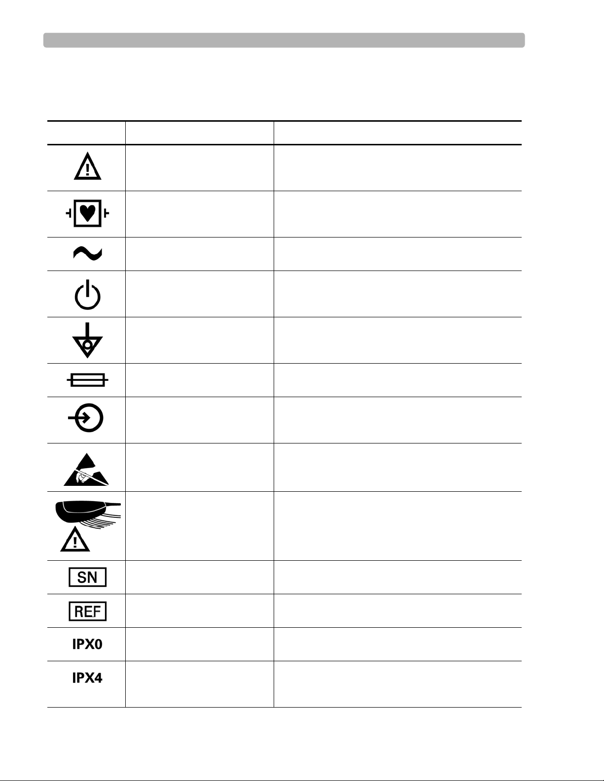
Safety Symbols Marked on the Cardiograph
Symbol Name Description
Attention See PageWriter Touch Instructions for Use for
Type CF ECG physio isolation is type CF, defibrillator proof.
Alternating current Indicates that the cardiograph is receiving alternating
Standby Pressing the button with this symbol on it puts the
information.
Suitable for all patient applications including direct
cardiac application. System is in continuous operation.
voltages.
cardiograph into Standby (power saving mode).
Equipotential grounding post Equipotential grounding po st used for establishing
Fuse Cardiograph contains a 1.5 amp (250V) time-delay
Input The connector near this symbol receives an incoming
Electrostatic Discharge Do not touch exposed pins. Touching exposed pins can
PIM (Patient Interface
Module), Attention
Serial Number The number next to this symbol is the serial number of
Product model number The number next to this symbol is the product model
common ground between instruments.
fuse.
signal.
cause electrostatic discharge which can damage the
cardiograph.
Attention, see PageWriter Touch Instructions for Use
for information on PIM RJ-11 receptacle.
the cardiograph.
number of the cardiograph
Entry of liquids Cardiograph has ordinary protection against the entry
of liquids.
Entry of liquids
The PIM (Patient Interface Module) is protected
against splashing water. Water splashed against the
PIM from any direction shall have no harmful effect.
PageWriter Touch Cardiograph Service Manual 1-3
Page 17
Introduction Safety Summary
Safety Symbols Marked on the Cardiograph
Symbol Name Description
Global Medical Device
Nomenclature Code
Global Medical Device Nomenclature Code is a 5-digit
code providing a brief description of the device, as
defined by EN ISO 15225.
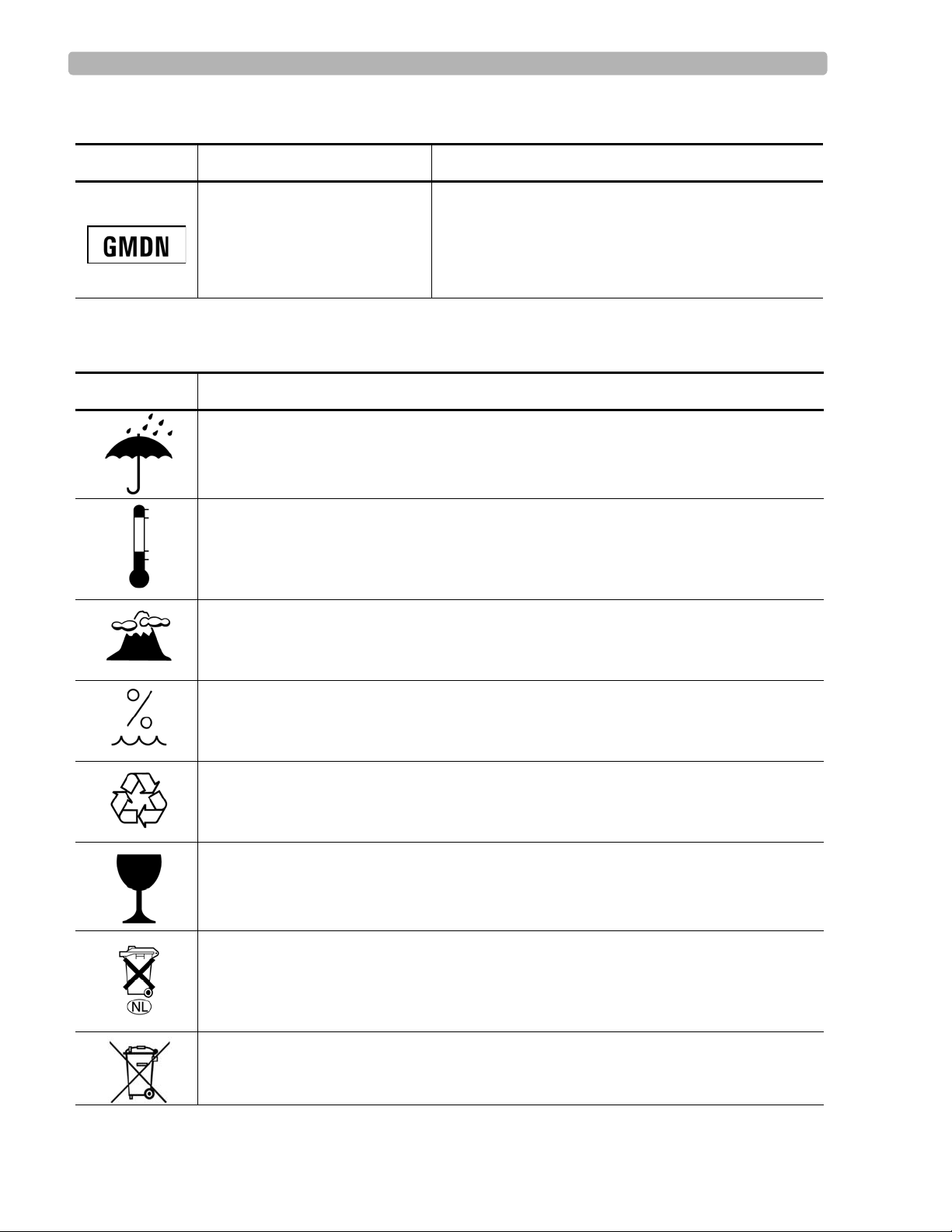
Safety Symbols Marked on the Cardiograph Packaging
Symbol Description
Keep dry.
o
Ambient temperature range of 15
transport and storage.
Atmospheric pressure range of 466 hPa to 1014 hPa for transport and storage.
C (59o F) to 35 oC (95o F) (non-condensing) for
Relative humidity range of 25% to 80% (non-condensing) for transport and storage.
Made from recycled materials.
Fragile.
Lithium ion battery. Do not dispose of in trash. Follow local regulations for disposing of
as small chemical waste.
This product consists of devices that may contain mercury, which must be recycled or
disposed of in accordance with local, state, or federal laws. (Within this system, the
backlight lamps in the monitor display contain mercury.)
1-4 PageWriter Touch Cardiograph Service Manual
Page 18

Introduction Important Patient and Safety Information
Safety Symbols Marked on the Cardiograph Packaging
Symbol Description
Dispose of in accordance with the requirements of your country.
Important Patient and Safety Information
The PageWriter Touch cardiograph isolates all connections to the patient from electrical
ground and all other conductive circuits in the cardiograph. This reduces the possibility of
hazardous currents passing from the cardiograph through the patient’s heart to ground.
WARNING Failure to follow these warnings could affect both patient and operator safety.
WARNING Do not connect the modem card to a phone line when the cardiograph is connected to a
patient.
WARNING Do not touch accessible connector pins and the patient simultaneously.
Electrical shock hazard. Keep cardiograph, Patient Interface Module (PIM) and all
cardiograph accessories away from liquids. Do not immerse the cardiograph, PIM, or
other accessories in any liquids.
WARNING When using additional peripheral equipment powered from an electrical source other
than the cardiograph, the combination is considered to be a medical system. It is the
responsibility of the operator to comply with IEC 60601-1-1 and test the medical system
according to the requirements. For additional information contact Philips Medical
Systems.
WARNING Do not use non-medical peripherals within 6 feet of a patient unless the non-medical
peripherals receive power from the cardiograph or from an isolation transformer that
meets medical safety standards.
WARNING The Welsh bulb electrodes (available as an accessory for the cardiograph) do not meet
the requirements of IEC 60601-2-25 for defibrillation recovery time, and cannot be
reliably used for patient diagnosis following defibrillation.
PageWriter Touch Cardiograph Service Manual 1-5
Page 19

Introduction Important Patient and Safety Information
When operating the cardiograph on AC power, ensure that the cardiograph and all other
electrical equipment connected to or near the patient are effectively grounded.
Use only grounded power cords (three-wire power cords with grounded plugs) and
grounded electrical outlets. Never adapt a grounded plug to fit an ungrounded outlet by
removing the ground prong or ground clip. If an un gro un ded plu g ad ap ter is r equired, use a
ground strap to connect the equipotential post (rear of the cardiograph, see page 1-13) to the
power source ground. Use the equipotential post when redundant earth ground is necessary
according to IEC 60601-1.
If a safe ground connection is not ensured, operate the cardiograph on battery power only.
The use of equipment that applies high frequency voltages to the patient (including
electrosurgical equipment and some respiration transducers) is not supported and may
produce undesired results.
Periodically inspect the patient data cable, lead wires, and AC power cord for any worn or
cracked insulation.
Keep the patient data cable away from power cords and any other electrical equipment.
Failure to do so can result in AC power line frequency interference on the ECG trace.
The Philips Medical Systems patient data cable (supplied with cardiograph) is an integral
part of the cardiograph safety features. Use of any other patient data cable may compromise
defibrillation protection and degrade cardiograph performance.
Only qualified personnel may service the cardiograph or may open the cardiograph housing
to access internal cardiograph components. Do not open any covers on the cardiograph.
There are no internal cardiograph components that are serviced by the operator.
Do not use this cardiograph near flammable anesthetics. It is not intended for use in
explosive environments or in operating rooms.
The use of the analog ECG output signal port (not supported on cardiograph, see page 1 -13)
should not be used when critical synchronization timing is required.
Do not touch the patient, patient data cable, or cardiograph during defibrillation. Death or
injury may occur from the electrical shock delivered by the defibrillator.
Ensure that the electrodes or lead wires do not come in contact with any other conductive
materials (including earth-grounded materials) especially when connecting or disconnecting
electrodes to or from a patient.
Connecting multiple cardiographs to the same patient may pose a safety hazard due to the
summation of leakage currents. Any combination of instruments should be evaluated by
local safety personnel before being put into service.
Do not pull on the paper while an ECG report is being printed. This can cause distortion of
the waveform and can lead to potential misdiagnosis.
Do not connect any equipment to the cardiograph RS-232 port that does not meet medical
safety requirements and that has not been evaluated by local safety personnel.
1-6 PageWriter Touch Cardiograph Service Manual
Page 20

Introduction Important Patient and Safety Information
Equipment connected to the cardiograph RS-232 port can cause ground leakage currents
exceeding the maximum specified in IEC 60601-1 safety standards.
Do not connect any equipment to the cardiograph RS-232 port if a patient is connected to
the cardiograph.
Only use the Philips Medical Systems AC power cord supplied with the cardiograph.
Periodically inspect the AC power cord and AC power connector (rear of cardiograph, see
page 1-13) to ensure that both are in a safe and operable condition. If the AC power cord or
AC power connector is not in a safe or operable condition, operate the cardiograph on
battery power and contact Philips Medical Systems for service.
The cardiograph has been safety tested with the recommended accessories, peripherals, and
leads, and no hazard was found when the cardiograph is operated with cardiac pacemakers
or other stimulators.
Do not connect any equipment or accessories to the cardiograph that are not approved by
Philips Medical Systems or that are not IEC 60601-1 approved. The operation or use of
non-approved equipment or accessories with the cardiograph is not tested or supported, and
cardiograph operation and safety are not guaranteed.
Only install Philips Medical Systems software on the cardiograph. The installation or use of
software not approved by Philips Medical Systems is strictly prohibited and cardiograph
safety and performance are not guaranteed.
Only use Philips Medical Systems replacement parts and supplies with the cardiograph. The
use of non-approved replacement parts and supplies with the cardiograph is strictly
prohibited. Cardiograph safety and performance are not guaranteed when non-approved
replacement parts and supplies are used with the cardiograph.
Manual measurements of ECG intervals and magnitudes should be performed on printed
ECG reports only. Do not make manual measurements of ECG intervals and magnitudes on
the touchscreen display since these ECG representations are scaled.
Only use patient electrodes that are approved by Philips Medical Systems. The use of non-
approved patient electrodes may degrade cardiograph perfo rmance.
The Philips Medical Systems warranty is applicable only if you use Philips Medical
Systems approved accessories and replacement parts. See “Supplies and Ordering
Information” on page 1-24 for more information.
For information on the standard IEC 60601-2-51, please go to the Philips InCenter web site
(
incenter.medical.philips.com). For information on using the Philips InCenter site, see page 1-
29.
Always put the cardiograph in Standby before replacing the Patient Interface Module
(PIM). Do not change the PIM while the cardiograph is in active use.
PageWriter Touch Cardiograph Service Manual 1-7
Page 21

Introduction The PageWriter Touch Cardiograph
The PageWriter Touch Cardiograph
This Philips product is intended to be used and operated only in accordance with the safety
procedures and operating instructions provided in this Instructions for Use, and for the
purposes for which it was designed. The purposes for which the product is intended are
provided below. However, nothing stated in this Instructions for Use reduces the
responsibility of the user for sound clinical judgment and best clinical procedures.
Intended Use
The intended use of the cardiograph is to acquire multi-channel ECG signals from adult and
pediatric patients from body surface ECG electrodes and to record, display, analyze, and store
these ECG signals for review by the user. The cardiograph is to be used in healthcare facilities
by trained healthcare professionals. Analysis of the ECG signals is accomplished with
algorithms that provide measurements, data presentations, graphical presentations, and
interpretations for review by the user.
The interpreted ECG with measurements and interpretive statements is offered to the clinician
on an advisory basis only. It is to be used in conjunction with the clinician's knowledge of the
patient, the results of the physical examination, the ECG tracings, and other clinical findings.
A qualified physician is asked to overread and validate (or change) the computer-generated
ECG interpretation.
Indications for Use
The cardiograph is to be used where the clinician decides to evaluate the electrocardiogram of
adult and pediatric patients as part of decisions regarding possible diagnosis, potential
treatment, effectiveness of treatment, or to rule out causes for symptoms.
The Philips 12-Lead Algorithm
The PageWriter Touch Cardiograph software uses the Philips 12-Lead Algorithm. The
algorithm in the software analyzes the morphology and rhythm on each of the 12 leads and
summarizes the results. The set of summarized measurements is then analyzed by the
clinically-proven ECG Analysis Program.
12-lead reports may include or exclude ECG measurements, reasons, or analysis statements.
Intended Use
The intended use of the Philips 12-Lead Algorithm is to analyze multi-channel ECG signals
from adult and pediatric patients with algorithms that provide measurements, data
presentations, graphical presentations, and interpretations for review by the user.
The interpreted ECG with measurements and interpretive statements is offered to the clinician
on an advisory basis only. It is to be used in conjunction with the clinician's knowledge of the
patient, the results of the physical examination, the ECG tracings, and other clinical findings.
A qualified physician is asked to overread and validate (or change) the computer-generated
ECG interpretation.
1-8 PageWriter Touch Cardiograph Service Manual
Page 22

Introduction Cardiograph Features
Indications for Use
The Philips 12-Lead Algorithm is to be used where the clinician decides to evaluate the
electrocardiogram of adult and pediatric patients as part of decisions regarding possible
diagnosis, potential treatment, effectiveness of treatment, or to rule out causes for symptoms.
Cardiograph Features
The PageWriter Touch cardiograph is one of the most advanced cardiographs. It offers touch
screen operation and numerous additional features making it ideal for high-volume
environments. The PageWriter Touch cardiograph is also well suited for hospitals requiring
speed and accuracy to process large volumes of ECGs daily.
The PageWriter Touch cardiograph consists of an electrocardiogr ap h with remote digital
patient module and an optional cart.
Features
The features of the PageWriter Touch cardiograph include:
Battery or AC operation
Remote digital acquisition module with replaceable patient leads with the capability for up
to 12 leads (software version B.01), or up to 16 leads (software ve rsion C.01.02 and
higher)
Three 15 and 16-lead options are available with software version C.01.02 and higher for
both adult and pediatric application
15-inch color liquid crystal touch screen display
Graphical representation of a human torso displaying leads that are loose or not connected
Data transmission between the cardiograph and a TraceMasterVue ECG Management
system in XML format via modem, LAN, WLAN, diskette, or optional PC (PCMCIA)
storage card, or USB memory stick
Software version C.01.02 and higher supports the export of ECG data in XML version
1.03, or XML version 1.04
Optional cart with convenient storage areas for supplies
Software version B.01, and C.01.02 and higher, support bidirectional orders download and
search capability with an OrderVue order handling system
Software version B.01, and C.01.02 and highe r, support algorithm version PH080A and
PH090A; algorithm version PH090A includes new enhancements and features including
heightened detection of atrial arrhythmia, the ability to suppress statements that indicate a
borderline or otherwise normal condition, lead reversal detection feature, ECG warning
statements when a life threatening cardiac event is detected, and the ability to print
Fridericia rate corrected QT interval and RR measurements on the ECG report
PageWriter Touch Cardiograph Service Manual 1-9
Page 23

Introduction PageWriter Touch Cardiograph Components
Time Sychronization feature that is used with a TraceMasterVue ECG Management
System (version B.01 and higher). Use of this feature helps to ensure the accuracy of the
displayed time on the cardiograph by regularly calibrating it with a configured
TraceMasterVue Remote Site
PageWriter Touch Cardiograph Components
The following sections illustrate the components and connection ports on the cardiograph and
the Patient Interface Module (PIM). Figures 1-1, 1-2, and 1-3 on the following pages show
front, side, and rear views of the PageWriter Touch cardiograph. For additional details, see the
PageWriter Touch Cardiograph Instructions for Use, Edition 7 on the User Documentation
CD.
1-10 PageWriter Touch Cardiograph Service Manual
Page 24
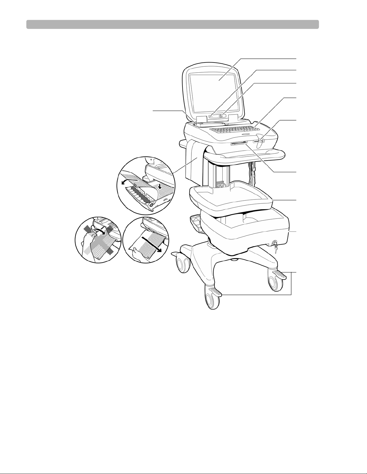
Introduction PageWriter Touch Cardiograph Components
A
B
D
E
F
H
I
J
G
C
K
Figure 1-1 Cardiograph and Cart (Front View)
A Patient Interface Module (PIM) G Magnetic card reader (optional)
B Printer/paper drawer H Diskette drive
C Touch screen I Storage shelf
D AC power on indicator light J Optional locking drawer
E On/Standby button K Wheel positioners
F Keyboard
PageWriter Touch Cardiograph Service Manual 1-11
Page 25
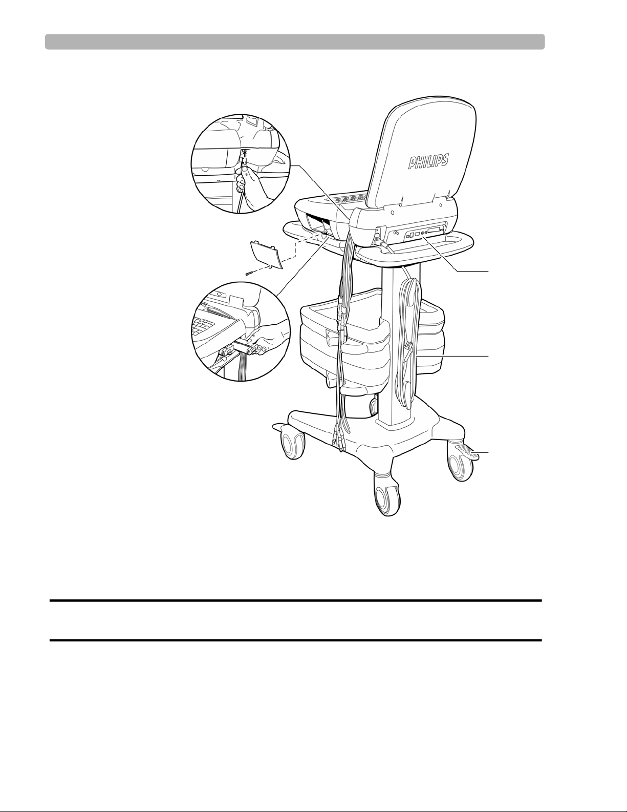
Introduction PageWriter Touch Cardiograph Components
M
N
Q
O
P
L
Figure 1-2 Cardiograph and Cart (Rear View)
L Patient Interface Module (PIM) connector O Wheel brake
M Battery compartment (Phillips head screw driver is
required to remove the battery door)
P AC power cord
N PIM leads Q Rear panel (see next page)
WARNING Do not connect the LAN cable connector to the PIM RJ-11 receptacle.
Do not plug a telephone connector into the PIM RJ-11 receptacle.
1-12 PageWriter Touch Cardiograph Service Manual
Page 26
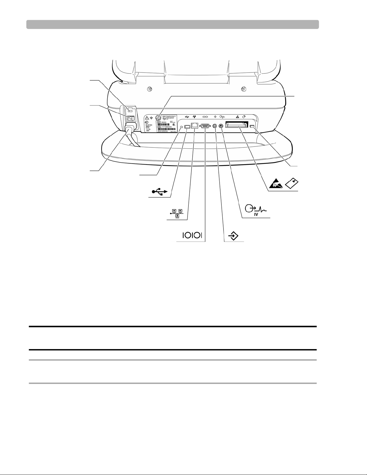
Introduction PageWriter Touch Cardiograph Components
I
H
G
F
E
D
C
B
A
J
K
L
Figure 1-3 Cardiograph Rear Panel
A Fuse door G Serial connector (not supported)
B AC power switch H Barcode scanner connector
C AC power cord I ECG out (not supported)
D Reset button J PC card slot
E USB memory stick connector K PC card eject button
WARNING Do not connect the modem card to a phone line when the cardiograph is connected to a
CAUTION Do not insert a USB memory stick into the cardiograph, or remove a USB memory from the
F LAN connector L Equipotential grounding post
patient.
cardiograph when the cardiograph is acquiring ECG data from a patient.
PageWriter Touch Cardiograph Service Manual 1-13
Page 27

Introduction PageWriter Touch Cardiograph Components
Thermal Printer
The cardiograph uses a thermal print head to record waveforms and label the ECG report. The
paper supplied with the cardiograph is a thermal paper designed to work with the print head.
The paper drawer accommodates both A and A4 size paper. A separate supplied paper shim is
required for A4 paper use.
Philips guarantees the performance of the cardiograph only when used with Philips supplies,
accessories, and paper that meets or exceeds Philips specifications.
Touch Screen Display
The cardiograph features a 15-inch touch screen color LCD display. Never touch the screen
with sharp objects or you may damage the touch screen surface.
Batteries
The PageWriter Touch is powered by two rechargeable Lithium Ion batteries (Philips part
number 989803129131). The cardiograph is intended to be operated primarily on battery
power. Proper care of the batteries will ensure a long life. For more details see the Care and
Maintenance chapter in the PageWriter Touch Cardiograph Instructions for Use, Edition 7,
included on this Service Documentation CD.
Patient Interface Module (PIM)
The Patient Interface Module (PIM) is a hand-held device that contains all of the
cardiograph’s waveform data acquisition electronics. The PIM connects to the patient data
cable and to the lead wires attached to the patient.The PIM is available in a standard 12-lead,
or an extended 16-lead model. The PIM has an Action button that is used to take ECG
Snapshots from the bedside.
The lead wires and the patient data cable are shipped fully connected to the PIM. For details
about connecting the lead wires to the PIM, see the PageWriter Touch Cardiograph
Instructions for Use, Edition 7.
1-14 PageWriter Touch Cardiograph Service Manual
Page 28
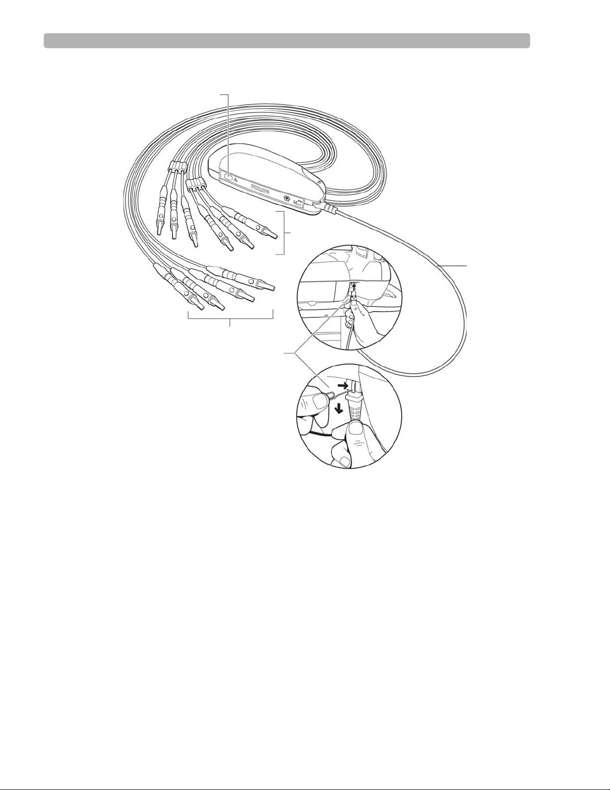
Introduction PageWriter Touch Cardiograph Components
A
B
C
D
D
Figure 1-4 Standard 12-Lead Patient Interface Module (PIM) Components
A Action button C Limb lead wires
B Chest lead wires D Patient data cable (connects to RJ-11 receptacle on right side
of cardiograph)
PageWriter Touch Cardiograph Service Manual 1-15
Page 29
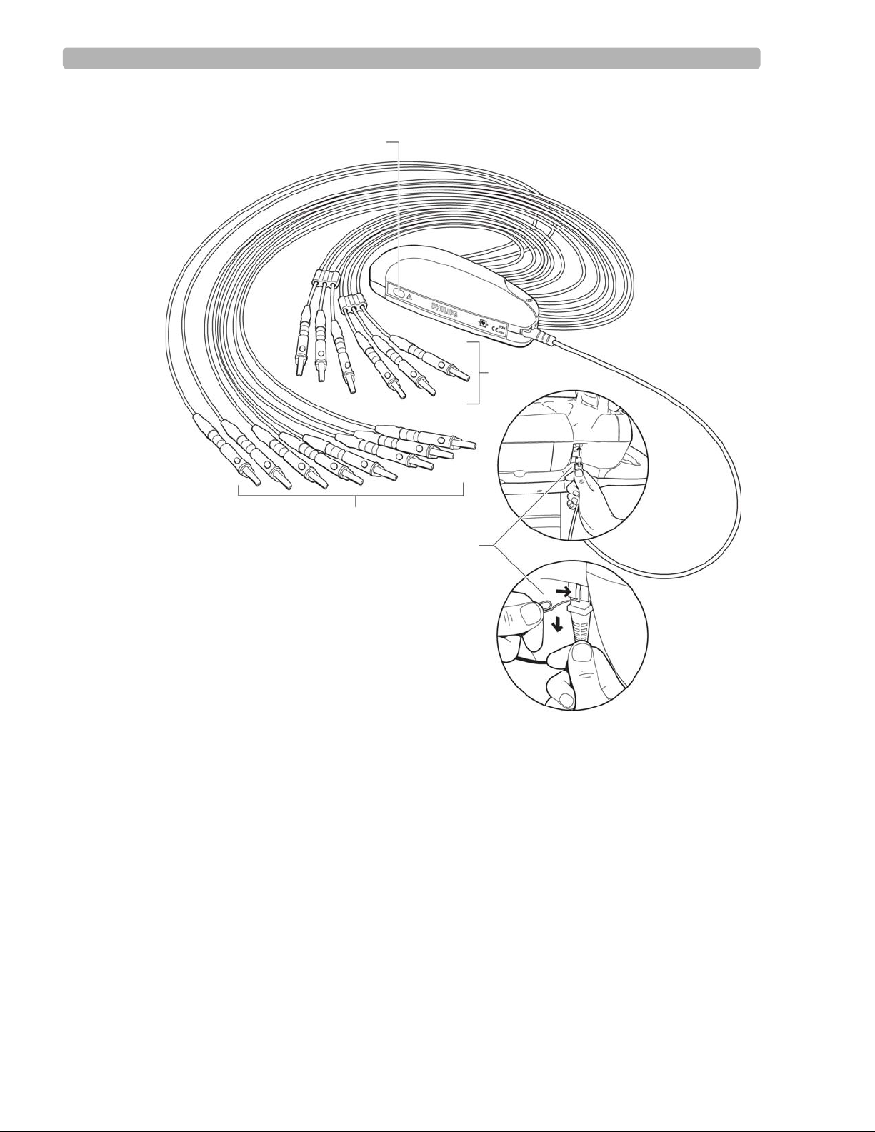
Introduction PageWriter Touch Cardiograph Components
A
B
C
D
D
Figure 1-5 16-Lead Patient Interface Module (PIM) Components
A Action button C Limb and optional extended lead wires
B Chest lead wires D Patient data cable (connects to RJ-11 receptacle on right side of
cardiograph)
Configuring the 16-Lead PIM
(software version C.01.02 and higher only)
The optional 16-lead PIM may be configured to support three different 15 and 16-lead options
for adult and pediatric application. The 16-lead PIM is shipped with the optional extended
leads connected to the PIM. The available 15 and 16-lead options are listed in Table 1-1, “15
and 16-Lead PIM Configuration Options,” on page 1-17.
1-16 PageWriter Touch Cardiograph Service Manual
Page 30
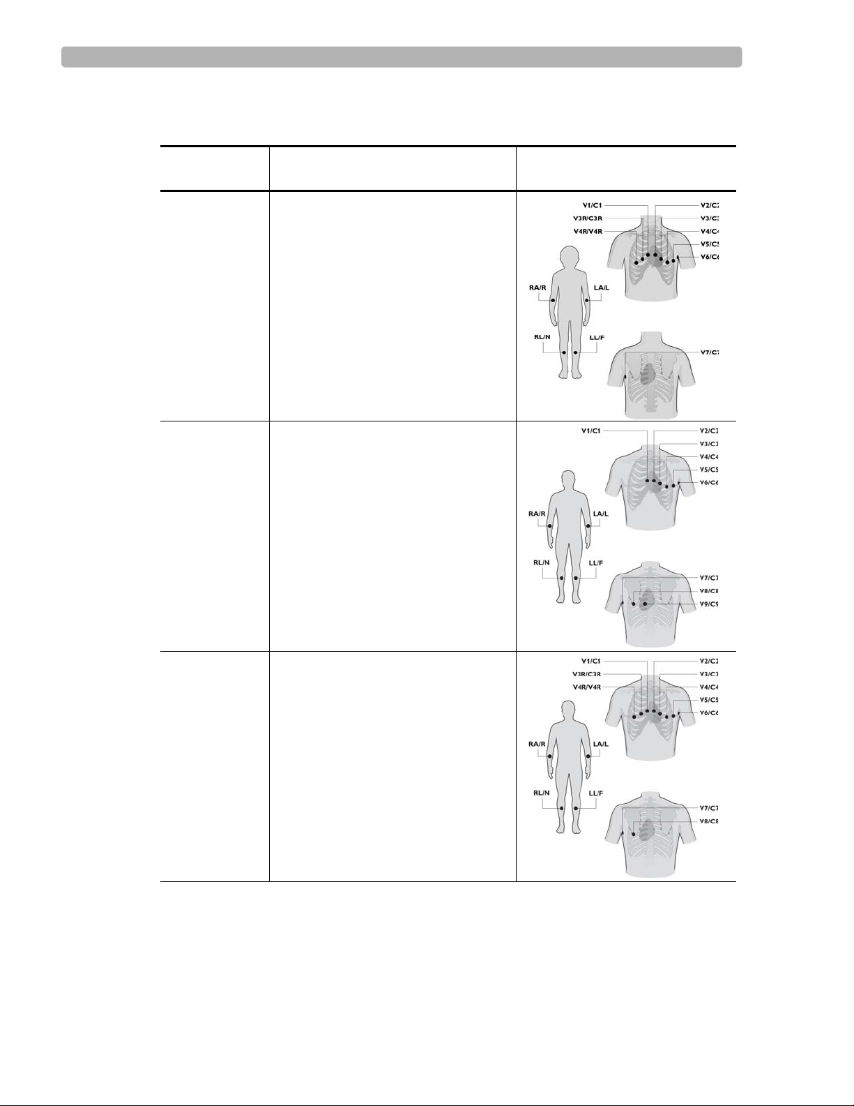
Introduction PageWriter Touch Cardiograph Components
Table 1-1 15 and 16-Lead PIM Configuration Options
Lead Option Standard 12-leads plus extended
leads (AAMI/IEC)
Pediatric
V3R (C3R), V4R (C4R), V7 (C7)
(15 leads)
Posterior
V7 (C7), V8 (C8), V9 (C9)
(15 leads)
Lead Placement
Balanced
(16 leads)
V3R (C3R), V4R (C4R), V7 (C7),
V8 (C8)
PageWriter Touch Cardiograph Service Manual 1-17
Page 31

Introduction PageWriter Touch Cardiograph Components
To configure the 16-lead PIM:
1
Press the On/Standby button to put the cardiograph into Standby.
CAUTION Always put the cardiograph in Standby before replacing the Patient Interface Module (PIM). Do
not change the PIM while the cardiograph is in active use.
2 Disconnect the PIM from the cardiograph, if necessary.
3 Remove the PIM cover by removing the screw on the cover housing (using a Phillips head
screwdriver).
1-18 PageWriter Touch Cardiograph Service Manual
Page 32

Introduction PageWriter Touch Cardiograph Components
4 The interior of the PIM is color coded and labeled to identify the lead connections. The
optional 16-lead connectors are labeled
A1-A4.
5 The slots A1-A4 may be configured as described in Table 1-2 to support the available 15
and 16-lead options. Insert the designated lead into the correct connector. If no lead is
inserted into a connector, insert the shorting plug (provided in the lead kit) into the
connector slot. Do not leave the connector empty.
Table 1-2 Configuring Optional 15 and 16-Lead PIM Options
Lead
Option
A1 A2 A3 A4
Pediatric V4R/C4R V3R/C3R V7/C7 Insert plug
(no lead inserted)
Posterior Insert plug
V9/C9 V7/C7 V8/C8
(no lead inserted)
Balanced V4R/C4R V3R/C3R V7/C7 V8/C8
NOTE To configure the 16-lead PIM for standard 12 leads, insert shorting plugs into slots A1-A4.
Figure 1-6 Shorting Plug (included in Lead Kit)
PageWriter Touch Cardiograph Service Manual 1-19
Page 33

Introduction PageWriter Touch Cardiograph Components
6 Attach the appropriate color-coded identification clip (included in the lead kit) to the lead.
7 Attach the small color clip (included in the lead kit) near the connector end of the lead
wire.
8 Ensure that each lead is firmly connected to the PIM.
9 Reattach the PIM cover.
Connecting the PIM to the Cardiograph
To connect the PIM to the cardiograph:
X Connect the patient data cable to the RJ-11 receptacle on the right side of the cardiograph.
1-20 PageWriter Touch Cardiograph Service Manual
Page 34

Introduction PageWriter Touch Cardiograph Components
WARNING To ensure safety and prevent damage to the system, ONLY connect the patient data
cable to the correct RJ-11 receptacle on the right side of the cardiograph.
WARNING Do not connect the patient data cable into the LAN port or into the optional modem
card connector.
CAUTION Always put the cardiograph in Standby before replacing the Patient Interface Module (PIM). Do not
change the PIM while the cardiograph is in active use.
Placing the PIM in the Cardiograph Cradle
Ensure that the PIM is properly inserted into the PIM cradle on the front of the cardiograph
with the lead wires facing down and the Action button facing up. Do not lower the touch
screen if the lead wires are facing up. The touch screen may be damaged.
To place the PIM in the cradle:
X Place the PIM in the cradle with the lead wires facing down and the Action button facing
up.
Figure 1-7 Placing the PIM in the cardiograph cradle
CAUTION Do not place the PIM in the cradle with the lead wires facing up.
PageWriter Touch Cardiograph Service Manual 1-21
Page 35

Introduction Installation
Installation
The PageWriter Touch does not require installation by Philips field personnel. The
cardiograph is customer-installable. See Chapters 2 and 3 of the PageWriter Touch
Cardiograph Instructions for Use, Edition 7, that is included on this Service Documentation
CD, for information on cardiograph configuration.
Options and Accessories
The country and region option includes the appropriate keyboard, power cord, printer paper,
patient leads, and language. The following table shows the configuration for the country and
region.
Table 1-1 Power Cord Part Numbers
Power Cord
Key
900 453563466251 (M5000-61620)
901 453563466261 (M5000-61621)
902 453563466271 (M5000-61622)
903 453563466281 (M5000-61623)
917 453563466301 (M5000-61625)
918 453563466311 (M5000-61626)
920 453563466321 (M5000-61627)
921 453563466331 (M5000-61628)
Table 1-2 Options
Option Description
A01 PageWriter Touch Cardiograph and Cart System
A02 PageWriter Touch Cardiograph only
Philips Part Number (CMS P/N)
C01 Barcode Reader
C02 Magnetic Card Reader
C03 PCMCIA card ECG storage
C10 Modem Card - U.S. and Canada only
D01 Release C software
D16 16-Lead PIM (requires version C.01.02 and higher software)
1-22 PageWriter Touch Cardiograph Service Manual
Page 36

Introduction Upgrades
Standard Accessories
The standard accessories are based on model number and localization (see “Localization
Options” on page 1-28). Accessories include:
200 sheets of z-fold paper
– English paper p/n M2481A
– Metric paper p/n M2483A
Tab electrodes p/n 139433
Alligator clips
– 989803129231 (AAMI)
– 989803129241 (IEC)
PageWriter Touch Cardiograph User Documentation CD
PageWriter Touch Cardiograph Interactive Training Program
Upgrades
Upgrades are available to add specific functionality to cardiographs in the field. These
upgrades currently include
Part Number Description
989803127311 Barcode Reader
989803127321 Magnetic Card Reader
989803127331 PC Card (256 MB storage)
989803127341 Fax Transmission Software
989803142041 Wireless LAN Card
989803127381 PageWr iter Touch Cardiograph Interactive Training Program
CD (additional copies)
989803127391 PageWriter Touch Cardiograph Service Documentation CD
989803127401 PageWriter Touch Cardiograph User Documentation CD
(additional copies)
989803127411 Patient Interface Module (PIM) (AAMI)
989803127421 Patient Interface Module (PIM) (IEC)
989803127431 PageWriter Touch Cardiograph Cart
989803127441 PageWriter Touch Cardiograph Cart Optional Locking Drawer
989803127451 PageWriter Touch Cardiograph Cart Additional Shelf
989803149161 Modem Card (USA and Canada only)
PageWriter Touch Cardiograph Service Manual 1-23
Page 37

Introduction Supplies and Ordering Information
Part Number Description
989803127471 LAN Cable (2.13 m/7.0 ft.)
For more information on available upgrades, consult with your sales representative, dealer, or
distributor.
Supplies and Ordering Information
The part numbers for all supplies for the PageWriter Touch cardiograph are listed in this
section.
NOTE This section describes supply part numbers only. For repair part numbers, see Chapter 7,
“Replacement Parts”
Ordering Supplies
All supplies may be ordered on the web at:
http://shop.medical.philips.com
Use the part numbers listed below for reference to ensure that the correct supplies are ordered.
1-24 PageWriter Touch Cardiograph Service Manual
Page 38

Introduction Supplies and Ordering Information
Special Note about Welsh Bulb Electrodes
Figure 1-8 Welsh Bulb Electrode
Welsh Bulb electrodes are offered as an optional supply part with the PageWriter Touch
cardiograph. Special care is necessary when using these electrodes. Pay special attention to all
warnings associated with these electrodes. For information on cleaning the reusable Welsh
Bulb electrodes, see Chapter 10 “Care and Maintenance” of the PageWriter Touch
Cardiograph Instructions for Use, Edition 7. Philips Medical Systems recommends the use of
disposable electrodes with the PageWriter Touch cardiograph.
WARNING\ The Welsh bulb electrodes (available as an accessory for the cardiograph) do not meet
the requirements of IEC 60601-2-25 for defibrillation recovery time, and cannot be
reliably used for patient diagnosis following defibrillation.
WARNING Always clean and disinfect reusable electrodes before patient use. See Chapter 10 “Care
and Maintenance” of the PageWriter Touch Cardiograph Instructions for Use for
information on cleaning and disinfecting reusable electrodes. Failure to properly clean
and disinfect reusable electrodes before patient use may cause infectious materials to be
transferred between patients.
CAUTION The Welsh bulb electrodes contain natural rubber latex which may cause allergic reactions.
PageWriter Touch Cardiograph Service Manual 1-25
Page 39

Introduction Supplies and Ordering Information
PageWriter Touch Cardiograph Supply Part Numbers
PIM Patient Data Cables
Part Number Description
989803145401 USB Patient Data Cable
Complete Lead Sets
Part Number Description
989803129161 Complete AAMI Lead Set for Standard 12 Leads
989803129191 Complete IEC Lead Set for Standard 12 Leads
989803129221 Long Complete IEC Lead Set for Standard 12 Leads
989803148931 Complete AAMI Lead Set for 16 Leads
989803149181 Complete IEC Lead Set for 16 Leads
989803149191 Long Complete IEC Lead Set for 16 Leads
989803148881 16 Lead Spare Part Kit (includes color lead clips for both AAMI and IEC,
banana post adapters, lead separators, and PIM shorting plugs)
Replacement Lead Sets and Accessories
Part Number Description
989803129141 AAMI Limb Lead Set, 99 cm/39 in
989803129151 AAMI Chest Lead Set, 61 cm/24 in
989803129171 IEC Limb Lead Set, 99 cm/39 in
989803129181 IEC Chest Lead Set, 61 cm/24 in
989803129201 IEC Long Limb Lead Set, 137 cm/54 in
989803129211 IEC Long Chest Lead Set, 99 cm/39 in
989803129231 Alligator Clips for Disposable Tab Electrodes (AAMI) (10 total per pack)
989803129241 Alligator Clips for Disposable Tab Electrodes (IEC)
(10 total per pack)
989803101361 Alligator Clip Extender for Disposable T ab Electrodes (10 total per pack)
(AAMI)
989803101371 Alligator Clip Extender for Disposable Tab Electrodes (10 total in pack)
(IEC)
989803106061 Wide Disposable Tab Electrode Connector
(10 total per pack) (AAMI/IEC)
1-26 PageWriter Touch Cardiograph Service Manual
Page 40

Introduction Supplies and Ordering Information
Replacement Lead Sets and Accessories (continued)
Part Number Description
989803101691 Adult Limb Clamp Electrode (4 total in pack)
(AAMI/IEC)
Electrodes
Part Number Description
989803100441 Disposable cardiography electrode, resting diagnostic ECG
989803106051 Disposable electrode, adult, resting ECG
(not available in Japan)
989803149901 Pediatric disposable tab electrode
989803101311 15 mm diameter Welsh Bulb Electrode (AAMI)
989803101651 15 mm diameter Welsh Bulb Electrode (IEC) with banana plug adapter
Printer Paper
Part Number Description
989803106261 Z-fold, with header, A size (8.5 x 11 in/21.6 x 28 cm)
989803106271 Z-fold, with header, A4 size (8.27 x 11.69 in/21 x 29.69 cm)
989803106281 Anti-fade, A size (8.5 x 11 in/21.6 x 28 cm)
989803106291 Anti-fade, A4 size (8.27 x 11.69 in/21 x 29.69 cm)
Batteries
Part Number Description
989803129131 Lithium-ion replacement batteries
(2 battery packs are required to power the cardiograph)
PageWriter Touch Cardiograph Service Manual 1-27
Page 41

Introduction Other Resources
Localization Options
The following table shows the Philips Medical Systems option number and associated
languages/components.
Table 1-3 Localization Options
Option Country
ABA USA/
Labels
& User
Doc.
Interp.
Rpt
Keyboard
PIM/Lead
Version
English English US English AAMI 903
Power
Cord
Opt.
*
Default
Paper
Locale
AUS
Canada
(English)
ABU UK English English British IEC 900* A4 English
(UK)
ABG Australia English English US English AAMI 901 A4 English
(Australian)
ABB European
English
AKJ Israel &
Gaza Strip
AB4 Singapore
& Hong
Kong
English English British IEC 902 A4 English
(UK)
English English US English IEC M5000-
61629
A4 English
(Israel)
English English British AAMI 900 A4 English
(Singapore
& Hong
Kong)
* See Table 1-1, “Power Cord Part Numbers,” on page 1-22
Other Resources
For additional information on the PageWriter Touch cardiograph, see:
PageWriter Touch User Documentation CD
PageWriter Touch Cardiograph Interactive Training Program
PageWriter Touch Service Training
PageWriter Touch Wireless LAN Installation Instructions
1-28 PageWriter Touch Cardiograph Service Manual
Page 42

Introduction Philips 12-Lead ECG XML Information and Tools
Philips 12-Lead ECG XML Information and Tools
The PageWriter Touch cardiograph exports ECG data in XML (Extensible Markup Language)
format. For software version C.01.02 and higher, there are two available XML schema
versions on the cardiograph, version 1.03 and version 1.04. Versio n 1 .03 ex po rts ECG data in
12-lead format only, and version 1.04 exports ECG data for up to 16 leads.
The Philips 12-lead XML Utilities are only compatible with ECG data exported in 12-lead
format using XML version 1.03. The Philips 12-lead XML Utilities are not compatible with
16-lead ECG data exported using XML schema version 1.04. To transmit 16-lead ECG files to
the XML Utilities, XML version 1.03 must be selected as the default XML version for the
cardiograph. Using XML version 1.03, 16-lead ECGs are then downsampled as standard 12lead ECGs when transmitted to the XML Utilities (ECG data from the extended leads is
deleted, and only ECG data from the standard 12-leads is transmitted). For more information
on specifying a default XML version on the cardiograph, see "About XML Versions" on
page 8-8 of the PageWriter Touch Cardiograph Instructions for Use, Edition 7.
NOTE The default XML version setting on the cardiograph must be coordinated with the XML version
compatibility of a TraceMasterVue ECG Management System used by your facility.
Downloading the XML Utilities and the XML Utility Suite
Instructions for Use
The XML schema for the Philips 12-Lead ECG files, along with a complementary suite of
XML utilities and tools, are available for download from the Philips InCenter web site
(
incenter.medical.philips.com). An XML Utility Suite Instructions for Use is also available for
download. This Instructions for Use describes how to install and configure the XML utilities.
Check the InCenter site regularly for further information and updates to the XML Utility
Suite.
Using the Philips InCenter Site
The Philips InCenter site provides frequent updates to all Philips Cardiac Systems product
documentation and product software, including the PageWriter Touch cardiograph.
The Philips InCenter site requires an active registration and password. To register, go to the
InCenter site at:
On the following E Support page, click the
documentation for cardiology products
Cardiac Systems InCenter Registration page appears. Complete all of the information fields on
the page to receive a login and password for the InCenter site.
Registration for the InCenter site requires the serial number(s) for all PageWriter Touch
cardiographs in active use at your facility. The serial number is found on the product
identification label. The product identification label is located on the rear panel of the
cardiograph as shown in Figure 1-9.
incenter.medical.philips.com and click on the Need help? link on the main page.
link located on the right side of the page. The
Click here for access to software updates and
PageWriter Touch Cardiograph Service Manual 1-29
Page 43

Introduction Using the Philips InCenter Site
A
Figure 1-9 Serial Number on Product Identification Label
A Product Serial Number
About Adobe Acrobat Versions
Adobe Acrobat Reader version 8.0 must be installed on the PC that is used to access the
Philips InCenter site. Previous versions of Acrobat Reader are not compatible with the Philips
InCenter site, and attempting to access InCenter with a previous version of Acrobat Reader
will result in error messages when opening documents. Uninstall all previous versions of
Acrobat Reader, and then proceed for a free install of Acrobat Reader 8.0 at:
Any version of Adobe Acrobat Professional or Acrobat Elements are also not compatible with
the Philips InCenter site, and error messages will appear when opening documents with these
applications. Acrobat Reader 8.0 must be installed in addition to Acrobat Professional or
Acrobat Elements.
Follow this procedure when accessing documents on the Philips InCenter site.
To access documents on the Philips InCenter site:
Exit Acrobat Professional or Acrobat Elements (if open).
1
2 Start Acrobat Reader 8.0.
3 Open Internet Explorer, and go to the Philips InCenter site. Keep Acrobat Reader 8.0 open
the entire time while accessing the InCenter site.
www.adobe.com.
1-30 PageWriter Touch Cardiograph Service Manual
Page 44

Introduction Contacting a Philips Response Center
Downloading Documentation at the Philips Website
Documentation for many Philips medical products can be downloaded from the Philips
website, at
www.medical.philips.com/goto/productdocumentation.
Contacting a Philips Response Center
The Philips Response Center can assist with product troubleshooting and provide technical
expertise to help with any issue with the PageWriter Touch cardiograph or any of its
accessories.
For more information on the Philips Response Center go to:
www.medical.philips.com/main/services/response_center
North America Response Centers
Country Telephone Number
Canada (800) 323 2280
Mexico 01 800 710 8128
Puerto Rico 1 787 754 6811
United States (800) 722 9377
South America Response Centers
Country Telephone Number
Argentina 54 11 4546 7698
Brazil 0800 701 7789
Chile 0800 22 3003
Columbia 01 8000 11 10 10
Peru 51 1 620 6440
Europe Response Centers
Country Telephone Number
United Kingdom 44 0870 532 9741
Fax: 44 01737 23 0550
Austria 43 1 60101 820
Belgium 32 2 525 7102 (French)
32 2 525 7103 (Flemish)
PageWriter Touch Cardiograph Service Manual 1-31
Page 45

Introduction Contacting a Philips Response Center
Europe Response Centers (continued)
Country Telephone Number
Czech Republic
31 40 2781619
MCR Response Center
(located in The
Netherlands)
Denmark 45 80 30 30 35
Finland 358 615 80 400
France 0 810 835 624
Germany 0180 5 47 5000
Greece
31 40 2781619
MCR Response Center
(located in The
Netherlands)
Hungary
31 40 2781619
MCR Response Center
(located in The
Netherlands)
Italy 0800 232100
Netherlands 31 40 27 211 27
Norway 47 800 84 080
Poland
31 40 2781619
MCR Response Center
(located in The
Netherlands)
Rumania
31 40 2781619
MCR Response Center
(located in The
Netherlands)
Russia
31 40 2781619
MCR Response Center
(located in The
Netherlands)
Slovak Republic
31 40 2781619
MCR Response Center
(located in The
Netherlands)
1-32 PageWriter Touch Cardiograph Service Manual
Page 46

Introduction Contacting a Philips Response Center
Europe Response Centers (continued)
Country Telephone Number
Spain 34 90 230 4050
Sweden 46 200 81 00 10
Switzerland 0800 80 3000 (German)
0800 80 3001 (French)
Asia Response Centers
Country Telephone Number
Australia 1800 251 400
China 800 810 0038
Hong Kong 852 2876 7578
India 1600 112 444
Indonesia 62 21 7910040, ext 8610
Japan 81 (0)120 095 205
Korea 82 (0)2 3445 9010
Malaysia 18 00 886 188
New Zealand 0800 251 400
Philippines 63 2 8162617 ext. 875
Singapore 1800 Philips
Taiwan 0800 005 616
Thailand 66 (0)2 614 3569
Africa and Middle East
Country Telephone Number
All countries
MCR Response Center
(located in The Netherlands)
31 40 2781619
PageWriter Touch Cardiograph Service Manual 1-33
Page 47

Chapter 2Theory of Operation
This chapter includes the following information:
System Overview. . . . . . . . . . . . . . . . . . . . . . . . . . . . . . . . . . . . . . . . . . . . 2-2
Hardware Logical View . . . . . . . . . . . . . . . . . . . . . . . . . . . . . . . . . . . . . . . 2-2
Main Control Board . . . . . . . . . . . . . . . . . . . . . . . . . . . . . . . . . . . . . . 2-2
Display and Touch Screen . . . . . . . . . . . . . . . . . . . . . . . . . . . . . . . . . 2-3
Patient Information Module (PIM). . . . . . . . . . . . . . . . . . . . . . . . . . . 2-4
Printer Control (USB). . . . . . . . . . . . . . . . . . . . . . . . . . . . . . . . . . . . . 2-4
Diskette Drive (USB) . . . . . . . . . . . . . . . . . . . . . . . . . . . . . . . . . . . . . 2-4
USB External Drive . . . . . . . . . . . . . . . . . . . . . . . . . . . . . . . . . . . . . . 2-4
Smart Batteries (SMB) . . . . . . . . . . . . . . . . . . . . . . . . . . . . . . . . . . . . 2-4
Keyboard (PS/2) . . . . . . . . . . . . . . . . . . . . . . . . . . . . . . . . . . . . . . . . . 2-4
Magnetic Card Reader (Serial). . . . . . . . . . . . . . . . . . . . . . . . . . . . . . 2-4
Barcode Reader (PS/2) . . . . . . . . . . . . . . . . . . . . . . . . . . . . . . . . . . . . 2-5
Top Level ECG Data Flow and Storage . . . . . . . . . . . . . . . . . . . . . . . . . . 2-5
About XML Versions for Software Version C.01.02 and higher . . . . 2-6
Internal Main Archive. . . . . . . . . . . . . . . . . . . . . . . . . . . . . . . . . . . . . 2-8
Internal Remote Archive. . . . . . . . . . . . . . . . . . . . . . . . . . . . . . . . . . . 2-8
External PC Card or USB Memory Stick Archives . . . . . . . . . . . . . . 2-8
USB Memory Stick. . . . . . . . . . . . . . . . . . . . . . . . . . . . . . . . . . . . . . . 2-8
External Diskette Archives. . . . . . . . . . . . . . . . . . . . . . . . . . . . . . . . . 2-9
Rendered ECG Report Prints . . . . . . . . . . . . . . . . . . . . . . . . . . . . . . . 2-9
Fax-Rendered ECG Report Print . . . . . . . . . . . . . . . . . . . . . . . . . . . 2-10
Power System Overview. . . . . . . . . . . . . . . . . . . . . . . . . . . . . . . . . . . . . 2-11
Batteries . . . . . . . . . . . . . . . . . . . . . . . . . . . . . . . . . . . . . . . . . . . . . . 2-12
SMBus Smart System. . . . . . . . . . . . . . . . . . . . . . . . . . . . . . . . . . . . 2-14
Power Labels. . . . . . . . . . . . . . . . . . . . . . . . . . . . . . . . . . . . . . . . . . . 2-14
Power Management. . . . . . . . . . . . . . . . . . . . . . . . . . . . . . . . . . . . . . . . . 2-16
Battery Charging Logic . . . . . . . . . . . . . . . . . . . . . . . . . . . . . . . . . . 2-16
Battery Fuel Gauge. . . . . . . . . . . . . . . . . . . . . . . . . . . . . . . . . . . . . . 2-16
Battery Discharging . . . . . . . . . . . . . . . . . . . . . . . . . . . . . . . . . . . . . 2-18
Battery Charging. . . . . . . . . . . . . . . . . . . . . . . . . . . . . . . . . . . . . . . . 2-18
Charge Current . . . . . . . . . . . . . . . . . . . . . . . . . . . . . . . . . . . . . . . . . 2-18
Current Consumption in QuickStart and Standby Mode . . . . . . . . . 2-18
Battery Calibration . . . . . . . . . . . . . . . . . . . . . . . . . . . . . . . . . . . . . . 2-18
Battery Information. . . . . . . . . . . . . . . . . . . . . . . . . . . . . . . . . . . . . . 2-19
2
2-1
Page 48

Theory of Operation System Overview
System Overview
The PageWriter Touch cardiograph system performs acquisition, analysis, presentation,
printing, storage, and transfer of ECG waveforms and other patient clinical data.
The PageWriter Touch cardiograph consists of three major subsystems:
Main controller
A single-board computer (SBC) with extensive I/O facilities, running Windows CE 3.0.
The PageWriter Touch application software runs on the main controller, which includes
the display and user-input subsystems.
Print controller
A controller board which provides all the real-time management of the printer. The print
controller communicates with the main controller through USB.
Patient Input Module (PIM)
A controller running Windo ws CE 3.0, coup led with a sig nal acquisition board employi ng
Philips proprietary mixed-signal ASIC technology for ECG acquisition. The PIM
communicates with the main controller through USB.
Hardware Logical View
Control of the PageWriter Touch cardiograph is provided by application software running on
the main control board, interacting with numerous hardware and software subsystems. The
following are high-level descriptions of these various subsystems.
Main Control Board
The main control SBC contains loader software and the Windows CE kernel image in its
internal flash memory (32 MB). At system boot, a system RAM test is performed by the loader
(onboard RAM is 64 MB), and then the Windows CE kernel loads. When CE loads, the
application launcher runs, verifying system and executable images before loading the
SierraGUI application. All interaction with the operator is through the SierraGUI application.
The application software, as well as all ECG archives, are stored on a separate 128 MB or
higher CompactFlash (CF) card installed in the main control board.
The following illustration provides an overview of the device and interfaces provided by the
main control board.
2-2 PageWriter Touch Cardiograph Service Manual
Page 49

Hardware Logical View Theory of Operation
Figure 2-1 Devices and Interfaces for Main Control Board
The board presents a backplane through the rear of the PageWriter Touch case, allowing the
user to access interfaces labeled as external in Figure 2-1, along with the PCMCIA slot, and
the PS/2 connection for a barcode reader device.
Display and Touch Screen
The cardiograph display comprises an XGA-compatible, full-color LCD display with
backlight and overlaid touch screen. It is driven by the main control board using a graphics
accelerator chip and dedicated touch screen support hardware. The touch screen provides
finger-tap input substituting for the normal Win32 mouse-click input.
PageWriter Touch Cardiograph Service Manual 2-3
Page 50

Theory of Operation Hardware Logical View
Patient Information Module (PIM)
The PIM is an SA1110-based WinCE subsystem, which is connected by USB to the main
control board. It provides real-time data acquisition of ECG signal from an electrode
connected patient.
Printer Control (USB)
The printer control board is a processor-based control board for the PageWriter Touch thermal
printer mechanism. The board is connected by USB to the main control board and is powered
by the power circuit of the main control board. It provides ECG waveform rendering and basic
bitmap imaging operations, and uses a PCL-like control lan guage API for page description an d
feed control. It controls the print head, motor, and detects drawer-open and top-of-form.
Diskette Drive (USB)
The cardiograph has a USB 3.5” diskette drive, which provides DOS HD 3.5 diskette readand-write access. It works with the supplied WinCE2.0 driver USBFDD.DLL.
USB External Drive
The cardiograph has an external USB drive accessed from the rear panel of the cardiograph.
The USB drive is used with the optional USB memory stick.
Smart Batteries (SMB)
The cardiograph uses twin 10.8V lithium ion batteries, which provide industry-standard SMB
power management and communications support. Chargi ng and switching of batteries is
dictated by the main control board.
Keyboard (PS/2)
The cardiograph includes a laptop-format, PS/2, sealed, full key action keyboard. It includes a
keyboard matrix and daughter board, which provides language-specific keyboard support and
decoding via PS/2 and standard WinCE device drivers for key input into the PageWriter
Touch cardiograph and is powered by PS/2 connection.
Magnetic Card Reader (Serial)
Also available is a magnetic card strip reader, which provides ISO and standard encoded
magnetic strip support via RS-232 serial internal connection to main control board. Manual
removal and insertion is required.
2-4 PageWriter Touch Cardiograph Service Manual
Page 51

Top Level ECG Data Flow and Storage Theory of Operation
Barcode Reader (PS/2)
Also available is a keyboard-emulating barcode scanner and reader, which connects through
an external PS/2 connector and provides standard barcode scanning capability. It emulates a
keyboard, allowing scanned codes to be presented to the PageWriter Touch cardiograph as if
they had been typed on the standard keyboard, po wered by a PS/2 conn ectio n. The barcod e
reader can be configured using special barcodes.
Top Level ECG Data Flow and Storage
A general ECG workflow begins with the acquisition of ECG data by the Patient Interface
Module (PIM) from electrodes placed on a patient. Data is streamed real-time to the main
control board, where it is received into the application buffers in RAM. These buffers are used
to present the signal data on the real-time screen. When the user initiates an Auto ECG report
print, presses the Action button on the PIM, or the Snapshot button on the display, or is using
the Timed ECG acquisition, corresponding 10-second segments of the signal data are then
copied to the temporary ECG storage memory in RAM.
These 10-second segments are named ECG reports that can be previewed and printed. In the
case of Auto mode, the ECG report may automatically print without any user intervention. An
ECG report contains signal data, analysis information, patient demographics, and acquisition
information, along with operator and device information. See the PageWriter Touch XML
schema for a complete description of the contents of the ECG data record. The XML schema
is available as a part of the XML utilities and may be downloaded from the Philips InCenter
site. For information on using the InCenter site, see “Using the Philips InCenter Site” on
page 1-30.
If the
Auto Save When Print option is enabled, or the user selects Save button on the Index
screen, the ECG report is saved in the XML format to the internal Main Archive. For software
version C.01.02 and higher, the XML version that ECG data is saved may be specified as
XML version 1.03, or version 1.04. This archive is non-volatile and resides on the internal
CompactFlash (CF) card. Index files with a
From the internal Main Archive, the ECG XML data format files can be copied, deleted,
previewed, printed, and transferred to other devices. The internal Main Archive cann ot receive
ECG XML files from non-Philips external devices. Retrieved ECG file storage is limited to
the internal Remote Archive.
NOTE PageWriter Touch-generated ECG XML files comply with the Philips Medical Systems ECG XML
Schema version. They incorporate an embedded CRC32 value, which is used to ensure the data
integrity of the file.
.cdb extension are also maintained in this archive.
PageWriter Touch Cardiograph Service Manual 2-5
Page 52

Theory of Operation Top Level ECG Data Flow and Storage
About XML Versions for Software Version C.01.02 and
higher
For software version C.01.02 and higher, the cardiograph can be configured to transmit ECG
data in XML version 1.03 or in version 1.04. The XML version selected is determined by the
software revision level of the TraceMasterVue ECG Management System to which the ECG
data is transferred.
XML version 1.03 is compatible with the TraceMasterVue ECG Management System
software version A.02. This XML version does not support the transmission of ECG data in
any extended 15 or 16-lead format. If a 15 or 16-lead ECG is transferred using this XML
version, the additional ECG data for the right side precordial or posterior leads is deleted, and
the ECG is transferred in standard 12-lead format.
XML version 1.04 is compatible with the TraceMasterVue ECG Management System
software version B.01 or higher. Full ECG data from extended lead 15 or 16-lead ECGs is
transferred to the TraceMasterVue ECG Management System.
NOTE Only XML version 1.03 is compatible with the Philips 12-Lead XML Utilities. For more information on
the Philips 12-Lead XML Utilities, see “Downloading the XML Utilities and the XML Utility Suite
Instructions for Use” on page 1-30.
2-6 PageWriter Touch Cardiograph Service Manual
Page 53

Top Level ECG Data Flow and Storage Theory of Operation
Figure 2-2 ECG Flow and Storage
PageWriter Touch Cardiograph Service Manual 2-7
Page 54

Theory of Operation Top Level ECG Data Flow and Storage
Internal Main Archive
The internal Main Archive resides on the internal CompactFlash (CF) card, and is used as the
primary ECG data repository. ECG XML files and related index files are stored here in the
SierraArchiveInternal directory. For software version C.01.02 and higher, the XML files are
stored in the specified XML version 1.03 or 1.04. All stored ECG files transition through this
archive prior to transfer or copying to other devices, such as a PC card, USB memory stick, or
TraceMasterVue.
Currently, the internal Main Archive is limited to a maximum of 150 ECGs when combined
with the internal Remote Archive. The Remote Site Archive contains ECGs downloaded from
a specified TraceMasterVue ECG Management System. For example, 50 ECGs stored in the
internal Main Archive, and 50 ECGs stored in the internal Remote Archive result in a
remaining available storage of 50 ECGs. These can then be saved in either the internal Main or
Remote archives.
Internal Remote Archive
The internal Remote Archive resides on the internal CompactFlash (CF) card in the same
manner as the internal Main Archive. All XML files retrieved from remote sites, such as the
TraceMasterVue ECG Management system, reside in this archive until deleted. ECG XML
files and related index files are stored in the SierraArchiveRemote directory.
Currently, the internal Remote Archive is limited to a maximum of 150 ECGs when combined
with the internal Main Archive. For example, 50 ECGs stored in the internal Main Archive,
and 50 ECGs stored in the internal Remote Archive result in a remaining available storage of
50 ECGs. These can then be saved in either the internal main or Remote Archives.
External PC Card or USB Memory Stick Archives
The external PC card archive or USB memory stick archive resides on compatible PC card
inserted into the PC card slot, or a compatible USB memory stick that is inserted into the USB
connector on the rear panel of the cardiograph. Files may then be transferred to the inserted
media using the Archive mode features of the PageWriter Touch, and are stored in an XML
format. An index file is created and maintained when .cdb files are transferred or copied from
the removable media. Currently, the PC card and USB memory stick are both limited to a
maximum of 150 ECGs.
NOTE When you add or delete compatible ECG XML files from either a PC card or USB memory stick (not
using the cardiograph), it is recommended that you delete all .cdb files prior to reinserting into the
cardiograph. In the absence of an index file, the cardiograph automatically regenerates the index based
on the XML files on the PC card, or USB memory stick.
USB Memory Stick
The USB memory stick is an optional accessory that is used to transfer order and ECG data
between the cardiograph and a TraceMasterVue ECG Management System. The USB memory
stick can also be used to save custom settings specified on the cardiograph as a Custom
Settings file.
2-8 PageWriter Touch Cardiograph Service Manual
Page 55

Top Level ECG Data Flow and Storage Theory of Operation
CAUTION The PageWriter Touch cardiograph only supports the USB memory stick that is available for purchase
as an optional accessory from Philips Medical Systems. Philips does not guarantee that other USB
memory sticks are compatible with the PageWriter Touch cardiograph.
The USB memory stick can store up to 150 ECGs. Ensure that the USB memory stick is
connected to the USB connector ( ) on the rear of the cardiograph. The USB memory
stick illuminates when it is properly inserted into the cardiograph USB connector.
NOTE The Windows CE operating system refers to the USB memory stick as a hard disk in desktop mode.
External Diskette Archives
The external diskette archives reside on compatible 3.5” HD DOS formatted diskettes that the
user inserts into the PageWriter Touch diskette drive. Files may then be transferred to an
inserted disk using the Archive mode features. Files are then stored in the specified XML
format. An index file is created and maintained on each diskette when
or copied. Currently, an external diskette archive is limited to a maximum of 5 ECGs. The
maximum may be decreased if any file contains noisy or complex signal data, which then
produces larger compressed data.
.cdb files are transferred
NOTE When you add or delete compatible ECG XML files from a diskette (not using the cardiograph), make
sure to delete all .cdb files prior to reinserting the diskette into the diskette drive on the cardiograph.
In the absence of an index file, the cardiograph automatically regenerates the index.
Rendered ECG Report Prints
A rendered ECG report print is a representation of the ECG data. This includes a highresolution print of the signal data, and may include configured patient demographics,
acquisition information, and other non-signal data elements.
The cardiograph allows the user to customize the fields on a printed ECG report. The print
may consist of one or more continuous pages on perforated thermal media from the printer.
PageWriter Touch Cardiograph Service Manual 2-9
Page 56

Theory of Operation Top Level ECG Data Flow and Storage
Figure 2-3 15-Lead Pediatric Rendered ECG Report Print Sample
Fax-Rendered ECG Report Print
A fax-rendered ECG report print is equivalent to the rendered ECG report print, as described
in the previous section, except it has been adjusted to comply with fax transmission and
resolution device requirements. The ECG report is rendered and transmitted using the optional
fax and modem PC card when a remote fax site is pre-configured on the cardiograph, and the
user indicates a fax transfer should occur.
The fax-rendered ECG report print may be stored on the received system end as an electronic
file, and may not actually be used to produce a printed copy.
NOTE No guarantee is made as to the suitability of the faxed ECG for any particular purpose, due to the
variability inherent in fax technology.
2-10 PageWriter Touch Cardiograph Service Manual
Page 57

Power System Overview Theory of Operation
Power System Overview
The cardiograph power system consists of a 65-watt AC/DC medical grade power supply, two
(2) 6.6 Amp-hour lithium ion smart batteries, battery charging circuitry, various voltage
regulators, and logic circuitry to provide for smart battery operation.
The cardiograph is designed to run primarily on battery power, using the AC power for
recharging. However, the cardiograph may operate solely from AC power without batteries.
The power system is a smart system that incorporates the standard System Management Bus
(SMBus). Each battery contains electronics that communicate with the system power
processor reporting the condition of the battery, its charge state, and other parameters. Some
of these parameters can be viewed on the Service Utility screen. A smart switch controls the
switching between the two batteries and the AC power. Recharging the batteries is handled by
an SMBus-compliant charger. A three-channel multiplexer is used to switch the two batteries,
data lines, clk line, and thermistor line. This way, only one battery at a time is active on the
SMBus. Working as a system, the system power processor receives commands from the host
system processor. These commands report the values of the monitored voltages (which reports
the condition of the batteries) to switch between the two, depending on the relative state of
charge (SOC), or to calibrate the batteries. Other power-related functions are controlled
directly by the system power processor. Several functions of the power system are controlled
by the software, either by the host StrongArm processor or the system power processor. These
include:
Switching between batteries, depending on the charge condition.
During power up, reads the battery with the lowest charge, and then recharges it.
Restricting the user from printing when the charge capacity of the batteries reaches preset
levels.
Activating sleep mode if no activity is detected for a preset period of time.
Warning the user of the charge state for the batteries with a battery icon and warning
messages.
Alerting the user when maintenance is needed for the batteries.
Monitoring voltage regulators, and taking the necessary action in the case of a failure.
The major power draws within the cardiograph are the LCD display backlights, which can
draw up to 21 Watts, and the thermal printer which can draw about 48 watts. Provisions have
been incorporated into the cardiograph to allow the user to modify the display brightness. To
extend battery life, set the display brightness to the low or medium setting. Also, enable the
QuickStart or Standby power save features to further extend battery life. The printer control
board is current limited for normal printing, however, if print demand is too high, the current
limiter will not print the output, resulting in a faded page.
PageWriter Touch Cardiograph Service Manual 2-11
Page 58

Theory of Operation Power System Overview
Batteries
The two (2) 6.6 Amp-hour lithium ion smart batteries provide the primary means of power to
the cardiograph, and are specifically designed for this purpose. The batteries provide a highcurrent discharge as needed fo r thermal printing. Each battery supplies a continuous 6.0 Amps,
with 6.5A +
damage to the battery by overcharging, over discharging, over current, and over temperature.
Each battery has its own visual charge indicator.
NOTE For more information on battery maintenance and care, see page 3-6.
2% provided for short period. Built-in protection circuitry in each pack prevents
2-12 PageWriter Touch Cardiograph Service Manual
Page 59

Power System Overview Theory of Operation
Figure 2-4 Power System Block Diagram
PageWriter Touch Cardiograph Service Manual 2-13
Page 60

Theory of Operation Power System Overview
SMBus Smart System
The power system in the cardiograph is based on the SMBus smart system. The battery packs
are fully compliant with SMBus and SBDS Revision 1.0, and communicate with the rest of the
power system using this SMBus. A system power processor is used for the power system
controller, which provides several functions to the system. These include:
Monitoring regulator voltage
Enabling and disabling regulator power
Communicating (SMBus) with the charger, batteries, and smart switch
Preprogramming battery shutdown levels
Monitoring the supply location to run the system
Switching between batteries, depending on the charge condition
Monitoring the on and standby switch, and then reporting the status to the host processor
Power Labels
The following represent the various power labels used in the cardiograph.
DC_PWR
The DC voltage direct from the AC power. The voltage level is between 14.5V and 15.0V,
with a maximum power output of 65 watts.
VBATT1
The voltage of battery Number 1. Voltage range is between 8.0V and 12.6V. Discharge current
is limited to a continuous 6 amps continuous, with a 6.5 amp limit for short periods.
VBATT2
This is the Voltage of the Number 2 Battery. Voltage range will be between 8.0V to 12.6V
Discharge Current is Limited to 6 amps continuous with a 6.5 amp limit for short periods.
LDO_PWR
The Diode Or'd voltage for the available supplies, DC_PWR, VBATT1, and VBATT2.
LDO_PWR is continually powered up to maintain power for the low drop-out regulators that
supply power for the power control processor.
LOAD_PWR
The voltage of the current supplied voltage. If the AC power cord is plugged in, the
LOAD_PWR voltage is approximately 14V. If not, then the LOAD_PWR voltage is from the
battery with the highest capacity when the system loses AC power. In all cases, the voltage is
lower then if measured directly at the source due to voltage drops across the switching fets.
The measured voltage is between 8.0V and 14.0V
2-14 PageWriter Touch Cardiograph Service Manual
Page 61

Power System Overview Theory of Operation
System Power Processor_VDDX
Output from U46 regulator, an MIC5203, for the system power processor. The voltage level is
3.3V, and can provide up to 80mA of current. This voltage is not monitored.
VDDX
Output from U47 regulator, an MIC5203, which is the primary power for the main system
processors and memory. The voltage level is 3.3V, and can provide up to 80mA of current.
This voltage is not monitored.
VDDI
Output from the U20 circuit, an LTC1627, which is 1.75V core power for the main system
processor. The input to this regulator is from the 3.3V supply, and can supply up to 500mA of
current. This voltage is not monitored
VCC
Output from the U19 circuit, an LTC1374, which supplies all the 5.00V power to the system.
Input is from LOAD_PWR, and output is 5.00V with a maximum current of 4A. This voltage
is monitored by the system power processor, with a tolerance of +/- 10%
+12V
Output from the U48 circuit, an LT1371, which supplies voltage to the back light display. The
+12V is a step-up regulator that outputs 12V when supplied by the batteries, however it can
pass through the higher DC_PWR of up to 15V if the AC power cord is plugged in. The +12V
regulator can supply up to 3A of current.
+2.5V
Output is from the U17 regulator, an LM317, with input from the VCC regulator. The +2.5V
linear regulator supplies 2.5V at 1A of current. This voltage is monitored.
+3.3V
Output from the U22 regulator, Supplied by the VCC regulator, this switching regulator will
supply 3.3V at up to 1.25A of current. This voltage is monitored.
SW_6V
Output from the U44 regulator, supplies recharge voltage for the future wireless pod. The
SW_6V is not used at this time.
Charge
Power output from the charger control section of the power system. This power is only used
for recharging the batteries. Voltage is approximately. 12.6V, with a current that varies from
3A down to 0mA, depending on the operation mode of the system.
PageWriter Touch Cardiograph Service Manual 2-15
Page 62

Theory of Operation Power Management
Power Management
Battery Charging Logic
The system host processor, working in conjunction with the system power processor, controls
several functions of the power system. These include:
Controlling the battery switch-over points
Activating QuickStart or Standby mode if no activity is detected for a preset period of time
Restricting the user from printing when the charge capacity reaches preset levels
Controlling the re-calibration cycle
Warning the user of the charge capacity with a battery icon and warning messages
Alerting the user when maintenance is needed for the batteries
Battery Fuel Gauge
The battery fuel gauge on the cardiograph display consists of five segments. The battery
charge displayed is an average of both batteries. When both batteries are fully charged, all five
segments are displayed. The battery fuel gauge is mapped to average battery charge, as
follows.
To check the battery power level:
Double-tap on the battery level indicator on the Status Bar . The Battery Status Information
1
window appears. This window provides detailed information on the status of the
cardiograph batteries.
Figure 2-5 Battery Status Information
NOTE The Battery Charge Cycle Count and Battery Full Charge Capacity fields are used for
diagnostic purposes by qualified Philips service personnel. See "Battery Maintenance and Care" on
page 3-6 for more information.
2-16 PageWriter Touch Cardiograph Service Manual
Page 63

Power Management Theory of Operation
2 Touch the Close button to close the window.
Table 2-3 Battery Level Indicator Information (icon on Status Bar)
Battery Level Icon on Status Indicator
Fully Charged Battery
75% power capacity
50% power capacity
Low Battery Power:
flashing red battery icon appears when power level is
between 20-30%
cardiograph beeps and an error message appears until
the unit is plugged into AC power (audio feature may
be disabled)
ECG printing is disabled
cardiograph will automatically shut down when battery
power level decreases to below 20%
No or Dead Battery
As the average charge level decreases, printing may be disabled. When the average charge
decreases to 20%, the cardiograph warns the user to plug in the AC power cord to continue.
The average battery charge can be calculated as follows:
Average Battery Charge = (Battery1 Percent Full x Battery2 Percent Full) /2 where the
Percent Full values are read from the Service Utility screen.
PageWriter Touch Cardiograph Service Manual 2-17
Page 64

Theory of Operation Power Management
Battery Discharging
The system power processor and host processor controls the battery switching so the batteries
can be discharged separately. When a battery is discharged to 30%, the system power
processor and host processor switches to the other battery. When both batteries are discharged
to the 30% level, the cardiograph disables high-demand printing, and continues to allow both
batteries to be discharged to a 20% level. When the 20% level is reached on both batteries, the
cardiograph disables printing, and warns the user to plug in the AC power cord. If the AC
power cord is not plugged in within three minutes, the cardiograph automatically enters
Standby mode. A full Reset will be required when the cardiograph is taken out of Standby
mode.
Battery Charging
When the AC power cord is plugged in, the system power processor and host processor
charges each battery separately. When one battery is fully charged (100%), the System Power
Processor and host processor charges the other battery.
Charge Current
When the unit is in operating mode, the charge current is 500mA. When the unit is in sleep
mode, the charge current is dependant on the battery. The in itial charge is approximately 3A,
and then slowly reduced over time.
Current Consumption in QuickStart and Standby Mode
The cardiograph and the batteries consume a sma ll amount of current when the cardiograph is
in QuickStart or Standby mode. The discharge current is approximately 10 milliamps. Remove
the batteries from the cardiograph when the cardiograph will be stored for thirty days or more
without use.
Battery Calibration
The batteries must periodically be calibrated to ensure that the Battery Level Indicator on the
Status Bar is accurate and correctly reports the current battery status. The accurac y of the
battery status information decreases as the batteries undergo multiple charge and discharge
cycles. The user may observe this as a decrease in battery operating time between full charges.
A wrench icon displays on the Status Bar to indicate that the batteries need to be
calibrated. Battery calibration is performed on the Maintenance screen. The cardiograph
cannot be used while the batteries are being calibrated, and the AC power cord must be
plugged into the cardiograph for the entire calibration cycle.
2-18 PageWriter Touch Cardiograph Service Manual
Page 65

Power Management Theory of Operation
A
Figure 2-6 Battery Level Indicator on the Status Bar with calibration icon
A Battery Level Indicator
Each battery requires up to 12 hours to complete a full calibration cycle. A calibration cycle
consists of two full charges and discharges of the battery. The cardiograph display will dim in
brightness to reduce the time required to fully charge the battery. If calibration is disrupted, the
entire process must be restarted. However, calibration is performed on one battery at a time. If
the first battery is calibrated, the process remembers, and then calibrates only the second
battery. A standalone battery charger with calibration function is available as an optional
accessory from Philips Medical Systems.
Battery Information
Battery information is sent from each battery to the System Power Processor over the SMBus.
This information is then sent up to the host processor, and can be viewed from the Service
Utility screen. See “Battery Info” on page 5-9 for more information.
PageWriter Touch Cardiograph Service Manual 2-19
Page 66

Theory of Operation Power Management
2-20 PageWriter Touch Cardiograph Service Manual
Page 67

3
Chapter 3Cardiograph Care and Maintenance
This chapter contains information on basic cardiograph care and periodic maintenance. If
further technical assistance is required, contact the nearest Philips Response Center (see 1-31).
The cardiograph does not require scheduled preventive maintenance. Basic cleaning and
maintenance guidelines are also included in the Care and Maintenance chapter of the
PageWriter Touch Cardiograph Instructions for Use, included on this Service Documentation
CD.
This chapter includes the following information:
Cardiograph and PIM Cleaning. . . . . . . . . . . . . . . . . . . . . . . . . . . .3-2
Patient Data Cable and Lead Wire Cleaning . . . . . . . . . . . . . . . . . .3-2
Reusable Electrode Cleaning. . . . . . . . . . . . . . . . . . . . . . . . . . . . . .3-3
Print Head Cleaning. . . . . . . . . . . . . . . . . . . . . . . . . . . . . . . . . . . . .3-4
Printer Paper. . . . . . . . . . . . . . . . . . . . . . . . . . . . . . . . . . . . . . . . . . .3-5
Battery Maintenance and Care. . . . . . . . . . . . . . . . . . . . . . . . . . . . .3-6
Replacing the AC Fuses. . . . . . . . . . . . . . . . . . . . . . . . . . . . . . . . .3-10
Replacing the Lead Wires in the PIM . . . . . . . . . . . . . . . . . . . . . .3-12
Configuring the 16-Lead PIM . . . . . . . . . . . . . . . . . . . . . . . . . . . .3-14
Cardiograph and Accessory Disposal . . . . . . . . . . . . . . . . . . . . . .3-18
Maintaining the Touch Screen . . . . . . . . . . . . . . . . . . . . . . . . . . . .3-18
Setting the Date and Time . . . . . . . . . . . . . . . . . . . . . . . . . . . . . . .3-19
Diskette and Disk Drive Maintenance. . . . . . . . . . . . . . . . . . . . . .3-20
Barcode Reader Maintenance . . . . . . . . . . . . . . . . . . . . . . . . . . . .3-20
Maintenance Tests . . . . . . . . . . . . . . . . . . . . . . . . . . . . . . . . . . . . .3-24
Touch Calibration . . . . . . . . . . . . . . . . . . . . . . . . . . . . . . . . . .3-25
Screen Test. . . . . . . . . . . . . . . . . . . . . . . . . . . . . . . . . . . . . . . .3-26
PIM Test . . . . . . . . . . . . . . . . . . . . . . . . . . . . . . . . . . . . . . . . .3-28
Barcode Reader Test . . . . . . . . . . . . . . . . . . . . . . . . . . . . . . . .3-28
Magnetic Card Reader Test. . . . . . . . . . . . . . . . . . . . . . . . . . .3-29
Printer Test. . . . . . . . . . . . . . . . . . . . . . . . . . . . . . . . . . . . . . . .3-30
Using the System Log Feature. . . . . . . . . . . . . . . . . . . . . . . . . . . .3-32
Automatic Maintenance Reset. . . . . . . . . . . . . . . . . . . . . . . . . . . .3-33
3-1
Page 68

Cardiograph Care and Maintenance Cardiograph and PIM Cleaning
Cardiograph and PIM Cleaning
To clean the cardiograph and PIM:
Unplug the AC power cord.
1
2 Ensure that the AC power switch (rear of cardiograph) is turned to the Off position
(Figure 1-6 on page 1-11) and that the green AC power indicator light (front of
cardiograph) is not lit.
3 Wipe the external surfaces of the cardiograph and the PIM with a soft cloth dampened in
any of the approved cleaning solutions listed below.
CAUTION When cleaning, avoid the lead wire connectors and patient data cable connectors.
Approved Cleaning Solutions
Mild soap and water
Isopropyl alcohol
CAUTION Do not use strong solvents or abrasive cleaning materials.
Do not spill liquids on the surface of the cardiograph.
Do not use any of the following to clean the cardiograph:
Acetone
Iodine-based cleaners
Phenol-based cleaners
Ethylene oxide sterilization
Chlorine bleach
Ammonia-based cleaners
The cardiograph or PIM should not be autoclaved, ultrasonically cleaned, or immersed.
Patient Data Cable and Lead Wire Cleaning
To clean the patient data cable and lead wires:
1
Dampen a soft cloth with soapy water or with one of the disinfectants or cleaning agents
listed below.
Clean patient data cable and lead wires with any of the following:
Lysol disinfectant
Lysol Deodorizing Cleaner (may discolor patient data cable)
Dial liquid antibacterial soap
3-2 PageWriter Touch Cardiograph Service Manual
Page 69

Cardiograph Care and Maintenance Reusable Electrode Cleaning
Ammonia
409 (may discolor patient data cable)
10% solution of Chlorox in water (may discolor patient data cable)
Murphy household cleaner
CAUTION Do not:
Use isopropyl alcohol
Autoclave the patient data cable or lead wires or use ultrasonic cleaners
Immerse
Use abrasive materials
Wet the connectors
2 Wring excess moisture from the cloth before cleaning.
Reusable Electrode Cleaning
Special Note about Welsh Bulb Electrodes
Special care is necessary when using Welsh Bulb electrodes. Pay special attention to all
warning associated with these electrodes. Philips Medical Systems recommends the use of
disposable electrodes with the PageWriter Touch cardiograph.
WARNING The Welsh bulb electrodes (available as an accessory for the cardiograph) do not meet
the requirements of IEC 60601-2-25 for defibrillation recovery time, and cannot be
reliably used for patient diagnosis following defibrillation.
WARNING Always clean and disinfect reusable electrodes before patient use. Failure to properly
clean and disinfect reusable electrodes before patient use may cause infectious materials
to be transferred between patients.
CAUTION The Welsh bulb electrodes contain natural rubber latex which may cause allergic reactions.
To clean reusable electrodes:
Dampen a soft cloth with one of the disinfectants or cleaning agents listed below.
1
Cidex Ortho Phthaladehyde
Cetylcide
Vesphene 2 Aqueous Phenolic Germicidal Agent
PageWriter Touch Cardiograph Service Manual 3-3
Page 70

Cardiograph Care and Maintenance Print Head Cleaning
A
CAUTION Do not:
Use isopropyl alcohol
Autoclave the reusable electrodes or use ultrasonic cleaners
Use abrasive materials
2 Wring excess moisture from the cloth before cleaning.
Print Head Cleaning
A dirty print head may cause poor or uneven print quality.
TIP Clean the print head more frequently when printing large volumes of ECGs.
Figure 3-1 Paper Drawer and Print Head
A Print head
To clean the print head:
Open the paper door (left side of cardiograph).
1
2 Wipe the print head lightly with a foam swab dipped in 90% alcohol.
3 Allow the print head to dry.
3-4 PageWriter Touch Cardiograph Service Manual
Page 71

Cardiograph Care and Maintenance Printer Paper
A
B
Printer Paper
Replace the printer paper when a red stripe appears on the printed ECG report. Only use
Philips Medical Systems replacement printer paper, see “Printer Paper” on page 1-27.
WARNING Do not use PageWriter XL printer paper with the PageWriter Touch cardiograph.
To change the printer paper:
Open the paper drawer (left side of cardiograph) and remove any remaining sheets.
1
2 Insert a new pack of printer paper with the printed side facing up. Make sure that the hole
for the paper sensor is positioned as shown below.
3 Drape the first sheet over the roller.
4 Close the paper drawer.
Figure 3-2 Changing Printer Paper
A Hole for paper sensor B Roller
PageWriter Touch Cardiograph Service Manual 3-5
Page 72

Cardiograph Care and Maintenance Battery Maintenance and Care
Tearing Paper
Tear off the printer paper as shown.
Figure 3-3 Tearing Off Printer Paper
Battery Maintenance and Care
The cardiograph has two removable lithium ion batteries that supply power to the cardiograph
during mobile use, and provides power to the cardiograph printer when it is plugged into AC
power.
With the batteries fully charged, the cardiograph can print up to fifty Auto ECGs or provide
forty minutes of continuous Rhythm printing.
For optimal battery performance:
Only use Philips Medical Systems lithium ion batteries (Philips part number
989803129131) with the cardiograph.
Fully recharge the batteries before AC or mobile use. Regularly and consistently charging
the batteries will prolong battery life.
Charging the batteries at temperatures above 45
reduce overall battery life.
Check the battery power indicator on the Status Bar. Double-tap the battery icon on the
Status Bar for information on remaining battery power, see “Battery Power Indicator” on
page 1-21.
Configure and turn on the Battery Saving Modes (QuickStart, Standby) in Configuration.
Press the On/Standby button to put the cardiograph into Standby mode when not in use.
o
C (113o F) can damage the batteries and
Always charge the batteries when the cardiograph is not in use. Plug the cardiograph into
AC power. Ensure that the AC power switch (rear of cardiograph) is turned to the On
position, and that the green AC power indicator light is lit, see Figure 1-4, “Cardiograph
3-6 PageWriter Touch Cardiograph Service Manual
Page 73

Cardiograph Care and Maintenance Battery Maintenance and Care
and Cart (Front V iew),” on page 1-9. The batteries will charge while the cardiograph is in
use, but will charge at a slower rate.
The use of cardiograph accessories (wireless LAN card, barcode reader, magnetic card
reader, diskette drive, PC card, modem) will deplete battery power at a faster rate. The
batteries will require more frequent charging if these accessories are used with the
cardiograph.
Reduce the display brightness to prolong battery life.
Operate the cardiograph, charge th e batteries, and s tore the batterie s at a room tem perature
of 25
o
C (77o F) or lower. Exposure to higher temperatures may reduce battery life,
damage the batteries, and degrade overall cardiograph performance.
If the cardiograph will be stored for more than thirty days without use, turn the AC power
switch to the Off position and remove the batteries. If batteries are left in the cardiograph
for an extended period of time without charging, the batteries will be depleted and will
automatically shut down to avoid damage. The batteries will require a full recharge, and a
battery calibration before they can be used again, see “Calibrating the Batteries” on
page 3-7.
A set of fully charged batteries stored outside of the cardiograph will need to be recharged
every six months. Batteries that are stored outside of the cardiograph for extended periods
of time will not be damaged, but may require a full battery calibration before use.
Charging the Batteries
Charge the batteries whenever the cardiograph is not in use. The batteries will charge when the
cardiograph is in use and is plugged into AC power (with the AC power switch set to the On
position), but the batteries will charge at a slower rate.
Table 3-1 Battery Charge Rates
If the cardiograph is in... Time to charge batteries to 95%
Standby 360 minutes
Active use 1440 minutes
Check the Battery Level Indicator on the Status Bar to confirm that the batteries are fully
charged, see “Battery Power Indicator” on page 1-21.
Calibrating the Batteries
The batteries require periodic calibration to ensure that accurate power level information
displays on the cardiograph. A wrench icon appears on the Battery Level Indicator on the
Status Bar when the batteries require calibration.
Touch the Battery Level Indicator (on Status Bar) to display the Battery Status window. A
message will appear if the batteries require calibration. Ensure that the batteries are fully
charged before performing battery calibration.
PageWriter Touch Cardiograph Service Manual 3-7
Page 74

Cardiograph Care and Maintenance Battery Maintenance and Care
If the batteries have been stored inside or outside of the cardiograph for thirty days or more, a
battery calibration is recommended before use.
Full battery calibration can take up to twelve hours per battery.
NOTE Ensure that the batteries are fully charged before performing a battery calibration procedure. For
more information on the battery level indicator, see “Battery Power Indicator” on page 1-21.
To calibrate the batteries on the cardiograph:
Touch the Config button on the Command Toolbar.
1
NOTE Access to the Configuration screens may be password controlled.
2
Touch the Defaults button on the Configuration Context Toolbar.
3 Touch the Maintenance tab (top of screen).
4 Touch the Battery Calibration button.
5 The Battery Calibration window appears and displays a message (top of window)
confirming that calibration is required.
6 Touch the Start button to begin battery calibration. A progress bar appears that displays
information about the calibration process.
NOTE If battery calibration is not required the message Calibration Not Required appears (top of
window) and the calibration process stops. Touch the Stop button and then touch the Cancel
button to close the window.
Replacing the Batteries
WARNING Properly dispose of or recycle depleted batteries according to local regulations. Do not
disassemble, puncture, or incinerate the disposed batteries.
WARNING There is a danger of explosion if the batteries are not replaced correctly. Carefully follow
the instructions for replacing the batteries. Only use batteries with Philips part number
989803129131.
To determine if the batteries need to be replaced, check the Battery Full Charge Capacity
value on the Battery Status window. If the displayed value for this field meets or exceeds the
value listed in Table 3-4, the batteries will require replacement. This value can also be
accessed from the Service Utility. For more information on using the Service Utility, see page
5-2.
3-8 PageWriter Touch Cardiograph Service Manual
Page 75

Cardiograph Care and Maintenance Battery Maintenance and Care
A
To open the battery status window:
1
Double-tap the battery icon located on the Status Bar of any active software screen.
Figure 3-4 Battery Power Indicator on the Status Bar
A Battery level indicator
The Battery Status window displays.
2
Figure 3-5 Battery Status window
Check the Battery Full Charge Capacity value. If the displayed value for this field
3
meets or exceeds the value listed in Table 3-4, the batteries will require replacement. See
the next procedure for information on replacing the batteries
Table 3-4 Battery Replacement Threshold Value
Description
Replace batteries if displayed value meets or
exceeds
.
Battery Full Charge Capacity 5600 milliamp-hour (mAh)
PageWriter Touch Cardiograph Service Manual 3-9
Page 76

Cardiograph Care and Maintenance Replacing the AC Fuses
Figure 3-6 Replacing the Batteries
To replace the batteries:
1
Disconnect the cardiograph from AC power. Ensure that the AC power switch (rear of
cardiograph) is turned to the Off position (Figure 1-6 on page 1-11), and that the green AC
power indicator light is not lit (front of cardiograph).
2 Unscrew the battery door using a Phillips head screwdriver.
3 Pull the black tabs to remove the batteries.
4 Insert the new batteries at the same time with the black pull tabs facing out. Ensure that the
recessed section of the battery is properly aligned with the top of the battery door, and that
the batteries are fully seated inside the battery compartment.
5 Reattach the battery door.
6 Plug the cardiograph back into AC power and turn the AC power switch to the On
position. Check that the green AC power indicator light is lit (front of cardiograph).
7 Charge the batteries for at least 24 hours before mobile use.
Replacing the AC Fuses
The AC fuses need to be replaced when the cardiograph is plugged into AC power (with the
AC power switch turned to the On position), but the green AC power indicator light does not
illuminate (Figure 1-4 on page 1-9).
Only use replacement AC fuses with Philips part number 453563485231 (see page 1-24) or
use a 1.5 amp (250V) time-delay fuse the same size and configuration as the original fuse.
3-10 PageWriter Touch Cardiograph Service Manual
Page 77

Cardiograph Care and Maintenance Replacing the AC Fuses
Figure 3-7 Replacing the AC Fuses
To replace the AC fuses:
Unplug the cardiograph from AC power. Pull out the AC power cord from the rear of the
1
cardiograph.
2 Locate the fuse door (above AC power switch).
3 Insert the end of a flat blade screwdriver into the notch at the top of the fuse door. Pull
down gently to open the fuse door and to expose the fuse holder.
4 Gently remove the fuse holder from the power entry module.
5 Remove the fuses from the fuse holder as shown.
6 Insert the new fuses into the holder. The back end of the fuse will slightly protrude out of
the fuse holder in order to make contact with a terminal inside the power entry module.
PageWriter Touch Cardiograph Service Manual 3-11
Page 78

Cardiograph Care and Maintenance Replacing the Lead Wires in the PIM
A
B
Replacing the Lead Wires in the PIM
To replace the lead wires:
Unplug the cardiograph from AC power. Pull out the AC power cord from the rear of the
1
cardiograph.
2 Disconnect the PIM from the RJ-11 receptacle (right side of cardiograph).
3 Remove the PIM cover by removing the screw on the cover housing (using Phillips head
screwdriver).
4 Remove the PIM cover to expose the lead wire connectors. The inside of the PIM is
labeled to identify the lead wire connections.
A Lead wire labeling B Lead connector
3-12 PageWriter Touch Cardiograph Service Manual
Page 79

Cardiograph Care and Maintenance Replacing the Lead Wires in the PIM
5 Remove the lead wire(s) by pulling the connector up.
6 Match the lead wire labeling (on lead) with the same lead wire connector on the PIM.
Replace the lead wire by snapping it into the connector.
7 Reattach the PIM cover.
8 Reattach the patient data cable to the RJ-11 receptacle (right side of cardiograph).
WARNING To ensure safety and prevent damage to the system, only connect the patient data cable
to the correct RJ-11 receptacle on the right side of the cardiograph.
PageWriter Touch Cardiograph Service Manual 3-13
Page 80

Cardiograph Care and Maintenance Configuring the 16-Lead PIM
Configuring the 16-Lead PIM
The optional 16-lead PIM may be configured to support three different 15 and 16-lead options
for adult and pediatric application. The 16-lead PIM is shipped with the optional extended
leads connected to the PIM. The available 15 and 16-lead options are listed in Table 3-5, “15
and 16-Lead PIM Configuration Options,” on page 3-14. For information on electrode
placement for 15 and 16-lead options, see Chapter 4 of the PageWriter Touch Cardiograph
Instructions for Use, Edition 7.
Table 3-5 15 and 16-Lead PIM Configuration Options
Lead Option Standard 12-leads plus extended
leads (AAMI/IEC)
Pediatric
V3R (C3R), V4R (C4R), V7 (C7)
(15 leads)
Posterior
V7 (C7), V8 (C8), V9 (C9)
(15 leads)
Lead Placement
3-14 PageWriter Touch Cardiograph Service Manual
Page 81

Cardiograph Care and Maintenance Configuring the 16-Lead PIM
Table 3-5 15 and 16-Lead PIM Configuration Options
Lead Option Standard 12-leads plus extended
leads (AAMI/IEC)
Balanced
(16 leads)
To configure the 16-lead PIM:
Press the On/Standby button to put the cardiograph into Standby.
1
CAUTION Always put the cardiograph in Standby before replacing the Patient Interface Module (PIM). Do
not change the PIM while the cardiograph is in active use.
V3R (C3R), V4R (C4R), V7 (C7),
V8 (C8)
Lead Placement
2 Disconnect the PIM from the cardiograph, if necessary.
PageWriter Touch Cardiograph Service Manual 3-15
Page 82

Cardiograph Care and Maintenance Configuring the 16-Lead PIM
3 Remove the PIM cover by removing the screw on the cover housing (using a Phillips head
screwdriver).
4 The interior of the PIM is color coded and labeled to identify the lead connections. The
optional 16-lead connectors are labeled
A1-A4.
3-16 PageWriter Touch Cardiograph Service Manual
Page 83

Cardiograph Care and Maintenance Configuring the 16-Lead PIM
5 The slots A1-A4 may be configured as described in Table 3-4 to support the available 15
and 16-lead options. Insert the designated lead into the correct connector. If no lead is
inserted into a connector, insert the shorting plug (provided in the lead kit) into the
connector slot. Do not leave the connector empty.
Table 3-4 Configuring Optional 15 and 16-Lead PIM Options
Lead
Option
A1 A2 A3 A4
Pediatric V4R/C4R V3R/C3R V7/C7 Insert plug
(no lead inserted)
Posterior Insert plug
V9/C9 V7/C7 V8/C8
(no lead inserted)
Balanced V4R/C4R V3R/C3R V7/C7 V8/C8
NOTE To configure the 16-lead PIM for standard 12 leads, insert shorting plugs into slots A1-A4.
Figure 3-8 Shorting Plug (included in Lead Kit)
6
Attach the appropriate color-coded identification clip (included in the lead kit) to the lead.
7 Attach the small color clip (included in the lead kit) near the connector end of the lead
wire.
8 Ensure that each lead is firmly connected to the PIM.
9 Reattach the PIM cover.
PageWriter Touch Cardiograph Service Manual 3-17
Page 84

Cardiograph Care and Maintenance Cardiograph and Accessory Disposal
10 Reattach the patient data cable to the RJ-11 receptacle (right side of cardiograph).
WARNING To ensure safety and prevent damage to the system, only connect the patient data cable
to the correct RJ-11 receptacle on the right side of the cardiograph.
Cardiograph and Accessory Disposal
When the cardiograph has reached the end of its product life, dispose of it according to local
ordinances. When any of the cardiograph accessories reach the end of their product life,
dispose of these items in accordance with manufacturer instructions and local ordinances.
Maintaining the Touch Screen
The touch screen may require occasional maintenance, including calibration and cleaning.
Touch Screen Calibration
The touch screen may be calibrated at any time. Calibration is recommended if it requires
many attempts to select an item on the screen, or if selecting items on a specific area of the
screen is difficult.
The touch screen may also require calibration if the cardiograph is used in different settings
(seated instead of standing) or by users of significantly different height. The touch screen may
need to be recalibrated to work optimally in the new setting or with the new user.
3-18 PageWriter Touch Cardiograph Service Manual
Page 85

Cardiograph Care and Maintenance Setting the Date and Time
To calibrate the touch screen:
1
Touch the Config button on the Command Toolbar.
NOTE Access to the Configuration screens may be password controlled.
2
Touch the Defaults button on the Configuration Context Toolbar.
3 Touch the Maintenance tab (top of screen).
4 Touch the Touch Calibration button.
5 Touch the Force Calibration button (top of screen).
6 A white screen appears with a cross hair (center of screen). Touch the middle of the cross
hair where the two lines intersect. When the cross hair is touched it moves to a new
location. Continue to touch the center of the cross hair.
NOTE If it takes several attempts to touch the center of the cross hair, press the Esc key (on keyboard)
to close the screen. A Touch Calibration (diagnostic) test is required, see “Touch Calibration”
on page 3-25.
7
Tap the screen (when a message appears) to end the test.
8 Touch the Done button to exit.
NOTE An error message Test Calibration Test Failed may appear if the Force Calibration test is
performed without the Touch Calibration (diagnostic) test. Even though this message appears,
the touch screen is properly calibrated. Touch the Close button.
Touch Screen Cleaning
The touch screen may require occasional cleaning.
To clean the touch screen:
1
Dampen a soft cloth with water or with isopropyl alcohol.
2 Wring excess moisture from the cloth.
3 Wipe the touch screen area clean. Allow the touch screen to dry completely before use.
Setting the Date and Time
The date and time that displays on the cardiograph may be changed from any Configuration
screen, or the Archive screen. The date and time may also be configured to automatically
synchronize with a TraceMasterVue ECG Management System Remote Site. If the displayed
date and time appears in blue, the cardiograph was unable to connect to the specified Remote
Site (to perform the time synchronization) for the past forty-eight hours. Check the network or
modem connection to the TraceMasterVue system. For more information on the Time
Sychronization feature, see Chapter 3 of the PageWriter Touch Cardiograph Instructions for
Use, Edition 7. For information on troubleshooting network or modem connectivity with a
TraceMasterVue ECG Management System, see “TraceMasterVue Remote Site
Troubleshooting” on page 5-50.
Setting the date and time requires a full restart of the cardiograph.
PageWriter Touch Cardiograph Service Manual 3-19
Page 86

Cardiograph Care and Maintenance Diskette and Disk Drive Maintenance
NOTE The format of the displayed date (month/day/year) and time (12 hour or 24 hour) may be
changed, see Chapter 3 of the PageWriter Touch Cardiograph Instructions for Use, Edition 7.
To set or to synchronize the date and time:
1
Touch the Config button on the Command Toolbar.
NOTE Access to the Configuration screens may be password controlled.
2
Double-tap the displayed date and time (upper right of screen). The Update the Date and
Time
window appears.
3 If the Time Synchronization feature is enabled, touch the Time Sync button. The window
closes and the cardiograph connects to the TraceMasterVue Remote Site and synchronizes
the time. If synchronization is not successful, an error message appears.
4 To manually change the time, touch the Manual button. The Please Update the Current
Date and Time before continuing
window appears. Touch a date (on calendar) to select
it, or touch the forward and back arrow buttons (top of calendar) to scroll back or forward
to the current month. The selected date appears (bottom of calendar) next to
5 Touch the displayed hour (below calendar) to highlight it (in blue). Type in the correct
Today:.
hour (using keyboard).
6 Touch the up or down arrow buttons (left and right of displayed time zone, bottom of
screen) to scroll through the available time zones. Or, touch the down-arrow button to
display the drop-down list. Select the correct time zone.
7 Touch the OK button. The cardiograph automatically restarts.
Diskette and Disk Drive Maintenance
To prevent diskette or disk drive damage do the following:
Do not expose diskettes to direct sunlight, extremes of temperature or humidity, magnetic
fields, or dust.
Place diskettes in a protective case and store diskettes in a clean, dry place.
Do not eject the diskette or turn off all power to the cardiograph when the disk drive is
operating. The disk drive is operating when the green light on the drive is lit.
Clean the diskette drive every six months with a wet-dry cleaning kit. Wet-dry cleaning
kits are available from local computer stores.
Clean the disk drive more often if the working environment is particularly dusty or dirty.
Barcode Reader Maintenance
The optional barcode reader is shipped with configured settings that provide optimal use with
the cardiograph. If the barcode reader operates with errors or missed data, follow the
procedure “Calibrating the Barcode Reader” on page 3-21.
3-20 PageWriter Touch Cardiograph Service Manual
Page 87

Cardiograph Care and Maintenance Barcode Reader Maintenance
If the barcode reader incorrectly scans data into fields on the Patient ID screen, follow the
procedure “Removing the Carriage Return” on page 3-23.
Calibrating the Barcode Reader
The barcodes in Figure 3-9 must be scanned in order from top to bottom in one session.
To calibrate the barcode reader:
Hold the barcode reader at a 45o angle and push the button (top of scanner). Scan the
1
barcode labeled 1 in Figure 3-9. Three beeps are heard.
2 Scan the barcodes labeled 2-8 in Figure 3-9. A single beep is heard after each barcode is
scanned.
3 After barcode 8 is scanned three beeps are heard. Calibration is complete.
Perform the Barcode Test (see page 3-28) to verify performance.
PageWriter Touch Cardiograph Service Manual 3-21
Page 88

Cardiograph Care and Maintenance Barcode Reader Maintenance
1
2
3
4
Figure 3-9 Barcode Calibration Sequence
3-22 PageWriter Touch Cardiograph Service Manual
Page 89

Cardiograph Care and Maintenance Barcode Reader Maintenance
6
7
8
5
Removing the Carriage Return
Scan the following barcode when the barcode reader incorrectly scans data in any field on the
Patient ID screen. The following procedure removes a carriage return from the end of a data
scan that can cause errors when entering Patient ID information.
PageWriter Touch Cardiograph Service Manual 3-23
Page 90

Cardiograph Care and Maintenance Maintenance Tests
Touch Calibration
Screen Test
Printer Test
PIM Test
Barcode Test
Magcard Test
Battery Calibration
(page 3-25) (page 3-28) (page 3-7)
(page 3-26) (page 3-28)
(page 3-30) (page 3-29)
To calibrate the barcode reader:
1
Hold the barcode reader at a 45o angle and push the button (top of scanner). Scan the
barcode in Figure 3-10. Three beeps are heard.
Figure 3-10 Barcode scan to remove the automatic carriage return
Perform the Barcode Test (see page 3-28) to verify performance.
2
Maintenance Tests
Maintenance tests and diagnostic utilities are included in the Configuration screens. These
tests are used to verify or to optimize cardiograph performance. They can be used as a first
step to identify a technical problem with the cardiograph. For more information about these
tests contact the nearest Philips Response Center (see page 1-31).
To open the Maintenance Test screen:
Touch the Config button on the Command Toolbar.
1
NOTE Access to the Configuration screens may be password controlled.
2
Touch the Defaults button on the Configuration Context Toolbar.
3 T ouch the Maintenance tab (top of screen). The available maintenance tests appear on the
screen.
3-24 PageWriter Touch Cardiograph Service Manual
Page 91

Cardiograph Care and Maintenance Maintenance Tests
Touch Calibration
The Touch Calibration tests include: Force Calibration (see page 3-18) and the Touch
Calibration (diagnostic) test. Recommended use of these tests for maintenance and diagnostic
purposes is described below.
Table 3-6 Touch Calibration Test Recommendations
Test Recommended Use...
Force Calibration Perform this test first
Routine touch screen calibration when the
cardiograph is used in a different setting (seated or
standing) or by users of significantly different
height
To improve overall touch screen performance
when items on the touch screen are difficult to
select
Touch Calibration (diagnostic)
Perform this test second
When calibration is not improved after the Force
Calibration test (items are still difficult to select
on the touch screen)
When the cross hairs on the Force Calibration test
screen are difficult to select
When the results of the touch screen calibration
need to be reviewed by a Philips Response Center
representative to identify a technical problem
To calibrate the touch screen with the Touch Calibration (diagnostic) test:
Touch the Config button on the Command Toolbar (see page 1-26).
1
NOTE Access to the Configuration screens may be password controlled.
Touch the Defaults button on the Configuration Context Toolbar.
2
3 Touch the Maintenance tab (top of screen).
4 Touch the Touch Calibration button.
5 Touch the Start Test button (bottom of screen).
6 A series of blue dots appear on the screen with cross hairs (middle of each circle). Touch
the center of each cross hair in each circle. A selected circle turns yellow. Touch each
circle on the screen.
7 When all circles are yellow, touch the Done button (bottom of screen).
8 A message appears that the touch screen calibration has failed (Touch Calibration Test
Failed
) or passed (Touch Calibration Test Passed). Touch the OK button.
PageWriter Touch Cardiograph Service Manual 3-25
Page 92

Cardiograph Care and Maintenance Maintenance Tests
9 If the message Touch Calibration Test Failed appears, contact the nearest Philips
Response Center, see “Contacting a Philips Response Center” on page 1-31.
Screen Test
The Screen Test is used to verify the quality of the color displayed on the touch screen.
To perform the screen test:
1
Touch the Config button on the Command Toolbar.
NOTE Access to the Configuration screens may be password controlled.
2
Touch the Defaults button on the Configuration Context Toolbar.
3 Touch the Maintenance tab (top of screen).
4 Touch the Screen Test button.
5 A blank gray screen appears. Touch the Color button (lower left of screen).
6 Touch the Pattern button (bottom of screen). The following image displays.
3-26 PageWriter Touch Cardiograph Service Manual
Page 93

Cardiograph Care and Maintenance Maintenance Tests
Figure 3-11 Screen Test Image
Look for the following details in the image appearing on the screen:
7
– The progression of shading (from light to dark) in the red, green, and blue bars should
be smooth and without breaks
– The gray lines (on top of color bars) should be straight and intersect the cross hairs at
five points on the screen
If the screen does not appear like the image above, the touch screen display has failed the
Screen Test.
8 After examining the image, touch the Close button (bottom of screen).
PageWriter Touch Cardiograph Service Manual 3-27
Page 94

Cardiograph Care and Maintenance Maintenance Tests
9 The Test Result Confirmation dialog appears. If the image on the screen is displayed
correctly touch the
Yes button. Touch the No button if the image on the screen did not
display correctly.
10 A message appears confirming that the Screen Test failed or passed. Touch the OK button.
If the cardiograph failed the Screen Test, contact the nearest Philips Response Center, see
“Contacting a Philips Response Center” on page 1-31.
PIM Test
This test is used to confirm that the Patient Interface Module (PIM) is communicating with the
cardiograph. This test can be performed when the cardiograph displays PIM error messages
when the PIM patient data cable is securely attached to the RJ-11 receptacle on the right side
of the cardiograph (see Figure 1-6 on page 1-11).
If this test fails, it may indicate a problem with the PIM or with the PIM data cable.
To perform the PIM Test:
Touch the Config button on the Command Toolbar.
1
NOTE Access to the Configuration screens may be password controlled.
2
Touch the Defaults button on the Configuration Context Toolbar.
3 Touch the Maintenance tab (top of screen).
4 Touch the PIM Test button.
The
PIM Test window appears with the message Accessing PIM...
5 The PIM T est results display in the window (PIM Test Passed or PIM Test Failed). T ouch
OK button.
the
If the message
PIM Test Passed appears the PIM is communicating properly with the
cardiograph.
If the message
PIM Test Failed appears contact the nearest Philips Response Center, see
“Contacting a Philips Response Center” on page 1-31.
Barcode Reader Test
The Barcode Reader Test is used with the optional barcode reader, see “Using the Barcode
Reader” on page 1-26 for more information. The barcode reader is used to enter Patient ID
information by scanning a barcode.
This test can be used to confirm that the barcode reader is accurately scanning barcode data.
To perform the Barcode Reader Test:
Touch the Config button on the Command Toolbar.
1
NOTE Access to the Configuration screens may be password controlled.
2
Touch the Defaults button on the Configuration Context Toolbar.
3 Touch the Maintenance tab (top of screen).
3-28 PageWriter Touch Cardiograph Service Manual
Page 95

Cardiograph Care and Maintenance Maintenance Tests
4 Touch the Barcode Test button.
5 The Barcode Test window appears. Hold the barcode reader at a 45
o
angle and scan the
barcode.
6 The barcode data appears next to Barcode Field.
Review the barcode data to ensure that it is correct. Touch the Pass button if the barcode
7
data displays correctly. Touch the
Fail button if the barcode data does not display
correctly.
8 If the barcode reader fails the test perform a barcode reader calibration (see page 3-28) and
try the test again. If the barcode reader fails the test a second time, contact the nearest
Philips Response Center, see “Contacting a Philips Response Center” on page 1-31.
Magnetic Card Reader Test
The Magnetic Card Reader Test is used with the optional magnetic card feature. The magnetic
card reader is used to enter Patient ID information.
The test can be used to confirm that the magnetic card reader is correctly reading data from the
magnetic card.
To perform the Magnetic Reader Test:
Touch the Config button on the Command Toolbar.
1
NOTE Access to the Configuration screens may be password controlled.
2
Touch the Defaults button on the Configuration Context Toolbar.
3 Touch the Maintenance tab (top of screen).
4 Touch the Magcard Test button.
5 The Magcard Test window appears. Insert the magnetic card into the slot on the front of
the cardiograph (see Figure 1-4 on page 1-9) with the magnetic stripe facing down.
6 Leave the magnetic card in the slot for five seconds and then pull it out.
7 The magnetic card data appears next to Magcard Track 1.
8
Review the data to ensure that it is correct. Touch the Pass button if the data displays
correctly. Touch the
9 If the magnetic card reader fails the test, try the test again. If it fails a second time contact
Fail button if the data does not display correctly.
the nearest Philips Response Center, see “Contacting a Philips Response Center” on
page 1-31.
PageWriter Touch Cardiograph Service Manual 3-29
Page 96

Cardiograph Care and Maintenance Maintenance Tests
Printer Test
The Printer Test is used to verify that the cardiograph printer is able to correctly print out the
test page. Use this test to verify proper printer performance or when reports appear to have
print quality errors.
To perform the Print Test:
1
Touch the Config button on the Command Toolbar.
NOTE Access to the Configuration screens may be password controlled.
2
Touch the Defaults button on the Configuration Context Toolbar.
3 Touch the Maintenance tab (top of screen).
4 Touch the Printer Test button. The Printer Test window appears with the message
Printing Test Page... The printer test page prints out.
5 Review the printer test page at points A, B, C, and D as seen on Figure 3-12, “Printer Test
Page,” on page 3-31.
Table 3-1 Printer Test Page Test Points
Test Point Description
A The stepped bars are sharp edged and printed cleanly without
distortion or missing segments
B
The spacing between the vertical lines is 25 mm with a
discrepancy of no more or less than 2%
C
The diagonal lines should be straight and printed cleanly
without distortion or breaks in the lines
D
The character set is printed cleanly without distortion or
missing characters, and all characters are clearly legible
3-30 PageWriter Touch Cardiograph Service Manual
Page 97

Cardiograph Care and Maintenance Maintenance Tests
A
A
B
C
D
Figure 3-12 Printer Test Page
PageWriter Touch Cardiograph Service Manual 3-31
Page 98

Cardiograph Care and Maintenance Using the System Log Feature
4 After reviewing the printer test page, touch the Yes button if the printer test page printed
out correctly. To uch the
5 If the printer fails the test, keep the printer test page and contact the nearest Philips
No button if the printer test page did not print out correctly.
Response Center, see “Contacting a Philips Response Center” on page 1-31.
Using the System Log Feature
The System Log feature is used to assist with cardiograph troubleshooting. The System Log
continuously records data about the cardiograph including events, errors, battery power levels,
and memory use.
The System Log file stores up to 1MB of information in an individual file. Once the limit of
1MB is reached, the cardiograph begins to record a subsequent log file. The cardio graph saves
two system log files; the current log file and the most recently recorded log file.
System Log files can be saved to a diskette, PC card, or USB memory stick.
NOTE Saving System Log files to diskette requires two 1.44 MB diskettes.
For more information on using the System Logs to troubleshoot a specific cardiograph issue,
contact the nearest Response Center. See 1-44 for a complete listing of Response Center phone
numbers.
To save a system log file to a diskette, PC card, or USB memory stick:
Insert the removable media into the cardiograph.
1
2 Touch the Config button on the Command Toolbar.
NOTE Access to the Configuration screens may be password controlled.
Touch the Defaults button on the Configuration Context Toolbar.
3
4 Touch the System tab (top of screen). The selected tab is indicated in blue.
5 Under System Logs, touch the Save button. The Save Logs window appears.
6 Select the removable media under the Select Output Destination drop-down menu.
7 Under Enter Output Filename, enter a new file name or keep the default file name.
Touch the
8 Individual log files may be selected under Select System Files to Save.
NOTE It is recommended to save all of the available log files to the removable media.
Touch the Save button. The System Log file is saved to the removable media.
9
Browse button to select a file directly on the removable media directory.
3-32 PageWriter Touch Cardiograph Service Manual
Page 99

Cardiograph Care and Maintenance Automatic Maintenance Reset
Automatic Maintenance Reset
The cardiograph requires an Automatic Maintenance Reset when a patient session is
completed and either the cardiograph is put into Standby, or a feature is selec ted that ends a
patient session (selecting the
has a decreased memory capacity. When the cardiograph operates with a decreased memory
capacity, the responsiveness of the cardiograph software is affected.
This Automatic Maintenance Reset is required when any of the following occurs:
The cardiograph has been in continuous operation for 48 hours without entering Standby
or being reset.
50 or more patient sessions have been completed.
Physical memory and virtual memory have a combined capacity of less than 6 MB.
The battery power level is less than 20% (battery icon appears in red on the screen), which
causes the cardiograph to automatically enter Standby.
Orders, Archive, or Configuration button), and the cardiograph
The user is notified at the end of a patient session (or when selecting the
Configuration button to end a patient session) that the cardiograph needs to be put into
Standby, and that it requires an Automatic Maintenance Reset. A message appears that states
Cardiograph Memory Needs to be Reset, and provides instructions on how to put the
cardiograph into Standby in order to clear the low memory condition. During the Maintenance
Reset, the cardiograph display is black. When the reset is complete, the cardiograph software
returns to normal responsiveness.
CAUTION Do not leave a diskette in the diskette drive during a Maintenance Reset.
Orders, Archive, or
PageWriter Touch Cardiograph Service Manual 3-33
Page 100

Cardiograph Care and Maintenance Automatic Maintenance Reset
3-34 PageWriter Touch Cardiograph Service Manual
 Loading...