

Page 1

PageWriter TC70 Cardiograph
SERVICE MANUAL
Page 2

Notice
About This Edition
Published by Philips
Medical Systems
Printed in USA
Publication number
453564106431
Edition History
Edition 1, October 2008
Software Revision
A.01.00 and higher
Warranty
Philips Medical Systems
reserves the right to make
changes to both this
Service Manual and to the
product that it describes.
Product specifications are
subject to change without
notice.
Nothing contained within
this Service Manual is
intended as any offer,
warranty, promise, or
contractual condition, and
must not be taken as such.
Copyright
© 2008 Koninklijke
Philips Electronics N.V.
All rights are reserved. All
other product names are
the property of their
respective owners.
Reproduction in whole or
in part in any form, or by
any means, electrical,
mechanical or otherwise,
is prohibited without the
written consent of the
copyright holder.
Philips Medical Systems
3000 Minuteman Road
Andover, MA 01810 USA
(978) 687-1501
Unauthorized copying of
this publication may not
only infringe copyright
laws, but may also reduce
the ability of Philips
Medical Systems to
provide accurate and
current information to
users.
Compliance
The Philips Medical
Systems PageWriter TC70
cardiograph complies with
all relevant international
and national standards and
laws. Information on
compliance will be
supplied on request by a
local Philips Medical
Systems representative, or
by the manufacturer.
Intended Use of this
Service Manual
This Philips product is
intended to be operated
only in accordance with
the safety procedures and
operating instructions
provided in the Service
Manual, and in accordance
with the purposes for
which it was designed.
Installation, use, and operation of this product is
subject to the laws in
effect in the jurisdiction(s)
in which the product is
being used. Users must
only install, use, and
operate this product in
such a manner that does
not conflict with applicable laws or regulations
that have the force of
law.Use of this product for
purposes other than the
express intended purpose
provided by the manufacturer, or incorrect use and
operation, may relieve the
manufacturer (or agent)
from all or some responsibility for resultant noncompliance, damage, or
injury.
United States federal law
restricts this device to use
by or on the order of a
physician. THIS
PRODUCT IS NOT
INTENDED FOR HOME
USE.
Training
Users of this product must
receive adequate clinical
training on its safe and
effective use before
attempting to operate the
product as described in
this Service Manual.
Training requirements
vary by country. Users
must ensure that they
receive adequate clinical
training in accordance
with local laws or regulations.
For further information on
available training on the
use of this product, please
contact a Philips Medical
Systems representative, or
the manufacturer.
Medical Device
Directive
The PageWriter TC70
Cardiograph complies
with the requirements of
the Medical Device Directive 93/42/EEC and carries
the
ingly.
Authorized EU-representative:
Philips Medizin Systeme
Böblingen GmbH
Hewlett Packard Str. 2
71034 Böblingen
Germany
mark accord-
0123
Page 3

Table of Contents
Introduction
Who Should Use this Manual . . . . . . . . . . . . . . . . . . . . . . . . . . . . . . . . . . . . . . . . . . . . . . . . . 1-3
Using the Philips InCenter Site . . . . . . . . . . . . . . . . . . . . . . . . . . . . . . . . . . . . . . . . . . . . . . . . 1-4
About Adobe Acrobat Versions . . . . . . . . . . . . . . . . . . . . . . . . . . . . . . . . . . . . . . . . . . . 1-4
Safety Summary . . . . . . . . . . . . . . . . . . . . . . . . . . . . . . . . . . . . . . . . . . . . . . . . . . . . . . . . . . . . 1-5
Symbols Marked on the Cardiograph . . . . . . . . . . . . . . . . . . . . . . . . . . . . . . . . . . . . . . . 1-5
Safety Symbols Marked on the Cardiograph Packaging . . . . . . . . . . . . . . . . . . . . . . . . . . 1-7
Safety and Regulatory Symbols Marked on the Cart. . . . . . . . . . . . . . . . . . . . . . . . . . . . 1-8
Safety and Regulatory Symbols Marked on the AC Power Adapter. . . . . . . . . . . . . . . . 1-9
Important Patient and Safety Information . . . . . . . . . . . . . . . . . . . . . . . . . . . . . . . . . . . . . . 1-10
Accessories and Supplies . . . . . . . . . . . . . . . . . . . . . . . . . . . . . . . . . . . . . . . . . . . . . . . . 1-10
AC Power Adapter and AC Power Cord . . . . . . . . . . . . . . . . . . . . . . . . . . . . . . . . . . . 1-11
Analog ECG Output Signal Port. . . . . . . . . . . . . . . . . . . . . . . . . . . . . . . . . . . . . . . . . . . 1-12
Batteries . . . . . . . . . . . . . . . . . . . . . . . . . . . . . . . . . . . . . . . . . . . . . . . . . . . . . . . . . . . . . 1-12
Cart. . . . . . . . . . . . . . . . . . . . . . . . . . . . . . . . . . . . . . . . . . . . . . . . . . . . . . . . . . . . . . . . . 1-12
Defibrillation . . . . . . . . . . . . . . . . . . . . . . . . . . . . . . . . . . . . . . . . . . . . . . . . . . . . . . . . . . 1-12
Diagrams . . . . . . . . . . . . . . . . . . . . . . . . . . . . . . . . . . . . . . . . . . . . . . . . . . . . . . . . . . . . . 1-12
Display Accuracy . . . . . . . . . . . . . . . . . . . . . . . . . . . . . . . . . . . . . . . . . . . . . . . . . . . . . . 1-13
ECG Interpretation. . . . . . . . . . . . . . . . . . . . . . . . . . . . . . . . . . . . . . . . . . . . . . . . . . . . . 1-13
Electrodes . . . . . . . . . . . . . . . . . . . . . . . . . . . . . . . . . . . . . . . . . . . . . . . . . . . . . . . . . . . . 1-13
Faxed ECGs . . . . . . . . . . . . . . . . . . . . . . . . . . . . . . . . . . . . . . . . . . . . . . . . . . . . . . . . . . 1-13
General Cardiograph Use . . . . . . . . . . . . . . . . . . . . . . . . . . . . . . . . . . . . . . . . . . . . . . . 1-13
IEC 60601-2-51. . . . . . . . . . . . . . . . . . . . . . . . . . . . . . . . . . . . . . . . . . . . . . . . . . . . . . . . 1-13
Lead Wires . . . . . . . . . . . . . . . . . . . . . . . . . . . . . . . . . . . . . . . . . . . . . . . . . . . . . . . . . . . 1-14
Main Waveform Display Screen. . . . . . . . . . . . . . . . . . . . . . . . . . . . . . . . . . . . . . . . . . . 1-14
Modem Card and Fax Feature . . . . . . . . . . . . . . . . . . . . . . . . . . . . . . . . . . . . . . . . . . . . 1-14
Pacemaker. . . . . . . . . . . . . . . . . . . . . . . . . . . . . . . . . . . . . . . . . . . . . . . . . . . . . . . . . . . . 1-14
Patient Data Cable . . . . . . . . . . . . . . . . . . . . . . . . . . . . . . . . . . . . . . . . . . . . . . . . . . . . . 1-14
Patient Interface Module (PIM) . . . . . . . . . . . . . . . . . . . . . . . . . . . . . . . . . . . . . . . . . . . 1-15
Printer . . . . . . . . . . . . . . . . . . . . . . . . . . . . . . . . . . . . . . . . . . . . . . . . . . . . . . . . . . . . . . . 1-15
Servicing the Cardiograph . . . . . . . . . . . . . . . . . . . . . . . . . . . . . . . . . . . . . . . . . . . . . . . 1-15
Software . . . . . . . . . . . . . . . . . . . . . . . . . . . . . . . . . . . . . . . . . . . . . . . . . . . . . . . . . . . . . 1-15
Touch Screen . . . . . . . . . . . . . . . . . . . . . . . . . . . . . . . . . . . . . . . . . . . . . . . . . . . . . . . . . 1-15
USB Memory Stick . . . . . . . . . . . . . . . . . . . . . . . . . . . . . . . . . . . . . . . . . . . . . . . . . . . . . 1-16
PageWriter TC70 Cardiograph Components . . . . . . . . . . . . . . . . . . . . . . . . . . . . . . . . . . . 1-16
Patient Interface Module (PIM) . . . . . . . . . . . . . . . . . . . . . . . . . . . . . . . . . . . . . . . . . . . . . . . 1-19
Installing the Batteries . . . . . . . . . . . . . . . . . . . . . . . . . . . . . . . . . . . . . . . . . . . . . . . . . . . . . . 1-20
Charging the Batteries . . . . . . . . . . . . . . . . . . . . . . . . . . . . . . . . . . . . . . . . . . . . . . . . . . 1-22
Calibrating the Batteries. . . . . . . . . . . . . . . . . . . . . . . . . . . . . . . . . . . . . . . . . . . . . . . . . 1-23
Battery Power Indicator . . . . . . . . . . . . . . . . . . . . . . . . . . . . . . . . . . . . . . . . . . . . . . . . . 1-23
Using the Wireless LAN Card . . . . . . . . . . . . . . . . . . . . . . . . . . . . . . . . . . . . . . . . . . . . . . . 1-24
Using the Modem Module. . . . . . . . . . . . . . . . . . . . . . . . . . . . . . . . . . . . . . . . . . . . . . . . . . . 1-25
Using the USB Memory Stick . . . . . . . . . . . . . . . . . . . . . . . . . . . . . . . . . . . . . . . . . . . . . . . . 1-25
Using the Barcode Reader . . . . . . . . . . . . . . . . . . . . . . . . . . . . . . . . . . . . . . . . . . . . . . . . . . 1-27
Using the Keyboard Shortcuts . . . . . . . . . . . . . . . . . . . . . . . . . . . . . . . . . . . . . . . . . . . . . . . 1-27
PageWriter TC 70 Cardiograph Service Manual Contents-1
Page 4

Table of Contents
Cardiograph Care and Maintenance
Cardiograph and PIM Cleaning . . . . . . . . . . . . . . . . . . . . . . . . . . . . . . . . . . . . . . . . . . . . . . . . .2-3
Approved Cleaning Solutions. . . . . . . . . . . . . . . . . . . . . . . . . . . . . . . . . . . . . . . . . . . . . . .2-3
Patient Data Cable and Lead Wire Cleaning . . . . . . . . . . . . . . . . . . . . . . . . . . . . . . . . . . . . . .2-4
Approved Cleaning Solutions. . . . . . . . . . . . . . . . . . . . . . . . . . . . . . . . . . . . . . . . . . . . . . .2-4
Reusable Electrode Cleaning. . . . . . . . . . . . . . . . . . . . . . . . . . . . . . . . . . . . . . . . . . . . . . . . . . .2-5
Cleaning the Print Head . . . . . . . . . . . . . . . . . . . . . . . . . . . . . . . . . . . . . . . . . . . . . . . . . . . . . .2-6
Printer Paper . . . . . . . . . . . . . . . . . . . . . . . . . . . . . . . . . . . . . . . . . . . . . . . . . . . . . . . . . . . . . . .2-7
Tearing Paper . . . . . . . . . . . . . . . . . . . . . . . . . . . . . . . . . . . . . . . . . . . . . . . . . . . . . . . . . .2-10
Battery Maintenance and Care . . . . . . . . . . . . . . . . . . . . . . . . . . . . . . . . . . . . . . . . . . . . . . . .2-10
Replacing the Batteries . . . . . . . . . . . . . . . . . . . . . . . . . . . . . . . . . . . . . . . . . . . . . . . . . . .2-11
Battery Calibration . . . . . . . . . . . . . . . . . . . . . . . . . . . . . . . . . . . . . . . . . . . . . . . . . . . . . . . . .2-14
Maintaining the Touch Screen. . . . . . . . . . . . . . . . . . . . . . . . . . . . . . . . . . . . . . . . . . . . . . . . .2-16
Touch Screen Calibration. . . . . . . . . . . . . . . . . . . . . . . . . . . . . . . . . . . . . . . . . . . . . . . . .2-16
Touch Screen Cleaning. . . . . . . . . . . . . . . . . . . . . . . . . . . . . . . . . . . . . . . . . . . . . . . . . . .2-16
Changing the Date and Time . . . . . . . . . . . . . . . . . . . . . . . . . . . . . . . . . . . . . . . . . . . . . . . . .2-17
Cardiograph Overall Sensitivity Test . . . . . . . . . . . . . . . . . . . . . . . . . . . . . . . . . . . . . . . . . . .2-18
Before You Begin . . . . . . . . . . . . . . . . . . . . . . . . . . . . . . . . . . . . . . . . . . . . . . . . . . . . . . .2-18
Performing the Sensitivity Test . . . . . . . . . . . . . . . . . . . . . . . . . . . . . . . . . . . . . . . . . . . .2-18
Cardiograph and Accessory Disposal. . . . . . . . . . . . . . . . . . . . . . . . . . . . . . . . . . . . . . . . . . .2-19
Troubleshooting
Troubleshooting Cardiograph Issues . . . . . . . . . . . . . . . . . . . . . . . . . . . . . . . . . . . . . . . . . . . .3-2
Start up Issues . . . . . . . . . . . . . . . . . . . . . . . . . . . . . . . . . . . . . . . . . . . . . . . . . . . . . . . . . .3-3
Display Issues . . . . . . . . . . . . . . . . . . . . . . . . . . . . . . . . . . . . . . . . . . . . . . . . . . . . . . . . . . .3-4
Keyboard Issues . . . . . . . . . . . . . . . . . . . . . . . . . . . . . . . . . . . . . . . . . . . . . . . . . . . . . . . . .3-5
Signal Acquisition Issues . . . . . . . . . . . . . . . . . . . . . . . . . . . . . . . . . . . . . . . . . . . . . . . . . .3-7
Main Screen Issues . . . . . . . . . . . . . . . . . . . . . . . . . . . . . . . . . . . . . . . . . . . . . . . . . . . . . .3-10
Archive Screen Issues. . . . . . . . . . . . . . . . . . . . . . . . . . . . . . . . . . . . . . . . . . . . . . . . . . . .3-11
Configuration Screen Issues . . . . . . . . . . . . . . . . . . . . . . . . . . . . . . . . . . . . . . . . . . . . . . .3-16
Printer Issues . . . . . . . . . . . . . . . . . . . . . . . . . . . . . . . . . . . . . . . . . . . . . . . . . . . . . . . . . .3-19
Compact Flash (CF) Card/USB Memory Stick Issues . . . . . . . . . . . . . . . . . . . . . . . . . . .3-22
TraceMasterVue Issues . . . . . . . . . . . . . . . . . . . . . . . . . . . . . . . . . . . . . . . . . . . . . . . . . .3-25
Orders Issues . . . . . . . . . . . . . . . . . . . . . . . . . . . . . . . . . . . . . . . . . . . . . . . . . . . . . . . . . .3-27
Remote Query Issues . . . . . . . . . . . . . . . . . . . . . . . . . . . . . . . . . . . . . . . . . . . . . . . . . . .3-29
Fax Issues . . . . . . . . . . . . . . . . . . . . . . . . . . . . . . . . . . . . . . . . . . . . . . . . . . . . . . . . . . . . .3-31
Log File and Custom Settings Issues . . . . . . . . . . . . . . . . . . . . . . . . . . . . . . . . . . . . . . . .3-32
Wireless Troubleshooting . . . . . . . . . . . . . . . . . . . . . . . . . . . . . . . . . . . . . . . . . . . . . . . . . . .3-33
Restarting the Cardiograph. . . . . . . . . . . . . . . . . . . . . . . . . . . . . . . . . . . . . . . . . . . . . . . . . . .3-34
Running the Lead Wires Open Test. . . . . . . . . . . . . . . . . . . . . . . . . . . . . . . . . . . . . . . . . . . .3-35
Running the Lead Wires Short Test. . . . . . . . . . . . . . . . . . . . . . . . . . . . . . . . . . . . . . . . . . . .3-35
Contents-2 PageWriter TC 70 Cardiograph Service Manual
Page 5

Table of Contents
Running the Service Utilities . . . . . . . . . . . . . . . . . . . . . . . . . . . . . . . . . . . . . . . . . . . . . . . . . 3-36
Using the About the Cardiograph Screen . . . . . . . . . . . . . . . . . . . . . . . . . . . . . . . . . . . 3-37
Running the Diagnostic Tests and Utilities . . . . . . . . . . . . . . . . . . . . . . . . . . . . . . . . . . 3-38
Running the Diagnostic Tests. . . . . . . . . . . . . . . . . . . . . . . . . . . . . . . . . . . . . . . . . . . . . 3-43
Viewing and Saving Log Files . . . . . . . . . . . . . . . . . . . . . . . . . . . . . . . . . . . . . . . . . . . . . . . . . 3-46
Saving Log Files . . . . . . . . . . . . . . . . . . . . . . . . . . . . . . . . . . . . . . . . . . . . . . . . . . . . . . . . 3-47
Performance Verification and Safety Tests
Required Testing Levels . . . . . . . . . . . . . . . . . . . . . . . . . . . . . . . . . . . . . . . . . . . . . . . . . . . . . 4-1
External Repairs . . . . . . . . . . . . . . . . . . . . . . . . . . . . . . . . . . . . . . . . . . . . . . . . . . . . . . . . . . . 4-2
Internal Repairs . . . . . . . . . . . . . . . . . . . . . . . . . . . . . . . . . . . . . . . . . . . . . . . . . . . . . . . . . . . . 4-2
Upgrades . . . . . . . . . . . . . . . . . . . . . . . . . . . . . . . . . . . . . . . . . . . . . . . . . . . . . . . . . . . . . . . . . 4-3
Test and Inspection Matrix . . . . . . . . . . . . . . . . . . . . . . . . . . . . . . . . . . . . . . . . . . . . . . . . . . . 4-4
Test Equipment . . . . . . . . . . . . . . . . . . . . . . . . . . . . . . . . . . . . . . . . . . . . . . . . . . . . . . . . . . . . 4-5
Performance Verification Tests . . . . . . . . . . . . . . . . . . . . . . . . . . . . . . . . . . . . . . . . . . . . . . . 4-6
Visual Inspection (V) . . . . . . . . . . . . . . . . . . . . . . . . . . . . . . . . . . . . . . . . . . . . . . . . . . . . . 4-6
Power On Test (PO) . . . . . . . . . . . . . . . . . . . . . . . . . . . . . . . . . . . . . . . . . . . . . . . . . . . . 4-6
Individual Functional Tests . . . . . . . . . . . . . . . . . . . . . . . . . . . . . . . . . . . . . . . . . . . . . . . . 4-7
Safety Tests. . . . . . . . . . . . . . . . . . . . . . . . . . . . . . . . . . . . . . . . . . . . . . . . . . . . . . . . . . . 4-12
Parts and Supplies
Ordering Replacement Parts . . . . . . . . . . . . . . . . . . . . . . . . . . . . . . . . . . . . . . . . . . . . . . . . . 5-1
Replacement Parts. . . . . . . . . . . . . . . . . . . . . . . . . . . . . . . . . . . . . . . . . . . . . . . . . . . . . . . . . . 5-2
Cart Replacement Parts . . . . . . . . . . . . . . . . . . . . . . . . . . . . . . . . . . . . . . . . . . . . . . . . . . . . . 5-4
Other Replacement Parts . . . . . . . . . . . . . . . . . . . . . . . . . . . . . . . . . . . . . . . . . . . . . . . . . . . . 5-6
Ordering Supplies . . . . . . . . . . . . . . . . . . . . . . . . . . . . . . . . . . . . . . . . . . . . . . . . . . . . . . . . . . 5-6
Special Note about Welsh Bulb Electrodes. . . . . . . . . . . . . . . . . . . . . . . . . . . . . . . . . . . 5-6
PageWriter TC70 Cardiograph Supply Part Numbers . . . . . . . . . . . . . . . . . . . . . . . . . . 5-7
Ordering Options and Upgrades . . . . . . . . . . . . . . . . . . . . . . . . . . . . . . . . . . . . . . . . . . . . . 5-10
Contacting a Philips Response Center . . . . . . . . . . . . . . . . . . . . . . . . . . . . . . . . . . . . . . . . . 5-11
Installing PageWriter TC 70 Software
Software Upgrades . . . . . . . . . . . . . . . . . . . . . . . . . . . . . . . . . . . . . . . . . . . . . . . . . . . . . . . . . 6-1
Obtaining Software . . . . . . . . . . . . . . . . . . . . . . . . . . . . . . . . . . . . . . . . . . . . . . . . . . . . . . . . . 6-1
Downloading Software Files from Philips InCenter. . . . . . . . . . . . . . . . . . . . . . . . . . . . . 6-1
Installing the Software Upgrade . . . . . . . . . . . . . . . . . . . . . . . . . . . . . . . . . . . . . . . . . . . . . . . 6-3
Before You Begin . . . . . . . . . . . . . . . . . . . . . . . . . . . . . . . . . . . . . . . . . . . . . . . . . . . . . . . 6-3
Verifying the Software Installation . . . . . . . . . . . . . . . . . . . . . . . . . . . . . . . . . . . . . . . . . . . . . 6-7
PageWriter TC 70 Cardiograph Service Manual Contents-3
Page 6

Table of Contents
Cart Assembly
Safety Summary . . . . . . . . . . . . . . . . . . . . . . . . . . . . . . . . . . . . . . . . . . . . . . . . . . . . . . . . . . . . .7-3
Safety and Regulatory Symbols Marked on the Cart. . . . . . . . . . . . . . . . . . . . . . . . . . . . .7-3
Important Patient and Safety Information . . . . . . . . . . . . . . . . . . . . . . . . . . . . . . . . . . . . . . . .7-3
Assembling the Cart . . . . . . . . . . . . . . . . . . . . . . . . . . . . . . . . . . . . . . . . . . . . . . . . . . . . . . . . .7-3
Attaching the Cardiograph to the Cart . . . . . . . . . . . . . . . . . . . . . . . . . . . . . . . . . . . . . . . . . .7-6
Attaching Other Cart Accessories and Replacement Parts. . . . . . . . . . . . . . . . . . . . . . . . . . .7-7
Theory of Operation
Overview. . . . . . . . . . . . . . . . . . . . . . . . . . . . . . . . . . . . . . . . . . . . . . . . . . . . . . . . . . . . . . . . . .8-2
Hardware Logical View . . . . . . . . . . . . . . . . . . . . . . . . . . . . . . . . . . . . . . . . . . . . . . . . . . . . . .8-2
Main Board . . . . . . . . . . . . . . . . . . . . . . . . . . . . . . . . . . . . . . . . . . . . . . . . . . . . . . . . . . . . .8-2
Display. . . . . . . . . . . . . . . . . . . . . . . . . . . . . . . . . . . . . . . . . . . . . . . . . . . . . . . . . . . . . . . . .8-4
Patient Interface Module (PIM) . . . . . . . . . . . . . . . . . . . . . . . . . . . . . . . . . . . . . . . . . . . . .8-4
Printer Control (FPGA) . . . . . . . . . . . . . . . . . . . . . . . . . . . . . . . . . . . . . . . . . . . . . . . . . . .8-4
Battery (Lithium Ion) . . . . . . . . . . . . . . . . . . . . . . . . . . . . . . . . . . . . . . . . . . . . . . . . . . . . .8-4
Keyboard and Buttons . . . . . . . . . . . . . . . . . . . . . . . . . . . . . . . . . . . . . . . . . . . . . . . . . . . .8-4
Touch Screen . . . . . . . . . . . . . . . . . . . . . . . . . . . . . . . . . . . . . . . . . . . . . . . . . . . . . . . . . . .8-4
LAN Interface . . . . . . . . . . . . . . . . . . . . . . . . . . . . . . . . . . . . . . . . . . . . . . . . . . . . . . . . . . .8-4
Magnetic Card Reader (PS/2) . . . . . . . . . . . . . . . . . . . . . . . . . . . . . . . . . . . . . . . . . . . . . . .8-5
Barcode Reader (PS/2) . . . . . . . . . . . . . . . . . . . . . . . . . . . . . . . . . . . . . . . . . . . . . . . . . . . .8-5
Smart Card Reader. . . . . . . . . . . . . . . . . . . . . . . . . . . . . . . . . . . . . . . . . . . . . . . . . . . . . . .8-5
USB Memory Stick . . . . . . . . . . . . . . . . . . . . . . . . . . . . . . . . . . . . . . . . . . . . . . . . . . . . . . .8-5
Compact Flash Wireless LAN Card . . . . . . . . . . . . . . . . . . . . . . . . . . . . . . . . . . . . . . . . .8-6
Modem Module. . . . . . . . . . . . . . . . . . . . . . . . . . . . . . . . . . . . . . . . . . . . . . . . . . . . . . . . . .8-6
High Level ECG Data Flow and Storage. . . . . . . . . . . . . . . . . . . . . . . . . . . . . . . . . . . . . . . . . .8-6
Internal Main Archive . . . . . . . . . . . . . . . . . . . . . . . . . . . . . . . . . . . . . . . . . . . . . . . . . . . . .8-8
Internal Remote Archive . . . . . . . . . . . . . . . . . . . . . . . . . . . . . . . . . . . . . . . . . . . . . . . . . .8-8
External USB Memory Stick Archives . . . . . . . . . . . . . . . . . . . . . . . . . . . . . . . . . . . . . . . .8-8
Rendered ECG Report Prints . . . . . . . . . . . . . . . . . . . . . . . . . . . . . . . . . . . . . . . . . . . . . .8-8
Fax-Rendered ECG Report Print. . . . . . . . . . . . . . . . . . . . . . . . . . . . . . . . . . . . . . . . . . . .8-9
Power System Overview . . . . . . . . . . . . . . . . . . . . . . . . . . . . . . . . . . . . . . . . . . . . . . . . . . . .8-10
Battery . . . . . . . . . . . . . . . . . . . . . . . . . . . . . . . . . . . . . . . . . . . . . . . . . . . . . . . . . . . . . . .8-10
Voltage Rails . . . . . . . . . . . . . . . . . . . . . . . . . . . . . . . . . . . . . . . . . . . . . . . . . . . . . . . . . . .8-11
Power Management . . . . . . . . . . . . . . . . . . . . . . . . . . . . . . . . . . . . . . . . . . . . . . . . . . . . .8-13
Battery Power Indicator. . . . . . . . . . . . . . . . . . . . . . . . . . . . . . . . . . . . . . . . . . . . . . . . . .8-14
Battery Discharging . . . . . . . . . . . . . . . . . . . . . . . . . . . . . . . . . . . . . . . . . . . . . . . . . . . . .8-15
Battery Charging. . . . . . . . . . . . . . . . . . . . . . . . . . . . . . . . . . . . . . . . . . . . . . . . . . . . . . . .8-15
Charge Current . . . . . . . . . . . . . . . . . . . . . . . . . . . . . . . . . . . . . . . . . . . . . . . . . . . . . . . .8-15
Battery Information . . . . . . . . . . . . . . . . . . . . . . . . . . . . . . . . . . . . . . . . . . . . . . . . . . . . .8-15
Contents-4 PageWriter TC 70 Cardiograph Service Manual
Page 7

Table of Contents
Appendix A. Specifications
Technical Specifications. . . . . . . . . . . . . . . . . . . . . . . . . . . . . . . . . . . . . . . . . . . . . . . . . . . . . . A-2
ECG Acquisition . . . . . . . . . . . . . . . . . . . . . . . . . . . . . . . . . . . . . . . . . . . . . . . . . . . . . . . . A-2
Keyboard. . . . . . . . . . . . . . . . . . . . . . . . . . . . . . . . . . . . . . . . . . . . . . . . . . . . . . . . . . . . . . A-2
Touchscreen Display . . . . . . . . . . . . . . . . . . . . . . . . . . . . . . . . . . . . . . . . . . . . . . . . . . . . A-2
Display Accuracy . . . . . . . . . . . . . . . . . . . . . . . . . . . . . . . . . . . . . . . . . . . . . . . . . . . . . . . A-2
Patient Interface Module . . . . . . . . . . . . . . . . . . . . . . . . . . . . . . . . . . . . . . . . . . . . . . . . . A-2
Patient Interface Module Signal Acquisition. . . . . . . . . . . . . . . . . . . . . . . . . . . . . . . . . . . A-2
Signal Processing/Acquisition . . . . . . . . . . . . . . . . . . . . . . . . . . . . . . . . . . . . . . . . . . . . . . A-2
Auto Frequency Response . . . . . . . . . . . . . . . . . . . . . . . . . . . . . . . . . . . . . . . . . . . . . . . . A-3
Rhythm Frequency Response . . . . . . . . . . . . . . . . . . . . . . . . . . . . . . . . . . . . . . . . . . . . . . A-3
Minimum Amplitude or Value of Patient Physiological Signal . . . . . . . . . . . . . . . . . . . . . A-3
Filters . . . . . . . . . . . . . . . . . . . . . . . . . . . . . . . . . . . . . . . . . . . . . . . . . . . . . . . . . . . . . . . . A-3
Printer . . . . . . . . . . . . . . . . . . . . . . . . . . . . . . . . . . . . . . . . . . . . . . . . . . . . . . . . . . . . . . . . A-3
Report Formats . . . . . . . . . . . . . . . . . . . . . . . . . . . . . . . . . . . . . . . . . . . . . . . . . . . . . . . . A-3
Battery Operation . . . . . . . . . . . . . . . . . . . . . . . . . . . . . . . . . . . . . . . . . . . . . . . . . . . . . . A-4
Network Connection . . . . . . . . . . . . . . . . . . . . . . . . . . . . . . . . . . . . . . . . . . . . . . . . . . . . A-5
FAX Capability (optional). . . . . . . . . . . . . . . . . . . . . . . . . . . . . . . . . . . . . . . . . . . . . . . . . A-5
Modem (optional for USA and Canada) . . . . . . . . . . . . . . . . . . . . . . . . . . . . . . . . . . . . . A-5
Barcode Reader (optional) . . . . . . . . . . . . . . . . . . . . . . . . . . . . . . . . . . . . . . . . . . . . . . . . A-5
Magnetic Card Reader (optional). . . . . . . . . . . . . . . . . . . . . . . . . . . . . . . . . . . . . . . . . . . A-5
Smart Card Reader (optional) . . . . . . . . . . . . . . . . . . . . . . . . . . . . . . . . . . . . . . . . . . . . . A-5
ECG Storage . . . . . . . . . . . . . . . . . . . . . . . . . . . . . . . . . . . . . . . . . . . . . . . . . . . . . . . . . . . A-5
Orders . . . . . . . . . . . . . . . . . . . . . . . . . . . . . . . . . . . . . . . . . . . . . . . . . . . . . . . . . . . . . . . A-6
ECG File Formats . . . . . . . . . . . . . . . . . . . . . . . . . . . . . . . . . . . . . . . . . . . . . . . . . . . . . . . A-6
Power and Environment. . . . . . . . . . . . . . . . . . . . . . . . . . . . . . . . . . . . . . . . . . . . . . . . . . A-6
Environmental Operating Conditions . . . . . . . . . . . . . . . . . . . . . . . . . . . . . . . . . . . . . . . A-6
Environmental Storage Conditions . . . . . . . . . . . . . . . . . . . . . . . . . . . . . . . . . . . . . . . . . A-7
Cardiograph Dimensions . . . . . . . . . . . . . . . . . . . . . . . . . . . . . . . . . . . . . . . . . . . . . . . . . A-7
Cardiograph Weight. . . . . . . . . . . . . . . . . . . . . . . . . . . . . . . . . . . . . . . . . . . . . . . . . . . . . A-7
Cardiograph Shipping Container Weight. . . . . . . . . . . . . . . . . . . . . . . . . . . . . . . . . . . . . A-7
Safety and Performance. . . . . . . . . . . . . . . . . . . . . . . . . . . . . . . . . . . . . . . . . . . . . . . . . . . . . . A-7
Classification (IEC 60601-1) . . . . . . . . . . . . . . . . . . . . . . . . . . . . . . . . . . . . . . . . . . . . . . . A-8
Electromagnetic Compatibility (EMC) . . . . . . . . . . . . . . . . . . . . . . . . . . . . . . . . . . . . . . . . . . A-8
Reducing Electromagnetic Interference . . . . . . . . . . . . . . . . . . . . . . . . . . . . . . . . . . . . . . A-9
Wireless LAN Card Specifications . . . . . . . . . . . . . . . . . . . . . . . . . . . . . . . . . . . . . . . . . . . . A-14
PageWriter TC 70 Cardiograph Service Manual Contents-5
Page 8

Page 9

1
1Introduction
This PageWriter TC 70 Service Manual provides the information you need to successfully
service the PageWriter TC 70.
This Service Manual includes information on:
Maintenance procedures
Troubleshooting procedures and diagnostic tests
Performance verification and safety testing
Ordering parts and supplies
Software Installation
Cart replacement kits and procedures
Theory of operation
Specifications
Before servicing the PageWriter TC 70 cardiographs, review the PageWriter TC70
Cardiograph Instructions for Use located on the User Documentation CD shipped with the
cardiograph, or download the file from the Philips InCenter site (
incenter.medical.philips.com).
This service manual assumes you are familiar with the controls, basic cardiograph operations,
and capabilities of the device as described in these documents.
This chapter provides information on:
Who Should Use this Manual . . . . . . . . . . . . . . . . . . . . . . . . . . . . .1-3
Using the Philips InCenter Site . . . . . . . . . . . . . . . . . . . . . . . . . . . .1-4
About Adobe Acrobat Versions. . . . . . . . . . . . . . . . . . . . . . . . .1-4
Safety Summary. . . . . . . . . . . . . . . . . . . . . . . . . . . . . . . . . . . . . . . .1-5
Symbols Marked on the Cardiograph . . . . . . . . . . . . . . . . . . . .1-5
Safety Symbols Marked on the Cardiograph Packaging. . . . . .1-7
Safety and Regulatory Symbols Marked on the Cart . . . . . . . .1-8
Safety and Regulatory Symbols Marked on the AC
Power Adapter. . . . . . . . . . . . . . . . . . . . . . . . . . . . . . . . . . . . . .1-9
Important Patient and Safety Information . . . . . . . . . . . . . . . . . . .1-10
Accessories and Supplies . . . . . . . . . . . . . . . . . . . . . . . . . . . .1-10
AC Power Adapter and AC Power Cord. . . . . . . . . . . . . . . . .1-11
Analog ECG Output Signal Port . . . . . . . . . . . . . . . . . . . . . . .1-12
Batteries. . . . . . . . . . . . . . . . . . . . . . . . . . . . . . . . . . . . . . . . . .1-12
Cart . . . . . . . . . . . . . . . . . . . . . . . . . . . . . . . . . . . . . . . . . . . . .1-12
Defibrillation . . . . . . . . . . . . . . . . . . . . . . . . . . . . . . . . . . . . . .1-12
1-1
Page 10

Introduction
Diagrams . . . . . . . . . . . . . . . . . . . . . . . . . . . . . . . . . . . . . . . . .1-12
Display Accuracy . . . . . . . . . . . . . . . . . . . . . . . . . . . . . . . . . .1-13
ECG Interpretation . . . . . . . . . . . . . . . . . . . . . . . . . . . . . . . . .1-13
Electrodes . . . . . . . . . . . . . . . . . . . . . . . . . . . . . . . . . . . . . . . .1-13
Faxed ECGs. . . . . . . . . . . . . . . . . . . . . . . . . . . . . . . . . . . . . . .1-13
General Cardiograph Use . . . . . . . . . . . . . . . . . . . . . . . . . . . .1-13
IEC 60601-2-51. . . . . . . . . . . . . . . . . . . . . . . . . . . . . . . . . . . . 1-13
Lead Wires. . . . . . . . . . . . . . . . . . . . . . . . . . . . . . . . . . . . . . . .1-14
Main Waveform Display Screen . . . . . . . . . . . . . . . . . . . . . . .1-14
Modem Card and Fax Feature. . . . . . . . . . . . . . . . . . . . . . . . .1-14
Pacemaker . . . . . . . . . . . . . . . . . . . . . . . . . . . . . . . . . . . . . . . .1-14
Patient Data Cable. . . . . . . . . . . . . . . . . . . . . . . . . . . . . . . . . .1-14
Patient Interface Module (PIM) . . . . . . . . . . . . . . . . . . . . . . . 1-15
Printer . . . . . . . . . . . . . . . . . . . . . . . . . . . . . . . . . . . . . . . . . . .1-15
Servicing the Cardiograph. . . . . . . . . . . . . . . . . . . . . . . . . . . .1-15
Software . . . . . . . . . . . . . . . . . . . . . . . . . . . . . . . . . . . . . . . . .1-15
Touch Screen . . . . . . . . . . . . . . . . . . . . . . . . . . . . . . . . . . . . . .1-15
USB Memory Stick . . . . . . . . . . . . . . . . . . . . . . . . . . . . . . . . .1-16
PageWriter TC70 Cardiograph Components . . . . . . . . . . . . . . . . .1-16
Patient Interface Module (PIM). . . . . . . . . . . . . . . . . . . . . . . . . . .1-19
Installing the Batteries . . . . . . . . . . . . . . . . . . . . . . . . . . . . . . . . . .1-20
Charging the Batteries. . . . . . . . . . . . . . . . . . . . . . . . . . . . . . .1-22
Calibrating the Batteries . . . . . . . . . . . . . . . . . . . . . . . . . . . . .1-23
Battery Power Indicator. . . . . . . . . . . . . . . . . . . . . . . . . . . . . . 1-23
Using the Wireless LAN Card . . . . . . . . . . . . . . . . . . . . . . . . . . . .1-24
Using the Modem Module . . . . . . . . . . . . . . . . . . . . . . . . . . . . . . .1-25
Using the USB Memory Stick . . . . . . . . . . . . . . . . . . . . . . . . . . . .1-25
Using the Barcode Reader . . . . . . . . . . . . . . . . . . . . . . . . . . . . . . .1-27
Using the Keyboard Shortcuts . . . . . . . . . . . . . . . . . . . . . . . . . . . .1-27
1-2 PageWriter TC 70 Cardiograph Service Manual
Page 11

Who Should Use this Manual Introduction
Who Should Use this Manual
This manual is intended for users who handle preventive maintenance, periodic operational
checks, and basic troubleshooting for PageWriter TC 70 cardiographs.
Before attempting to service the cardiographs, you must review the following documentation
and training materials:
PageWriter TC70 Cardiograph Instructions for Use
This Service Manual
This PageWriter TC 70 Cardiograph Service Manual is intended to assist users in the safe and
effective use of the product.
Before attempting to operate this product, read this Service Manual, and note and strictly
observe all Warning and Cautions as described in this document.
Pay special attention to all of the safety information provided in the Safety Summary section.
The following conventions are used in this document.
WARNING Warning statements describe conditions or actions that may result in a potentially
serious outcome, adverse event, or a safety hazard. Failure to follow a Warning may
result in death or serious injury to the user or to the patient.
CAUTION Caution statements describe when special care is necessary for the safe and effective use of the
product. Failure to follow a caution may result in minor to moderate personal injury or damage to the
product or other property, a remote risk of more serious injury, or may cause environmental
pollution.
NOTE Notes contain additional important information about a topic.
TIP A Tip contains suggested information on using a particular feature.
Menu items and button names appear in bold no-serif font. Example: Touch the Config button.
Internal software components or file directories appear in regular no-serif font. Example:
ECGs are stored to the
RubyArchiveInternal directory.
PageWriter TC 70 Cardiograph Service Manual 1-3
Page 12

Introduction Using the Philips InCenter Site
Using the Philips InCenter Site
The Philips InCenter site provides frequent updates to all Philips Cardiac Systems product
documentation and product software, including the PageWriter TC 70 cardiograph.
The Philips InCenter site requires an active registration and password. To register, go to the
InCenter site at:
On the following page, click the
side of the page. The Cardiac Systems InCenter Registration page appears. Complete all of the
information fields on the page to receive a login and password for the InCenter site.
Registration for the InCenter site requires the serial number(s) for all PageWriter TC 70
cardiographs in active use at your facility. The serial number is found on the product
identification label. The product identification label is located on the rear panel of the
cardiograph, next to the AC power cord connector.
About Adobe Acrobat Versions
Adobe Acrobat Reader version 8.0 must be installed on the PC that is used to access the
Philips InCenter site. Previous versions of Acrobat Reader are not compatible with the Philips
InCenter site, and attempting to access InCenter with a previous version of Acrobat Reader
will result in error messages when opening documents. Uninstall all previous versions of
Acrobat Reader, and then proceed for a free install of Acrobat Reader 8.0 at:
incenter.medical.philips.com and click on the Need help? link on the main page.
Click here for account registration link located on the right
www.adobe.com.
Any version of Adobe Acrobat Professional or Acrobat Elements are also not compatible with
the Philips InCenter site, and error messages will appear when opening documents with these
applications. Acrobat Reader 8.0 must be installed in addition to Acrobat Professional or
Acrobat Elements.
Follow this procedure when accessing documents on the Philips InCenter site.
To access documents on the Philips InCenter site:
Exit Acrobat Professional or Acrobat Elements (if open).
1
2 Start Acrobat Reader 8.0.
3 Open Internet Explorer, and go to the Philips InCenter site. Keep Acrobat Reader 8.0 open
the entire time while accessing the InCenter site.
1-4 PageWriter TC 70 Cardiograph Service Manual
Page 13
Safety Summary Introduction
Safety Summary
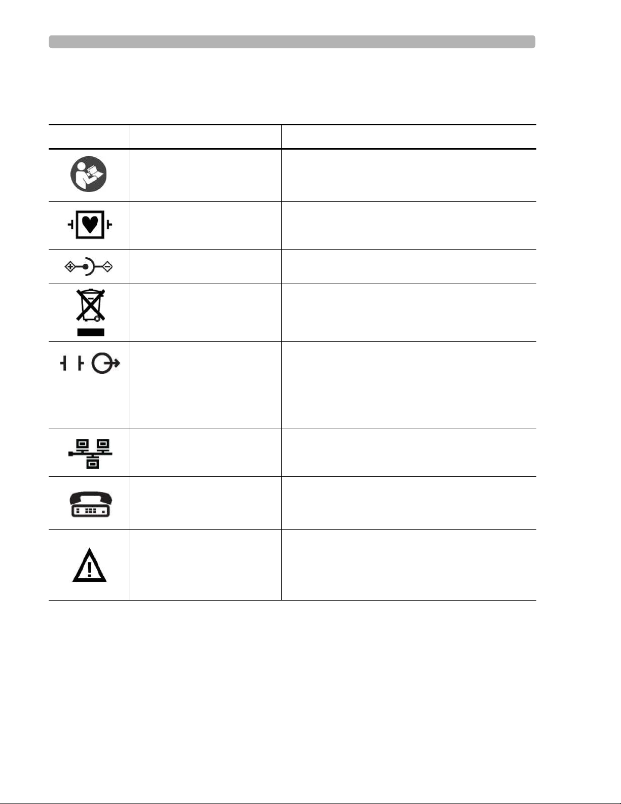
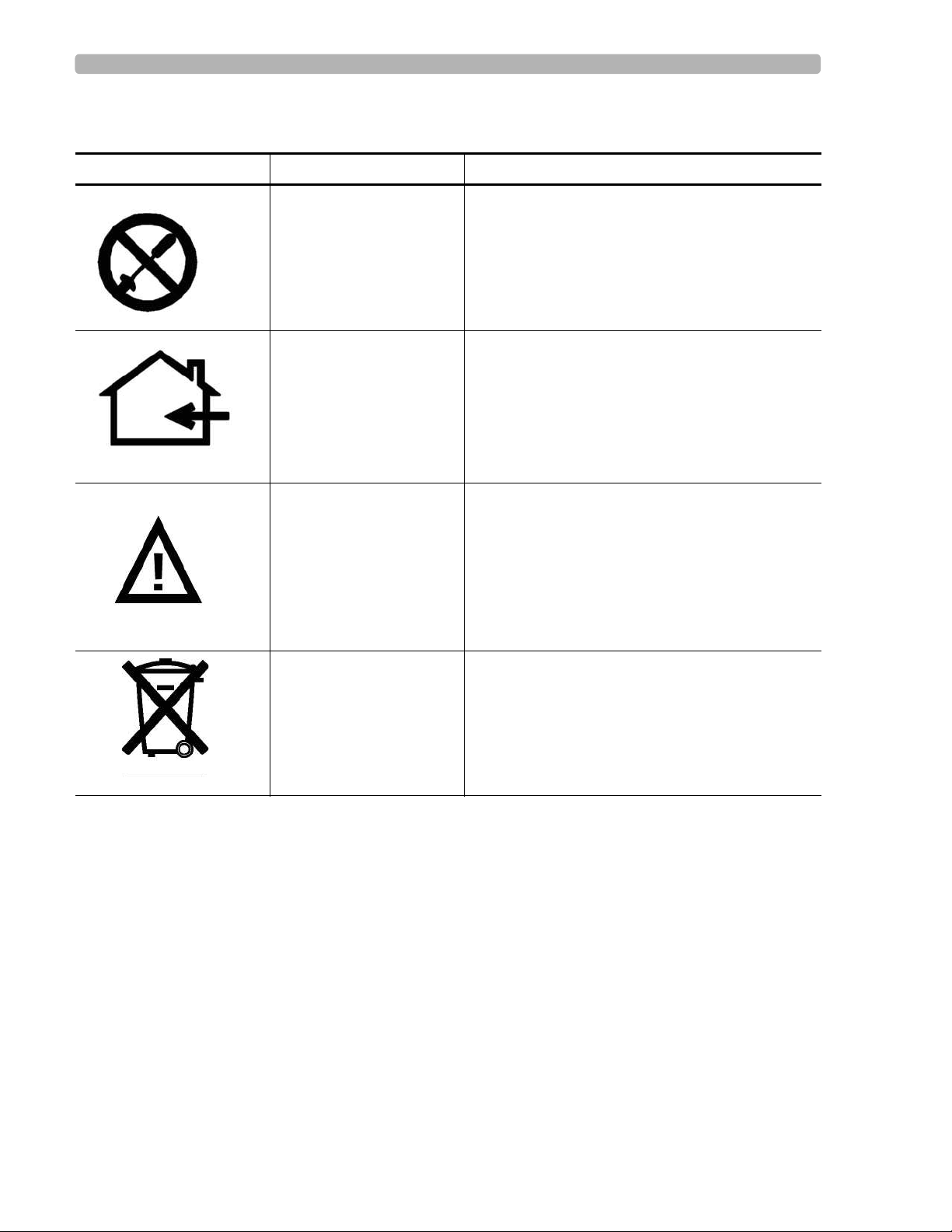
Symbols Marked on the Cardiograph
Symbol Name Description
Attention; read the Instructions
for Use
Type CF ECG physio isolation is type CF, defibrillator proof.
Direct current Indicates that the equipment is suitable for direct
Disposal Dispose of in accordance with the requirements of
ECG output signal The connector near this symbol provides access to an
Local Area Network (LAN)
Connector
See the PageWriter TC70 Cardiograph Instructions
for Use.
Suitable for all patient applications including direct
cardiac application. System is in continuous operation.
current only.
your country.
analog ECG signal that can be used as a
synchronization signal for external devices, such as an
imaging device. This analog ECG signal is not
diagnostic quality and should not be used for ECG
analysis purposes.
Connect the Ethernet RJ45 LAN cable to the connector
directly beneath this symbol to establish LAN
connectivity.
Modem Connector Connect an analog phone line to the connector directly
beneath this symbol.
Attention; read the Instructions
for Use
See the PageWriter TC70 Cardiograph Instructions
for Use.
PageWriter TC 70 Cardiograph Service Manual 1-5
Page 14
Introduction Safety Summary
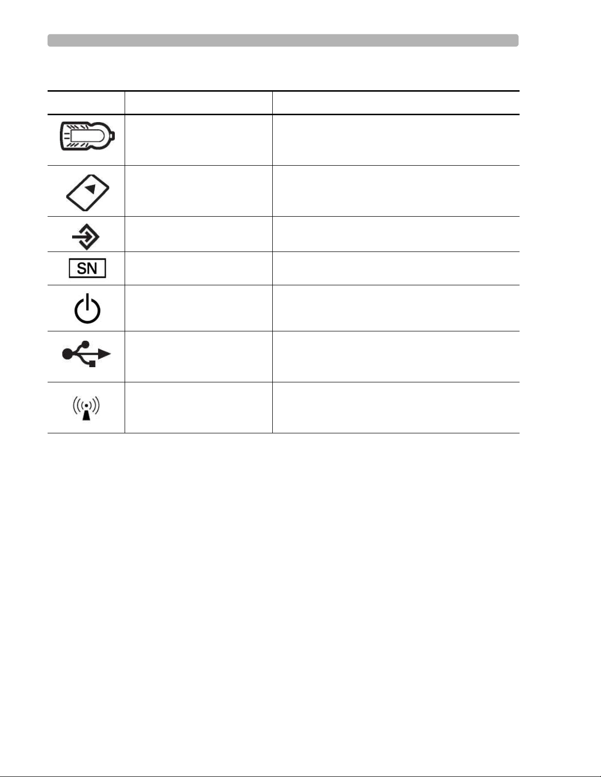
Symbols Marked on the Cardiograph
Symbol Name Description
Patient Interface Module (PIM)
Connector
Connect the PIM patient data cable to the connector
located directly beneath this symbol.
PCMCIA icon Insert the wireless LAN card into the slot located
directly beneath this symbol.
PS/2 Connector Connect the Magnetic Card Reader or Barcode Reader
to the connector located directly beneath this symbol.
Option Number The number next to this symbol is the serial number of
the cardiograph.
Standby Pressing the button with this symbol on it puts the
cardiograph into Standby (power saving mode).
USB Connector The connector near this symbol is used with a USB
device.
Non-ionizing electromagnetic
radiation
Interference may occur in the vicinity of equipment
marked with this symbol.
1-6 PageWriter TC 70 Cardiograph Service Manual
Page 15
Safety Summary Introduction
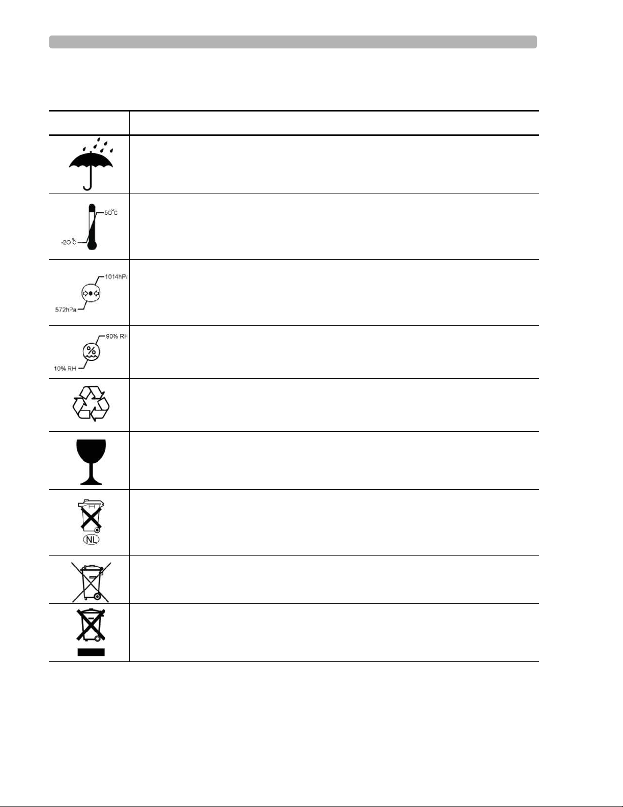
Safety Symbols Marked on the Cardiograph Packaging
Symbol Description
Keep dry.
o
Ambient temperature range of -20
transport and storage.
Atmospheric pressure range of 4572 meters (15,000 feet), 572 hPA above sea level for
transport and storage.
Relative humidity range of 10% to 90% (non-condensing) for transport and storage.
C (-4o F) to 50 oC (122o F) (non-condensing) for
Made from recycled materials.
Fragile.
Lithium ion battery. Do not dispose of in trash. Follow local regulations for disposing of
as small chemical waste.
This product consists of devices that may contain mercury, which must be recycled or
disposed of in accordance with local, state, or federal laws. (Within this system, the
backlight lamps in the monitor display contain mercury.)
Dispose of in accordance with the requirements of your country.
PageWriter TC 70 Cardiograph Service Manual 1-7
Page 16
Introduction Safety Summary
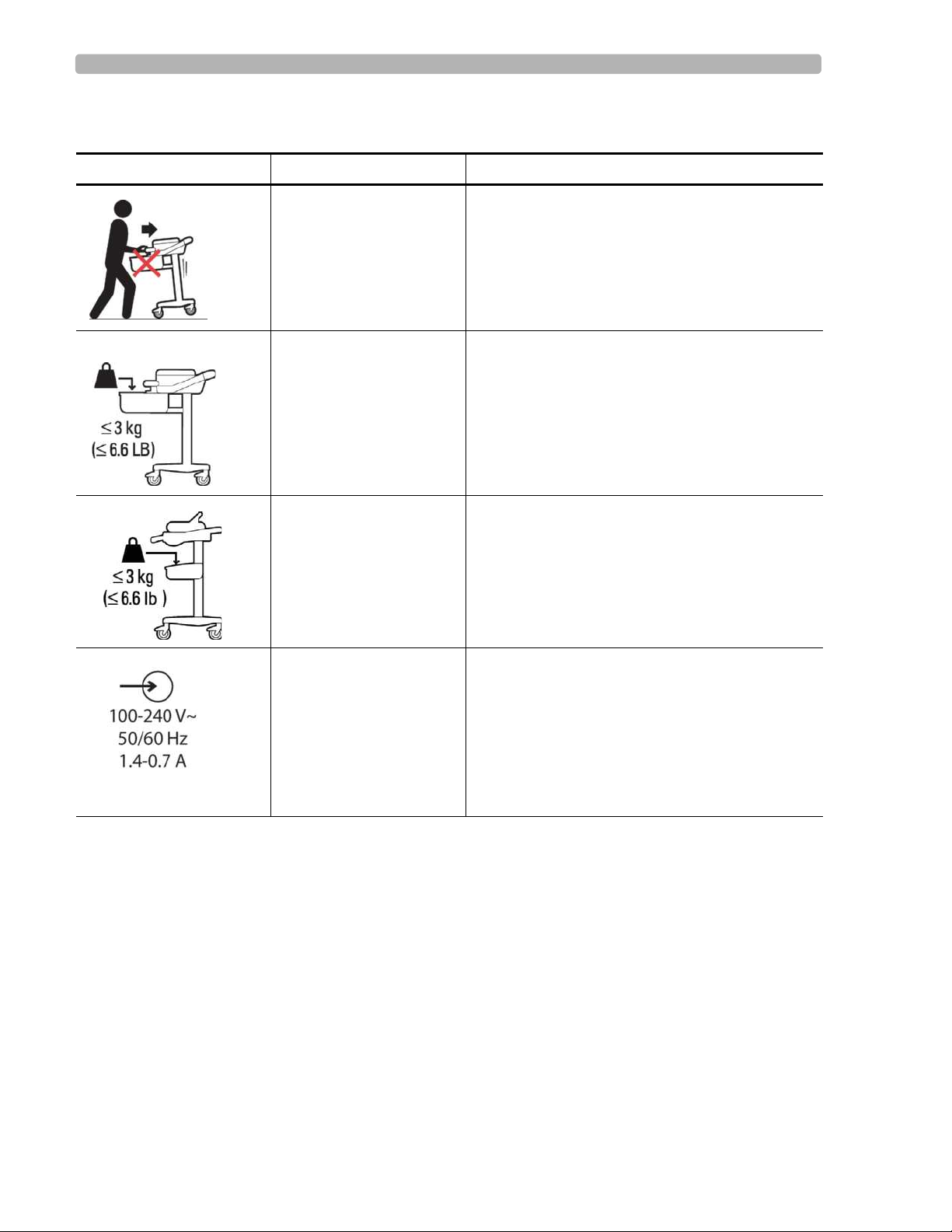
Safety and Regulatory Symbols Marked on the Cart
Symbol Name Description
Cart Transport Do not transport the cart with the drawer open.
Cart Drawer Weight
Limit
Cart Storage Bin Weight
Limit
AC power connector
input
Do not place more than 3 kilograms or 6.6
pounds of weight into the cart drawer.
Do not place more than 3 kilograms or 6.6
pounds of weight into the cart storage bin.
Indicates the location of the cardiograph AC
power connector.
1-8 PageWriter TC 70 Cardiograph Service Manual
Page 17
Safety Summary Introduction
Safety and Regulatory Symbols Marked on the AC Power Adapter
Symbol Name Description
No serviceable parts
inside
Indoor, dry location use
only
Attention; read the
Instructions for Use
There are no serviceable parts inside the AC
adapter. Do not open the AC adapter case.
The AC adapter is only intended for indoor use in
a dry location.
See the PageWriter TC70 Cardiograph
Instructions for Use for information on the AC
power adapter.
AC adapter disposal Dispose of in accordance with the requirements
of your country.
PageWriter TC 70 Cardiograph Service Manual 1-9
Page 18

Introduction Important Patient and Safety Information
Important Patient and Safety Information
The PageWriter TC70 cardiograph isolates all connections to the patient from electrical
ground and all other conductive circuits in the cardiograph. This reduces the possibility of
hazardous currents passing from the cardiograph through the patient’s heart to ground.
WARNING Failure to follow these warnings could affect both patient and operator safety.
Accessories and Supplies
WARNING Always clean and disinfect reusable electrodes before patient use. Failure to properly
clean and disinfect reusable electrodes before patient use may cause infectious materials
to be transferred between patients.
WARNING The Welsh bulb electrodes (available as an accessory for the cardiograph) do not meet
the requirements of IEC 60601-2-25 for defibrillation recovery time, and cannot be
reliably used for patient diagnosis immediately following defibrillation.
WARNING When using additional peripheral equipment powered from an electrical source other
than the cardiograph, the combination is considered to be a medical system. It is the
responsibility of the operator to comply with IEC 60601-1-1 and test the medical system
according to the requirements. For additional information contact Philips Medical
Systems.
WARNING Do not use non-medical peripherals within 6 feet of a patient unless the non-medical
peripherals receive power from the cardiograph or from an isolation transformer that
meets medical safety standards.
CAUTION The Welsh bulb electrodes contain natural rubber latex which may cause allergic reactions.
When using additional peripheral equipment powered by an electrical source other than the
cardiograph, the combination of
Using accessories, peripherals, or cables that are not supplied with the cardiograph or that
are not recommended by Philips Medical Systems can result in increased emissions or
decreased immunity of the cardiograph.
Only use Philips Medical Systems replacement parts and supplies with the cardiograph. The
use of non-approved replacement parts and supplies with the cardiograph is strictly
prohibited. Cardiograph safety and performance are not guaranteed when non-approved
replacement parts and supplies are used with the cardiograph.
1-10 PageWriter TC 70 Cardiograph Service Manual
Page 19

Important Patient and Safety Information Introduction
Connect other equipment in accordance with IEC 60601-1-1 Medical Electrical Systems
Standard or IEC 60601-1: 2005 (3rd Edition) Medical Electrical Equipment Standard
Clause 16 Medical Electrical Systems.
When connecting the cardiograph to other AC powered equipment, only connect equipment
approved to IEC 60601-1 Medical Electrical Equipment or IEC 60950-1 Information
Technology Equipment.
Only use patient electrodes that are approved by Philips Medical Systems. The use of non-
approved patient electrodes may degrade cardiograph performance.
To prevent burns to the patient, remove all ECG electrodes and lead wires prior to the use of
high frequency surgical equipment (including electrosurgical equipment and some
respiration transducers).
The use of equipment that applies high frequency voltages to the patient (including
electrosurgical equipment and some respiration transducers) is not supported and may
produce undesired results.
AC Power Adapter and AC Power Cord
CAUTION The power supply could feel warm to the touch.
The PageWriter TC70 cardiograph external power supply, part number 453564094411 is
designed with a three wire supply system. The ground only serves a functional purpose for
EMC and not protective earth for electrical safety. Use of an appropriate three-wire power
cord is necessary to provide proper EMC operation.
Only use the AC power adapter designed to be used with the PageWriter TC70 cardiograph,
part number 453564094411, in order to ensure continued compliance with the requirements
of IEC 60601-1.
Only use the external power supply with part number 453564094411 with the PageWriter
TC70 cardiograph to prevent electrical safety hazards. The use of any other power supply is
not approved by Philips Medical Systems.
To disconnect the cardiograph from AC power, unplug the cardiograph AC power cord
from the mains power supply.
This equipment complies with the earth leakage current limits as specified in UL 60601-
1:2003 Medical Electrical Equipment - General Requirements for Safety, only when
connected to a 120 Volt mains power supply.
Use only grounded power cords (three-wire power cords with grounded plugs) and
grounded electrical outlets. Never adapt a grounded plug to fit an ungrounded outlet by
removing the ground prong or ground clip.
Periodically inspect the patient data cable, lead wires, and AC power cord for any worn or
cracked insulation. Ensure that no exposed wires are visible on the AC power cord.
PageWriter TC 70 Cardiograph Service Manual 1-11
Page 20

Introduction Important Patient and Safety Information
Only use the Philips Medical Systems AC power supply (part number 453564094411)
supplied with the cardiograph. Use of any other power supply has not been verified and may
lead to operator or patient harm, including electrical shock. Periodically inspect the AC
power cord and AC power connector to ensure that both are in a safe and operable
condition. If the AC power cord or AC power connector is not in a safe or operable
condition, operate the cardiograph on battery power and contact Philips Medical Systems
for service.
Analog ECG Output Signal Port
Do not use the analog ECG output signal port (not supported on cardiograph) for diagnostic
purposes and do not use this signal for critical synchronization timing.
Do not connect any equipment to the cardiograph analog ECG output signal port that does
not meet medical safety requirements and that has not been evaluated by local safety
personnel.
Batteries
CAUTION When removing the batteries from the cardiograph, the batteries could feel warm to the touch.
The PageWriter TC70 cardiograph is designed to be operated with two batteries installed,
and the battery operational time listed in this Instructions for Use is based upon cardiograph
operation with both batteries installed. Operation with a single battery is not supported or
recommended as it will shorten operational time and decrease overall battery life.
Only use the batteries designed to be used with the PageWriter TC70 cardiograph, part
number 989803144631, in order to ensure continued compliance with the requirements of
IEC 60601-1.
Cart
Ensure that the cardiograph is securely attached to the cardiograph cart before use.
Defibrillation
Do not touch the patient, patient data cable, or cardiograph during defibrillation. Death or
injury may occur from the electrical shock delivered by the defibrillator.
Diagrams
Upon customer request, Philips Medical Systems will make available circuit diagrams,
component part lists, descriptions, calibration instructions and other technical information.
1-12 PageWriter TC 70 Cardiograph Service Manual
Page 21

Important Patient and Safety Information Introduction
Display Accuracy
The accuracy of the ECG signals are within +/- 5% (or +/- 40 uV whichever is greater), over
a range of 0 to 5 mV, in the presence of differential and common mode DC offset voltages
of +/- 300 mV. The cardiograph performance is tested to comply with the accuracy
requirements over the dynamic ranges and frequency ranges specified in the IEC 60601-251 and AAMI EC-11 standards.
For additional details regarding accuracy and precision, refer to the Physician's Guide and
the Manufacturer's Disclosure Statement.
ECG Interpretation
CAUTION Always enter accurate patient information (including age and gender) if using the Philips ECG
Algorithm for ECG interpretation.
Electrodes
Philips recommends the use of disposable electrodes at all times for all patient applications.
Choose either adult or pediatric disposable electrodes based on the age and size of the
patient. See “Disposable and Reusable Electrodes” on page 5-8 for information on ordering
disposable electrodes.
Faxed ECGs
CAUTION No guarentee is made as to the suitability of a faxed ECG for any particular purpose, due to the
variability inherent in fax technology.
General Cardiograph Use
Do not use this cardiograph near flammable anesthetics. It is not intended for use in
explosive environments or in operating rooms. The disconnection or connection of AC
power, or electrostatic discharge (ESD) may result in an electrical spark.
The cardiograph may generate electromagnetic interference (EMI) that may cause nearby
equipment to fail.
Connecting multiple cardiographs to the same patient may pose a safety hazard due to the
summation of leakage currents. Any combination of instruments should be evaluated by
local safety personnel before being put into service.
IEC 60601-2-51
For information on the standard IEC 60601-2-51, please go to the Philips InCenter web site
(
incenter.medical.philips.com).
PageWriter TC 70 Cardiograph Service Manual 1-13
Page 22

Introduction Important Patient and Safety Information
Lead Wires
WARNING Electrical shock hazard. Do not touch accessible connector pins and the patient
simultaneously.
Ensure that the electrodes or lead wires do not come in contact with any other conductive
materials (including earth-grounded materials) especially when connecting or disconnecting
electrodes to or from a patient.
Main Waveform Display Screen
Manual measurements of ECG intervals and magnitudes should be performed on printed
ECG reports only. Do not make manual measurements of ECG intervals and magnitudes on
the main waveform display screen since these ECG representations are scaled.
Modem Card and Fax Feature
WARNING Do not connect the modem card to a phone line when the cardiograph is connected to a
patient.
No guarantee is made as to the suitability of a faxed ECG report for any particular purpose,
due to the variability inherent in fax technology.
Pacemaker
Pace pulses may not be visible on a printed ECG report that uses simultaneous acquisition.
Patient Data Cable
Keep the patient data cable away from power cords and any other electrical equipment.
Failure to do so can result in AC power line frequency interference on the ECG trace.
The Philips Medical Systems patient data cable (supplied with cardiograph) is an integral
part of the cardiograph safety features. Use of any other patient data cable may compromise
defibrillation protection and degrade cardiograph performance.
Periodically inspect the patient data cable for any cracks or breaks in the cable insulation. If
the integrity of the patient data cable is not assured, replace the patient data cable. Contact
Philips Medical Systems for further assistance.
1-14 PageWriter TC 70 Cardiograph Service Manual
Page 23

Important Patient and Safety Information Introduction
Patient Interface Module (PIM)
Always put the cardiograph in Standby before replacing the Patient Interface Module
(PIM). Do not change the PIM while the cardiograph is in active use.
If using the optional, 16-lead PIM, always ensure that the leads connected to the Patient
Interface Module (PIM) are the same leads that are displayed on the cardiograph screen.
Printer
Do not pull on the paper while an ECG report is being printed. This can cause distortion of
the waveform and can lead to potential misdiagnosis.
Servicing the Cardiograph
Only qualified personnel may service the cardiograph or may open the cardiograph housing
to access internal cardiograph components. Do not open any covers on the cardiograph.
There are no internal cardiograph components that are serviced by the operator.
The Philips Medical Systems warranty is applicable only if you use Philips Medical
Systems approved accessories and replacement parts. See “Parts and Supplies” on page 5-1
for more information.
Software
Only install Philips Medical Systems software on the cardiograph. The installation or use of
software not approved by Philips Medical Systems is strictly prohibited and cardiograph
safety and performance are not guaranteed.
Touch Screen
Do not use sharp objects with the touch screen or apply excessive force to the touch screen.
Applying excessive force to the touch screen may result in breaking the touch screen
display and can cause sharp, jagged parts to expel to persons nearby.
Manual measurements of ECG intervals and magnitudes should be performed on printed
ECG reports only. Do not make manual measurements of ECG intervals and magnitudes on
the touchscreen display since these ECG representations are scaled.
PageWriter TC 70 Cardiograph Service Manual 1-15
Page 24
Introduction PageWriter TC70 Cardiograph Components
USB Memory Stick
CAUTION Only use the USB memory stick that is available for purchase as an optional accessory from Philips
Medical Systems with the PageWriter TC cardiograph.
Do not insert a USB memory stick into the cardiograph, or remove a USB memory stick from the
cardiograph when the cardiograph is acquiring ECG data from the patient.
Only use the USB memory stick to transfer data between the cardiograph and a computer. Do not use
the USB memory stick with other devices.
Do not import ECGs into the cardiograph from another cardiograph, or from other devices
to the cardiograph using a USB memory stick.
PageWriter TC70 Cardiograph Components
The following sections include a description of all of the components of the cardiograph,
including the connection ports on the cardiograph, the Patient Interface Module (PIM), and
optional accessories available with the cardiograph.
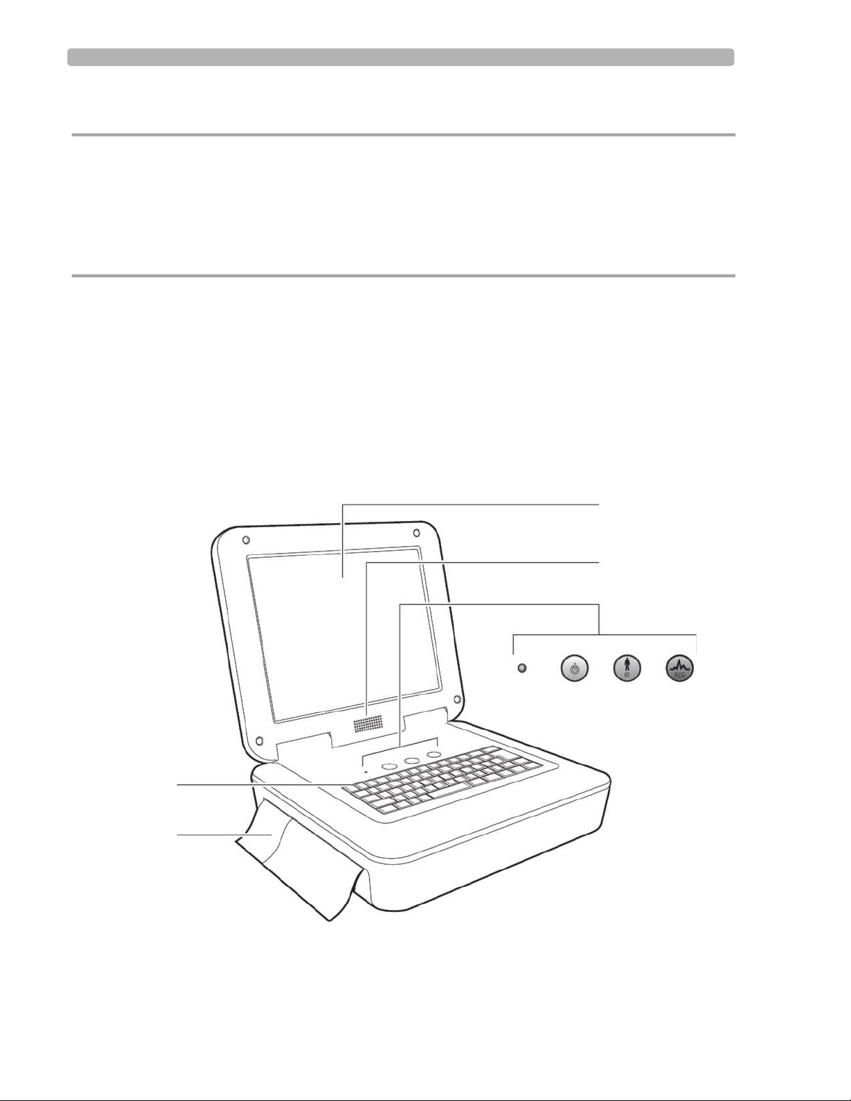
Figure 1-1 Cardiograph (left front view)
H
G
A
B
DEC
F
A Touch screen F ECG button
B Audio speaker G Paper tray
C AC power on indicator light H Keyboard
1-16 PageWriter TC 70 Cardiograph Service Manual
Page 25
PageWriter TC70 Cardiograph Components Introduction
D On/Off button
E ID button
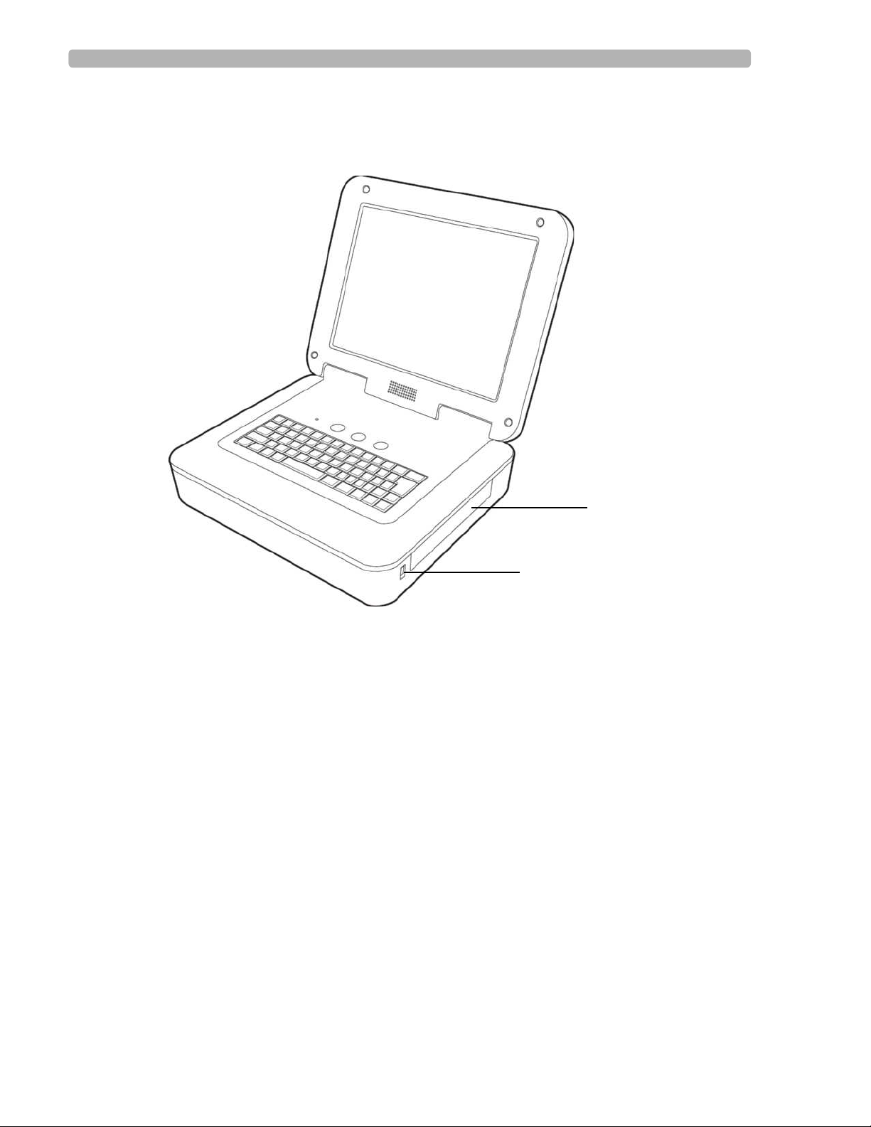
Figure 1-2 Cardiograph (right front view)
I Battery compartment
J USB memory stick connector
F
G
PageWriter TC 70 Cardiograph Service Manual 1-17
Page 26
Introduction PageWriter TC70 Cardiograph Components
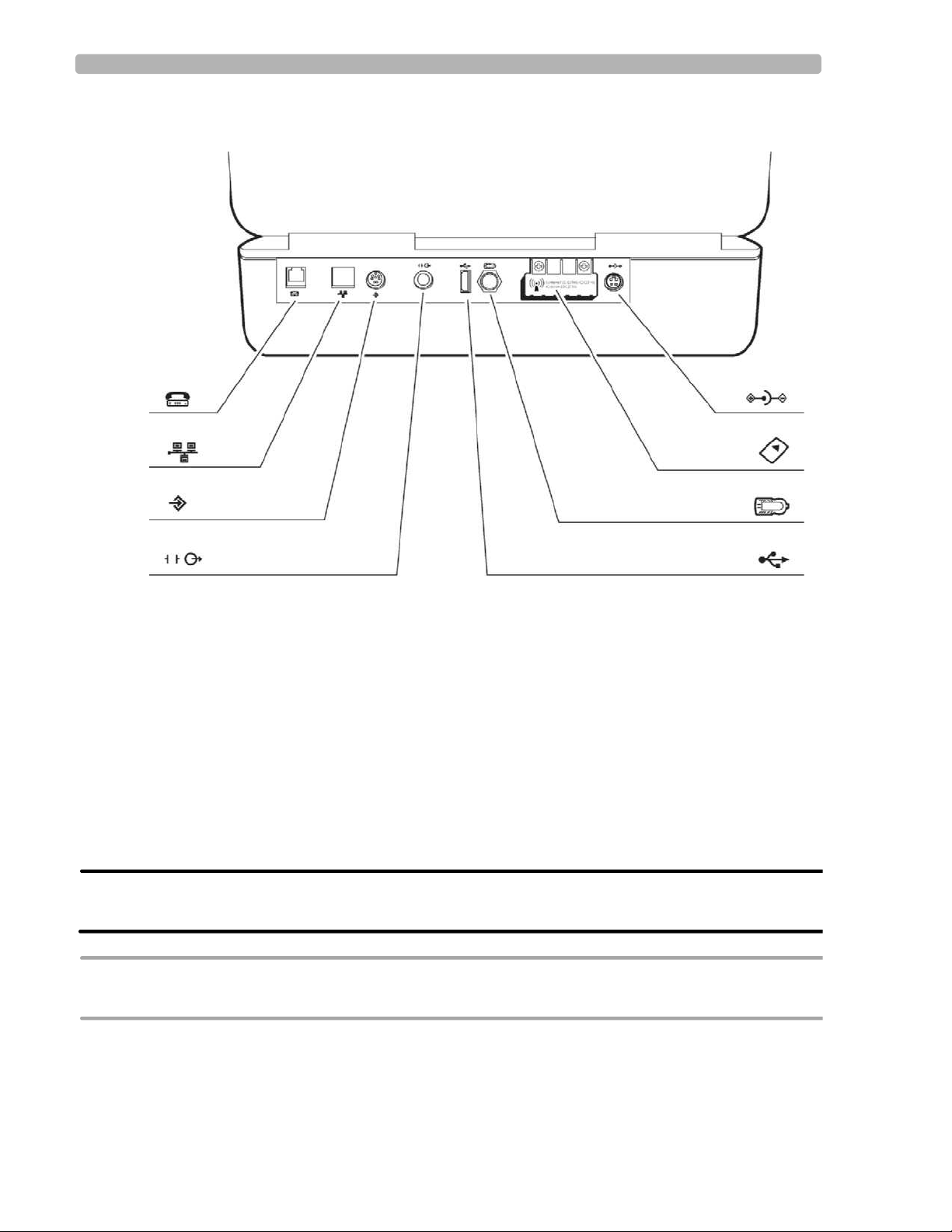
Figure 1-3 Cardiograph (rear view)
A
B
C
D
A Modem connector G Wireless LAN card slot (with protective
cover installed)
B LAN connector H AC power connector
C Barcode reader or magnetic card reader
connector
D Analog ECG output signal connector (not
supported)
E USB connector
F PIM connector
H
G
F
E
WARNING Do not connect the modem card to a phone line when the cardiograph is connected to a
patient.
CAUTION Do not insert a USB memory stick into the cardiograph, or remove a USB memory from the
cardiograph when the cardiograph is acquiring ECG data from a patient.
1-18 PageWriter TC 70 Cardiograph Service Manual
Page 27
Patient Interface Module (PIM) Introduction
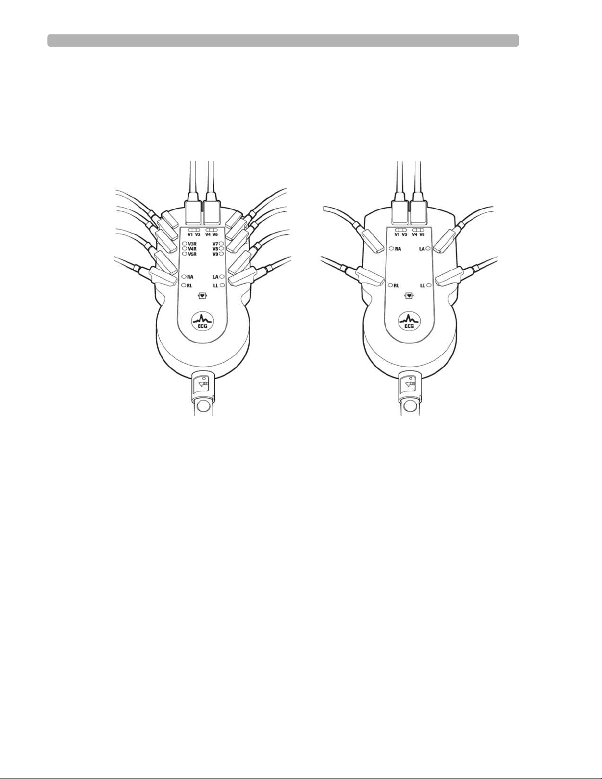
Patient Interface Module (PIM)
The Patient Interface Module (PIM) is a hand-held device that connects to the patient data
cable. The PIM is available in a standard 12-lead, or an optional 16-lead model. The PIM is
shipped with the patient data cable fully connected to the PIM.
Figure 1-4 16-lead (left) and 12-lead (right) Patient Interface Module (PIM)
PageWriter TC 70 Cardiograph Service Manual 1-19
Page 28
Introduction Installing the Batteries
Installing the Batteries
The cardiograph is shipped with two batteries that are used to power the cardiograph when AC
power is not available.
CAUTION Insert the batteries into the cardiograph before plugging the cardiograph into AC power.
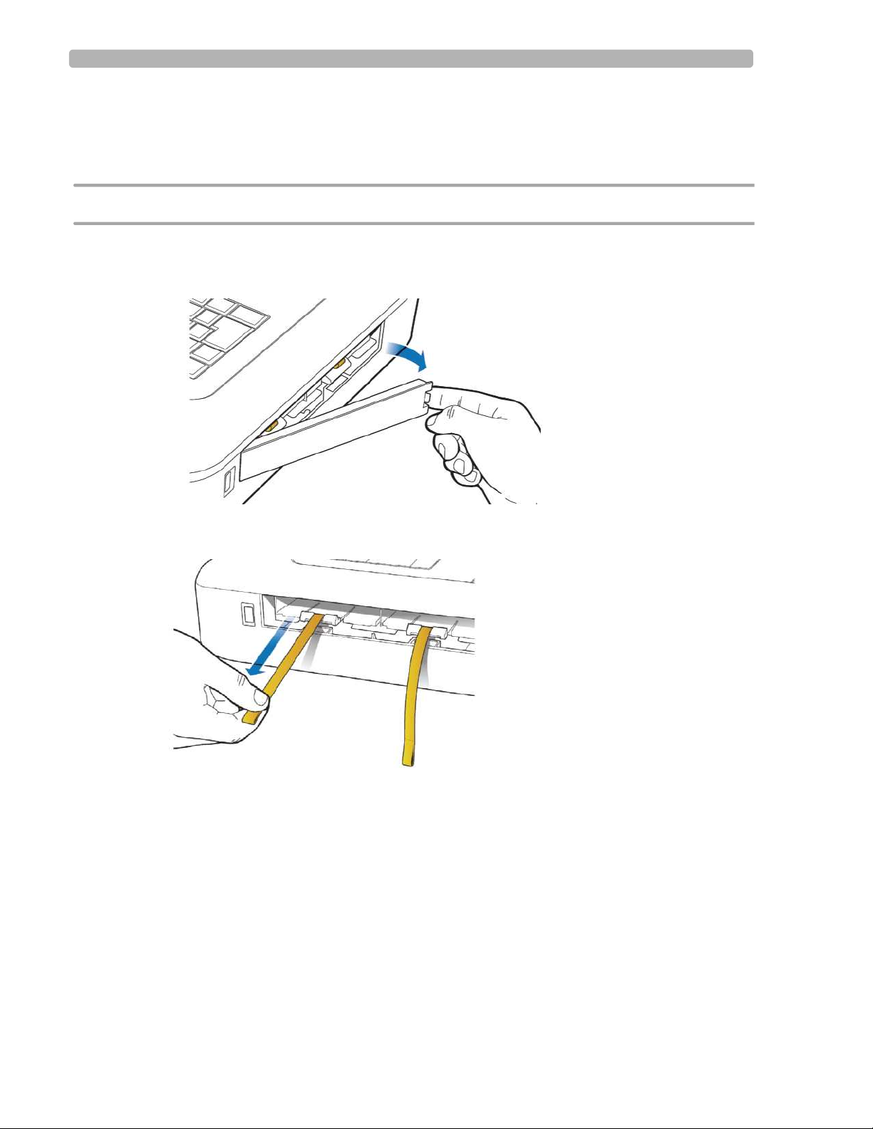
To install the batteries:
1
Open the battery door.
2 Locate the two gold pull tabs inside of the battery compartment. Pull the tabs straight out
of the battery compartment and ensure that both are pulled taut.
1-20 PageWriter TC 70 Cardiograph Service Manual
Page 29
Installing the Batteries Introduction
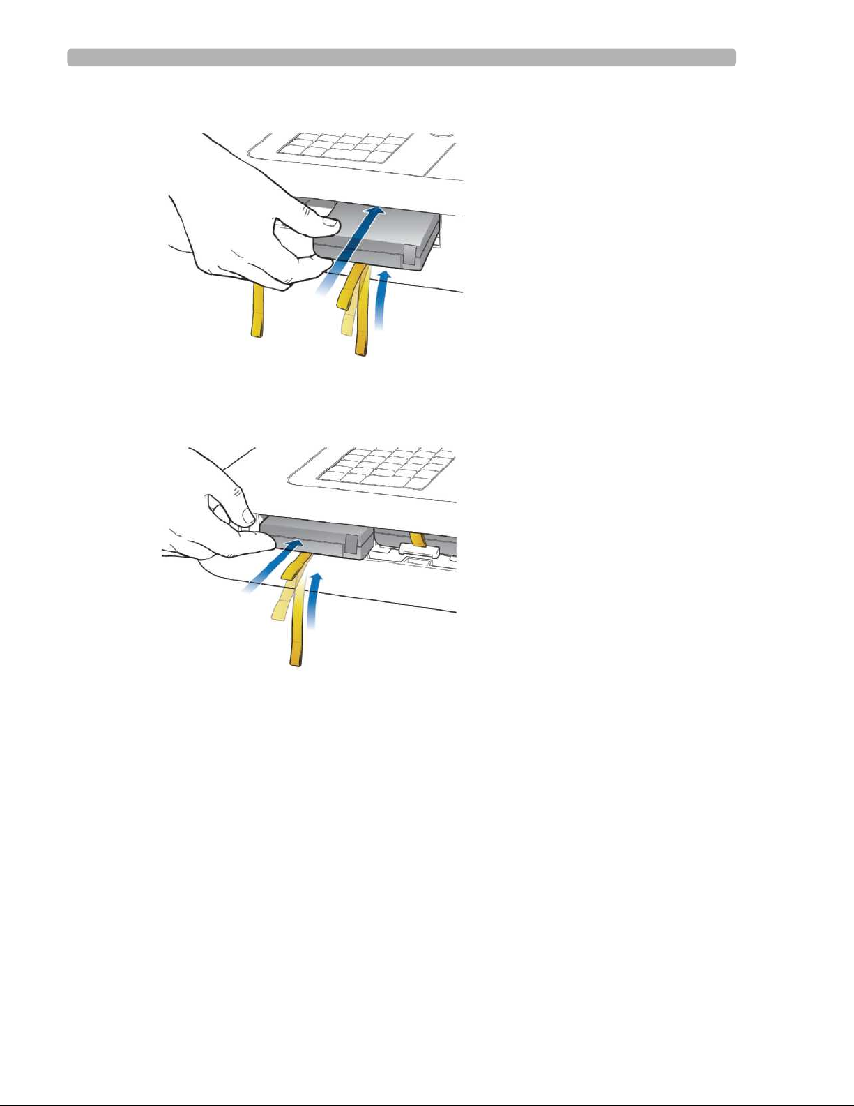
3 Insert the battery with the external connector facing the bottom rear of the compartment.
4 Ensure that the battery is fully inserted into the slot. The pull tab will insert along with the
battery. Insert the second battery following the same procedure.
PageWriter TC 70 Cardiograph Service Manual 1-21
Page 30
Introduction Installing the Batteries
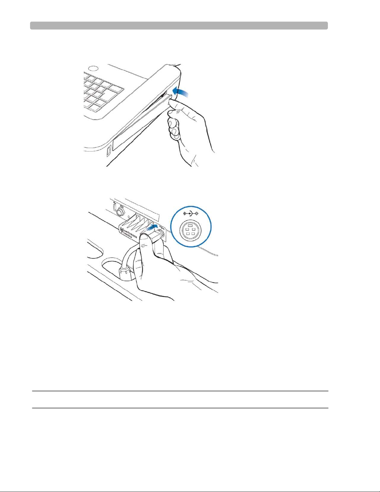
5 Reinstall the battery door.
6 Connect the AC power cord to the cardiograph. Charge the batteries for five hours before
operating the cardiograph on battery power only.
Charging the Batteries
Charge the batteries for five hours prior to initial use. Plug the cardiograph into AC power
whenever possible, and fully charge the batteries. Proper battery maintenance and care,
including frequent and full charging of the batteries, will help to prolong battery life.
There are configurable power saving features available on the cardiograph. These features are
used to help prolong overall battery life, and to optimize battery power use between battery
charges.
CAUTION When removing the batteries from the cardiograph, the batteries could feel warm to the touch.
1-22 PageWriter TC 70 Cardiograph Service Manual
Page 31

Installing the Batteries Introduction
Calibrating the Batteries
The batteries may require periodic calibration to ensure the continued accuracy of the battery
power and overall battery status information displayed on the cardiograph. For more
information on battery calibration, see “Battery Calibration” on page 2-14.
Battery Power Indicator
The battery power indicator appears on the Status Bar and is always visible. The indicator
displays the current battery power level. The cardiograph can operate on AC power while the
batteries are charging, but the batteries will charge at a slower rate.
Figure 1-5 Battery Power Indicator on the Status Bar
A Battery level indicator
Double-tap the Battery Power Indicator on the Status Bar to ensure that the batteries are fully
charged.
A
To check the battery power level:
Double-tap on the battery icon on the Status Bar. The Battery Status Information window
1
appears. This window provides detailed information on the status of the cardiograph
batteries.
NOTE If the Plug in the Cardiograph message appears, the cardiograph needs to be plugged into AC
power immediately.
Figure 1-6 Battery Status Information
PageWriter TC 70 Cardiograph Service Manual 1-23
Page 32

Introduction Using the Wireless LAN Card
2 Touch the Close button to close the window.
Table 1-1 Battery Level Indicator Information (icon on Status Bar)
Battery Level Icon on Status Indicator
Fully Charged Battery
75% power capacity
50% power capacity
Low Battery Power:
red battery icon appears when power level is between
20-30%
cardiograph beeps and an error message appears until
the unit is plugged into AC power (audio feature may
be disabled)
double-tap the icon to see how many minutes are left of
operating battery power
No or Dead Battery
Using the Wireless LAN Card
The PageWriter TC70 cardiograph supports the Summit Wireless LAN card. The wireless
LAN card is used to transfer ECG and order data between the cardiograph and a TraceMaster
ECG Management System.
CAUTION Only use wireless LAN cards with the PageWriter TC70 cardiograph that have been purchased from
Philips Medical Systems. The use of non-approved wireless LAN cards with the PageWriter TC70
cardiograph is not tested or supported, and Philips Medical Systems does not guarantee cardiograph
operation or wireless LAN connectivity.
For information on installing the card and configuring the cardiograph for wireless
transmission, see the PageWriter TC70 Cardiograph Wireless LAN Installation Instructions.
The file is available for download from the Philips InCenter site.
1-24 PageWriter TC 70 Cardiograph Service Manual
Page 33

Using the Modem Module Introduction
Using the Modem Module
The modem module is an optional accessory that is used to fax ECGs to a configured receiving
fax machine, or is used to transfer ECGs or orders by modem to a TraceMaster ECG
Management System. The modem module used either as a fax or as a modem must be
configured before initial use with the cardiograph. For information on configuring the modem
module to transmit data to a TraceMaster ECG Management System, see the PageWriter
TC70 Cardiograph Network Configuration Guide available on the User Documentation CD,
or the file can be downloaded from the Philips InCenter site.
WARNING Do not connect the modem module to a phone line when the cardiograph is connected
to a patient.
Using the USB Memory Stick
The USB memory stick is an optional accessory that is used to transfer orders to the
cardiograph from a computer that has the WebSelect Utility installed, and can also be used to
transfer completed ECGs from the cardiograph to a TraceMaster ECG Management System
for reconciliation and processing. The USB memory stick can also be used to save custom
settings specified on the Setup screens as a Custom Settings file. This Custom Settings file can
then be transferred to additional cardiographs to help speed up the configuration process.
For information on using the WebSelect Utility, see the Using OrderVue with PageWriter
Cardiographs guide on the User Documentation CD, or download the file from the Philips
InCenter site.
CAUTION The PageWriter TC70 cardiograph only supports the USB memory stick that is available for purchase
as an optional accessory from Philips Medical Systems. Philips does not guarantee that other USB
memory sticks are compatible with the PageWriter TC70 cardiograph.
PageWriter TC 70 Cardiograph Service Manual 1-25
Page 34

Introduction Using the USB Memory Stick
Figure 1-7 USB memory stick inserted into USB connector
A
A USB memory stick inserted into USB connector (tip illuminates when properly inserted)
The USB memory stick can store a combined total of up to 200 ECGs or orders. Ensure that
the USB memory stick is firmly inserted into the USB connector located on the front right side
of the cardiograph (next to the battery door). The tip of the USB memory stick illuminates
when it is properly inserted into the USB connector.
CAUTION Do not insert a USB memory stick into the cardiograph, or remove a USB memory from the
cardiograph when the cardiograph is acquiring ECG data from a patient.
CAUTION Only use the USB memory stick to transfer data between a PageWriter TC70 cardiograph and a
computer. Do not use the memory stick with other devices.
1-26 PageWriter TC 70 Cardiograph Service Manual
Page 35

Using the Barcode Reader Introduction
Using the Barcode Reader
The barcode reader is an optional accessory that is used to quickly enter ID information by
scanning a barcode.
The barcode reader attaches to the barcode reader connector ( ) on the rear panel of the
cardiograph. Attach the barcode reader to the cardiograph before turning on AC power.
Figure 1-8 The Barcode Reader
Using the Keyboard Shortcuts
The following key stroke combinations can be used from any cardiograph screen.
Table 1-2 Keyboard Shortcuts
Keyboard Shortcut Action
Ctrl
+ Alt + C Runs the Touch Screen Calibration test. See “Touch Screen
Calibration and Test” on page 3-41 for more information.
Ctrl + Alt + P Saves the current cardiograph screen to a USB memory stick.
PageWriter TC 70 Cardiograph Service Manual 1-27
Page 36

Page 37

2
1Cardiograph Care and Maintenance
The following chapter contains information about basic cardiograph care, and periodic
cardiograph maintenance that may be required.
This chapter provides the following information:
Cardiograph and PIM Cleaning . . . . . . . . . . . . . . . . . . . . . . . . . . . .2-3
Approved Cleaning Solutions . . . . . . . . . . . . . . . . . . . . . . . . . .2-3
Patient Data Cable and Lead Wire Cleaning . . . . . . . . . . . . . . . . . .2-4
Approved Cleaning Solutions . . . . . . . . . . . . . . . . . . . . . . . . . .2-4
Reusable Electrode Cleaning . . . . . . . . . . . . . . . . . . . . . . . . . . . . . .2-5
Cleaning the Print Head . . . . . . . . . . . . . . . . . . . . . . . . . . . . . . . . .2-6
Printer Paper. . . . . . . . . . . . . . . . . . . . . . . . . . . . . . . . . . . . . . . . . . .2-7
Tearing Paper. . . . . . . . . . . . . . . . . . . . . . . . . . . . . . . . . . . . . .2-10
Battery Maintenance and Care. . . . . . . . . . . . . . . . . . . . . . . . . . . .2-10
Replacing the Batteries . . . . . . . . . . . . . . . . . . . . . . . . . . . . . .2-11
Battery Calibration. . . . . . . . . . . . . . . . . . . . . . . . . . . . . . . . . . . . .2-14
Maintaining the Touch Screen . . . . . . . . . . . . . . . . . . . . . . . . . . . .2-16
Touch Screen Calibration . . . . . . . . . . . . . . . . . . . . . . . . . . . .2-16
Touch Screen Cleaning . . . . . . . . . . . . . . . . . . . . . . . . . . . . . .2-16
Changing the Date and Time . . . . . . . . . . . . . . . . . . . . . . . . . . . . .2-17
Cardiograph Overall Sensitivity Test . . . . . . . . . . . . . . . . . . . . . . .2-18
Before You Begin . . . . . . . . . . . . . . . . . . . . . . . . . . . . . . . . . .2-18
Performing the Sensitivity Test . . . . . . . . . . . . . . . . . . . . . . . .2-18
Cardiograph and Accessory Disposal . . . . . . . . . . . . . . . . . . . . . .2-19
2-1
Page 38

Cardiograph Care and Maintenance
Table 2-1 Recommended Frequency of Maintenance Tasks
Component Recommended
Frequency
Cardiograph and
Weekly “Cardiograph and PIM Cleaning” on page 2-3
Patient Interface
Module (PIM)
Cleaning
Patient Data Cable
Weekly “Patient Data Cable and Lead Wire Cleaning” on
and Lead Wire
Cleaning
Reusable
Electrode
After each
patient use
Cleaning
Print Head
Cleaning
When necessary
due to uneven
print quality
Battery
Calibration
When necessary,
due to inaccurate
battery status
information
displayed on
cardiograph
Maintenance Task and page number
page 2-4
“Reusable Electrode Cleaning” on page 2-5
“Cleaning the Print Head” on page 2-6
“Battery Calibration” on page 2-14
Touch screen
calibration
Touch screen
cleaning
Cardiograph
Overall Sensitivity
Test
When necessary,
“Touch Screen Calibration” on page 2-16
due to decreased
touch screen
performance
Weekly “Touch Screen Cleaning” on page 2-16
Yearly “Cardiograph Overall Sensitivity Test” on
page 2-18
2-2 PageWriter TC 70 Cardiograph Service Manual
Page 39

Cardiograph and PIM Cleaning Cardiograph Care and Maintenance
Cardiograph and PIM Cleaning
To clean the cardiograph and PIM:
Unplug the AC power cord.
1
2 Ensure that the AC power indicator light (next to power button) is not lit.
3 Wipe the external surfaces of the cardiograph and the PIM with a soft cloth dampened in
any of the approved cleaning solutions listed below.
CAUTION When cleaning, avoid the lead wire connectors and patient data cable connectors.
Approved Cleaning Solutions
Mild soap and water
Isopropyl alcohol (consisting of 70% solution in water)
Chlorine bleach (6% sodium hypo chlorite content), 3% solution in water
Quaternary ammonium compounds (21% quaternary ammonium content), for example,
Steris Coverage Plus NPD at a consistency of one half ounce per gallon of water (one part
Coverage Plus NPD to 255 parts water)
CAUTION Do not use strong solvents or abrasive cleaning materials.
Do not spill liquids on the surface of the cardiograph.
Do not use any of the following to clean the cardiograph:
Acetone
Iodine-based cleaners
Phenol-based cleaners
Ethylene oxide sterilization
The cardiograph or PIM should not be autoclaved, ultrasonically cleaned, or immersed.
PageWriter TC 70 Cardiograph Service Manual 2-3
Page 40

Cardiograph Care and Maintenance Patient Data Cable and Lead Wire Cleaning
Patient Data Cable and Lead Wire Cleaning
Approved Cleaning Solutions
Mild soap and water
Isopropyl alcohol (consisting of 70% solution in water)
Chlorine bleach (6% sodium hypo chlorite content), 3% solution in water
Quaternary ammonium compounds (21% quaternary ammonium content), for example,
Steris Coverage Plus NPD at a consistency of one half ounce per gallon of water (one part
Coverage Plus NPD to 255 parts water)
To clean the patient data cable and lead wires:
Dampen a soft cloth with soapy water or with one of the disinfectants or cleaning agents
1
listed in “Approved Cleaning Solutions” (above).
2 Wring excess moisture from the cloth before cleaning.
CAUTION Do not:
Autoclave the patient data cable or lead wires or use ultrasonic cleaners
Immerse
Use abrasive materials
Wet the connectors
2-4 PageWriter TC 70 Cardiograph Service Manual
Page 41

Reusable Electrode Cleaning Cardiograph Care and Maintenance
Reusable Electrode Cleaning
Reusable limb clamp and Welsh Bulb electrodes must be cleaned after each use.
WARNING Always clean and disinfect reusable electrodes before patient use. Failure to properly
clean and disinfect reusable electrodes before patient use may cause infectious materials
to be transferred between patients.
Figure 2-1 Welsh Bulb and Limb Clamp Electrode
To clean reusable electrodes:
1
For Welsh Bulb electrodes only: detach the rubber bulb from the metal cup by pulling.
Wash the rubber bulb in warm water. Remove all electrolyte gel residue, check inside the
rubber bulb to ensure that all residue is removed.
2 For all reusable electrodes: dampen a soft cloth with one of the disinfectants or cleaning
agents listed below.
Cidex Ortho Phthaladehyde
Cetylcide
Vesphene 2 Aqueous Phenolic Germicidal Agent
CAUTION Do not:
Use isopropyl alcohol
Autoclave the reusable electrodes or use ultrasonic cleaners
Use abrasive materials
3 Wring excess moisture from the cloth before cleaning.
4 Dry the bulb and cup of the Welsh Bulb electrode thoroughly before use.
PageWriter TC 70 Cardiograph Service Manual 2-5
Page 42

Cardiograph Care and Maintenance Cleaning the Print Head
5 Store the reusable electrodes away from direct sunlight and excessive heat when not in
use.
Cleaning the Print Head
Clean the print head periodically, as a dirty print head may cause poor or uneven print quality.
Clean the print more frequently when printing large volumes of ECGs.
Figure 2-2 Cleaning the Print Head
A
A Print head
To clean the print head:
Open the paper drawer (left side of cardiograph).
1
2 Wipe the print head lightly with a foam swab dipped in 90% alcohol.
3 Allow the print head to dry.
2-6 PageWriter TC 70 Cardiograph Service Manual
Page 43

Printer Paper Cardiograph Care and Maintenance
Printer Paper
Replace the printer paper when a red stripe appears on the printed ECG report. Only use
Philips Medical Systems replacement printer paper. For part ordering information, see
“Supplies and Ordering Information” on page 1-33.
To change the printer paper:
1
Open the paper drawer (left side of cardiograph) and remove any remaining sheets. Lift up
the paper hold down bar.
A
A Paper hold down bar
2 Insert a new pack of printer paper with the printed side facing up. Make sure that the hole
for the paper sensor is positioned as shown below.
PageWriter TC 70 Cardiograph Service Manual 2-7
Page 44

Cardiograph Care and Maintenance Printer Paper
A
A Paper sensor hole
2-8 PageWriter TC 70 Cardiograph Service Manual
Page 45

Printer Paper Cardiograph Care and Maintenance
3 Drape the first sheet over the roller and place the paper hold down bar on top of the paper.
A
A Paper hold down bar
4 Close the paper drawer.
PageWriter TC 70 Cardiograph Service Manual 2-9
Page 46

Cardiograph Care and Maintenance Battery Maintenance and Care
Tearing Paper
Tear off the printer paper as shown.
Figure 2-3 Tearing Off Printer Paper
Battery Maintenance and Care
The cardiograph has two removable lithium ion batteries that supply power to the cardiograph
during mobile use, and power the cardiograph printer while it is plugged into AC power.
For optimal battery performance:
Only use Philips Medical Systems lithium ion batteries (Philips part number
989803160981) with the cardiograph.
Before initial use, fully charge the batteries for five hours before operating the cardiograph
without AC power. Regularly and consistently charging the batteries will prolong battery
life.
Charging, storing, or using the batteries at temperatures above 50
the batteries and reduce overall battery life.
Check the battery power indicator on the Status Bar. Tap the battery icon on the Status Bar
for information on remaining battery power, see “Battery Power Indicator” on page 1-23.
Always charge the batteries when the cardiograph is not in use. Plug the cardiograph into
AC power. Ensure that the green AC power indicator light on the front of the cardiograph
is lit. The batteries will charge while the cardiograph is in use, but will charge at a slower
rate.
Operate the cardiograph, charge the batteries, and store the batteries at a room temperature
o
of 25
damage the batteries, and degrade overall cardiograph performance.
C (77o F) or lower. Exposure to higher temperatures may reduce battery life,
o
C (122o F) can damage
2-10 PageWriter TC 70 Cardiograph Service Manual
Page 47

Battery Maintenance and Care Cardiograph Care and Maintenance
If the cardiograph will be stored for more than sixty days without use, fully charge the
batteries, and then remove AC power from the cardiograph, and remove the batteries from
the cardiograph. Store the batteries in a cool, dry location. A set of fully charged batteries
stored outside the cardiograph will need to be recharged every sixty days.
Replacing the Batteries
WARNING Properly dispose of or recycle depleted batteries according to local regulations. Do not
disassemble, puncture, or incinerate the disposed batteries.
WARNING Carefully follow the instructions for replacing the batteries. Only use batteries with
Philips part number 989803160981.
CAUTION When removing the batteries from the cardiograph, the batteries could feel warm to the touch.
How often batteries need to be replaced depends on how well the battery is maintained and
how much it is used. If the batteries are fully charged but lose significant power after only a
few ECGs, consider replacement. For information on ordering replacement batteries, see
“Ordering Options and Upgrades” on page 1-37.
To install the batteries:
Unplug the cardiograph from AC power.
1
2 Open the battery door.
PageWriter TC 70 Cardiograph Service Manual 2-11
Page 48

Cardiograph Care and Maintenance Battery Maintenance and Care
3 Remove both batteries from the battery compartment by pulling on the gold straps.
4 Insert the battery with the external connector facing the bottom rear of the compartment.
2-12 PageWriter TC 70 Cardiograph Service Manual
Page 49

Battery Maintenance and Care Cardiograph Care and Maintenance
5 Ensure that the battery is fully inserted into the slot. The pull tab will insert along with the
battery. Insert the second battery following the same procedure.
6 Reinstall the battery door.
PageWriter TC 70 Cardiograph Service Manual 2-13
Page 50

Cardiograph Care and Maintenance Battery Calibration
7 Connect the AC power cord to the cardiograph. Charge the batteries for five hours before
operating the cardiograph on battery power only.
Battery Calibration
Battery calibration may be necessary in order to enhance the accuracy of the battery level
indicator that displays on the Status Bar. If the accuracy of this indicator is affected, the other
battery indicators included on the Battery Status window that is opened by tapping the battery
icon on the Status Bar may also be less accurate.
Figure 2-4 Battery Level Indicator on Status Bar
Battery Level
Indicator
The Estimated Remaining Runtime and Power (bar indicators) may not be accurate. The
recommended intervals for battery calibration are dependent upon factors in your clinical use
model. When the battery power indicators are not functioning so that they are useful in your
daily work environment, Philips recommends calibrating the batteries following the procedure
described in this section.
The battery calibration procedure requires that the cardiograph be taken out of active use for
up to 8 hours. If this is not practical for your specific clinical environment, an optional battery
charger/calibrator s available for purchase from Philips Medical Systems, using part number
989803162021. For more information on ordering the optional battery charger and calibrator,
see “Supplies and Ordering Information” on page 1-33.
2-14 PageWriter TC 70 Cardiograph Service Manual
Page 51

Battery Calibration Cardiograph Care and Maintenance
To calibrate the batteries on the cardiograph:
1
Attach the AC power cord to the cardiograph. Ensure that the AC power supply is
connected to a grounded electrical outlet and that the cardiograph is receiving AC power.
Check that the AC power indicator light (located next to the power button) is lit.
2 Fully charge the batteries.
3 To ensure that the batteries are fully charged, view the Charge Current field in the
Service Utility. Touch the
Setup button on the toolbar. Select the Service Utility from the
Setup main menu.
NOTE Accessing the Service Utility may require entering a password. If a password is lost and cannot be
retrieved, contact the Philips Response Center for assistance.
4
From the Service Utility screen, ensure that the About the Cardiograph button is selected
(top of screen). A selected button is highlighted in blue.
5 Underneath the Battery Status column (middle of screen), check that the Charge
Current
field for both batteries display 0 mA, ensuring that both batteries are fully
charged.
6 Touch the Print button (top of screen) to print out a report of the cardiograph settings
displayed on this screen.
7 Touch the Exit button (lower right hand corner of screen). Touch the Exit button again on
the Setup main menu.
8 Once the Main screen appears, touch the ID button to open the ID entry screen. Ensure
that the ID screen remains open.
9 Unplug the cardiograph from AC power. Ensure that the AC power indicator light (located
next to the power button) is not lit.
10 Keep the ID screen displayed and allow the batteries to deplete of all battery power. This
process will take approximately 8 hours to complete. When the batteries are depleted of all
power, the screen is black and the cardiograph cannot be returned to active use by
touching the power button.
11 Once the batteries are fully depleted, reconnect the cardiograph to AC power. Press the
power on the cardiograph to return it to active use.
12 On the Main screen, touch the Setup button.
13 Select the Service Utility from the Setup main menu.
14 From the Service Utility screen, ensure that the About the Cardiograph button is selected
(top of screen). A selected button is highlighted in blue.
15 Underneath the Battery Status column, check the Expected Max Error (%) and Full
Capacity (mAh)
values as viewed on the screen are different than the values printed on
the report generated from the Service Utility screen. If the values are different, the battery
calibration procedure is complete.
PageWriter TC 70 Cardiograph Service Manual 2-15
Page 52

Cardiograph Care and Maintenance Maintaining the Touch Screen
NOTE If the Expected Max Error (%) field has not been reset to 2%, another calibration procedure
may be necessary. The max error value may not change if the full charge capacity has been
decreased by more than 256 mAh or increased by more than 512 mAh. If this occurs, another
calibration procedure is recommended as soon as it is convenient to further improve the accuracy
of displayed battery status information. For batteries with more than 8% of error, the maximum
error will remain unchanged if a limited calibration cycle occurs.
Maintaining the Touch Screen
The touch screen may require occasional maintenance, including calibration and cleaning.
Touch Screen Calibration
The touch screen may be calibrated at any time. Calibration is recommended if it requires
many attempts to select an item on the screen, or if selecting items on a specific area of the
screen is difficult.
The touch screen may also require calibration if the cardiograph is used in different settings
(seated instead of standing) or by users of significantly different height. The touch screen may
need to be recalibrated to work optimally in the new setting or with the new user.
To calibrate the touch screen:
1
Touch the Ctrl + Alt + C keys (on keyboard) at the same time.
2 A white screen appears with a cross hair (center of screen). Touch the middle of the cross
hair where the two lines intersect. When the cross hair is touched it moves to a new
location. Continue to touch the center of the cross hair.
3 Tap the screen (when a message appears) to end the test.
4 Touch the Done button to exit.
Touch Screen Cleaning
The touch screen may require occasional cleaning.
To clean the touch screen:
1
Dampen a soft cloth with water or with isopropyl alcohol.
2 Wring excess moisture from the cloth.
3 Wipe the touch screen area clean. Allow the touch screen to dry completely before use.
4 Perform the Barcode Test to verify performance.
2-16 PageWriter TC 70 Cardiograph Service Manual
Page 53

Changing the Date and Time Cardiograph Care and Maintenance
Changing the Date and Time
The date and time that displays on the cardiograph may be changed manually, or may be
configured to automatically synchronize with a specified TraceMaster server using the Time
Synchronization feature. For more information on configuring the Time Synchronization
feature on the cardiograph, see the PageWriter TC70 Network Configuration Guide on the
User Documentation CD.
Follow the procedure below to manually set the date or time.
NOTE Opening the Setup screens may require entering a password. If a password is lost and cannot be
retrieved, call the Philips Response Center for further assistance. See "Contacting a Philips Response
Center" on page 1-38.
To set the date and time:
1
Touch the Setup button on the main toolbar.
2 The Configuration Setup and Service Utilities menu appears. Touch the button next to
Configure TraceMaster and OrderVue Settings.
3 The Configure Network Settings screens appear. Touch the TraceMaster/OrderVue
button (top of screen).
4 The TraceMaster settings screens appear. The Create TraceMaster Connection tab is
selected. Touch the
5 Under Time Synchronization Settings (middle of screen), touch the Set button next to
Manual Time Set.
6 The Date and Time Settings window appears with the current specified date and time
Edit/Delete TraceMaster Connection tab (top of screen).
displayed. To change the current date, touch the back or forward arrows next to the name
of the displayed month (to change the month), or touch a date on the calendar to change
the date within the displayed month.
7 To change the displayed time, touch the hour and minutes displayed under Current Time,
or touch the up or down arrow buttons next to the displayed time to manually change the
time. Touch the time designator to change it to
8 Touch the dropdown arrow button under Time Zone to change the selected time zone.
NOTES The time displayed on the cardiograph automatically adjusts for Daylight Savings Time, if
applicable.
Touch the Time Sync button to manually synchronize the cardiograph date and time with a
specified TraceMaster server.
9
Touch the OK button when done. Touch the Exit button (lower right corner of screen) to
AM or to PM.
exit the Setup screen. The new time and date is immediately applied.
PageWriter TC 70 Cardiograph Service Manual 2-17
Page 54

Cardiograph Care and Maintenance Cardiograph Overall Sensitivity Test
Cardiograph Overall Sensitivity Test
The overall sensitivity test is used to test the calibration voltage. According to
IEC 60601-2-51, this test should be run regularly. Taking an ECG using a 12-lead simulator
allows you to verify areas of operation that the extended self tests cannot check, and allows
you to verify the accuracy of the sensitivity settings. This test should be run approximately
once a year.
Before You Begin
To perform this test, you need an ECG simulator that is calibrated and is able to produce a 1mV
2 Hz square wave on Lead I or II. (The lead you use is dependent on the simulator.)
Performing the Sensitivity Test
To perform the test:
Set the simulator to the 2Hz square wave setting and the amplitude to 1mV.
1
2
Ensure that the Simulated Mode feature is not enabled on the cardiograph.
3 Touch the Exam button on the Status Bar, and then touch the Resting 12-Lead button.
4 Touch the factory default Standard 12-lead Exam Profile button.
5 Touch the Settings button on the Status Bar.
a Set Artifact to OFF.
b Set Limb Leads to 10 mm/mV.
c Set Speed to 25 mm/sec.
d Touch OK.
6 Touch the ECG button on the toolbar. If a message appears that no patient information has
been entered, touch the
configured, the ECG may automatically print. If not, touch the
7 Verify Lead I or II for the following items on the printed report:
Continue button. Depending on how the cardiograph is
Print button.
– The height of the ECG pulses for the sensitivity setting
– Measure the peak of the ECG pulse and calculate the voltage for the sensitivity setting
– Verify that the measured voltage value is
1mV. Count the boxes that are contained in
the square wave from the top to the bottom, using the top left corner of the square
wave labeled
square wave labeled
measure
A in Figure 2-5 as the upper boundary, and the lower right corner of the
B in Figure 2-5 as the lower boundary. The square wave should
10 mm (10 boxes) with a + 5% margin for error.
2-18 PageWriter TC 70 Cardiograph Service Manual
Page 55

Cardiograph and Accessory Disposal Cardiograph Care and Maintenance
Figure 2-5 Overall Sensitivity Test Results
or
depending on
simulator
If the results fall outside of the + 5% range, run the test again. If you get the same results,
8
try running the test on a different cardiograph. If the test fails on the other cardiograph, the
simulator may be out of calibration. If the test passes on the other cardiograph, it may
indicate a problem with your cardiograph. Contact the Philips Response Center for further
assistance.
Cardiograph and Accessory Disposal
When the cardiograph has reached the end of its product life, dispose of it according to local
ordinances. When any of the cardiograph accessories reach the end of their product life,
dispose of these items in accordance with manufacturer instructions and local ordinances.
A
B
PageWriter TC 70 Cardiograph Service Manual 2-19
Page 56

Page 57

3
2 Troubleshooting
This chapter provides information for localizing cardiograph problems to the subassembly
level. This information is designed for use with the cardiograph’s diagnostic self-tests to help
you efficiently repair the cardiograph with a minimum of equipment.
The Philips Response Center can assist with product troubleshooting and provide technical
expertise to help with any issue with the PageWriter TC 70 cardiograph or any of its
accessories. For a full listing of contact phone numbers, see “Contacting a Philips Response
Center” on page 5-11.
This chapter provides the following information:
Troubleshooting Cardiograph Issues . . . . . . . . . . . . . . . . . . . . . . . .3-2
Start up Issues . . . . . . . . . . . . . . . . . . . . . . . . . . . . . . . . . . . . . .3-3
Display Issues . . . . . . . . . . . . . . . . . . . . . . . . . . . . . . . . . . . . . .3-4
Keyboard Issues . . . . . . . . . . . . . . . . . . . . . . . . . . . . . . . . . . . .3-5
Signal Acquisition Issues . . . . . . . . . . . . . . . . . . . . . . . . . . . . .3-7
Main Screen Issues . . . . . . . . . . . . . . . . . . . . . . . . . . . . . . . . .3-10
Archive Screen Issues . . . . . . . . . . . . . . . . . . . . . . . . . . . . . . . 3-11
Configuration Screen Issues . . . . . . . . . . . . . . . . . . . . . . . . . .3-16
Printer Issues . . . . . . . . . . . . . . . . . . . . . . . . . . . . . . . . . . . . .3-19
Compact Flash (CF) Card/USB Memory Stick Issues . . . . . .3-22
TraceMasterVue Issues . . . . . . . . . . . . . . . . . . . . . . . . . . . . . .3-25
Orders Issues . . . . . . . . . . . . . . . . . . . . . . . . . . . . . . . . . . . . .3-27
Remote Query Issues . . . . . . . . . . . . . . . . . . . . . . . . . . . . . . . 3-29
Fax Issues . . . . . . . . . . . . . . . . . . . . . . . . . . . . . . . . . . . . . . . .3-31
Log File and Custom Settings Issues . . . . . . . . . . . . . . . . . . .3-32
Wireless Troubleshooting . . . . . . . . . . . . . . . . . . . . . . . . . . . . . . .3-33
Restarting the Cardiograph . . . . . . . . . . . . . . . . . . . . . . . . . . . . . .3-34
Running the Lead Wires Open Test . . . . . . . . . . . . . . . . . . . . . . . .3-35
Running the Lead Wires Short Test . . . . . . . . . . . . . . . . . . . . . . . .3-35
Running the Service Utilities. . . . . . . . . . . . . . . . . . . . . . . . . . . . .3-36
Using the About the Cardiograph Screen . . . . . . . . . . . . . . . .3-37
Running the Diagnostic Tests and Utilities . . . . . . . . . . . . . . .3-38
Running the Diagnostic Tests . . . . . . . . . . . . . . . . . . . . . . . . .3-43
Viewing and Saving Log Files . . . . . . . . . . . . . . . . . . . . . . . . . . . .3-46
Saving Log Files . . . . . . . . . . . . . . . . . . . . . . . . . . . . . . . . . . .3-47
3-1
Page 58

Troubleshooting Troubleshooting Cardiograph Issues
Troubleshooting Cardiograph Issues
The troubleshooting information in this section will help you to localize a fault and to correct
it.
The following charts list symptoms and the steps to follow to investigate and solve the
problem. Several failure mode symptoms may actually be hardware induced or triggered, and
may require board replacement or opening of the cardiograph for inspection, please contact the
Philips Response Center for further assistance. See “Contacting a Philips Response Center” on
page 5-11.
3-2 PageWriter TC 70 Cardiograph Service Manual
Page 59

Troubleshooting Cardiograph Issues Troubleshooting
Start up Issues
Table 3-1 Start up Issues
Symptom Possible Cause &
Investigation Step
Failed to implement
custom settings.
The cardiograph
will automatically
restart and restore
current settings.
Please contact the
Philips Response
Center for further
assistance.
message
Failure to load a
configuration file
Possible Solutions
1 Restore the factory default settings.
2 Contact the Philips Response Center.
PageWriter TC 70 Cardiograph Service Manual 3-3
Page 60

Troubleshooting Troubleshooting Cardiograph Issues
Display Issues
Table 3-1 Display Issues
Symptom Possible Cause &
Investigation Step
Screen is dark and
shows no image
Cardiograph is in standby.
Cardiograph battery is
extremely low.
Power issue: AC Power
AC is applied but AC Power
On indicator LED is dark.
Solution
1 Press the On/Standby button.
Confirm the cardiograph
wakes up.
2 Connect cardiograph to AC
power and press the
On/Standby button.
3 User training on proper use
of Standby.
1 Inspect AC power
connections.
2 Ensure AC cord is not
damaged and is plugged into
appropriate live AC power
socket.
3 Ensure AC Adaptor’s power
cable is connected to the
power input connector on the
back of the cardiograph.
Power issue: Battery
AC is not attached and the
battery is inserted into the
cardiograph. Push the On/
Standby
button. The screen
remains dark.
1 Open battery compartment
door and inspect battery
condition.
2 Ensure that the battery strap
is fully extended before
installing the battery.
3 Replace battery.
Display assembly failure Cardiograph must be serviced to
replace display assembly.
Contact the Philips Response
Center.
Main board failure Cardiograph must be serviced to
replace main board. Contact the
Philips Response Center.
3-4 PageWriter TC 70 Cardiograph Service Manual
Page 61

Troubleshooting Cardiograph Issues Troubleshooting
Table 3-1 Display Issues (continued)
Symptom Possible Cause &
Investigation Step
A dialog box shows
File system is destroyed. 1 Wait 2 minutes and perform
software version
information with a
black background
Keyboard Issues
Table 3-2 Keyboard Issues
Symptom Possible Cause &
Investigation Step
Keyboard is
unresponsive
Input focus lost
Keyboard controller
subsystem has failed.
Solution
full software installation.
2 Confirm successful software
installation.
Solution
1 Touch the cardiograph screen
anywhere.
2 Restart cardiograph. See
“Restarting the Cardiograph”
on page 3-34.
3 Perform the Service Utility
Keyboard/Hardware Key test
on page 3-45.
ID or ECG button on
keyboard is
unresponsive
4 If the test passes, try using
the keyboard again. If the test
fails, contact the Philips
Response Center.
The cardiograph must be
serviced to inspect and
possibly replace the
keyboard, cabling, or main
board.
Input focus loss Touch the cardiograph screen
anywhere.
PageWriter TC 70 Cardiograph Service Manual 3-5
Page 62

Troubleshooting Troubleshooting Cardiograph Issues
Table 3-2 Keyboard Issues (continued)
Symptom Possible Cause &
Investigation Step
Keyboard is typing
incorrect characters
Keyboard has Caps Lock
enabled.
Solution
1 Check to see if the Cap Lock
icon appears on the
cardiograph screen’s status
bar.
2 Turn off the Caps Lock
feature.
3 User training on Caps Lock
use.
3-6 PageWriter TC 70 Cardiograph Service Manual
Page 63

Troubleshooting Cardiograph Issues Troubleshooting
Signal Acquisition Issues
Before attempting to troubleshoot a signal acquisition error as a mechanical issue, ensure that
the following patient preparation and basic troubleshooting techniques have first been
followed.
Always follow good skin and patient preparation techniques prior to taking an ECG. Proper
skin preparation helps to ensure a good quality ECG. Skin is a poor conductor of electricity
and frequently creates artifact that distorts the ECG signal.
To prepare the patient for an ECG:
1
Shave hair from electrode sites if necessary (excessive hair prevents a good connection).
2 Wash the skin thoroughly with soap and water.
3 Dry the skin vigorously to increase capillary blood flow to the tissues and to remove the
dead, dry skin cells and oil.
NOTE Do not use alcohol to clean the skin because it dries the skin. If there is no time, rub the
electrode sites with gauze to remove the dead, dry skin and to increase capillary flow.
Always use disposable electrodes, and ensure that the disposable electrodes have not
4
expired. Place the electrodes on flat, fleshy parts of the arms and legs, and place all limb
electrodes equal distance from the heart, at the same position on each limb. If a limb site is
not available (amputation, injury) place the electrodes closer to the torso.
5 For female patients, always place the electrodes on top of the breast (not underneath the
breast tissue).
6 Ensure that all electrodes are firmly attached, and that the lead wires are not pulling on the
electrodes. If the electrodes can be moved easily, the electrode connection is too loose.
7 Reassure the patient and make sure that the patient is comfortable. If the patient has
tremors, attach the limb electrodes higher on the patient (closer to the torso), and assist
with limiting patient moving while taking the ECG.
After ensuring that proper patient preparation techniques are being followed, and that fresh
electrodes are being applied to the patient, review the following table for further assistance.
PageWriter TC 70 Cardiograph Service Manual 3-7
Page 64

Troubleshooting Troubleshooting Cardiograph Issues
Table 3-3 Signal Acquisition Issues
Symptom Possible Cause &
Investigation Step
All leads show leads
off (red dashed line)
continuously
PIM communications
have been lost due to
USB patient data cable
connection failure, or
defective leads are
connected to the PIM.
Solution
1 Check to see if the PIM icon (with the red X)
appears at the top right of the screen.
2 If the PIM is firmly attached, perform the PIM test
as described in “Patient Interface Module (PIM)
Test” on page 3-43. If the PIM Test fails, replace
the patient data cable. If the PIM Test continues to
fail with a new patient data cable attached, replace
the PIM.
3 If the PIM test passes, ensure that all lead wires are
fully seated in the PIM lead connectors.
4 Ensure that all lead wires are intact and that there
are no cracks visible in any of the lead wires.
5 Run the lead wire open and short tests, as
described on page 3-35.
6 If the lead wire open and short tests fail, contact
the Philips Response Center.
One or more leads
show leads off (red
dashed line)
periodically
Improper or incomplete
patient and skin
preparation techniques
Improperly attached
electrodes or lead wires;
expired disposable gel
electrodes
Defib or high noise
event
Ensure that good patient preparation and skin
preparation techniques have been followed as
described on page 3-7.
1 Ensure that the lead adapters are clean and have a
tight fit.
2 Ensure that the electrodes are within their shelf life
and are firmly attached to the patient.
Observe frequency and recovery behavior.
The PIM performs an automatic ranging action when
input signals vary significantly. If this behavior persists
in the absence of electrode movement or defib events,
the cardiograph should be serviced to inspect and
possibly replace the PIM or lead cables. Contact the
Philips Response Center.
3-8 PageWriter TC 70 Cardiograph Service Manual
Page 65

Troubleshooting Cardiograph Issues Troubleshooting
Table 3-3 Signal Acquisition Issues (continued)
Symptom Possible Cause &
Investigation Step
PIM reset (up to ten
second duration)
One or more leads
show leads off (red
dashed line)
periodically
PIM communications
have been lost due to
USB patient data cable
connection failure, or
defective leads are
connected to the PIM.
Solution
It is normal for the PIM to reset under the following
conditions:
power on/wakeup
screen changes
insertion/removal of a USB device (USB memory
stick)
When the PIM resets, it is normal for all leads to
display red dashed lines for up to ten seconds. The PIM
icon with the red X is displayed during the PIM reset.
1 Check to see if the PIM icon (with the red X)
appears at the top right of the screen.
2 If the PIM is firmly attached, perform the PIM test
as described in “Patient Interface Module (PIM)
Test” on page 3-43. If the PIM Test fails, replace
the patient data cable. If the PIM Test continues to
fail with a new patient data cable attached, replace
the PIM.
Patient Interface
Module (PIM) not
detected
message or
PIM with red X icon
appears on screen
PIM not connected
Faulty patient data cable
Faulty PIM
3 If the PIM test passes, ensure that all lead wires are
fully seated in the PIM lead connectors.
4 Ensure that all lead wires are intact and that there
are no visible cracks in the lead wires.
5 Run the lead wire open and short tests, as
described on page 3-35.
6 If the lead wire open and short tests fail, contact
the Philips Response Center.
1 Check that PIM patient data cable is firmly seated
to the PIM connector ( ) on the rear of the
cardiograph.
2 If the PIM is firmly attached, perform the PIM test
as described in “Patient Interface Module (PIM)
Test” on page 3-43. If the PIM Test fails, replace
the patient data cable. If the PIM Test continues to
fail with a new patient data cable attached, replace
the PIM. Contact the Philips Response Center.
PageWriter TC 70 Cardiograph Service Manual 3-9
Page 66

Troubleshooting Troubleshooting Cardiograph Issues
Main Screen Issues
Table 3-4 Real Time Screen Issues
Symptom Possible Cause &
Investigation Step
Waveform display is
Main board failure Restart the cardiograph. See “Restarting the
no longer updating,
system is
unresponsive
Invalid Report
Handle
message
Report handle is invalid
when preview, printing,
saving ECGs.
No Report message The software can't map
the input report handle
to the internal report
object. The handle is
invalid.
Internal function
error
message
Invalid file or the file
resides on unsupported
media.
Solution
Cardiograph” on page 3-34.
The cardiograph must be serviced to replace the main
board. Contact the Philips Response Center.
1 Restart the cardiograph. See “Restarting the
Cardiograph” on page 3-34.
2 Wait 2 minutes and perform full software
installation.
Confirm successful software installation.
1 Restart the cardiograph. See “Restarting the
Cardiograph” on page 3-34.
2 Wait 2 minutes and perform full software
installation.
Confirm successful software installation.
1 Restart the cardiograph. See “Restarting the
Cardiograph” on page 3-34.
2 Wait 2 minutes and perform full software
installation.
3-10 PageWriter TC 70 Cardiograph Service Manual
Confirm successful software installation.
Page 67

Troubleshooting Cardiograph Issues Troubleshooting
Archive Screen Issues
Table 3-5 Archive Screen Issues
Symptom Possible Cause &
Investigation Step
Command
timed-out
message
The TraceMaster ECG
Management system is
busy.
ECGs with
incomplete required
patient information
fields cannot be
transferred
Selected ECG(s)
exceeds available
space on
TraceMaster
Remote site
message
The required
information for the
ECG has not been
entered.
The TraceMaster
system is out of
available disk space.
message
Solution
Retry TraceMaster operation.
Transfer operations use network and server resource,
which may occasionally be unable to service the
requests.
Enter the required ECG information and try the archive
operation again.
Contact the TraceMaster system administrator and
report the error.
PageWriter TC 70 Cardiograph Service Manual 3-11
Page 68

Troubleshooting Troubleshooting Cardiograph Issues
Table 3-5 Archive Screen Issues (continued)
Symptom Possible Cause &
Investigation Step
Requested Function
could not be
completed
message
Network or modem
phone line was
interrupted during
operation.
USB memory stick was
not fully inserted into
the slot on the
cardiograph.
An attempt to transfer
an unsupported ECG
report type (format is
Pan-12 or 12x1) was
made to TraceMaster.
Solution
1 Retry operation.
2 Inspect cabling to network or analog phone line.
Transfer or query operations require reliable access
to the network transport.
1 Verify that the USB memory stick is inserted
correctly.
Attempting to save ECGs to USB memory stick
that is not accessible will result in an error
message.
2 Retry the operation with fully functioning USB
memory stick that is fully inserted into the USB
slot on the cardiograph.
Inspect ECG that failed the requested operation for
selected format (report type).
Certain ECG report types are not supported by and will
be rejected by the TraceMaster ECG Management
System.
Insufficient storage
available
message
appears when you are
attempting to transfer
files to the USB
memory stick.
Invalid database
message
When an error occurs
during transfer of
multiple ECGs to a
TraceMaster system,
the transfer process
does not continue and
transferred files are
not deleted.
There is not enough
space on the USB
memory stick.
Archive database may
be corrupted.
1 Check the USB memory stick storage capacity.
2 Free up space on the USB memory stick by
deleting files and retry the operation.
1 Restart the cardiograph. See “Restarting the
Cardiograph” on page 3-34.
2 Wait 2 minutes and perform full software
installation.
Confirm successful software installation.
Application limitation The PageWriter TC 70 operations fail in a known safe
manner when multiple ECG transfer operations are
interrupted.
Retry the transfer for the remaining ECGs.
3-12 PageWriter TC 70 Cardiograph Service Manual
Page 69

Troubleshooting Cardiograph Issues Troubleshooting
Table 3-5 Archive Screen Issues (continued)
Symptom Possible Cause &
Investigation Step
After pressing the
Archive button, it
System slow-down
from full ECG database
takes longer than 40
seconds before the
Archive list is
displayed when the
main archive has
more than 130 ECGs
stored.
Transfer of ECGs to
a USB memory stick
USB memory stick file
system limitation
fails and there are
still less than 200
ECGs on the
removable media
device.
No reply received
from TraceMaster
Remote site
message
The server is
unavailable.
Configuration error
Solution
Save or delete ECGs from the Main Archive.
There is a known system performance impact when the
near maximum number of ECGs have been stored in
the main archive area.
Delete unwanted files from the USB memory stick.
1 Contact the TraceMasterVue system administrator
and report the error.
2 Check the IP address and the TraceMaster server
URL in the TraceMaster configuration settings.
Archive function
could not be
completed. Please
restart cardiograph
and try again.
message
Archive process
was terminated due
to an error
Bad reply received
from TraceMaster
Remote site
message
message
Unexpected reply
received from
TraceMaster
Remote Site
message
Archive error Restart the cardiograph. See “Restarting the
Cardiograph” on page 3-34.
Archive error Restart the cardiograph. See “Restarting the
Cardiograph” on page 3-34.
Archive error, bad reply
from server
1 Restart the cardiograph. See “Restarting the
Cardiograph” on page 3-34.
2 Contact the TraceMasterVue system administrator
and report the error.
Archive error,
unexpected reply from
server
1 Restart the cardiograph. See “Restarting the
Cardiograph” on page 3-34.
2 Contact the TraceMasterVue system administrator
and report the error.
PageWriter TC 70 Cardiograph Service Manual 3-13
Page 70

Troubleshooting Troubleshooting Cardiograph Issues
Table 3-5 Archive Screen Issues (continued)
Symptom Possible Cause &
Investigation Step
Invalid XML schema
version
message
Archive error,
unsupported XML
schema
Unsupported XML
version
message
XML schema of
selected ECG is not
supported by
TraceMasterVue server.
XML error message XML ECG file
corrupted
XML unicode
encoding is not
UTF-16
Error accessing
external XML file
message
Invalid encoding Contact the Philips Response Center.
File I/O error Contact the Philips Response Center.
message
Error XML file is
too large
message
File is too large Contact the Philips Response Center.
Solution
1 Restart the cardiograph. See “Restarting the
Cardiograph” on page 3-34.
2 Contact the Philips Response Center.
1 Check the TraceMaster configuration settings
screens to ensure that the correct TraceMaster
server version is selected.
2 Contact the Philips Response Center.
Contact the Philips Response Center.
Error XML file did
not transform
message
Fax transmission
did not complete
message
There is no default
TraceMaster server
available for Auto
Time Sync
message
File I/O error Contact the Philips Response Center.
Fax not completed Retry the fax operation
TraceMasterVue
settings are not
Check the TraceMasterVue configuration settings on
the cardiograph.
configured correctly.
3-14 PageWriter TC 70 Cardiograph Service Manual
Page 71

Troubleshooting Cardiograph Issues Troubleshooting
Table 3-5 Archive Screen Issues (continued)
Symptom Possible Cause &
Investigation Step
Some ECGs
retrieved from
TraceMaster and
printed on the
cardiograph look
different from
Older or nonPageWriter TC 70
source ECG files were
retrieved. ECG was not
created by a PageWriter
TC 70 cardiograph.
TraceMaster prints or
XLi printouts.
Error occurred
when deleting the
selected ECGs.
Please check the
Error List below
Internal Compact Flash
card read/write error
message
Solution
Inspect the printed report date and information
Retrieving and printing older ECG files that were not
sourced by the PageWriter TC 70 cardiograph can have
the following differences when printed:
Algorithm version appears as HPxxx on
TraceMaster and
Pacer tick marks are not present on PageWriter TC
PH on PageWriter TC 70.
70 printout.
Frank lead system generates 3 rhythm traces with
flat line and no lead label on PageWriter TC 70
printout.
Custom lead names do not appear on PageWriter
TC 70 printout.
PageWriter TC 70 prints full interpretations
regardless of original Xli ECG settings.
1 Retry the operation.
2 Contact the Philips Response Center.
Error occurred
when transferring
the selected ECGs.
Please check the
Error List below for
more details.
message
Do you want to
overwrite the
existing patient
information with
the selected order
message
Transmission error 1 Retry the operation.
2 Contact the Philips Response Center.
You attempted to use an
order to overwrite
patient information of
Check to make sure that you want to overwrite the
information. If so, confirm the operation. If not, cancel
the operation.
an archived ECG.
PageWriter TC 70 Cardiograph Service Manual 3-15
Page 72

Troubleshooting Troubleshooting Cardiograph Issues
Configuration Screen Issues
Table 3-6 Configuration Screen Issues
Symptom Possible Cause &
Investigation Step
The maximum
number of
TraceMaster
connections has
been configured.
Please edit or delete
an existing
TraceMaster
connection.
The maximum
number of
OrderVue inboxes
has been created.
Edit or delete an
existing inbox.
message
There are a limited
number of TraceMaster
connections that can be
configured on the
cardiograph.
There are a limited
number of OrderVue
inboxes that can be
configured on the
cardiograph.
message
Invalid XML version
detected. Please try
again.
message
Invalid version detected
when loading
configuration file.
Solution
Remove one of the TraceMaster connections.
Remove one of the OrderVue inboxes.
Reconfigure the cardiograph manually.
Invalid XML
platform detected.
Please try again.
message
Invalid XML file
detected. Please try
again.
message
Failed to implement
custom settings.
The cardiograph
will automatically
restart and restore
custom settings.
message
Duplicate Profile
name. Please enter
a unique name.
message
Invalid platform
detected when loading
configuration file.
Invalid configuration
file detected when
loading configuration
file.
Corrupted configuration
file detected when
loading configuration
file.
You attempted to save
an exam profile under
an existing name.
Reconfigure the cardiograph manually.
1 Ensure you are selecting a configuration file.
2 Reconfigure the cardiograph manually.
1 Cardiograph automatically restarts and loads
current configuration.
2 Reconfigure the cardiograph manually.
Choose another name and save the exam profile.
3-16 PageWriter TC 70 Cardiograph Service Manual
Page 73

Troubleshooting Cardiograph Issues Troubleshooting
Table 3-6 Configuration Screen Issues (continued)
Symptom Possible Cause &
Investigation Step
Password is missing.
Please re-enter your
password before
continuing.
Password is not
confirmed. Confirm
your password
before proceeding
message
The Configuration
screen is password
protected and you did
not enter a password.
You enabled the
Configuration password
but did not confirm it.
.
message
The maximum
number of fax
profiles has been
configured. Please
edit or delete an
existing fax profile.
There is a current
system limitation of one
fax profile.
message
Please select a
TraceMaster server
as the default
connection
message
You attempted to set a
default TraceMasterVue
server without first
selecting it.
Solution
Enter the correct password to gain access to the
configuration screens.
Confirm the configuration password after entering it.
Edit or delete an existing fax profile.
You must first select a TraceMaster server before it can
be set as the default.
The cardiograph
must restart in
order to display
simulated waveform
data
message
The cardiograph
must restart in
order to return to
normal operating
mode
message
Unsaved changes
will be deleted. Do
you want to
continue and
discard changes?
message
The cardiograph’s
simulation mode was
turned on and the device
must be restarted to
display simulated
waveform data.
The cardiograph’s
simulation mode was
turned off and the
device must be restarted
to return to normal
operation mode.
After making a
configuration change,
you touched the Exit
button without saving
the change.
Touch
Touch
OK to restart the cardiograph.
OK to restart the cardiograph.
Save any configuration changes before exiting the
configuration screens.
PageWriter TC 70 Cardiograph Service Manual 3-17
Page 74

Troubleshooting Troubleshooting Cardiograph Issues
Table 3-6 Configuration Screen Issues (continued)
Symptom Possible Cause &
Investigation Step
Invalid name. Please
save again with a
different name.
message
This
TraceMasterVue
server name is
already in use.
Please enter a
different name.
You attempted to create
a TraceMaster server or
a fax recipient without
entering a name.
You attempted to
configure a
TraceMasterVue server
name that is already in
use.
message
Please enable
Admin Password
before enabling this
password
message
You attempted to enable
an Archive,
Configuration, or
Service password
without first enabling as
Admin password.
Please disable all
user passwords
before disabling this
one
message
You attempted to
disable the Admin
password without first
disabling the Archive,
Configuration, or
Service password.
Solution
Check the TraceMaster and Fax configuration settings
and enter a valid name.
Check the TraceMaster configuration settings and
specify another server name.
1 Configure an Admin password first.
2 Configure the other passwords.
1 Disable the Admin password first.
2 Disable the other passwords.
The number of
minutes set for
‘Shut Down’ must
be greater than the
number of minutes
set for ‘Standby’
You attempted to
configure the shut down
time to be less than the
Standby time.
message
3-18 PageWriter TC 70 Cardiograph Service Manual
Configure the Shut down time to be greater than the
Standby time
Page 75

Troubleshooting Cardiograph Issues Troubleshooting
Printer Issues
Table 3-7 Printer Issues
Symptom Possible Cause & Investigation Step Solution
The message Busy
appears after you
have sent a job to the
printer.
The message
USB
appears when
attempting to print a
rhythm strip.
Printing is disabled
with one battery
only, please check
the battery
Low battery
warning: printing is
disabled. Connect
the cardiograph to
AC power and
recharge the
batteries
message
message
appears after you
have sent a job to the
printer.
A new print job has been sent to the
printer and the printer cannot accept a
Restart the cardiograph. See “Restarting
the Cardiograph” on page 3-34.
new print job.
A new print job has been sent to the
printer and the printer cannot accept a
Restart the cardiograph. See “Restarting
the Cardiograph” on page 3-34.
new print job.
Cannot print with one battery Insert the second battery.
No battery or dead battery Plug the cardiograph into AC power or
replace the battery.
Field
Programmable
Gate Array (FPGA)
communication is
incorrectly
configured. Please
contact the Philips
Response Center
for further
assistance.
Field
Programmable
Gate Array (FPGA)
is not connected.
Please contact the
Philips Response
Center for further
assistance.
message
message.
Internal error Contact the Philips Response Center.
Internal error Contact the Philips Response Center.
PageWriter TC 70 Cardiograph Service Manual 3-19
Page 76

Troubleshooting Troubleshooting Cardiograph Issues
Table 3-7 Printer Issues (continued)
Symptom Possible Cause & Investigation Step Solution
Printer
temperature is too
high
message
Printer underflow.
message
Printer voltage high
message.
Printer voltage low.
message
Printer Door is
Open
message
Check Printer
message appears
with no apparent
printer problem
present.
The temperature of the print head is
too high.
1 Shut down cardiograph and wait 20
minutes.
2 If error persists, contact the Philips
Response Center.
Intermittent PIM communication
issues during rhythm printing
Follow the steps in Table 3-3, “Signal
Acquisition Issues,” on page 3-8 for PIM
signal acquisition issues.
Printer supply voltage on main board
is outside of expected ranges on the
If message persists, contact the Philips
Response Center.
high side.
Printer supply voltage on main board
is outside of expected ranges on the
If message persists, contact the Philips
Response Center.
low side.
Printer door is open. 1 Close the printer door.
2 Restart the cardiograph. See
“Restarting the Cardiograph” on
page 3-34.
Printer controller error
Printer cable inside cardiograph has
become dislodged.
1 Open and close printer paper drawer.
Message does not reoccur.
2 If message persists, contact the
Philips Response Center.
3 The cardiograph must be serviced to
check inside cables. Contact the
Philips Response Center.
Printed report looks
Printer controller error
too small or
compressed.
3-20 PageWriter TC 70 Cardiograph Service Manual
1 Run the Printer Test from the Service
Utilities on page 3-39.
2 If test passes, retry print operation.
3 If test fails, restart the cardiograph.
See “Restarting the Cardiograph” on
page 3-34.
4 If the problem persists, contact the
Philips Response Center.
Page 77

Troubleshooting Cardiograph Issues Troubleshooting
Table 3-7 Printer Issues (continued)
Symptom Possible Cause & Investigation Step Solution
After opening and
closing the paper
drawer rapidly many
times, the
cardiograph was
unresponsive.
Printer Error: Out
of Paper/Paper Jam/
Door Open
messages
Printer controller error 1 Restart the cardiograph. See
“Restarting the Cardiograph” on
page 3-34.
Cardiograph restarts and boots
correctly. Reports print correctly.
2 If the problem persists, contact the
Philips Response Center.
Paper drawer is not fully closed
Out of paper, or paper loaded
incorrectly with top-of-form hole
on wrong side
Incompatible paper loaded
Defective paper tray assembly
Top-of-form sensor or door
1 Make sure paper drawer is fully
closed.
2 Reload the paper. Confirm that paper
is loaded correctly.
3 Confirm that the paper is compatible
with the Philips approved paper (see
Ordering Supplies in Chapter 4).
4 Replace the paper tray assembly.
closed sensor issue
5 The cardiograph must be serviced to
check the sensors. Contact the
Philips Response Center.
Printer not
detected
message
Paper does not
advance
Paper does not tear
off cleanly, or paper
stops at the wrong
spot
Blank pages printed
after ECG report
Application error
Defective print head assembly
1 Restart the cardiograph. See
“Restarting the Cardiograph” on
page 3-34.
2 The cardiograph must be serviced to
replace the print head assembly.
Contact the Philips Response Center.
Application error
Top-of-form sensor issue
Defective print head assembly
1 Restart the cardiograph. See
“Restarting the Cardiograph” on
page 3-34.
2 The cardiograph must be serviced to
check the sensor or replace the print
head assembly. Contact the Philips
Response Center.
Wrong paper size setting
Wrong method is being used to
tear off paper
Reload printer with correct paper size.
See the “Printer Paper” section in the
PageWriter TC 70 Instructions for Use
for correct method.
Wrong paper size setting Reload printer with correct paper size.
PageWriter TC 70 Cardiograph Service Manual 3-21
Page 78

Troubleshooting Troubleshooting Cardiograph Issues
Table 3-7 Printer Issues (continued)
Symptom Possible Cause & Investigation Step Solution
Print Error:
Application timing issue 1 End the patient session and restart a
Unknown Error
Compact Flash (CF) Card/USB Memory Stick Issues
Table 3-8 Compact Flash Card / USB Memory Stick Issues
Symptom Possible Cause &
Investigation Step
Occasionally,
copying ECGs from
archive to a USB
Memory Stick fails.
USB memory stick
subsystem time-out
failure
Solution
1 Retry the transfer operation.
Write operations occasionally fail for USB
memory sticks.
2 If this condition reoccurs persistently, replace the
USB Memory Stick. Not all USB memory sticks
are supported. See “Ordering Options and
Upgrades” on page 5-10 for information on
ordering a Philips supported USB memory stick.
new patient session.
2 Restart the cardiograph. See
“Restarting the Cardiograph” on
page 3-34.
Maximum number
of ECGs stored
message
Cannot store
additional ECGs
message
Cannot access
internal Compact
Flash memory
message
CF card file system
limitation
CF card file system
limitation
Compact Flash may be
corrupted.
Delete files from the Archive.
Delete unwanted files from the CF card
1 Run the Internal Compact Flash test from the
Service Utilities on page 3-45.
2 If the test passes, retry the operation.
3 If the test fails, the Compact Flash card needs to be
replaced.
The cardiograph must be serviced to replace the
Compact Flash card. Contact the Philips Response
Center.
3-22 PageWriter TC 70 Cardiograph Service Manual
Page 79

Troubleshooting Cardiograph Issues Troubleshooting
Table 3-8 Compact Flash Card / USB Memory Stick Issues (continued)
Symptom Possible Cause &
Investigation Step
There are more
than 200 ECGs
stored on the USB
memory stick. Only
the first 200 ECGs
will display on the
cardiograph. Please
store no more than
200 ECGs on the
USB memory stick.
USB memory stick file
system limitation
message
An unknown error
occurred when
accessing the
storage capacity of
the selected archive
Abnormal error occurs
when getting storage
capacity of selected
storage media.
message
The USB memory
stick is not
accessible. Please
ensure that the USB
memory stick is
fully inserted into
the USB connector
(right side of
cardiograph).
message
The USB memory
stick was not fully
inserted into the slot
on the cardiograph.
The USB memory
stick contains
unsupported
software (such as
SanDisk U3
Desktop software).
Solution
Delete unwanted files from the USB memory stick.
1 Retry the operation.
2 If this condition reoccurs persistently, replace the
USB Memory Stick. Not all USB memory sticks
are supported. See “Ordering Options and
Upgrades” on page 5-10 for information on
ordering a Philips supported USB memory stick.
1 Verify that the USB memory stick is inserted
correctly.
Attempting to save ECGs to a USB memory stick
that is not accessible will result in an error
message.
2 Uninstall any software that is on the USB memory
stick and format the drive.
3 Retry the operation with fully functioning USB
memory stick that is fully inserted into the USB
connector on the cardiograph. Not all USB
memory sticks are supported. See “Ordering
Options and Upgrades” on page 5-10 for
information on ordering a Philips supported USB
memory stick.
The internal
CompactFlash (CF)
card cannot be
accessed. Please
contact the Philips
Response Center.
message.
Compact Flash may be
corrupted.
The cardiograph must be serviced to replace the
Compact Flash card. Contact the Philips Response
Center.
PageWriter TC 70 Cardiograph Service Manual 3-23
Page 80

Troubleshooting Troubleshooting Cardiograph Issues
Table 3-8 Compact Flash Card / USB Memory Stick Issues (continued)
Symptom Possible Cause &
Investigation Step
An unknown error
occurred when
accessing the
storage capacity of
the selected archive
Abnormal error occurs
when getting storage
capacity of selected
storage media.
message
Cannot disconnect
the modem
connection from
TraceMaster
Remote Site.
Failed to disconnect
from TraceMasterVue
via modem
message
Selected ECG(s),
exceeds available
Archive space on
USB Memory Stick
USB memory stick file
system limitation
message
Timed ECG number
exceeds available
number in Main
Archive
message
Storage capacity check
for saving timed ECG
Solution
Contact the Philips Response Center.
Contact the Philips Response Center.
Delete unwanted files from the USB memory stick.
Delete unwanted files from the Main archive.
3-24 PageWriter TC 70 Cardiograph Service Manual
Page 81

Troubleshooting Cardiograph Issues Troubleshooting
TraceMasterVue Issues
Table 3-9 TraceMaserVue Issues
Symptom Possible Cause &
Investigation Step
Error. The lead
system used to
generate this ECG is
not supported on
the cardiograph.
Please print ECG
directly from
TraceMaster.
ECG XML version is
incompatible
message
Error. The ECG
originated from a
legacy TraceMaster
system and cannot
be printed. Please
print ECG directly
from TraceMaste
ECG XML version is
incompatible
r.
message
The Patient ID field
must be enabled in
order to transfer
ECGs to
TraceMasterVue.
Touch the [ON]
button underneath
the “Enabled”
column to activate
the Patient ID field
You attempted to
transfer an ECG without
a Patient ID to
TraceMasterVue.
.
message
Possible Solutions
Print the ECG from TraceMasterVue.
Print the ECG from TraceMasterVue.
1 Follow the on screen instructions to enter a Patient
ID.
2 Retry the transfer operation.
Required patient
information is
missing from the
current ECG
message
You attempted to
transfer an ECG without
the required information
to TraceMasterVue.
Enter the required information and attempt the
operation again.
PageWriter TC 70 Cardiograph Service Manual 3-25
Page 82

Troubleshooting Troubleshooting Cardiograph Issues
Table 3-9 TraceMaserVue Issues (continued)
Symptom Possible Cause &
Investigation Step
There are no
TraceMaster
connections
configured for use.
Please go to Setup
and add a
TraceMaster
connection.
There is no
TraceMaster server
selected as the
default
configuration.
Please go to Setup
and select a default
TraceMaster
connection.
Invalid transfer
destination is
selected
message
message
message
You attempted to access
a TraceMasterVue
server and no
connection has been
configured.
You did not configure a
default TraceMasterVue
server.
You selected an invalid
TraceMasterVue server.
Possible Solutions
1 Check the cardiograph’s TraceMaster
configuration settings and ensure a valid
TraceMasterVue server is configured.
2 Check the cardiograph’s LAN/WLAN
configuration settings.
1 Check the cardiograph’s TraceMaster
configuration settings and ensure a valid
TraceMasterVue server is configured as the default
TraceMaster server.
2 Check the cardiograph’s LAN/WLAN
configuration settings.
1 Check the cardiograph’s TraceMaster
configuration.
2 Check the cardiograph’s LAN/WLAN settings.
The XML version
associated with this
ECG is not
supported by
TraceMaster
message
There is no
TraceMaster server
to delete
Missing network
settings
information. Please
enter correct and
complete network
settings.
message
message
ECG XML version is
incompatible
You attempted to delete
a TraceMasterVue
server without first
selecting one.
You attempted to
configure a
TraceMasterVue
without specifying all of
the correct information.
1 Check the cardiograph’s TraceMaster
configuration settings and ensure the correct
TraceMaster server version is selected.
2 Check the cardiograph’s LAN/WLAN
configuration settings.
1 Select the TraceMasterVue server to delete.
2 Delete the TraceMasterVue server.
1 Check the cardiograph’s TraceMaster
configuration settings and ensure that all of the
necessary information has been entered.
2 Check the cardiograph’s LAN/WLAN
configuration settings.
3-26 PageWriter TC 70 Cardiograph Service Manual
Page 83

Troubleshooting Cardiograph Issues Troubleshooting
Orders Issues
Table 3-10 Orders Issues
Symptom Possible Cause &
Investigation Step
Command cannot
be completed
The TraceMasterVue
system is busy.
message
Command canceled
message
You canceled the action
or specified invalid
information.
Internal error
message
There is not enough
internal storage
available to save
new orders
There is not enough
internal storage
available to
download new
orders
message
message
The orders list does not
refresh.
Application limitation Delete unwanted orders.
Application limitation Delete unwanted orders.
Possible Solutions
Retry TraceMaster operation.
Transfer operations use network and server resource,
which may occasionally be unable to service the
requests.
Check the information specified and try again.
1 Retry the operation.
2 Contact the Philips Response Center.
Not all orders can
be downloaded
because the
Worklist is full
message
Orders cannot be
downloaded
because they have
been previously
archived with ECGs.
Please check ECGs
saved to the Main
Archive.
message
Application limitation Delete unwanted orders.
Order to be downloaded
Transmit the ECGs to TraceMasterVue.
is already used to
archive an ECG.
PageWriter TC 70 Cardiograph Service Manual 3-27
Page 84

Troubleshooting Troubleshooting Cardiograph Issues
Table 3-10 Orders Issues (continued)
Symptom Possible Cause &
Investigation Step
Invalid default
TraceMaster
connection for
selected OrderVue
inbox. Please select
the correct
TraceMaster
connection for the
inbox.
Order Error:
Requested function
failed
Order Error: XML
error
Orders number
reached the limit of
200. Not all of the
new orders were
appended.
message
message
message
message
Incorrect
TraceMasterVue
specified in the
configuration.
Order application error Contact the Philips Response Center.
XML order error Contact the Philips Response Center.
Application limitation
Possible Solutions
1 Check the cardiograph’s TraceMaster
configuration settings.
2 Check the cardiograph’s LAN/WLAN
configuration settings.
1 Delete unwanted orders.
2 Refine your search criteria.
The connection to
the server was reset
message
No order source
selected
Please select at
least one order
message
message
Are you sure you
want to delete the
selected order(s)?
message
Selection exceeds
maximum number
of outboxes. Select
no more than 12
outboxes.
message
The network connection
was broken during an
orders operation.
You attempted to get an
1 Retry the operation.
2 Contact your IT department to report the network
is down.
Specify the source and retry the operation.
order without
specifying a source.
You touched the ECG
button without selecting
an order.
You attempted to delete
an order.
1 Select an order.
2 Touch the ECG button.
Check to make sure that you want to delete the selected
order. If so, confirm the operation. If not, cancel the
operation.
Application limitation Select fewer outboxes and retry the operation.
3-28 PageWriter TC 70 Cardiograph Service Manual
Page 85

Troubleshooting Cardiograph Issues Troubleshooting
Table 3-10 Orders Issues (continued)
Symptom Possible Cause &
Investigation Step
The Order Search
Range cannot be left
empty. Please enter
a number between
0 and 99.
message
You attempted to search
for an order without
specifying the search
range.
Remote Query Issues
Table 3-11 Remote Query Issues
Symptom Possible Cause &
Investigation Step
Remote Query
could not be
completed
message
XML application was
not successfully created
due to a lack of system
resources.
Possible Solutions
Specify a search range and retry the operation.
Possible Solutions
1 Retry the operation.
2 Restart the cardiograph. See “Restarting the
Cardiograph” on page 3-34.
Remote Query get
list error
Remote Query get
ECG error
Remote transfer
error appears
message
message
message
TraceMaster returned
the wrong ECG list.
TraceMaster returned
the wrong ECG file.
Unknown transfer error
including no reply and
unexpected reply.
1 Check the cardiograph’s TraceMaster
configuration settings.
2 Check the cardiograph’s LAN/WLAN
configuration settings.
3 Retry the operation.
1 Check the cardiograph’s TraceMaster
configuration settings.
2 Check the cardiograph’s LAN/WLAN
configuration settings.
3 Check to see if the TraceMaster server is up and
running.
1 Check the cardiograph’s TraceMaster
configuration settings.
2 Check the cardiograph’s LAN/WLAN
configuration settings.
3 Retry the operation.
PageWriter TC 70 Cardiograph Service Manual 3-29
Page 86

Troubleshooting Troubleshooting Cardiograph Issues
Table 3-11 Remote Query Issues (continued)
Symptom Possible Cause &
Investigation Step
No reply received
from server
message
The LAN
connection may
have been
disconnected during
the transfer
operation.
Server may be
down.
Unexpected reply
received from
server
message
Remote transfer
schema error
message
Server may be down.
The XML schema is not
supported for the
selected TraceMaster
server.
No matching ECG is
found on the
selected server
message
The Patient ID may
be incorrect.
The ECG you are
looking for does not
exist on the selected
server.
Possible Solutions
1 Check the LAN connection.
2 Check to see if the TraceMaster server is up and
running.
1 Check the LAN connection.
2 Check to see if the TraceMaster server is up and
running.
Check the TraceMaster Server Version in the
cardiograph’s TraceMaster configuration settings.
1 Check the Patient ID.
2 Check to see if there is an ECG with the same
Patient ID.
3-30 PageWriter TC 70 Cardiograph Service Manual
Page 87

Troubleshooting Cardiograph Issues Troubleshooting
Fax Issues
Table 3-12 Log File Issues
Symptom Possible Cause &
Investigation Step
Fax transmission
did not complete
Fax not completed Retry the fax operation
message
There is no fax
recipient available
to edit
Missing fax recipient
information. Please
enter correct fax
recipient settings.
message
You attempted to edit a
fax recipient without
first selecting one.
You attempted to enter a
fax recipient without all
of the required
information.
message
Possible Solutions
1 Select a fax recipient.
2 Edit the fax recipient.
Enter all of the required information in the Fax
configuration screens.
PageWriter TC 70 Cardiograph Service Manual 3-31
Page 88

Troubleshooting Troubleshooting Cardiograph Issues
Log File and Custom Settings Issues
Table 3-13 Log File Issues
Symptom Possible Cause &
Investigation Step
Error accessing file
message
You can't copy files
from a USB memory
stick when attempting
to load a configuration
or log file.
Error damaged file
message
File already exists
message
You can't open a file
due to a corrupted file.
You attempted to save a
log file to an existing
file.
Input error message Invalid path and file
name were specified.
No filename
specified
message
You did not specify a
file name in the Browse
dialog box.
Invalid filename
specified
message
You did not specify a
file name in the Save
Logs dialog box.
Possible Solutions
1 Retry the operation
2 Make sure the file exists on the USB memory
stick.
Retry the operation
Rename the log file and retry the operation.
Check the path and file name and ensure they are
correct.
Specify a file name in the Browse dialog box.
Specify a file name in the Save Logs dialog box.
USB memory stick
is not detected.
Please ensure that
the USB memory
stick is fully inserted
into the USB
connector (right
side of cardiograph).
Custom settings or log
files cannot be saved
because there is no USB
memory stick in the
cardiograph’s USB
connector.
message
The cardiograph
must restart in
order to load a new
custom settings file
A configuration file has
been loaded.
message
3-32 PageWriter TC 70 Cardiograph Service Manual
Insert a USB memory stick into the cardiograph’s USB
connector (right side of cardiograph as the device is
facing you).
Restart the cardiograph to use the new configuration
settings.
Page 89

Wireless Troubleshooting Troubleshooting
Wireless Troubleshooting
All wireless LAN troubleshooting topics are included in this section. For further assistance
with configuring the cardiograph for wireless transmission to a TraceMasterVue ECG
Management System, see the Installing TraceMasterVue and Configuring Communication
Guide available for download from the Philips InCenter web site (
Table 3-14 Wireless Issues
incenter.medical.philips.com).
Symptom Possible Cause &
Investigation Step
LAN/WLAN
connection is not
available
Invalid IP Address
message
message
The network connection
has been broken.
Incorrect IP address
specified in the
cardiograph’s
TraceMasterVue
configuration.
Invalid Subnet Mask
message
Incorrect subnet mask
specified in the
cardiograph’s
TraceMasterVue
configuration.
Invalid Default
Gateway
message
Incorrect default
gateway specified in the
cardiograph’s
TraceMasterVue
configuration.
Possible Solutions
Contact your IT department.
1 Check the cardiograph’s TraceMaster
configuration settings.
2 Contact the TraceMasterVue system administrator
for information.
1 Check the cardiograph’s TraceMasterVue
configuration settings.
2 Contact the TraceMasterVue system administrator
for information.
1 Check the cardiograph’s TraceMasterVue
configuration settings.
2 Contact the TraceMasterVue system administrator
for information.
Invalid Primary
WINS
message
Invalid Primary
DNS
message
Invalid directory
message
Incorrect Primary
WINS specified in the
cardiograph’s
TraceMasterVue
configuration.
Incorrect Primary DNS
specified in the
cardiograph’s
TraceMasterVue
configuration.
Incorrect directory
specified in the
cardiograph’s
TraceMasterVue
configuration.
1 Check the cardiograph’s TraceMasterVue
configuration settings.
2 Contact the TraceMasterVue system administrator
for information.
1 Check the cardiograph’s TraceMasterVue
configuration settings.
2 Contact the TraceMasterVue system administrator
for information.
1 Check the cardiograph’s TraceMasterVue
configuration settings.
2 Contact the TraceMasterVue system administrator
for information.
PageWriter TC 70 Cardiograph Service Manual 3-33
Page 90

Troubleshooting Restarting the Cardiograph
Restarting the Cardiograph
To restart the cardiograph:
Press the On/Standby button for 2-3 seconds to shut down the cardiograph.
1
2 Press the On/Standby button again to power on the cardiograph.
3 If steps 1 and 2 do not work, press the restart button (rear of cardiograph). See Figure 3-1.
After approximately 20 seconds, the PageWriter TC70 software identification screen
appears, followed by an audible beep.
Figure 3-1 Restarting the Cardiograph
Restart button
(Gentle pressure only)
If steps 1,2, and 3 do not work, remove the batteries and the AC power from the
4
cardiograph.
5 Reapply power and repeat steps 1 through 3.
3-34 PageWriter TC 70 Cardiograph Service Manual
Page 91

Running the Lead Wires Open Test Troubleshooting
Running the Lead Wires Open Test
Use the following procedure to test for open lead wires.
To test for open lead wires
Connect all of the lead wires to a metallic conductive surface, a shorting bar, or an ECG
1
simulator.
2 Touch the Map button on the cardiograph’s toolbar to open the lead map.
3 Ensure that no leads are being reported as leads off (red x mark ).
4 If any of the precordial leads report as leads off, with all limb leads connected, replace the
precordial lead(s).
5 If all leads report as leads off, replace the RL/N lead with a lead that is known to function
normally. If the new lead connected to the RL/N connector functions normally, replace the
defective RL lead. Once the RL/N lead is operable, proceed to replace any other leads that
display as leads off.
Running the Lead Wires Short Test
Use the following procedure to test for lead wire shorts.
To test limb leads
Disconnect all lead wires from the PIM.
1
2 Disconnect all lead wires from the patient or simulator.
3 Connect one limb lead wire to the PIM’s RA connector. Make sure that the post of the lead
wire is not in contact with any other lead wire posts or any other conductive surface.
4 Touch the Map button on the cardiograph’s toolbar to open the lead map.
5 Check that the RL lead shows a leads off (red x mark ).
6 If the RA and RL leads show a connection, with all other leads off, then the lead wire in
the RA connector has a short.
7 Repeat steps 3 through 5, connecting each limb lead (RL, RA, LL, LA) to the PIM’s RA
connector.
To test chest leads
Connect all the lead wire to the PIM.
1
2 Connect the limb leads to a metallic conductive surface, shorting bar or an ECG simulator.
Do not connect the chest leads.
3 Touch the Map button on the cardiograph’s toolbar to open the lead map.
4 Check that all limb leads show a connection.
5 Verify that all chest leads show leads off (a red x mark ).
6 If any chest leads show a connection, replace that lead wire.
PageWriter TC 70 Cardiograph Service Manual 3-35
Page 92

Troubleshooting Running the Service Utilities
Running the Service Utilities
The Service Utilities enable you to:
Obtain information about the cardiograph, such as software versions, installed options,
networking information, and battery status.
Verify and optimize cardiograph performance using the diagnostic tests and utilities
To run the Service Utilities
From the Main screen, touch the Setup button.
1
The Setup and Services main screen appears.
Figure 3-2 Setup and Services Main screen
Touch the button next to Service Utilities.
2
The Setup and Service Utilities screen appears.
3-36 PageWriter TC 70 Cardiograph Service Manual
Page 93

Running the Service Utilities Troubleshooting
Using the About the Cardiograph Screen
The About the Cardiograph screen provides important information about the cardiograph that
can help in the troubleshooting process. This screen provides information on:
software revision levels, including application, kernel, and PIM software
PIM option installed, 12-lead or 16-lead
networking information such as MAC and IP address
storage information, such as total RAM, percentage of RAM used, Compact Flash and
USB memory stick usage
battery status, such as capacity, voltage, temperature, percent charged, and cycle count
voltage monitor information, such as AC/DC input, backlight, and PIM power
installed options
total pages printed
To access the About the Cardiograph screen
X From the Setup and Service Utilities screen, touch the About the Cardiograph tab.
Figure 3-3 About the Cardiograph screen
To refresh the screen
X Touch the Refresh button to get the latest information.
PageWriter TC 70 Cardiograph Service Manual 3-37
Page 94

Troubleshooting Running the Service Utilities
To print the screen
X Touch the Print button to obtain a printout of the information.
Running the Diagnostic Tests and Utilities
The Diagnostic Tests and Utilities help you to troubleshoot issues with the cardiograph. There
are two level of tests.
Maintenance Tests – used to verify or to optimize cardiograph performance. These tests
can be used as the first step in identifying a technical problem with the cardiograph.
Diagnostic Tests – used to identify and to troubleshoot a technical problem with the
cardiograph and require a password to access.
All test results are entered in the Event log that is displayed on the screen. Additionally, you
can save all log files to a USB memory stick. (See “Viewing and Saving Log Files” on
page 3-46 for information on log files.)
To access the Diagnostic Tests and Utilities screen
X From the Setup and Service Utilities screen, touch the Diagnostic and Test Utilities tab.
Figure 3-4 Diagnostic and Tests Utilities screen
3-38 PageWriter TC 70 Cardiograph Service Manual
Page 95

Running the Service Utilities Troubleshooting
The Maintenance section of the screen lists the four maintenance tests.
Test Page
Printer 3-39
Touch Screen and Calibration 3-41
PIM 3-43
Ping 3-43
Printer Test
The Printer Test is used to verify that the cardiograph printer is able to correctly print the test
page. Use this test to verify proper printer performance or when reports appear to have print
quality errors.
To perform the Printer test
Touch the Printer Test button.
1
The message
Printing Test Page... appears and the test page prints out.
2 Review the printer test page at points A, B, C, and D as shown on Figure 3-5.
Test
Point
Description
A The stepped bars are sharp edged and printed cleanly without
distortion or missing segments
B The spacing between the vertical lines is 25 mm with a discrepancy
of no more or less than 2%
C The diagonal lines should be straight and printed cleanly without
distortion or breaks in the lines
D The character set is printed cleanly without distortion or missing
characters, and all characters are clearly legible
PageWriter TC 70 Cardiograph Service Manual 3-39
Page 96

Troubleshooting Running the Service Utilities
Figure 3-5 Printer Test Page
A
B
D
C
If the printer test page matches the printer test points as described in the previous table and the
message
Printer Test Passed appears, the cardiograph has passed the printer test.
If the printer test page does not match the printer test points as described in the previous table
but the message
printer test page does not match the printer test points and the message
Printer Test Passed appears, it is possible the print head is damaged. If the
Printer Test Failed
appears, the cardiograph has failed the print test. Proceed with troubleshooting and possibly
replacing the print head assembly.
3-40 PageWriter TC 70 Cardiograph Service Manual
Page 97

Running the Service Utilities Troubleshooting
Touch Screen Calibration and Test
The touch screen can be calibrated at any time. Calibration is recommended if it requires many
attempts to select an item on the screen, or if selecting items on a specific area of the screen is
difficult.
The touch screen may also require calibration if the cardiograph is used in different settings
(seated instead of standing) or by users of significantly different height. The touch screen may
need to be recalibrated to work optimally in the new setting or with the new user. The Touch
Screen Calibration procedures and tests include:
Force Calibration procedure
Touch Calibration test
Recommended use of these procedures and tests for maintenance and diagnostic purposes is
described in the following table.
Table 3-15 Touch Calibration Test Recommendations
Procedure or Test Recommended Use...
Force Calibration Procedure Routine touch screen calibration when the
cardiograph is used in a different setting (seated or
standing) or by users of significantly different
height
Touch Calibration Test
To improve overall touch screen performance
when items on the touch screen are difficult to
select
Perform this test after performing the Force
Calibration procedure
When calibration is not improved after the Force
Calibration procedure (that is, items are still
difficult to select on the touch screen)
When any part of the touch screen appears
unresponsive
When the results of the touch screen calibration
need to be reviewed by Philips Response Center
representatives to identify a technical problem
PageWriter TC 70 Cardiograph Service Manual 3-41
Page 98

Troubleshooting Running the Service Utilities
To access the calibration and test touch screen:
X Touch the Touch Screen Calibration and Test button.
A screen appears with the following choices:
– Force Calibration
–Start Test
–Done
NOTE An error message Test Calibration Test Failed appears if you enter the Touch Screen Calibration
test screen and exit before running any of the tests or if the Force Calibration procedure is
performed without the Touch Calibration test. Touch Close to dismiss the message.
To calibrate the touch screen with the Force Calibration procedure
1
Touch Force Calibration.
A white screen appears with a cross hair.
NOTE You can also touch the Ctrl + Alt + C keys (on keyboard) at the same time from any screen to
run the calibration procedure.
Touch the middle of the cross hair where the two lines intersect.
2
When the cross hair is touched it moves to a new location. Continue to touch the center of
the cross hair.
NOTE If it takes several attempts to touch the center of the cross hair, press the ESC key (on keyboard)
to close the screen and run the Touch Calibration test.
When the procedure is complete, the message New calibration settings have been measured.
Press the Enter key to accept the new settings. Press the Esc key to keep the old settings.
3
Press the Enter key (on keyboard) to accept the settings.
4 Proceed with the Touch Calibration test.
To calibrate the touch screen with the Touch Calibration test
Touch Start Test.
1
A series of blue dots appear on the screen with cross hairs (middle of each circle).
2 Touch the center of each cross hair in each circle.
A selected circle turns yellow.
3 Touch each circle on the screen.
4 When all circles are yellow, touch Done.
A message appears indicating that the touch screen calibration failed or passed. If the
message
Touch Calibration Test Failed appears, contact the Philips Response Center.
5 Touch Close.
3-42 PageWriter TC 70 Cardiograph Service Manual
Page 99

Running the Service Utilities Troubleshooting
Patient Interface Module (PIM) Test
This test is used to confirm that the Patient Interface Module (PIM) is communicating with the
cardiograph. This test can be performed when the cardiograph displays PIM error messages, or
when the cardiograph is unable to acquire data from the PIM. Be sure that the PIM patient data
cable is securely attached to the PIM connector on the rear of the cardiograph before
performing the test.
If this test fails, it may indicate a problem with the PIM or with the PIM patient data cable.
To perform the PIM Test
1
Touch the Patient Interface Module (PIM) Test button.
If the message
cardiograph.
2 Touch the Close button to close the window.
3 If the message PIM Test Failed appears, check that the PIM patient data cable is securely
attached to the PIM connector on the rear of the cardiograph. If the error message persists,
contact the Philips Response Center for assistance, see “Contacting a Philips Response
Center” on page 6-11.
PIM Test Passed appears, the PIM is communicating properly with the
Ping Test
This test is used to test or troubleshoot a network connection between the cardiograph and
another device or system, such as a TraceMaster ECG Management System.
To perform the Ping test:
1
Touch Ping Test.
2 Enter the IP Address to Ping. A message reports if the ping was successful.
Running the Diagnostic Tests
More comprehensive diagnostic tests and operating statistics are provided in the Diagnostic
Tests. These tests are used to identify and to troubleshoot a technical problem with the
cardiograph and require a password to access. All test results are entered in the Event log that
is displayed on the screen. Additionally, you can save all log files to a USB memory stick.
(See “Viewing and Saving Log Files” on page 3-46 for information on log files.)
The following tests are available on the Diagnostic Tests menu.
Table 3-16 Diagnostic Tests
Test
Flash Memory 3-44
Page
Internal Compact Flash 3-45
Audio 3-45
Keyboard/Hardware Key 3-45
PageWriter TC 70 Cardiograph Service Manual 3-43
Page 100

Troubleshooting Running the Service Utilities
To access the Diagnostic Test screen
1
From the Main screen, touch the Setup button.
The Setup and Services main screen appears.
2 From the Setup and Service Utilities screen, touch the Diagnostic and Test Utilities
screen.
3 Use the Tab key on the keyboard to move the cursor to the Enter Password field.
4 Use the keyboard to enter the password (000000) for Diagnostic Tests and touch the
Submit button.
The Diagnostic Test screen appears.
Figure 3-6 Diagnostic Test screen
Flash Memory Test
This test verifies that the onboard Flash memory is working properly.
To test the onboard Flash memory
Touch the Flash Memory Test button.
1
A message lets you know if the onboard Flash memory passed the test.
2 Select Close.
If the onboard flash card fails the test, try the test again.
3-44 PageWriter TC 70 Cardiograph Service Manual
 Loading...