


PHILIPS
DIRECTIONS FOR USE
UNIVERSAL
MEASURING INSTRUMENT
P 817 00/01
66 580 33-3-120 1/361

2
CONTENTS
APPLICATIONS 3
ELECTRICAL DATA 3
Protection 3
TRANSPORT 5
ACCESSORIES 5
MAINTENANCE 5
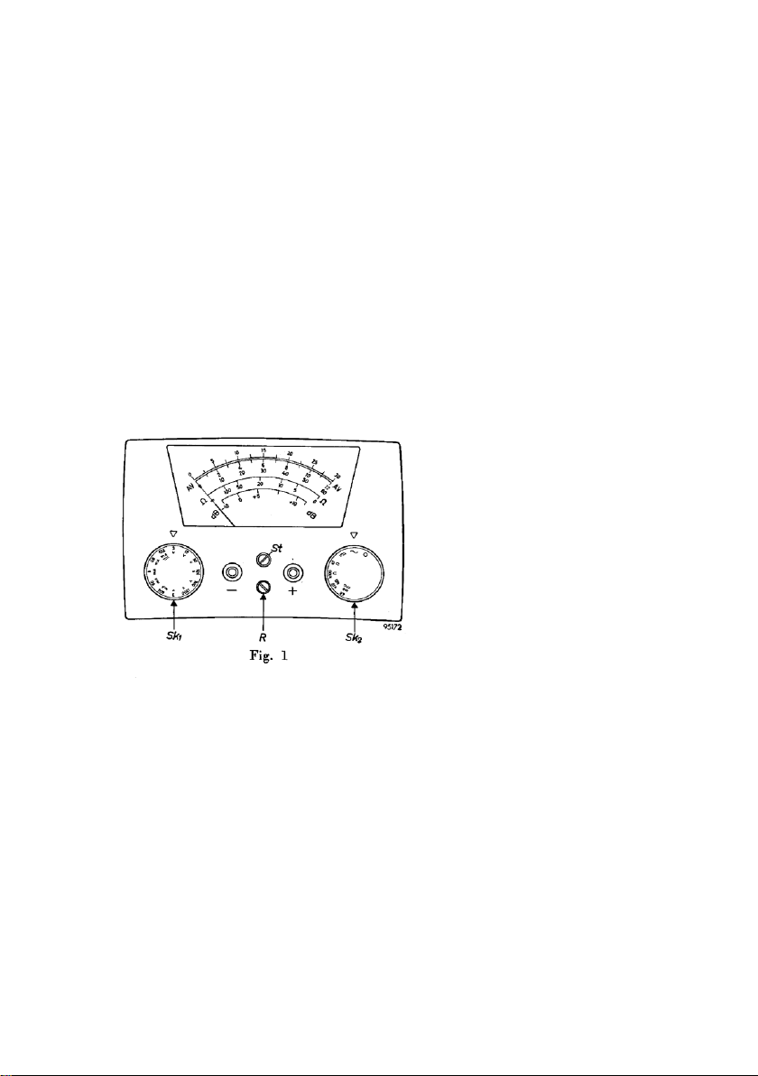
OPERATION 5
Zero Setting 5
Measuring 6
A. Direct voltage 6
B. Direct Current 6
C. Alternating voltage 7
D. Alternating Current 7
E. Resistance 7
Db-Scale 7
REPLACEMENT OF BATTERIES 8
SOME EXAMPLES OF MEASUREMENTS 8
A’. Direct-voltage measurements 8
B’. D.C. Measurements 8
C’. A.C. Measurements 9
METER CIRCUITS FOR THE VARIOUS MEASURING
RANGES 9
CIRCUIT DIAGRAMS 10
RECOMMENDED BATTERIES 11
3
APPLICATIONS
PROTECTION
For all commonly used
measuring ranges the
galvanometer can stand
overloading for a short
time. This does not hold,,
however, if the knob Sk2 is
set to the very sensitive
position "60mV"; in this
position the protection is
cut out and the meter
cannot stand overload any
longer. The maximum
current is 30 µA.
Between 50 and 70%of all electrical faults occurring in a radio receiver or
amplifier are such that they can he easily traced by measurements, for
which particularly the PHILIPS Universal Measuring Instrument P 817
00/01 is eminently suitable.
It is the ideal measuring instrument for use in the smaller repair shops or at
the customer's home, owing to its small dimensions and to the fact it does
not require any mains supply.
The following measurements can be carried out with the meter:
a. direct and alternating voltages from 0 to 1200 V;
b. direct and alternating currents from 0 to 3 A;
c. resistances from 0 to 10 MΩ
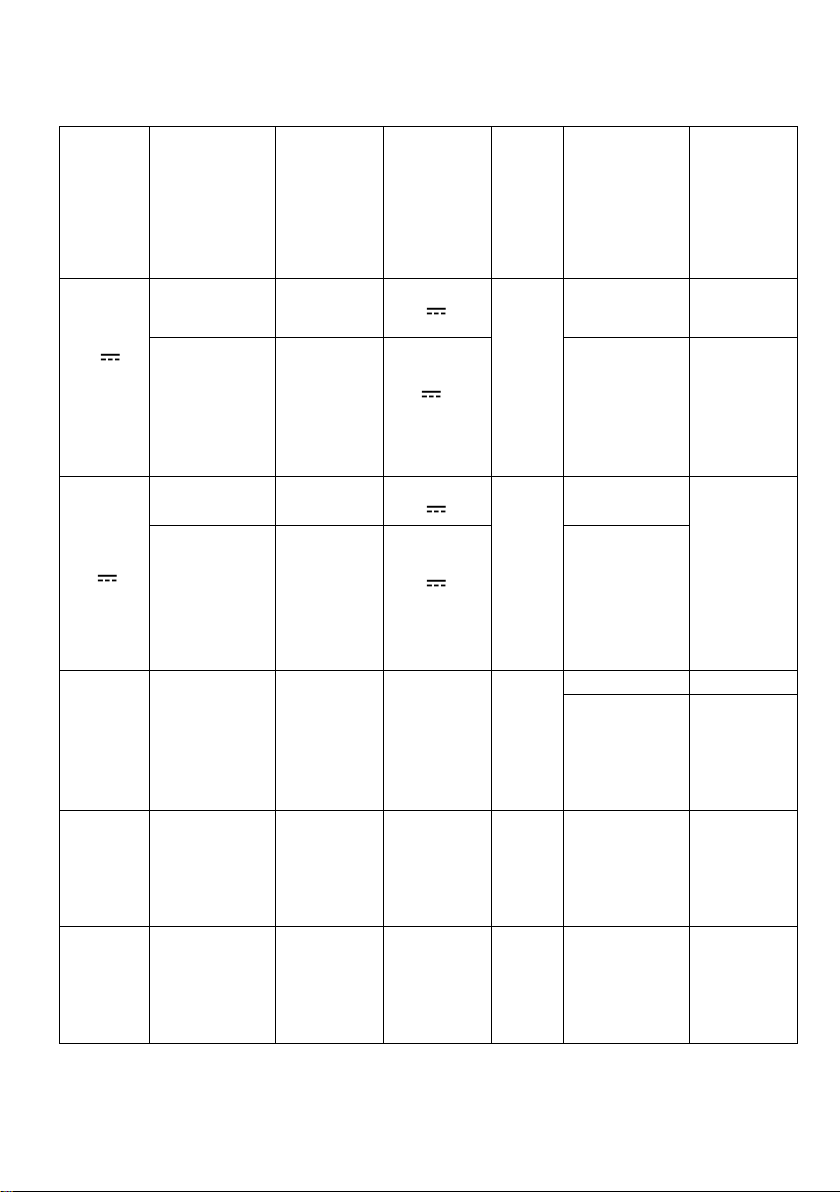
ELECTRICAL DATA
The voltage loss and the current consumption as given in the table at page 4
apply to full deflection; at less deflection these values are proportionally
lower. All current and voltage scales are linear. For alternating-current and
alternating-voltage measurements the reading remains accurate throughout
the frequency range 30 10,000 c/s, with the exception of the measuring
range of 1200 V, for which the upper accuracy limit lies at 5,000 c/s.
The A.C. and alternating-voltage ranges have been calibrated for a purely
sinusoidal signal. Although the meter can, if necessary, be used standing
upright, it measures more accurately lying down (see also page 5, under
"zero setting").
4
Measurement
Measuring
range
Position
Of Sk1
Position
Of Sk2
Scale
Current
consumption
or voltage
loss at full
deflection
Sensitivity
V
0 – 60 mV
Any
position
60 mV *
AV
33,300
Ω/V
0 – 3 V
0 – 12 V
0 – 30 V
0 – 120 V
0 – 300 V
0 -1200 V
3 V
12 V
30 V
120 V
300 V
1200 V
30 µA
25 µA
40,000
Ω/V
I
0 – 30 µA
Any
position
60 mV *
AV
60 mV
0 – 120 µA
0 – 600 µA
0 – 6 mA
0 – 60 mA
0 – 600 Ma
0 – 3 A
0.12 mA
0.6 mA
6 mA
60 mA
600 mA
3 A
285 mV
345 mV
360 mV
360 mV
400 mV
580 mV
V ~
0 –3V
0 – 12 V
0 – 30 V
0 – 120 V
0 – 300 V
0 – 1200 V
3 V
12 V
30 V
120 V
300 V
1200 V
~
AV
5 Ma
600 µA
1666 Ω/V
I ~
0 - 600 µA
0 – 6 mA
0 – 60 mA
0 – 600 mA
0 – 3 A
0.6 mA
6 mA
60 mA
600 mA
3 A
~
AV
R
0 – 1000 Ω
0 – 100 kΩ
0 – 10 MΩ
Any
position
X 1 Ω
X 100 Ω
X 10 kΩ
Ω
83 mA
0.8 mA
0.a3 mA
Centre-scale
Value
18 Ω
1800 Ω
180,000 Ω
 Loading...