

Philips P2HD AG-HPX170P User Manual
This product is eligible for the P2HD
5 Year Warranty Repair Program. For
details, see page 5.
Before useDescription of
Operating Instructions
Memory Card Camera-Recorder
Model No. AG-HPX170P
parts
PreparationShootingPlaybackEditingDisplaysMenuReference
Before operating this product, please read the instructions carefully and save this
manual for future use.
F0808T0 -P
Printed in Japan
D
ENGLISH
VQT1U92
2
Read this rst!
indicates safety information.
CAUTION
RISK OF ELECTRIC SHOCK
DO NOT OPEN
CAUTION: TO REDUCE THE RISK OF ELECTRIC
SHOCK, DO NOT REMOVE COVER (OR BACK).
NO USER-SERVICEABLE PARTS INSIDE.
REFER TO SERVICING TO QUALIFIED SERVICE
PERSONNEL.
The lightning ash with arrowhead symbol,
within an equilateral triangle, is intended to
alert the user to the presence of uninsulated
“dangerous voltage” within the product’s
enclosure that may be of sufcient magnitude
to constitute a risk of electric shock to
persons.
The exclamation point within an equilateral
triangle is intended to alert the user to
the presence of important operating and
maintenance (servicing) instructions in the
literature accompanying the appliance.
WARNING:
•
TO REDUCE THE RISK OF FIRE OR SHOCK
HAZARD, DO NOT EXPOSE THIS EQUIPMENT
TO RAIN OR MOISTURE.
•
TO REDUCE THE RISK OF FIRE OR SHOCK
HAZARD, KEEP THIS EQUIPMENT AWAY
FROM ALL LIQUIDS. USE AND STORE ONLY
IN LOCATIONS WHICH ARE NOT EXPOSED
TO THE RISK OF DRIPPING OR SPLASHING
LIQUIDS, AND DO NOT PLACE ANY LIQUID
CONTAINERS ON TOP OF THE EQUIPMENT.
WARNING:
Always keep memory cards or accessories (coin
battery, microphone holder screws, microphone
holder adapter, ferrite cores, INPUT terminal cover)
out of the reach of babies and small children.
CAUTION:
TO REDUCE THE RISK OF FIRE OR SHOCK
HAZARD AND ANNOYING INTERFERENCE, USE
THE RECOMMENDED ACCESSORIES ONLY.
CAUTION:
Do not jar, swing, or shake the unit by its handle
while the conversion lens or another accessory is
attached.
Due to the added weight of the conversion lens, any
strong jolt to the handle may damage the unit or
result in personal injury.
CAUTION:
Danger of explosion or re if battery is
mistreated.
For Battery Pack
• Replace only with same or specied type.
• Do not disassemble or dispose of in re.
•
Do not store in temperatures over 60°C (140°F).
•
Do not leave the battery in an automobile
exposed to direct sunlight for a long period of
time with doors and windows closed.
• Use specied charger.
For Battery of Remote Controller
• Replace battery with part No. CR2025 only.
• Do not recharge the battery.
• Do not disassemble or dispose of in re.
•
Do not store in temperatures over 60°C (140°F).
Camera-Recorder
The rating plate is on the underside of the
viewnder.
AC Adapter
The rating plate is on the underside of the AC
Adapter.
Disconnect the AC mains plug from the AC
mains socket when not in use.
CAUTION:
In order to maintain adequate ventilation, do
not install or place this unit in a bookcase,
built-in cabinet or any other conned space. To
prevent risk of electric shock or re hazard due
to overheating, ensure that curtains and any
other materials do not obstruct the ventilation.
CAUTION:
Do not lift the unit by its handle while the
tripod is attached. When the tripod is attached,
its weight will also affect the unit’s handle,
possibly causing the handle to break and
hurting the user. To carry the unit while the
tripod is attached, take hold of the tripod.
CAUTION:
EXCESSIVE SOUND PRESSURE FROM
EARPHONES AND HEADPHONES CAN
CAUSE HEARING LOSS.
CAUTION:
THE MAINS PLUG OF THE POWER SUPPLY
CORD SHALL REMAIN READILY OPERABLE.
THE AC RECEPTACLE (MAINS SOCKET OUTLET)
SHALL BE INSTALLED NEAR THE EQUIPMENT
AND SHALL BE EASILY ACCESSIBLE.
TO COMPLETELY DISCONNECT THIS
EQUIPMENT FROM THE AC MAINS,
DISCONNECT THE POWER CORD PLUG FROM
THE AC RECEPTACLE.
CAUTION:
Do not leave the unit in direct contact with the
skin for long periods of time when in use.
Low temperature burn injuries may be suffered if
the high temperature parts of this unit are in direct
contact with the skin for long periods of time.
When using the equipment for long periods of
time, make use of the tripod.

indicates safety information.
FCC NOTICE (USA)
Declaration of Conformity
Model Number: AG-HPX170P
Trade Name: PANASONIC
Responsible Party: Panasonic Corporation of North America One Panasonic Way, Secaucus, NJ
Support contact: Panasonic Broadcast & Television Systems Company 1-800-524-1448
This device complies with Part 15 of FCC Rules.
Operation is subject to the following two conditions:
(1) This device may not cause harmful interference, and (2) this device must accept any
interference received, including interference that may cause undesired operation.
To assure continued compliance, follow the attached installation instructions and do not make any
unauthorized modications.
07094
CAUTION:
This equipment has been tested and found to comply with the limits for a Class B digital device,
pursuant to Part 15 of the FCC Rules. These limits are designed to provide reasonable protection
against harmful interference in a residential installation. This equipment generates, uses and can
radiate radio frequency energy and, if not installed and used in accordance with the instructions,
may cause harmful interference to radio communications. However, there is no guarantee that
interference will not occur in a particular installation. If this equipment does cause harmful
interference to radio or television reception, which can be determined by turning the equipment off
and on, the user is encouraged to try to correct the interference by one of the following measures:
• Reorient or relocate the receiving antenna.
• Increase the separation between the equipment and receiver.
• Connect the equipment into an outlet on a circuit different from that to which the receiver is
connected.
• Consult the dealer or an experienced radio/TV technician for help.
The user may nd the booklet “Something About Interference”
available from FCC local regional ofces helpful.
FCC Warning:
To assure continued FCC emission limit compliance, follow the attached installation instructions
and the user must use only shielded interface cables when connecting to host computer or
peripheral devices. Also, any unauthorized changes or modications to this equipment could void
the user’s authority to operate this device.
NOTIFICATION (Canada)
This class B digital apparatus complies with Canadian ICES-003.
Cet appareil numéique de la classe B est conforme à la norme NMB-003 du Canada.
IMPORTANT
“Unauthorized recording of copyrighted television programs, video tapes and other materials may infringe the
right of copyright owners and be contrary to copyright laws.”
A lithium ion/polymer battery that is recyclable powers the product you have purchased.
Please call 1-800-8-BATTERY for information on how to recycle this battery.
For USA-California Only
This product contains a CR Coin Cell Lithium Battery which contains Perchlorate Material – special
handling may apply.
See www.dtsc.ca.gov/hazardouswaste/perchlorate.
3

4
IMPORTANT SAFETY INSTRUCTIONS
1) Read these instructions.
2) Keep these instructions.
3) Heed all warnings.
4) Follow all instructions.
5) Do not use this apparatus near water.
6) Clean only with dry cloth.
7) Do not block any ventilation openings. Install in accordance with the manufacturer’s instructions.
8) Do not install near any heat sources such as radiators, heat registers, stoves, or other apparatus
(including ampliers) that produce heat.
9) Do not defeat the safety purpose of the polarized or grounding-type plug. A polarized plug has two
blades with one wider than the other. A grounding-type plug has two blades and a third grounding
prong. The wide blade or the third prong are provided for your safety. If the provided plug does not t
into your outlet, consult an electrician for replacement of the obsolete outlet.
10) Protect the power cord from being walked on or pinched particularly at plugs, convenience
receptacles, and the point where they exit from the apparatus.
11) Only use attachments/accessories specied by the manufacturer.
12) Use only with the cart, stand, tripod, bracket, or table specied by the manufacturer, or
sold with the apparatus. When a cart is used, use caution when moving the cart/
apparatus combination to avoid injury from tip-over.
13) Unplug this apparatus during lightning storms or when unused for long periods of time.
14) Refer all servicing to qualied service personnel. Servicing is required when the
apparatus has been damaged in any way, such as power-supply cord or plug is
damaged, liquid has been spilled or objects have fallen into the apparatus, the apparatus has been
exposed to rain or moisture, does not operate normally, or has been dropped.
Recommendation for Use of Genuine Panasonic Battery Pack (Rechargeable Battery)
Thank you for using a Panasonic product.
It has been our policy to recommend that the genuine Panasonic battery pack be used for any
Panasonic product that uses a battery pack, including digital cameras. It has, however, been found that
imitation battery packs that look very similar to the genuine Panasonic battery pack are marketed in
some markets.
Some of these imitation battery packs are not equipped with any protective devices that meet given
quality standards for permitting use at high power outputs and for long hours.
If any of these battery packs of inferior quality is used, it could lead to an accident or failure
involving ring or explosion.
To ensure that our products are used in utmost safety, we once again remind you that we recommend
the use of a genuine Panasonic battery pack for any Panasonic product that is to use a battery pack.
The genuine Panasonic battery packs are sold under our stringent quality control.
Please be advised that we are not liable for any accident or failure occurring as a result of use of an
imitation battery pack.
We appreciate your kind understanding and cooperation in this regard.
Software information for this product
1. Customer advisory: This product includes software licensed under the GNU General Public License
(GPL) and GNU Lesser General Public License (LGPL); customers have the right to download, modify,
and redistribute source code for this software.
Descriptions of the GPL and LGPL are stored on the installation CD included with this camera-recorder.
See the folder named \LDOC. (The description is the original (written in English).) To download the
relevant source code, visit https://eww.pavc.panasonic.co.jp/pro-av/
Please note that we cannot answer any questions you may have about the content, etc. of any source
code you may obtain from the above Web site.
2. This product includes software licensed under the MIT License. A description of the MIT is stored on
the installation CD included with this camera-recorder. See the folder named \LDOC. (The description is
the original (written in English).)
• LEICA is a trademark of Leica Microsystems IRGmbH.
• DICOMAR is a trademark of Leica Camera AG.
• SD logo is a trademark.
All other explanations, company names, and product names are the registered trademarks of the
respective companies.
Thank you for purchasing this Panasonic P2HD device.
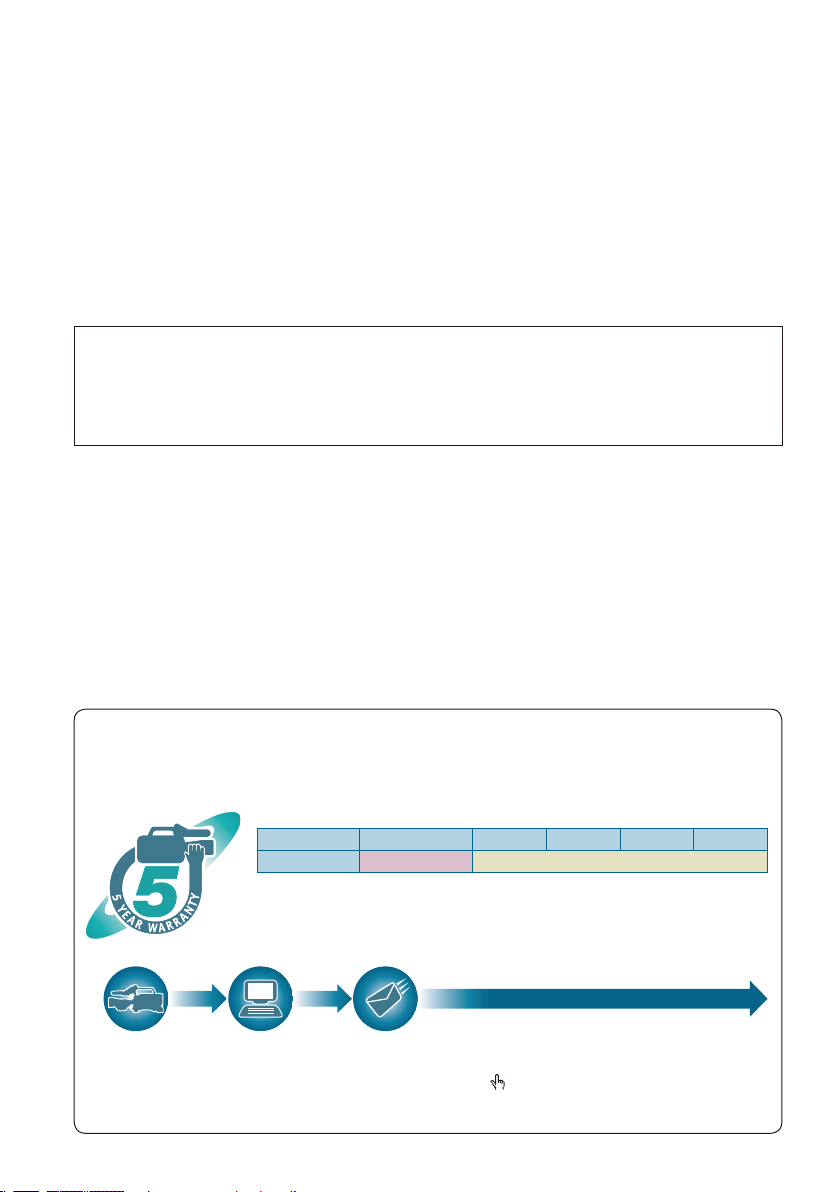
P2HD 5 Year Warranty Repair Program
Register as a user for this device to receive a special service warranty up to ve years of free warranty
repairs.
Customers who register as users on the website will receive a extended warranty repair
valid for up to ve years.
1st year 2nd year 3rd year 4th year 5th year
P2HD device*2Basic warranty
*1: Please note that this extended warranty is not available in some countries/regions see web
site below for details. *2: Not all models eligible for extended warranty coverage. *3: The basic
warranty period may vary depending on the country/region see enclosed warranty for warranty
coverage. *4: Not all repair work is covered by this extended warranty see enclosed warranty
card for warranty coverage. *5: The maximum warranty period may be adjusted depending on
the number of hours the device has been used.
*3
*1
Extended warranty repair
*4
Free 5 years of Warranty Repairs
Purchase
P2 product
Details about user registration and the extended warranty:
Please note, this is a site that is not maintained by Panasonic Canada Inc. The Panasonic Canada Inc. privacy policy does not
apply and is not applicable in relation to any information submitted. This link is provided to you for convenience.
Register online
within 1 month
“Registration Notice”
e-mail sent
Make sure to save the “Registration Notice”
e-mail during the warranty period.
http://panasonic.biz/sav/pass_e
*5
5

Contents
Read this rst! ..................................................... 2
IMPORTANT SAFETY INSTRUCTIONS .............. 4
Recommendation for Use of Genuine
Panasonic Battery Pack
(Rechargeable Battery) ................................... 4
Software information for this product ............... 5
Before use
Outline of operations .......................................... 8
Precaution for use ............................................... 9
Accessories ....................................................... 10
Optional units .................................................... 10
About this manual ............................................. 10
Description of parts
Description of parts .......................................... 11
Right side and rear side .................................. 11
Left side ........................................................... 12
Terminals and mounting parts ......................... 13
Remote control ................................................ 14
Preparation
The battery ......................................................... 15
Charging .......................................................... 15
Installing and removing the power supply ...... 16
Installing and removing the battery ................. 16
Connecting and disconnecting
the power cord ............................................. 16
Adjusting the hand strap .................................. 17
Attaching the shoulder strap ............................ 17
Detaching and attaching the lens hood .......... 17
The remote control ............................................ 18
Insert the battery ............................................. 18
Remote control setup ...................................... 18
Turn on/off the camera ...................................... 19
Tally lamp ........................................................... 19
Viewnder .......................................................... 20
Using the viewnder ........................................ 20
Using the LCD ................................................. 21
Emphasizing outlines ...................................... 21
Adjusting the screen display ............................ 22
Adjusting the backlight ..................................... 23
Flipping images vertically and horizontally ...... 23
Switching between overscan and
underscan .................................................... 23
Setting the calendar .......................................... 24
Shooting
Basic shooting operations ............................... 25
Preparing to shoot ........................................... 25
Shooting in auto mode .................................... 25
Checking photos taken (REC CHECK) ........... 26
6
P2 card access lamps ..................................... 26
Protecting against a possible erasure ............. 26
Formatting P2 cards ........................................ 26
Recording times .............................................. 27
Remove the P2 card ........................................ 28
Using SD/SDHC memory cards ........................ 29
Installing and removing
the SD memory card ................................... 29
Formatting SD memory card ........................... 29
Cautions in using SD memory cards ............... 29
Using the zoom function ................................... 30
Digital zoom function ....................................... 30
Variable frame rates (VFR) ................................ 31
Native recording .............................................. 32
Standard recording .......................................... 32
Using variable frame rates (VFR) .................... 33
Shooting in 1080i/480i progressive mode ....... 34
Shooting in manual mode ................................. 35
Switching to manual mode .............................. 35
Manual focusing .............................................. 35
Using focus assist ............................................ 36
Iris adjustments ............................................... 36
Adjusting the gain ............................................ 37
Light intensity adjustments .............................. 37
Adjusting the white balance ............................. 38
Black balance adjustments .............................. 39
Auto Tracking White (ATW) .............................. 39
Shooting techniques for different targets ....... 40
Low-angle shooting ......................................... 40
Self-portrait shooting ....................................... 40
Zebra pattern ................................................... 40
Marker ............................................................. 40
Checking and displaying shooting status ........ 41
Changing the image size ................................. 41
Optical Image Stabilizer................................... 42
Adding effects to images ................................. 42
Using the USER buttons .................................. 42
Backlight compensation ................................... 42
Color bars ........................................................ 42
Waveform monitor function .............................. 43
Adjusting the volume while shooting ............... 43
Backup recording ............................................. 43
2-slot continuous recording ............................. 44
Shot mark function .......................................... 44
Text memo recording ....................................... 44
Time stamp function ........................................ 44
LAST CLIP DELETE function .......................... 45
Using the special recording functions ............ 46
Pre-recording (PRE REC) ............................... 46
Interval recording (INTERVAL REC) ................ 46
One-shot recording (ONE-SHOT REC) ........... 47
Loop recording (LOOP REC) .......................... 47
Adjusting the shutter speed ............................. 49

Synchro scan ................................................... 50
Switching Audio Input ....................................... 51
Using the built-in microphone .......................... 51
Using another microphone and
audio equipment .......................................... 51
Adjusting the recording level ........................... 52
Using scene les ............................................... 53
Changing scene le settings ........................... 53
Saving scene les and other settings on
SD memory cards .......................................... 55
Clip metadata ..................................................... 57
Using the Counter ............................................. 58
Counter display ................................................ 58
1394TC preset mode ....................................... 58
Charging the built-in battery/
Setting the time data ..................................... 59
Recharging the built-in battery ........................ 59
Setting the time code ....................................... 59
Specifying the time code (TC PRESET) .......... 59
Setting user information................................... 61
Playback
Basic playback operations ............................... 63
Thumbnail screen .............................................. 64
Basic thumbnail screen operations.................. 64
Adding shot marks to clips .............................. 66
Clearing the thumbnail screen ......................... 66
Direct shooting functions ................................. 66
Thumbnail operations ....................................... 67
Selecting the thumbnail display method
(THUMBNAIL) ............................................. 67
Deleting clips and formatting cards
(OPERATION) ............................................. 68
Checking the clip or card information
(PROPERTY) .............................................. 69
Editing the recorded clip metadata .................. 71
Uploading the metadata (META DATA) ............ 72
Useful playback functions ................................ 74
Variable speed search ..................................... 74
Slow playback .................................................. 74
Fast forward/rewind playback .......................... 74
Frame-by-frame playback ................................ 74
Clip skip ........................................................... 75
Adjusting the volume ....................................... 75
Viewing images on a monitor .......................... 75
Checking the date and time ............................. 75
Editing
Connecting external units ................................ 76
Headphones .................................................... 76
External microphone ....................................... 76
Computer (non-linear editing/le transfer) ....... 77
Hard disk drive (data copying) ......................... 78
Digital video equipment (Dubbing) .................. 79
Video deck (Dubbing) ...................................... 80
TV/Monitor (playback/dubbing) ........................ 80
Nonlinear editing with P2 card (PC mode) ...... 81
Copying from P2 cards to the hard disk drive
(1394 HOST mode) ........................................ 83
Warnings ......................................................... 85
Dubbing .............................................................. 86
Digital input/output ........................................... 86
Analog output .................................................. 86
Displays
Screen displays ................................................. 87
Regular displays .............................................. 87
Warnings ......................................................... 91
Setting the DISPLAY items .............................. 93
Menu
Using the setup menus ..................................... 94
Using the menus.............................................. 94
Initializing the menu settings ........................... 95
Setup menu structure ....................................... 96
CAM (camera) mode menu ............................. 96
MCR (playback) mode menu ........................... 97
Setup menu list .................................................. 98
SCENE FILE screen ........................................ 98
CAMERA SETUP screen .............................. 100
SW MODE screen ......................................... 101
AUTO SW screen .......................................... 103
RECORDING SETUP screen ........................ 104
PLAYBACK FUNCTIONS screen .................. 107
AV IN/OUT SETUP screen ............................ 107
DISPLAY SETUP screen ............................... 108
CARD FUNCTIONS screen........................... 109
OTHER FUNCTIONS screen ........................ 110
OPTION MENU screen ................................. 112
Reference
Before calling for service ................................ 113
Operating precautions .................................... 116
Updating the driver in the camera ................. 118
Cleaning ........................................................... 119
Storage Precautions ........................................ 120
How to handle data recorded on P2 cards .... 121
Checkpoints for using memory cards ........... 122
Recording format list....................................... 123
Appendix .......................................................... 124
Specications .................................................. 125
7
8
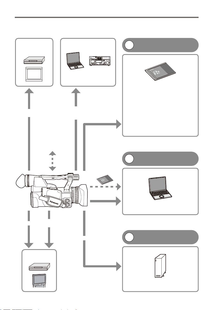
Outline of operations
This unit is compatible with P2 (Professional Plug-in) cards.
The P2 card has a large capacity with a high transfer rate, and allows you sophisticated movie-making on
this handy camera, including HD (High Denition) recording and smooth editing/dubbing.
Video
equipment/
Monitor
BNC cable
(HD-SDI)
The setting values
such as the user le
are saved to and read
from the SD memory
card.
Computer/
Memory card recorder
The contents can be transferred
as a data stream (digital
dubbing).
IEEE1394
(Windows/
Macintosh)
P2 card
P2 mode shooting and
1
playback (Pages 25 and 63)
P2 card
You can use the following features:
HD (High Denition) recording
•
Multi format recording
•
Variable frame rates
•
Slow & quick motion recording
Maximum 4 channel uncompressed
•
digital audio recording
DV recording (480i)
•
For details on how to handle recorded
data, see page 121
PC mode (Page 81)
2
Computer
The data (le) is transferred for nonlinear
editing on your computer or other unit.
1394 host mode (Page 83)
3
External hard disk
AV cable
Component
video cable
Video equipment/
USB2.0
(Windows)
IEEE1394
(Macintosh)
IEEE1394 (SBP-2*)
Television
The unit directly controls the external hard disk
*Serial Bus Protocol-2
drive, and transfers the data (le) to it.

Precaution for use
Always take some trial shots before actual shooting.
When shooting important events (such as weddings), always take some trial shots and check that the
•
sound and images have been recorded properly before actual shooting.
Be sure to check and set the calendar and time zone.
These settings affect the control and playback sequence of the recorded contents. Before making a
•
recording, set and check the calendar and time zone. (Page 24)
Panasonic makes no guarantees for your recordings.
Please understand that Panasonic makes no guarantees for your recordings in cases where images
•
and/or sound were not recorded as you intended due to problems with the camera-recorder.
Respect copyrights
Copyright laws forbid the use of video and audio material you have recorded for any purpose other than
•
your own personal enjoyment. Remember that restrictions apply to the shooting of cer tain material even if
it is intended for private use.
Caution regarding laser beams
The CCD may be damaged if it is subjected to light from a laser beam.
•
When using the camera-recorder in locations where laser irradiation equipment is used, be careful not to
allow the laser beam to shine directly on the lens.
Notes when connecting a 1394 cable
Windows:
•
Before connecting, turn off the main unit power, and check the shape and orientation of the terminal.
Macintosh:
•
After turning on the power of the Apple Macintosh computer, check the shape and orientation of the
terminal, and then connect the cable.
(Pages 77, 78)
Media that can be used in this unit
The following media can be used in this unit. For details, refer to the respective pages.
P2 card (Pages 25, 121)
•
SD/SDHC memory cards (Pages 29, 122)
•
Mounting the camera-recorder on a tripod
The tripod mounting hole is 5.5 mm deep. Do not force the tripod screw beyond this depth.
You can damage the camera-recorder if you use any screw other than 1/4-20UNC.
Before use
For other usage notes, see page 116.
Attach the tripod to the tripod hole.
9
10
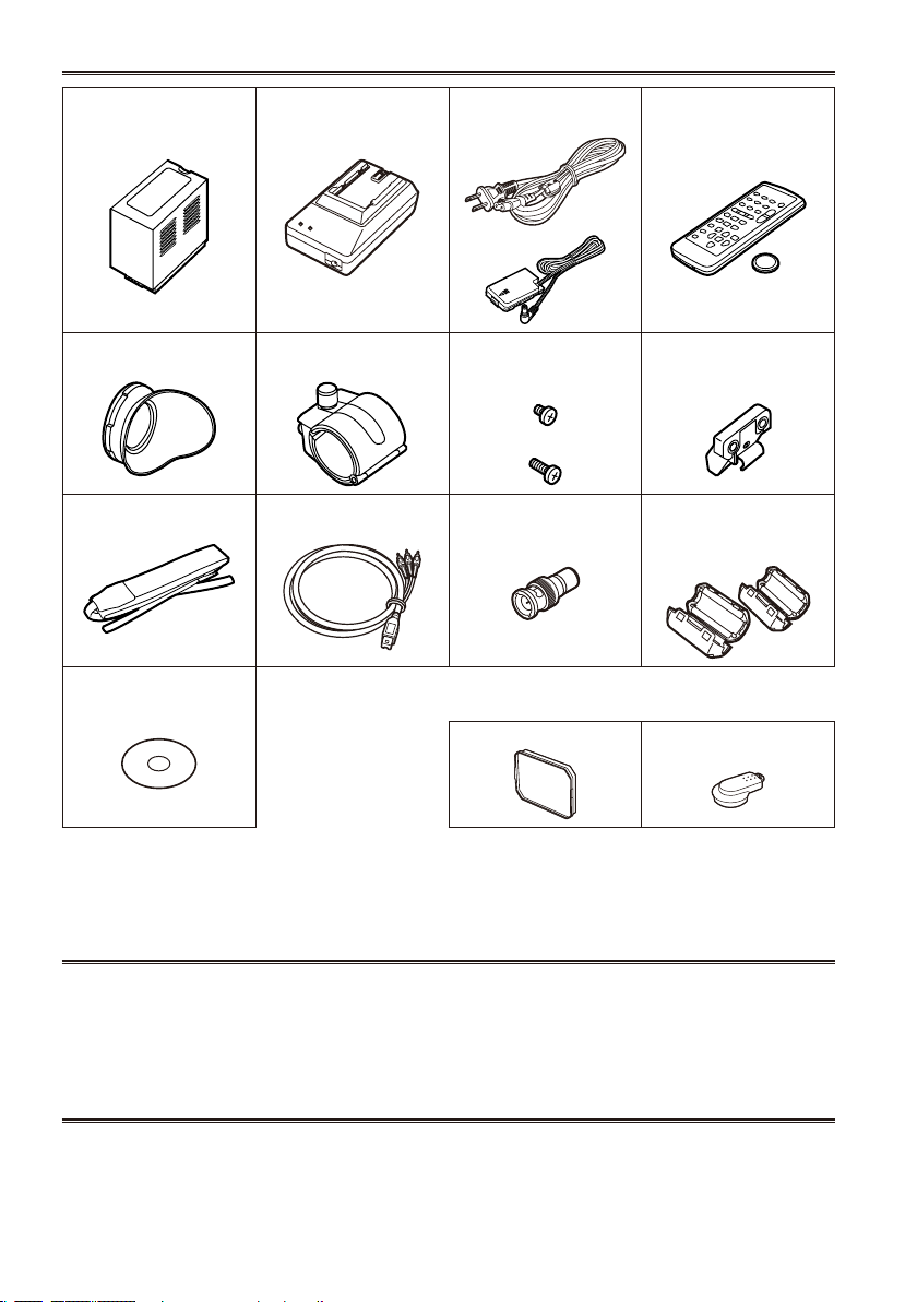
Accessories
Battery *1 AC Adapter AC power supply cord/
DC cord
Eye cup Microphone holder Screws for microphone
holder
6-mm screws (2)
12-mm screws (2)
Shoulder belt Component video cable PIN-BNC conversion
plugs (3)
CD-ROM The following accessories are attached to the
camera-recorder.
Lens hood INPUT terminal cover (2)
Wireless remote control
and battery (CR2025)
Microphone holder
adapter
30-mm ferrite core (2)*2
35-mm ferrite core (2)*2
*1 For part numbers for the battery, see “Optional units”. (see below)
*2 When using a 1394 cable (sold separately) or a USB cable (sold separately), attach ferrite cores to the
both ends of the cable. (Page 77)
Optional units
XLR microphone
•
AG-MC200G
Battery
•
CGA-D54 (5400 mAh: equivalent to accessory battery)
About this manual
Note concerning illustrations in these instructions
Illustrations (camera-recorder, menu screens, etc.) in these operating instructions differ slightly from the
•
actual camera-recorder.
References
References are shown as (Page @).
•
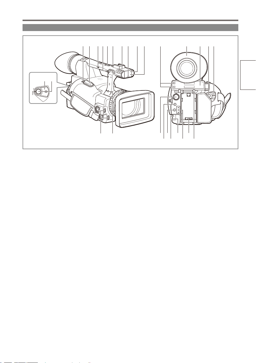
Description of parts
POWER
ON
OFF
Right side and rear side
3 4 5 7 8 9 10 11 12
6
1 2
13
14
1 POWER switch (Page 19)
2 START/STOP button (Page 25)
3 REC CHECK button (Page 25)
4 Zoom button (Page 30)
5 HANDLE ZOOM switch (Page 30)
6 Recording enable/disable switch (Page 40)
7 Handle zoom button (Page 30)
8 Handle START/STOP button (Page 25)
9 Built-in stereo microphone (Page 51)
10 Tally lamp (Front) (Page 19)
11 Remote control sensor (Front) (Page 18)
12 White balance sensor (Page 39)
12171615
18 202122
19
13 INPUT 1/2 (audio input) switch (Page 51)
14 Zoom ring pin hole (Page 30)
15 P2 card access lamp (x 2) (Page 26)
16 Viewnder (Page 20)
17 P2 card/SD memory card slot (cover)
(Pages 25 and 29)
18 SCENE FILE dial (Page 53)
19 SLOT SEL button (Page 44)
20 Mode button (Page 25)
21 Remote control sensor (Rear) (Page 18)
22 Tally lamp (Rear) (Page 19)
23 Mode lamp (Page 25)
24 Power terminal (Page 16)
25 Battery release button (Page 16)
24
23 25
parts
Description of
11
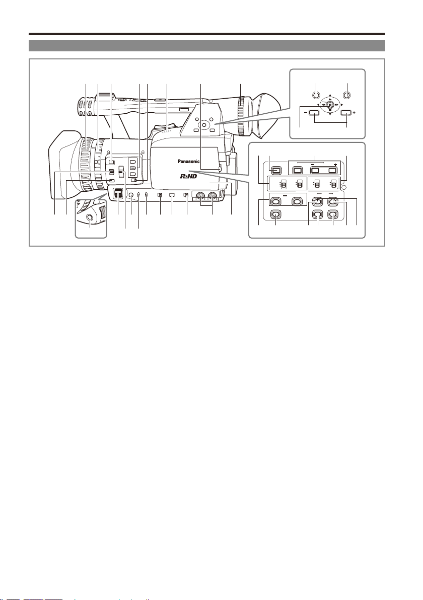
Description of parts (continued)
BARS
CH1 SELECT
COUNTER RESET/TC SET
REC
CH2 SELECT
AUDIO
INT(L)
INPUT1
INPUT2
SHUTTER
SPEES SELECT
INT(R)
INPUT2
INPUT1
MIC POWER+48V
ON
OFF
INPUT2
ON
OFF
LCD
ZEBRA
EVF DTL
OIS
WFM
MENU
PUSH-SET
PAGE/AUDIO MON/VAR
THUMBNAIL
AWB
Left side
3 4 652
1
11
12
14 161517 18 19 2010 21
13
9
1 Focus ring (Page 35)
2 Zoom ring (Page 30)
If you don’t need the zoom ring pin, t it
into the provided zoom ring pin hole (14 on
page 11) so that you don’t loose it.
3 FOCUS ASSIST button (Page 36)
4 USER button (Page 42)
5 ZOOM switch (Page 30)
6 Built-in speaker (Page 75)
7 OPEN button (Page 21)
8 Diopter adjustment dial (Page 20)
9 FOCUS switch (Page 35)
10 PUSH AUTO button (Page 35)
11 AWB button (Page 38)
12 IRIS dial (Page 36)
13 ND FILTER switch (Page 37)
14 IRIS button (Page 36)
15 GAIN switch (Page 37)
16 WHITE BAL switch (Page 38)
17 FUCUS RING (FOCUS/IRIS) switch
(Page 35)
18 DISP/MODE CHK button (Page 41)
12
7
8
22 23
24 25
27
26 2928
33 34
32 353130
19 AUTO/MANUAL switch (Page 25)
20 AUDIO LEVEL knobs (CH1, CH2) (Page 52)
21 LCD monitor (Page 21)
22 MENU button (Page 94)
23 THUMBNAIL button (Page 66)
24 Operation lever (Pages 63 and 94)
25 PAGE/AUDIO MON/VAR button (Pages 43
and 74)
26 CH1, CH2 SELECT switch (Page 51)
27 BARS button (Page 42)
28 SHUTTER, SPEED SELLECT +/- button
(Page 49)
29 INPUT1, 2 switch (MIC POWER +48 V)
(Page 51)
30 COUNTER - RESET/TC SET button
(Page 58)
31 LCD button (Page 23)
32 ZEBRA button (Page 40)
33 EVF DTL button (Page 21)
34 WFM button (Page 43)
35 OIS button (Page 42)
36 MCR REC button (Page 86)
Functions when the ZEBRA button (32) and
OIS button (35) are pressed at the same time.
36
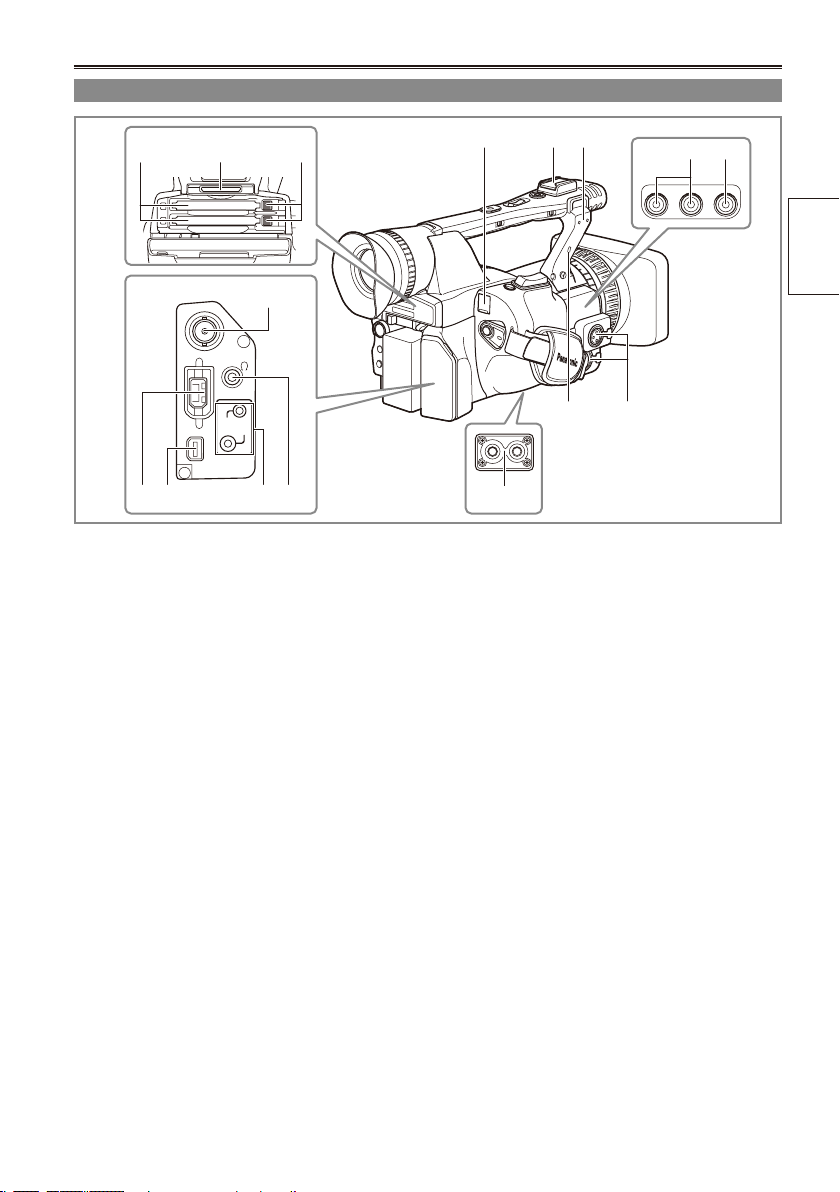
Terminals and mounting parts
SDI
OUT
1394
CAM REMOTE
FOCUS IRIS
ZOOM S/S
COMPONENT
OUT
54 6
7
1098 11
1 USB terminal (Mini-B) (Page 77)
2 Light shoe
3 Microphone shoe (Page 76)
4 P2 card slots (Page 25)
5 SD memory card slot (Page 29)
6 P2 card eject buttons (Page 28)
7 SDI OUT terminal (Page 80)
8 1394 terminal (Pages 77 and 78)
9 COMPONENT OUT terminal (Page 80)
10 CAM REMOTE jack*
FOCUS/IRIS (3.5 mm mini jack)
You can connect a remote control unit to
control the FOCUS and IRIS (aperture).
ZOOM S/S (2.5 mm super mini jack)
You can connect a remote control unit to
control zoom and start/stop of recording.
11 Headphone jack (3.5 mm stereo mini jack)
(Page 76)
12 Tripod hole (Page 9)
1 2 3
13
14
1615
12
13 Security Lock opening
Use this opening to attach a security cable.
For details on how to attach the cable, see the
Operating Instructions supplied with the cable.
The security lock and security cable are
designed to prevent theft, but Panasonic will
not accept any liability for damages resulting
from theft.
14 INPUT 1/2 terminal (XLR, 3 pin) (Page 76)
15 AUDIO OUT CH1/CH2 terminals (Page 80)
16 VIDEO OUT terminal (Page 80)
parts
Description of
* Do not connect any equipment except the remote
controller to the CAM REMOTE jack.
Connecting any equipment other than the remote
control may cause the image brightness to
change and/or the images to appear out of focus.
13
Description of parts (continued)
OSD
COUNTER
RESET TITLE
STILL ADV
PAUSE
STILL ADV
INDEX
SELECT
STORE
OFF/ON
P.B.DIGITAL
VAR.
SEARCH
VOL +
-
PB.
ZOOM
MENU
SET
ITEM
STOP INDEX
MULTI/
P-IN-P
REC A.DUB
PLAY/REW FF/
ZOOM
DATE/
TIME
PHOTO
SHOT
START/
STOP
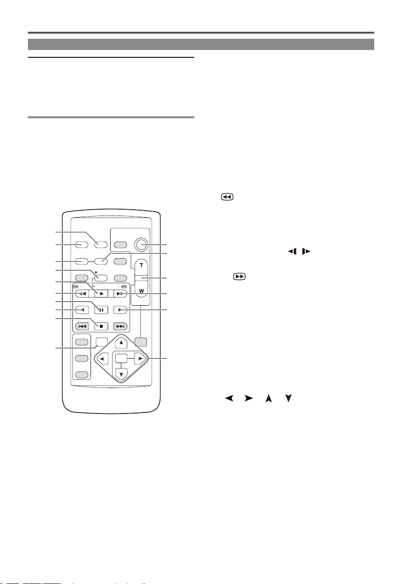
Remote control
The following buttons are for functions that
cannot be executed on the camera-recorder.
• PHOTO SHOT • TITLE • A.DUB
• MULTI/P-IN-P • SELECT
• STORE • OFF/ON
• PB.ZOOM • INDEX
1
2
3
5
6
7
8
9
10
14
12
13
11
15
1 DATE/TIME button (Page 75)
2 OSD button (Page 75)
3 COUNTER button (Page 58)
Same function as the COUNTER button on the
main unit.
4 COUNTER RESET button (Page 58)
Same function as the COUNTER RESET
button on the main unit.
5 REC button (Page 86)
Operation buttons
6 PLAY button ( q) (Pages 63 and 86)
7 /REW button (t ) (Page 63)
8 PAUSE button ( h ) (Page 63)
Like the operation buttons of the camera,
MENU operations are performed using SET
button.
4
9 STILL ADV button ( , ) (Page 18)
10 STOP button ( g ) (Page 63)
11 FF/ button ( y) (Page 63)
Buttons for shooting and volume control
9
12 START/STOP button (Page 25)
Same function as the START/STOP button on
the main unit.
13 ZOOM/VOL buttons (Page 30)
14 VAR. SEARCH button (Page 74)
15 MENU button (Page 94)
Functions the same as the MENU button on
the camera.
[ ], [ ], [ ], [ ] buttons
Function the same as the Operation lever on
the camera.
14
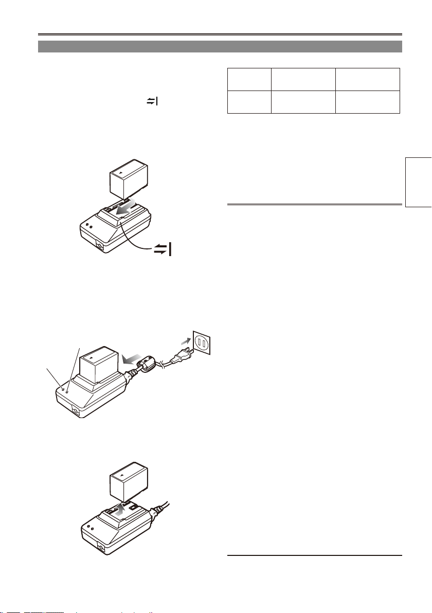
The battery
Charging
Before using the battery, fully charge it with the AC
adapter.
Keep a spare battery with you.
1 Align the battery with the marking on
the AC adapter, place it at, and slide it in
the direction shown below.
You cannot charge the battery if the DC cord
•
is connected to the DC OUT connector, so
disconnect it rst.
2 Plug the AC cord into the power outlet.
The POWER lamp and CHARGE lamp on
•
the AC adapter light, and charging begins.
If the CHARGE lamp does not light when
•
attached, detach the battery and then attach
it again.
CHARGE
POWER
When the battery is charged, the CHARGE
•
lamp on the AC adapter goes out.
3 Slide the battery and remove it.
Recording time of included battery
Capacity
5400 mAh
The times given above are approximate for when
•
scenes are shot in the DVCPRO HD mode while
not using the LCD monitor.
The times apply when the ambient operating
•
temperature is 68°F (20°C) and humidity is 60%.
Charging may take longer at other temperatures
and humidity levels.
Keep metal objects (such as necklaces
•
and hairpins) away from the battery.
Shortcircuiting may occur across the
terminals, causing the battery to heat up,
and you may seriously burn yourself if you
touch the battery in this state.
The battery becomes hot while it is being
•
used or charged. The camera-recorder itself
also becomes hot during use.
The recordable time reduces if you repeatedly
•
start and stop recording.
Discharge the battery before storing it. When
•
storing it for an extended time, charge it at
least once a year, use up its charge in the
camerarecorder, and then store it again.
If the battery is extremely hot or cold, the
•
CHARGE lamp will blink several times before
charging starts.
If the CHARGE lamp continues to blink even
•
when the battery temperature is normal, there
may be something wrong with the battery or
AC adapter. Contact your dealer.
The battery takes longer to charge when it is
•
warm.
The AC adapter can interfere with radio
•
reception so keep radios at least 1 meter
away from it.
The AC adapter may make some noise when
•
you are using it, but this is normal.
You cannot charge the battery when
•
supplying power to the camera-recorder from
the AC adapter.
Operation of battery pack CGR-D16 (1600
•
mAh) (sold separately) is not guaranteed.
Recharging
time
Approx. 330
min.
Continuous
recording time
Approx. 160
min.
Preparation
15

16
Installing and removing the power supply
Installing and removing the battery
Installation
1 Insert the battery until it clicks into place.
Removal
1 Set the POWER switch to OFF, and check
2 While pressing the battery release button,
Connecting and disconnecting the power cord
Installation
2 Slide the DC cord’s battery connector to
1 Connect the DC cord to the AC adapter.
2 Plug the AC power supply cord into the
power outlet.
3 Slide the DC cord’s battery connector to
the direction of the arrow until it clicks into
place.
that the mode lamp is off.
raise up the battery to remove it.
Support the battery with your hand to ensure
•
that it will not fall.
Mode lamp
Battery release button
the direction of the arrow while pressing
the battery release button.
Battery release button
DC cord’s battery
connector
Removal
1 Set the POWER switch to OFF, and check
that the mode lamp is off.
3 Disconnect the AC power supply cord from
the power outlet.
CAUTION:
This apparatus can be operated at a voltage in
the range of 110 – 240 V AC.
Voltages other than 120 V are not intended for
U.S.A. and Canada.
Operation at a voltage other than 120 V AC may
require the use of a different AC plug. Please
contact either a local or foreign Panasonic
authorized service center for assistance in
selecting an alternate AC plug.
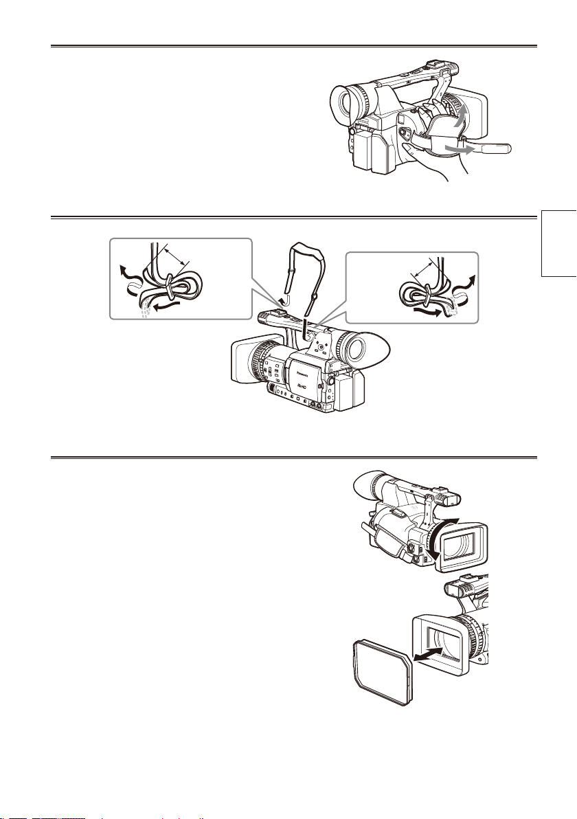
Adjusting the hand strap
Adjust the hand strap to suit your hand.
1 Open the cover and adjust the length.
2 Close the cover.
Make sure the cover is fully closed.•
Attaching the shoulder strap
Attach the shoulder strap and use it as a precaution against dropping the camera.
20 mm or more
20 mm or more
Detaching and attaching the lens hood
Detaching the lens hood
Turn the lens hood counterclockwise to detach it.
•
Attaching the lens hood
Turn the lens hood clockwise until it clicks to
•
secure it in position.
Be sure to attach the lens hood cap to protect the
•
lens when not in use.
Preparation
17
18
The remote control
OSD
COUNTER
RESET TITLE
STILL ADV
PAUSE
STILL ADV
INDEX
SELECT
STORE
OFF/ON
P.B.DIGITAL
VAR.
SEARCH
VOL+
-
PB.
ZOOM
MENU
SET
ITEM
STOP INDEX
MULTI/
P-IN-P
REC A.DUB
PLAY/REW FF/
ZOOM
DATE/
TIME
PHOTO
SHOT
START/
STOP
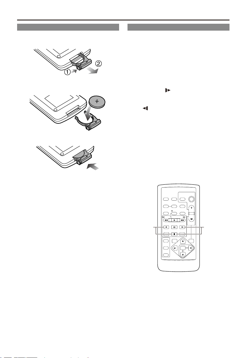
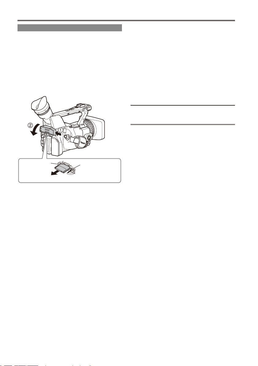
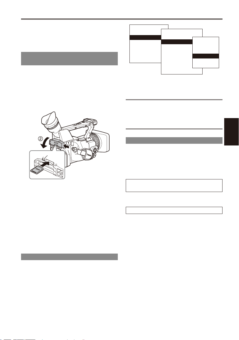
Insert the battery
1 Push the catch in the direction shown by
arrow A to remove the holder.
2 Insert the battery with the “+” marked side
facing up.
3 Return the holder to its original position.
When the battery (CR2025) has run out, replace
•
it with a new one. (The battery lasts about one
year, depending on the frequency of use.)
If the remote control unit fails to work even when
it is operated near the camera-recorder’s remote
control sensor, the battery has run out.
Keep the battery out of the reach of children.
•
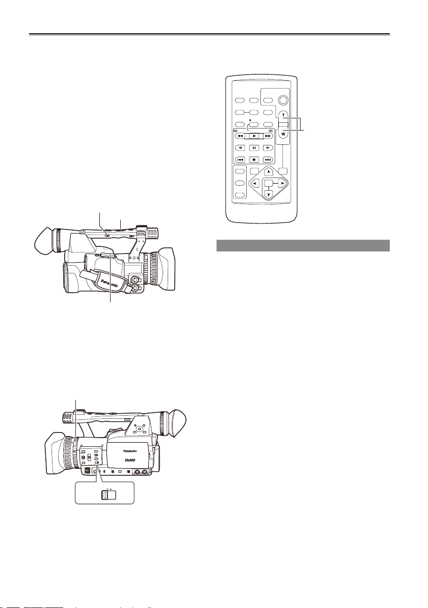
Remote control setup
When using two camera-recorders simultaneously,
set this camera-recorder and the remote control
to either “operation mode 1” or “operation mode 2”
so the remote control does not operate the wrong
camera-recorder by mistake.
Setting
Wireless remote control
•
Press the MCR operation buttons STOP ( g )
and STILL ADV ( ) at the same time to set the
remote control unit for use in “operation mode 1”.
Alternatively, press the STOP ( g ) and STILL
ADV ( ) buttons at the same time to set the
remote control unit for use in “operation mode 2”.
When the battery in the remote control unit is
replaced, the remote control unit is set for use in
“operation mode 1”.
Camera
•
In the setup menus, OTHER FUNCTIONS
screen, REMOTE, set to 1 or 2. (Page 110)
If different settings are used for the camerarecorder and remote control unit, “REMOTE” lights
in red on the viewnder and LCD monitor.
Operation
mode 2
Operation
mode 1
Turn on/off the camera
SLOT SEL
MODE
CAM
MCR
PC
POWER
ON
OFF
While pressing the lock release, turn the POWER
switch.
Turn on the camera:
The mode lamp (CAM) lights red (CAM mode) and
the camera is now in the shooting standby mode.
Turn off the camera:
The mode lamp (CAM) goes out.
Power saving mode
•
When the camera is left idle in pause mode
for about 5 minutes, it will behave as follows
depending on what POWER SAVE settings
have been made in the setting menu OTHER
FUNCTIONS screen (Page 112).
ON: The camera-recorder turns off automatically.
OFF: The camera-recorder does not turn off
automatically.
See the setup menus, OTHER FUNCTIONS
screen, POWER SAVE (Page 112) for details.
When the operation mode buttons ash in
•
sequence starting with the top one and the power
then goes off, it means that there is no charge left
in the battery. Recharge the battery.
Tally lamp
Mode lamp
Mode button
Preparation
Lock release
The tally lamp can be made to light up during
shooting by selecting “ON” as the REC LAMP
setting in the OTHER FUNCTIONS screen.
(Page 111)
When the camera-recorder is in any of the
following states, the tally lamp blinks.
When an operation initiated by the remote control
•
unit has been received (8 blinks/sec.)
When the remaining battery capacity runs out (4
•
blinks/sec.)
When the available recording space on the P2
•
card or the battery power is low (1 blink/sec.)
When removing the P2 card during access (4
•
blinks/sec.)
When there is no recording space left on the P2
•
card (4 blinks/sec.)
Tally lamp
19
Viewnder
POWER
ON
OFF
This camera has two viewnders; one is a
miniature LCD in the viewnder and the other is a
retractable 3.5-inch LCD.
Use the viewnder that best suits the application
and shooting conditions.
The brightness and hue may differ between the
•
images appearing on the viewnder and LCD
monitor and those displayed on a TV monitor.
To see how the nal images will appear, check
them on a TV monitor.
Images are always displayed on the viewnder.
•
Using the viewnder
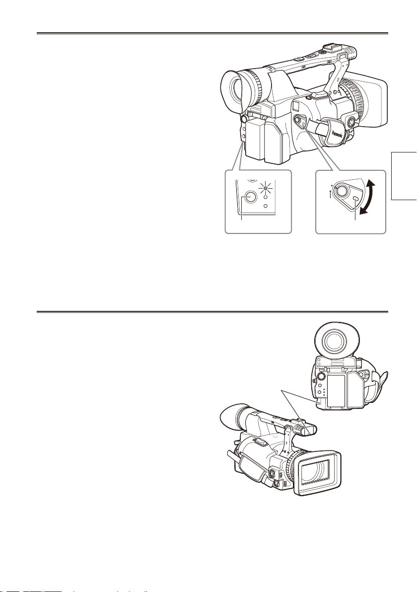
1 Set the POWER switch to ON and check
that images appear in the viewnder.
Keep the LCD monitor closed.
•
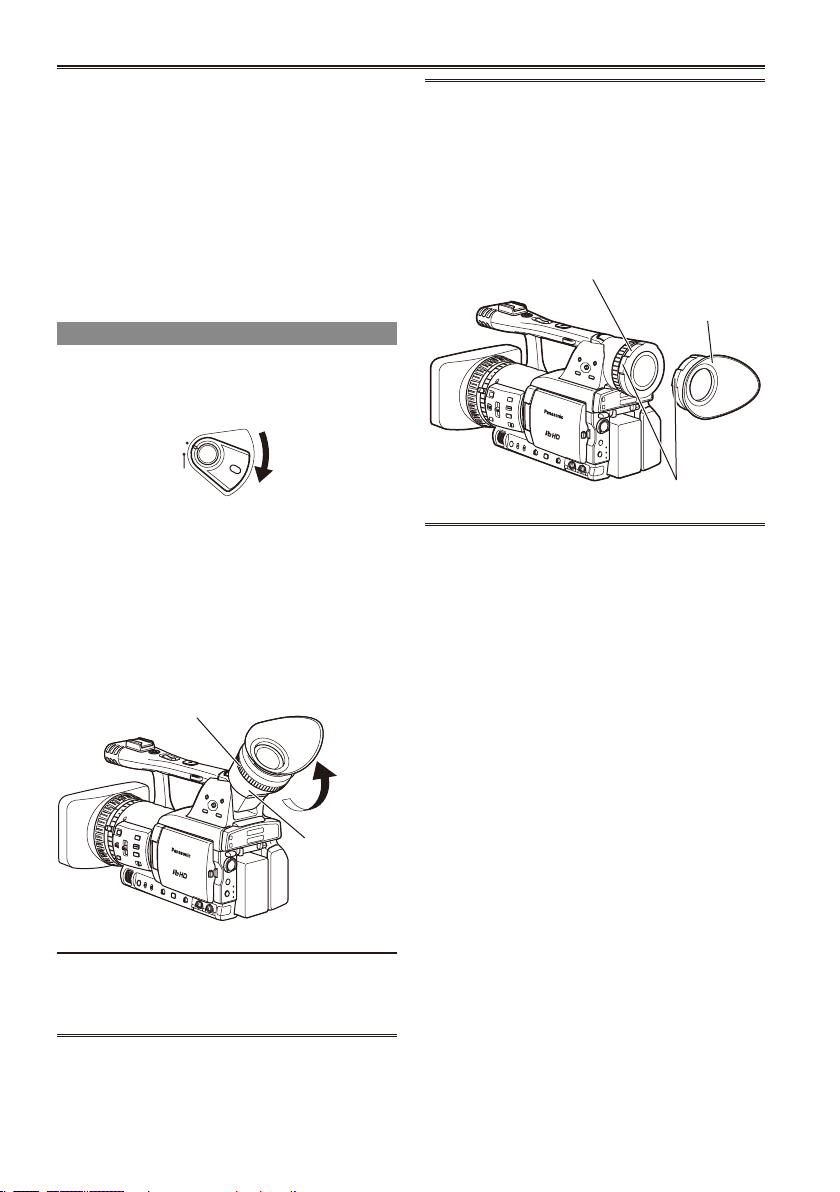
2 Adjust the viewnder’s angle so that the
screen is positioned where it is easiest to
see.
You can move the view nder out to about 90
•
degrees perpendicular to the camera.
3 Adjust the diopter adjustment lever so
that you can see the characters on the
viewnder screen clearly.
Viewnder diopter dial
Fitting the eye cup
Attach the eye cup by aligning the projections
on the eye cup holder and eye cup and tting
them together.
Turning the eye cup after attaching it may
•
cause the eye cup holder to come off. If the
eyecup holder does come off, see “Cleaning
the Viewnder” (page 119) for details on how
to ret it.
Eye cup holder
Eye cup
Projection
Do not point the eye piece at the sun or
other strong light source.
Light concentrated by the lens could damage
•
internal components and poses a re hazard.
20
Eye piece
BARS
CH1 SELECT
RESET/TC SET
REC
CH2 SELECT
AUDIO
INT(L)
INPUT1
INPUT2
SHUTTER
SPEES SELECT
INT(R)
INPUT2
INPUT1
MIC POWER+48V
ON
OFF
INPUT2
ON
OFF
LCD
ZEBRA
EVF DTL
OIS
WFM
COUNTER
Using the LCD
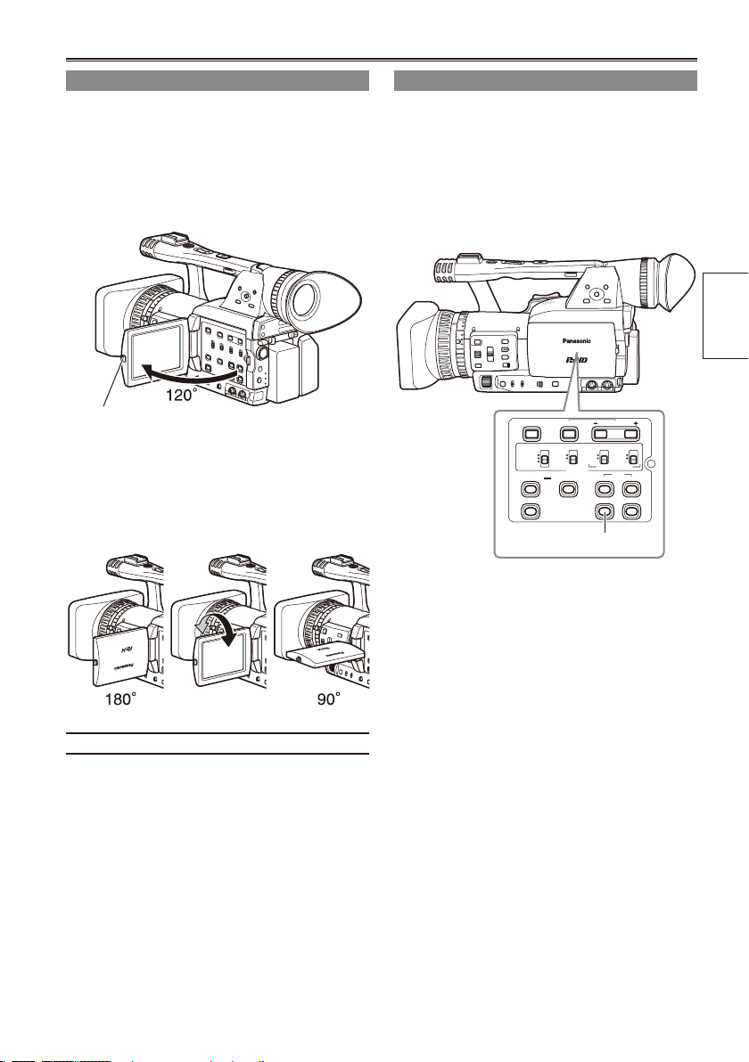
1 Set the POWER switch to ON.
2 Hold down the OPEN button to open the
LCD monitor.
It can open out to 120 degrees. Do not try
•
to open it further as this will damage the
camera.
OPEN button
3 Position the LCD monitor where it is
easiest to see.
The monitor can be rotated 180 degrees
•
toward the lens and 90 degrees toward you.
Do not apply unnecessary force to the
•
open LCD. This can damage the camera.
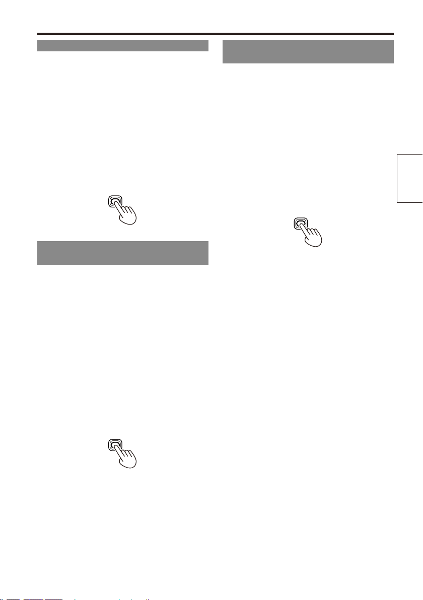
Emphasizing outlines
Emphasizing the outlines of the images you see
in the viewnder or on the LCD makes it easier to
focus.
Emphasizing the outlines does not effect the
images you shoot.
1 In CAM mode, press EVF DTL.
“EVF DTL ON” appears on the screen for
about 2 seconds.
Preparation
EVF DTL button
Press EVF DTL again to return to the original
display. “EVF DTL OFF” appears on the screen
for about 2 seconds.
Ensure the LCD is fully closed.
•
21

22
Viewnder (continued)
DISPLAY SETUP
PUSH MENU TO RETURN
ZOOM·FOCUS NUMBER
ON
TOTAL
PARTIAL
NORMAL
–– ––
–– ––
MIRROR
CARD/BATT
LCD SET
EVF SET
P2CARD REMAIN
OTHER DISPLAY
LCD BACKLIGHT
SELF SHOOT
PUSH MENU TO RETURN
EVF COLOR LEVEL
EVF BRIGHTNESS
[– ] – –– –– ––– +–– –– ––– – [ +]
EVF CONTRAST
[– ] – –– –– ––– +–– –– ––– – [ +]
[– ] – –– –– ––– +–– –– ––– – [ +]
EVF SET
PUSH MENU TO RETURN
EVF COLOR LEVEL
EVF BRIGHTNESS
[– ] – –– –– ––– +–– –– ––– – [ +]
EVF CONTRAST
[– ] – –– –– ––– +–– –– ––– – [ +]
[– ] – –– –– ––– +–– –– ––– – [ +]
EVF SET
Adjusting the screen display
1 Set the POWER switch to ON. (Page 19)
2 Press the MENU button.
For menu operation (Page 94)
•
You can also use the menu buttons on the
•
remote control. (Page 14)
3 Viewnder adjustments
Select YES under EVF SET on the setting
menu DISPLAY SETUP screen.
LCD monitor adjustments
Set YES under LCD SET on the setting menu
DISPLAY SETUP screen.
4 Push the Operation lever in the
direction to select the item.
or r
e
5 Push the Operation lever in the
w
or q
direction to make adjustment.
6 Press MENU three times to exit the menus.
You can return the settings for EVF SET and
•
LCD SET to the factory settings by selecting
the item and pressing COUNTER RESET (if it
is possible to change the item at that time).
The viewnder display can be in color or black
•
and white. (See the setup menus, DISPLAY
SETUP screen, EVF COLOR.) The resolution
is the same for both of them.
Adjusting the backlight
LCD
LCD
LCD
The steps below show how to set the brightness of
the LCD monitor to one of three possible levels.
1 Select LCD BL under LCD on the setting
menu SW MODE screen.
This assigns LCD BL to the LCD button.
2 Press the LCD button.
Each press of the button switches backlight
brightness in the following order: NORMAL
(standard) " LOW (dark) " HIGH (bright) "
NORMAL.
These settings persist even when the
•
camera-recorder is turned off.
Flipping images vertically and
horizontally
Use this function to ip an image vertically
or horizontally to check the aspect ratio or
composition on the LCD monitor.
This feature affects only the image in the viewnder
or on the LCD monitor, not the recorded image.
1 Select LCD REV under LCD on the setting
menu SW MODE screen.
This assigns LCD REV to the LCD button.
Switching between overscan and underscan
Use this function to underscan or overscan the
image shown in the viewnder or on the LCD
monitor.
1 Select OVERSCAN under LCD on the
setting menu SW MODE screen.
This assigns OVER SCAN to the LCD button.
2 Press the LCD button.
This button toggles between overscan and
•
underscan at each press.
The unit returns to underscan mode the next
•
time it is powered up.
In overscan mode, a frame appears on the
•
screen.
Preparation
2 Press the LCD button.
This button toggles between the normal and
•
ipped image at each press.
No screens are displayed when the image
•
is ipped.
The unit returns to normal image mode the
•
next time it is powered up.
23
Setting the calendar
OTHER FUNCTIONS
PUSH MENU TO RETURN
CLOCK SET –– ––
+0: 00
OFF
–– ––
00012H
00012H
–– ––
MIRROR
TIME ZONE
OPERATION
EVF SET
POWER SAVE
MENU INIT
OPERATION
SELF SHOOT
OTHER FUNCTIONS
PUSH MENU TO RETURN
CLOCK SET ––– –
YES
OFF
–– ––
00012H
00012H
–– ––
MIRROR
TIME ZONE
OPERATION
EVF SET
POWER SAVE
MENU INIT
OPERATION
SELF SHOOT
CLOCK SET
PUSH MENU TO RETURN
YEAR 2008
OCT
01
12
00
MONTH
+/– : PUSH y / t
DAY
HOUR
MIN
SEL : PUSH q / g
CLOCK SET
PUSH MENU TO RETURN
YEAR 2008
OCT
01
12
00
MONTH
+/– : PUSH y / t
DAY
HOUR
MIN
SEL : PUSH q / g
CLOCK SET
PUSH MENU TO RETURN
YEAR 2008
DEC
01
12
00
MONTH
+/– : PUSH y / t
DAY
HOUR
MIN
SEL : PUSH q / g
CLOCK SET
PUSH MENU TO RETURN
YEAR 2008
DEC
25
17
20
MONTH
+/– : PUSH y / t
DAY
HOUR
MIN
SEL : PUSH q / g
The CLOCK SET value is recorded in the contents
(clip), and affects the sequence of playback of the
thumbnails. Before carrying out recording, be sure
to check and set CLOCK SET and TIME ZONE.
This shows you how to adjust the calendar to 5:20
PM on December 25, 2008.
1 Set the POWER switch to ON. (Page 19)
2 Press the MENU button.
3 Push the Operation lever in the
direction to set the time difference from
Greenwich Mean Time under TIME ZONE
on the setting menu OTHER FUNCTIONS
screen. (Page 111)
(Example of MENU in the CAM mode)
For menu operation (Page 94)
•
You can also use the menu buttons on the
•
remote control. (Page 14)
or r
e
6 Push the Operation lever in the
direction
r
to move to the MONTH setting.
7 Push the Operation lever in the
or q
w
direction to set MONTH to DEC.
8 Set DAY, HOUR, and MIN using the method
shown in steps 4 and 5.
This is a 24-hour clock.
•
4 In the setup menus, OTHER FUNCTIONS
screen, CLOCK SET, select YES.
5 Push the Operation lever in the
direction to set YEAR to 2008.
24
Choose a year between 2000 and 2030.
or q
w
9 Press MENU three times to exit the menus.
The clock can vary in accuracy so check that
•
the time is correct before shooting.
When using the camera overseas, do not
•
set the CLOCK SET option to the local time,
but instead enter the time difference from
Greenwich mean time according to TIME
ZONE.
Basic shooting operations
3
4
1
POWER
ON
OFF
1
2
3
POWER
ON
OFF
POWER
ON
OFF
AUTO
MANUAL
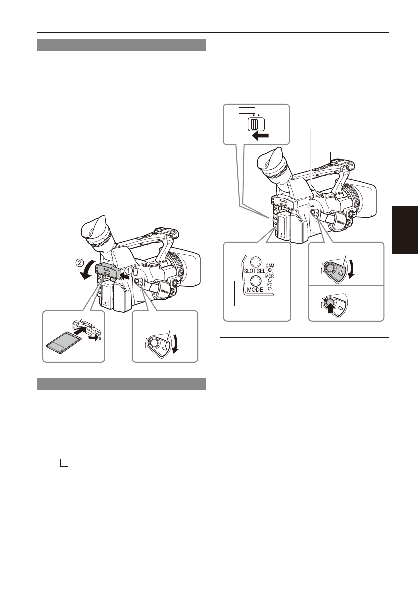
Preparing to shoot
1 Set the POWER switch to ON. (Page 19)
2 Lift up the viewnder, press the side of the
card slot cover (A), and slide the cover (B)
to open it.
3 Insert the P2 card securely in the card slot.
4 Push the P2 card eject button to the
direction of the arrow, and close the card
slot cover.
There are two card slots.
•
Be absolutely sure to close the card slot
•
covers to keep the dust out.
Do not remove the P2 card while the P2 card
•
access lamps are blinking orange. (Page 26)
Lock
release
3 Press the START/STOP button (Red) on the
POWER switch to start shooting.
Press again to return to the camera to the
•
shooting standby mode.
Use the handle START/STOP button to make
•
it easier to shoot from low angles.
LCD
side
Mode lamp
Mode button
REC CHECK
button
Handle START/STOP
button
Lock release
Shooting
Under the following circumstances, even if you
press the STOP button it may take some time
until the writing to the P2 card nishes. For this
Shooting in auto mode
1 Turn the POWER switch to ON. (Page 19)
Check that the mode lamp (CAM) is lighted
•
red.
reason, the operation will not be acknowledged
if you press the START button too soon.
Stopped after only a short recording time
•
Stopped immediately after the recording has
•
moved to a second P2 card
2 Switch the AUTO/MANUAL switch to AUTO
to select auto mode.
“ A ” appears on the viewnder and LCD
•
screens.
The focus, gain, iris and white balance are
•
adjusted automatically.
25
Basic shooting operations (continued)
PROTECT
Checking photos taken (REC CHECK)
In the shooting pause mode, press the REC
CHECK button.
This plays back about 2 seconds of the video and
audio of the most recently recorded clip before
returning to pause mode.
Note that this REC CHECK portion will also be
•
recorded to any equipment you have set up to
make backup recordings.
The REC CHECK function does not work in PC
•
and MCR mode.
The HD recording(720P/60P) settings are
already made in the default mode. (To view the
current settings, see page 41.)
P2 card access lamps
CAM mode (MCR)
Lights green:
Data can be saved onto the cards or loaded
from them.
Blinks green (slow):
No available space on card, card is write-
protected
Lights orange:
Slot that is the object of recording
Blinks orange:
Data is now being accessed.
Blinks orange (fast):
A card is now being recognized.
Both lamps blink orange:
Ejection of card during access
Off:
Cards have not been inserted or formatted.
Insertion of incompatible card.
PC mode (USB DEVICE)
Blinks orange: Data is now being accessed.
Off: A status other than access underway.
PC mode (1394 HOST)
Lights green:
Access standby.
Blinks orange:
Data is now being accessed.
Off:
Cards have not been inserted or formatted.
Insertion of incompatible card.
P2 card access lamp
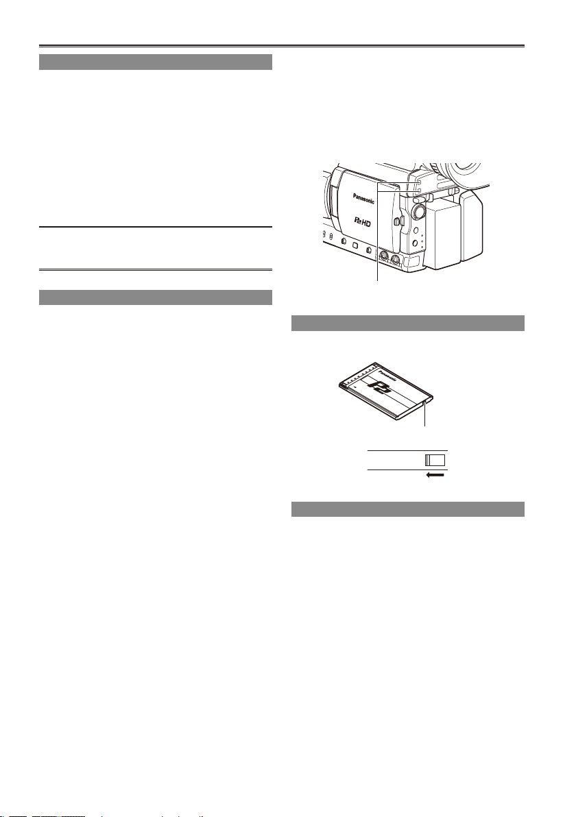
Protecting against a possible erasure
Switch the write-protect switch of the P2 card to
[PROTECT].
Write-protect switch
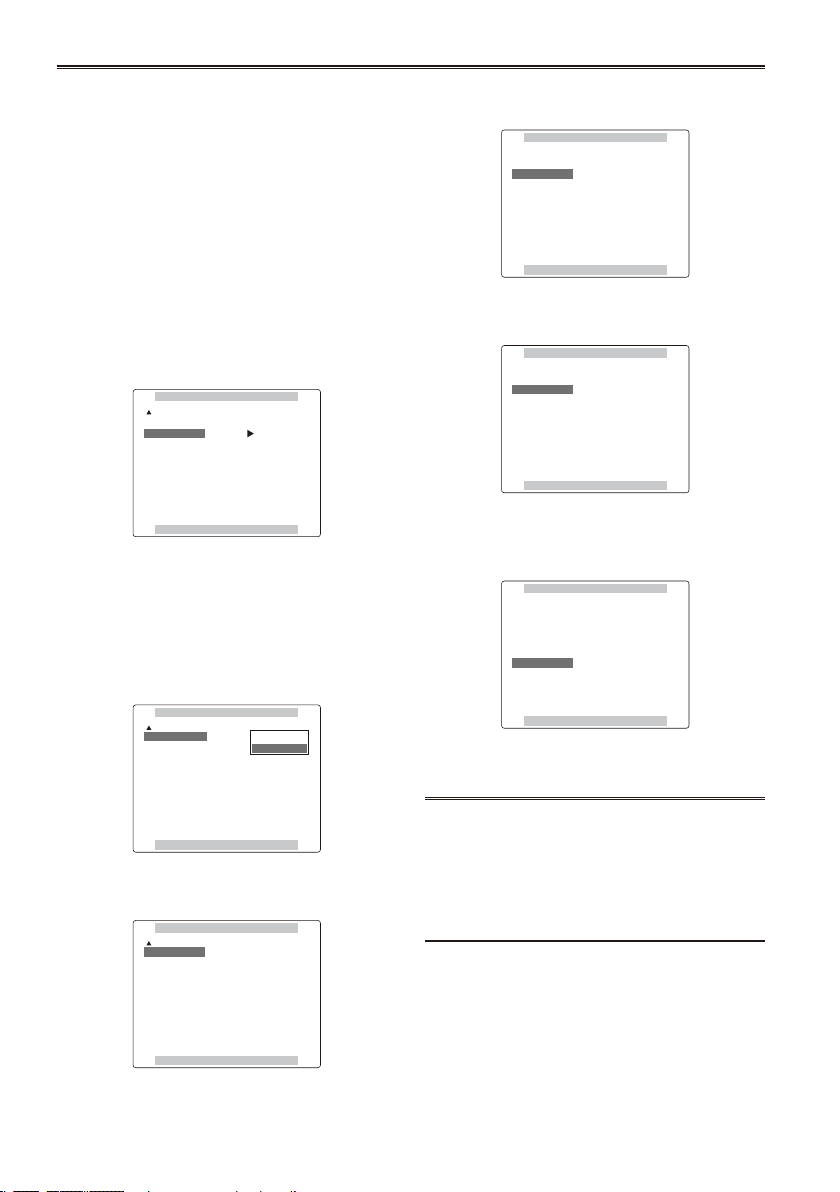
Formatting P2 cards
1 Set the POWER switch to ON. (Page 19)
2 Press the mode button and set it to MCR
mode (the MCR lamp lights).
Thumbnails are displayed.•
PC mode (1394 DEVICE)
Blinks orange: Connected
Off: Not connected
26
3 Press the MENU button.
MENU
PUSH-SET
SLOT SEL
MODE
CAM
MCR
PC
THUMBNAIL
OPERATION
PROPERTY
META DATA
EXIT
DELETE
FORMAT
REPAIR CLIP
RE-CONNECTION
EXCH.THUMBNAIL
EXIT
SLOT1
SLOT2
SD CARD
EXIT
For menu operation (Page 94)
•
Operation lever
4 On the menu, select OPERATION and then
FORMAT. (Page 68)
A screen such as the one shown below
•
appears. Select the number of the slot
into which you inserted the P2 card to
be formatted. Select EXIT to cancel the
formatting.
When you press the MENU button, the menu
•
display disappears.
MENU button
Mode button
Mode lamp
5 Select YES on the conrmation screen.
The selected P2 card is formatted.
•
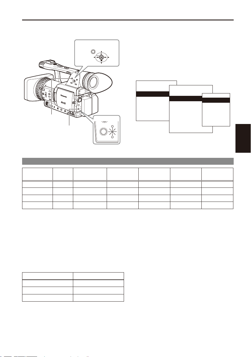
Recording times
Card model Capacity
AJ-P2C004HG 4 GB approx. 16 min. approx. 8 min. approx. 4 min. approx. 10 min. approx. 8 min.
AJ-P2C008HG 8 GB approx. 32 min. approx. 16 min. approx. 8 min. approx. 20 min. approx. 16 min.
AJ-P2C016RG 16 GB approx. 64 min. approx. 32 min. approx. 16 min. approx. 40 min. approx. 32 min.
AJ-P2C032RG 32 GB approx. 128 min. approx. 64 min. approx. 32 min. approx. 80 min. approx. 64 min.
The AJ-P2C002SG (2 GB) card cannot be used.
•
The displayed available space includes the management area, and so the space available for recording is
•
DVCPRO/DV 2-
channel audio
smaller than this.
Concerning the division of clips recorded on P2 cards
•
When using a P2 card of at least 8 GB in this camera, if the continuous recording time for a single
session exceeds the time shown in the following table, recording will be automatically resumed as a
different clip. When performing a thumbnail operation (display, delete, restore, copy, etc.) on clips using
P2 cards, you can operate them as a single clip. When you are using non-linear editing software and a
PC, for example, the clips are displayed individually.
Recording Format Recording times *1 The 720P/30PN and 720P/24PN formats are not
DVCPRO HD*1 approx. 5 min.
DVCPRO50 approx. 10 min.
DVCPRO/DV approx. 20 min.
DVCPRO50 4-
channel audio
included in the DVCPRO HD recording format.
DVCPRO HD*1
DVCPRO HD
720P/24PN
DVCPRO HD
720P/30PN
Shooting
•
•
When using any other types of cards, the driver installed in the camera-recorder may need to be updated.
(Page 118)
For the latest information not available in the Operating Instructions, visit the P2 Support Desk at the
following Web sites.
https://eww.pavc.panasonic.co.jp/pro-av/
27
28
Basic shooting operations (continued)
4
3
Remove the P2 card
1 Lift up the viewnder, press the side of the
card slot cover (A), and slide the cover (B)
to open it.
2 Check that the P2 card access lamp is not
blinking orange.
3 Raise the P2 card eject button and press it.
4 Remove the P2 card.
During playback, a P2 card inserted into the
•
empty slot will not be recognized and the P2
card access lamp will not light. When playback is
completed, the P2 card recognition will begin.
You can use ACCESS LED on the OTHER
•
FUNCTIONS screen to set the P2 card access
lamps so that they will always be off. In this case,
either turn off the power or wait until enough time
has passed after inserting the cards or stopping
operation before ejecting the cards.
If a P2 card is ejected while thumbnails are
•
displayed, the thumbnail screen is released.
Cautions in using P2 cards
Before using a P2 card, be sure to format it with
a P2 device.
P2 card
access lamp
Do not eject the P2 card or turn the power off
•
under the following circumstances, since doing
so may cause a malfunction in the card:
1) While the orange P2 card access lamp is
blinking after the card is inserted (and until it
stops blinking).
2) During recording, during the recording nish
process, or while the access lamp is blinking.
If a P2 card is ejected during formatting or while
•
its data is being accessed, “TURN POWER
OFF” appears in the viewnder, and a warning is
indicated by the tally lamp. If this happens, turn
the power off and back on again.
When a card is ejected during formatting:
•
Format the card again.
When a card is ejected while its data is being
•
accessed:
The clips may be thrown out of order.
(Page 57) Check the clips and repair them.
(For details on repairing clips, see page 68.)
Immediately after pre-recording, a P2
•
card inserted into an empty slot will not be
immediately recognized.
P2 card eject
button
Using SD/SDHC memory cards
2
THUMBNAIL
OPERATION
PROPERTY
META DATA
EXIT
DELETE
FORMAT
REPAIR CLIP
RE-CONNECTION
EXCH.THUMBNAIL
EXIT
SLOT1
SLOT2
SD CARD
EXIT
You can use SD and SDHC memory cards (the
term “SD memory card” is used for both hereafter)
to save and load SCENE les and USER les, and
to upload clip meta data. (Page 55)
Installing and removing the SD memory card
Installation
1 Lift up the viewnder, press the side of the
card slot cover (A), and slide the cover (B)
to open it.
2 Insert the card while making sure it is
oriented in the proper direction.
Access lamp
3 Close the card slot cover.
Removal
1 Open the card slot cover, and check that
the access lamp is not lit.
2 Press the card further into the unit, grasp
the card, and then remove.
3 Close the card slot cover.
Formatting SD memory card
1 Set the POWER switch to ON. (Page 19)
2 Press the mode button and set it to MCR
mode (the MCR lamp lights).
3 Press the MENU button.
4 On the menu, select OPERATION, FORMAT
and then SD CARD. (Page 68)
Select EXIT to cancel the formatting.•
5 Select YES on the conrmation screen.
The selected SD memory card is formatted.
•
You can also format from the SD CARD
•
FORMAT option on the CARD FUNCTIONS
screen. (Page 110)
With SDHC cards, 32 KB of capacity will have
•
been used.
Cautions in using SD memory cards
SD memory cards used with the AG-HPX170P
•
should conform to SD or SDHC standards. Be
sure to format cards using the AG-HPX170P.
SD memory cards with the following capacity can
be used for the AG-HPX170P.
SD (from 8 MB to 2 GB):
8 MB 16 MB 32 MB 64 MB 128 MB
256 MB 512 MB 1 GB 2 GB
SDHC (4 GB to 16 GB):
4 GB 8 GB 16 GB
For the latest information not available in the
Operating Instructions, visit the P2 Support Desk
at the following Web sites.
https://eww.pavc.panasonic.co.jp/pro-av/
SD memory cards must not be used or stored in
•
an environment where they may be Exposed to
high temperatures/humidities;
Exposed to water droplets; or
Electrically charged.
Be sure always close the cover when using an
•
SD memory card.
See also “Checkpoints for using memory cards”
•
on page 122.
Shooting
29
Using the zoom function
OSD
COUNTER
RESET TITLE
STILL ADV
PAUSE
STILL ADV
INDEX
SELECT
STORE
OFF/ON
P.B.DIGITAL
VAR.
SEARCH
VOL+
-
PB.
ZOOM
MENU
SET
ITEM
STOP INDEX
MULTI/
P-IN-P
REC A.DUB
PLAY/REW FF/
ZOOM
DATE/
TIME
PHOTO
SHOT
START/
STOP
MANUAL
ZOOM
SERVO
This camera has a 13 x optical zoom function.
Zoom with the zoom button or the zoom ring.
Zoom button
Set the ZOOM switch to SERVO so that you can
use the motor-driven zoom.
T : Zoom in
W : Zoom out
Gently press the zoom button on the grip to zoom
slowly, rmly press to zoom faster.
You can change the zoom speed on the handle
zoom button by selecting one of three speeds with
the HANDLE ZOOM switch.
Set the HANDLE ZOOM switch speeds by going
to the setup menus, SW MODE screen HANDLE
ZOOM (Page 101).
HANDLE ZOOM switch
Handle zoom button
Zoom button
Zoom ring
Set the ZOOM switch to MANUAL so that you can
use the zoom ring.
You cannot use the zoom ring if the ZOOM switch
•
is set to SERVO. Trying to use it could damage
the camera.
Zoom ring
On the remote control
Press ZOOM/VOL to zoom with the motor drive.
Zoom speed is xed at medium.
•
ZOOM/VOL button
Digital zoom function
Assign the D.ZOOM function to any of the USER
1 – 3 buttons to enable use of the digital zoom.
(Page 42)
Each press of the USER button to which D.ZOOM
is assigned switches the zoom ratio in the following
order: OFF (x1) " x2 " x5 " x10 " OFF (x1).
The viewnder and the LCD monitor indicate the
•
zoom ratio when a setting other than OFF (x1) is
selected.
Digital zoom is available only in the 1080i/60i
•
format.
Digital zoom is not available when OFF is
•
selected under DRS (Page 99) on the setting
menu SCENE FILE screen.
While using the zoom function, the slow shutter
•
is disabled. While using the slow shutter, you
cannot use the digital zoom function.
Digital zoom cannot be changed during
•
recording.
30
 Loading...