

Page 1
Electrical Adjustments
0. General
When carry-out the electrical settings in many cases a video
signal must be applied to the monitor. A computer with :
- ATI GPT-1600 (4822 397 10065), Mach 64 (up to 107kHz)
are used as the video signal source. The signal patterns are
selected from the "service test software" package, see user
guide 4822 727 21046 (GPT-1600).
0.1 This monitor has 35 factory-preset modes as below
.
31.469 KHz/70.087 Hz, 640 X 350
31.469 KHz/59.941 Hz, 640 X 480
31.468 KHz/70.084 Hz, 720 X 400
37.5 KHz/75 Hz, 640 X 480
37.861 KHz/72.810 Hz, 640 X 480
37.861 KHz/85.081 Hz, 640 X 350
37.879 KHz/60.317 Hz, 800 X 600
37.927 KHz/85.039 Hz, 720 X 400
43.269 KHz/85.008 Hz, 640 X 480
46.875 KHz/75.000 Hz, 800 X 600
48.077 KHz/72.188 Hz, 800 X 600
48.363 KHz/60.004Hz, 1024X 768
49.722 KHz/74.546Hz, 832 X 624
50.628 KHz/100.10 Hz, 640 X 480
53.674 KHz/85.061 Hz, 800 X 600
56.476 KHz/70.069 Hz,1024X 768
60.000 KHz/60.000 Hz,1280 X 960
60.023KHz/75.029Hz, 1024 X 768
63.923 KHz/100.00 Hz, 800 X 600
63.981KHz/60.020Hz, 1280 X 1024
67.500 KHz/75.00Hz, 1152 X 864
68.677KHz/84.997Hz, 1024 X 768
68.681KHz/74.979Hz, 1152 X 870
71.809KHz/76.15 Hz, 1152 X 900
75.000KHz/60.000 Hz, 1600 X 1200
79.976KHz/75.024 Hz, 1280 X 1024
0.2 With normal VGA card:
If not using the ATI card during repair or alignment, The
service engineer also can use this service test software
adapting with normal standard VGA adaptor and using
standard VGA mode 640 x 480, 31.5 kHz/60 Hz (only) as
signal source.
0.3 AC/DC Measurement:
The measurements for AC waveform and DC figure is based
on 640 x 480 31.5 kHz/60 Hz resolution mode with test
pattern "gray scale".
Power input: 110V AC
1. B+ supply voltage (3157) 210Vdc
- Apply a video signal in the 1024 x 768 with 68.7 kHz/85Hz
mode.
- Select the "cross-hatch" pattern.
- Set the brightness control and the contrast control to the
minimum position.
- Pre-set trimming potentiometer 3157(B+) and 3698(EHT)
in mid-position.
- Set Vg2 (screen) to fully Counter-clockwise (zero
beamcurrent).
- Connect a dc voltmeter between the joint of capacitor 2131
and ground (common ground).
- Set the B+ trimming potentiometer 3157 so that the reading
on the dc voltmeter is 210 V +/- 0.5 Vdc.
2. High-voltage EHT (3698)
- Apply a video signal in the 1024 x 768 with 68.7 kHz/85Hz
mode.
- Select the "cross-hatch" pattern.
- Set the brightness control and the contrast control to the
minimum position.
- Turn off the power.
81.250 KHz/65.000 Hz, 1600 X 1200
83.640 KHz/59.999 Hz, 1792 X 1344
85.938 KHz/85.002 Hz, 1280 X 960
86.333 KHz/59.995 Hz, 1856X 1392
87.500 KHz/70.000 Hz, 1600 X 1200
90.000 KHz/60.000 Hz, 1920 X 1440
91.146 KHz/85.024 Hz, 1280 X 1024
93.750 KHz/75.000Hz, 1600 X 1200
106.250KHz/85.00 Hz, 1600 X 1200
106.270KHz/74.997Hz, 1792 X 1344
109P2 GS3 CM25
Go to cover page
9
13
- Connect a "high-voltage voltmeter" between the highvoltage connection of the picture tube and earth.
- Turn on the power.
- Set the EHT trimming potentiometer 3698 so that the "highvoltage voltmeter" reads 25.0 kV +/- 0.2 kV .
- Turn off the power.
- Remove the "high-voltage voltmeter" from the picture tube.
- Turn on the power again.
3. Monitor the following auxiliary voltages.
SOURCE ACROSS C2362 + 8.0V +/- 0.5VDC.
SOURCE ACROSS C2143 + 5.0V +/- 0.5VDC.
SOURCE ACROSS C2362 +12.0V+/- 0.5VDC.
SOURCE ACROSS C2134 +15.0V +/- 1.0VDC.
SOURCE ACROSS C2137 - 15.5V +/- 1.0VDC.
SOURCE ACROSS D6148"+" 6.3 V+/- 0.5VDC.
SOURCE ACROSS C2131 + 210.0V +/-1.5VDC.
SOURCE ACROSS C2133 + 82.7 V +/-2.0VDC.
4. General conditions for alignment
4.1 During all alignments, supply a distortion free AC mains
voltage to set via an isolating transformer with low internal
impedance.
4.2 Align in pre-warmed condition, at least 30 minutes warmup with nominal picture brightness.
4.3 Purity, geometry and subsequent alignments should be
carried out in magnetic cage with correct magnetic field.
Northern hemisphere : H=0, V=430+/-50 mG, Z=0
Southern hemisphere : H=0, V=-520+/-50 mG, Z=0
Equatorial Support : H=0, V=0 mG, Z=0
4.4 All voltages are to be measured or applied with respect to
ground.
Note: Do not use heatsink as ground.
4.5 Adjust function controls " " to center position except
for contrast control which should be set to MAX.
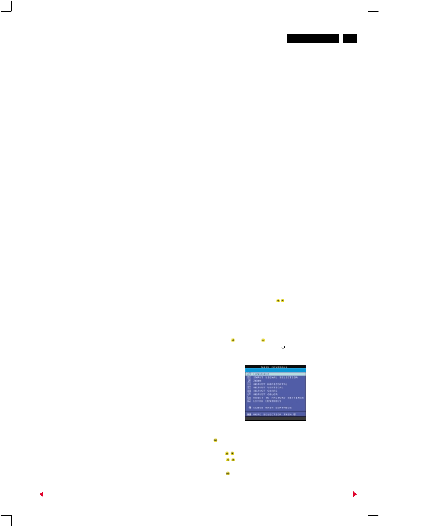
5. To access factory mode:
- Turn off monitor (don't turn off PC)
- Press " " and " " simultaneously on the front
control panel, then press " ",wait till the OSD menu
with characters " factory mode (below OSD menu)" come
on the screen of monitor.
00195
109P V3.08 000601
- If OSD menu disappears on the screen of monitor, press
" " again (anytime), then the OSD menu comes on the
screen again.
- using " " : to select OSD menu.
: to increase or decrease the setting.
- Using " " to confirm the selection.
Back
Forward
Page 2
14
109P2 GS3 CM25
Go to cover page
9
6 To leave factory mode
Electrical Adjustments (Continued)
* After alignment of factory mode, turn off monitor (if you do
not turn off monitor, the OSD menu is always at the factory
mode), then turn on monitor again (at this moment, the
OSD menu goes back to user mode).
TIMER Set OSD display time.
7. Alignment of Vg2 cut-off point, white tracking (OSD
control)
Equipment : 1. Video Test Generator-801GC (Quantum Data)
2. Color-analyzer (Minolta CA-100)
VG2 [(screen), at the bottom of the L.O.T.].
* Apply a video signal in the 1024 x 768 with 68.7 kHz/85 Hz
mode,
select the "full white pattern" (sizes 355 x 265 mm).
* Use color-analyzer (Minolta CA-100) to adjust cutoff and
white uniformity.
OSD R/G/B cut-off and R/G/B gain can be accessed, with
initial data:
°
9300 K
R cutoff = 30%, R gain = 70% (I C)
G cutoff = 30%, G gain = 70% (I C)
B cutoff = 30%, B gain = 70% (I C)
°
6500 K
R cutoff = 30%, R gain = 70% (I C)
G cutoff = 30%, G gain = 70% (I C)
B cutoff = 30%, B gain = 70% (I C)
°
5500 K
R cutoff = 30%, R gain = 70% (I C)
G cutoff = 30%, G gain = 70% (I C)
B cutoff = 30%, B gain = 70% (I C)
Brightness = 50%, Sub-Contrast = 90%, ABL = 50% (I C)
2
2
2
2
2
2
2
2
2
2
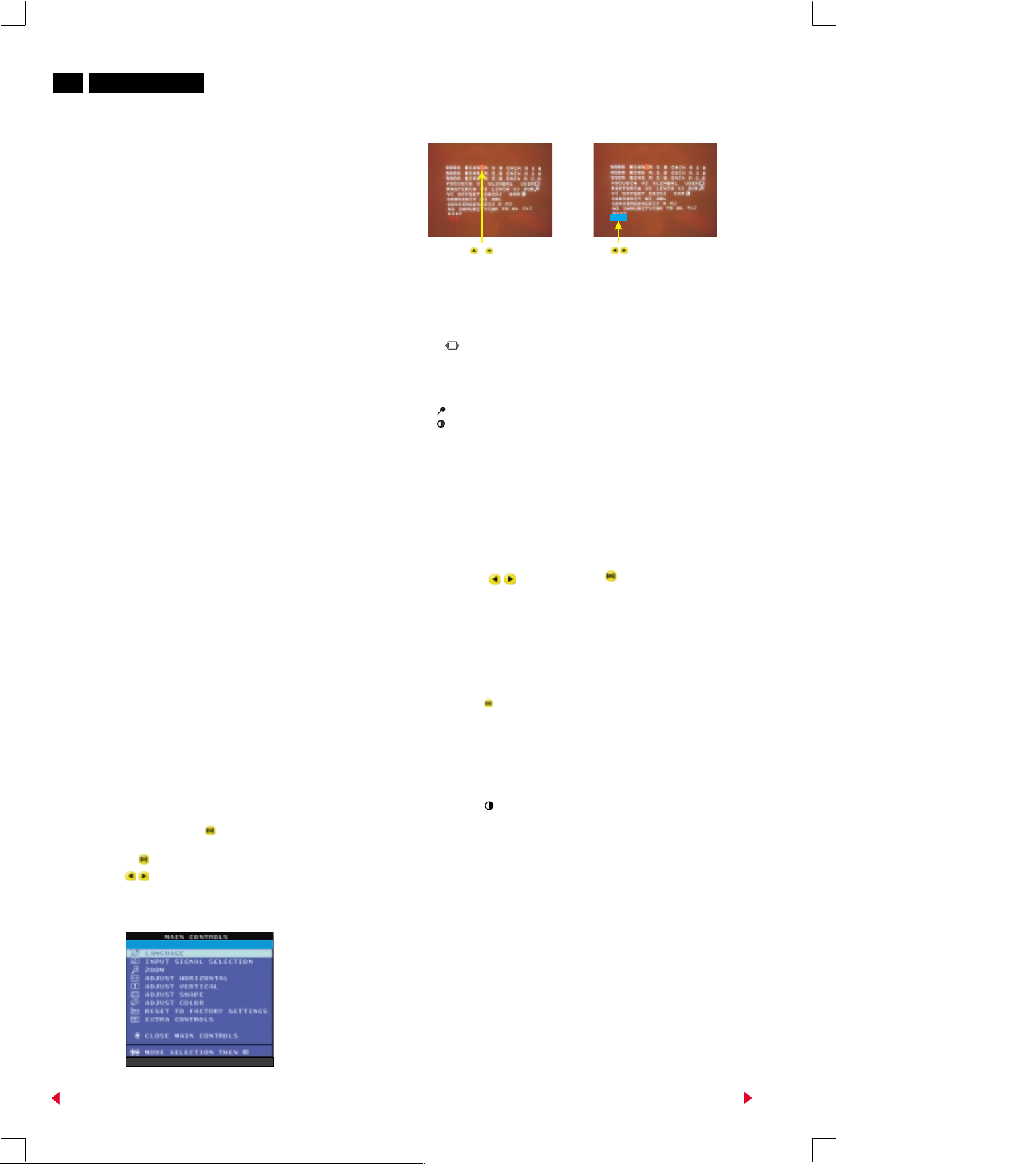
Step 1: To select the character "FACTORY MODE" as shown
in Fig. 2.1, press " " to access the OSD menu for
R/G/B gain & cutoff as shown in Fig. 2.2.
Step 2: Press " " for function selection as shown in Fig 2.3.
Step 3: Use " " to increase or decrease the value as
shown in Fig. 2.3.
.
107
Fig. 2.2
BIASRGB:R(red) G(green) B(blue) cutoff
GAINRGB:R(red) G(green) B(blue) gain
V FOCUS : Vertical Focus
H FOCUS : Horizontal Focus
VLIN BAL : Vertical Linearity Balance
USER : Horizontal size range
RASTER H: Horizontal raster Shift
RASTER V: Vertical raster Shift
HLIN : Horizontal Linearity
V LIN : Vertical Linearity
SUB : Zoom Control range
SUB : Sub Contrast
V OFFSET : Vertical offset
V GAIN : Vertical Gain
ABL : Auto Beam Limit
T CORNER: Corner Correction of TOP
B CORNER: Corner Correction of BOTTOM
CONVERGENCE(V H R):CONVERGENCE Correction of Vertical ,
NS IMPURITY(BR TR BL TL):NS IMPURITY Correction of BOTTOM
Horizontal,Corner (RESERVED).
RIGHT,
TOP LEFT.
TOP BOTTOM LEFT,
Fig. 2.3
RIGHT,
After pressing " " ,then Press " "
7.1 Connect the video input, set brightness control at 50%
and contrast at minimum position (OSD), Vg2 at Minimum
(counter clockwise, and ABL (OSD) at 50% position.
Slowly increase Vg2 voltage until light output is at
0.1 Ft-L +/- 0.01Ft-L (Y=0.1 Ft-L, on the screen of CA-100).
7.2 (The screen of monitor is dark now)
: Press " " to show the OSD menu as shown in Fig. 2.1.
: Select the character "FACTORY MODE" to access the
R/G/B adjustment as shown in Fig. 2.2 and Fig. 2.3.
: Adjust the cutoff of R/G/B to get 9300K
(x=0.283 +/- 0.015, y=0.297 +/- 0.015), and brightness
output at 0.07 +/- 0.01 Ft-L (Y=0.07Ft-L).
7.3 : Press " " to set contrast at maximum (100%).
: Adjust gain of R/G/B to get 9300K
(x=0.283 +/- 0.015, y=0.297 +/-0.015, don't care about
the Y value)
7.4 Apply a small white square 10 x 10 cm pattern, brightness
set to center (50%), and contrast at maximum (100%),
adjust Sub-contrast control (OSD) to reach 32 +/- 2 Ft-L.
Back
00195
109P V3.08 000601
7.5 Apply full white pattern at 9300K, adjust ABL (OSD) to
reach 32+/- 2 Ft-L (contrast at maximum 100%,
brightness at center 50%).
Fig.2.1
Forward
Page 3
Electrical Adjustments (Continued)
109P2 GS3 CM25
Go to cover page
9
15
7.6 : Select the 6500K colour temperature as shown in Fig.
2.2.
: Adjust the R/G/B cutoff and R/G/B gain as shown in
procedure 7.2~7.3 to get
R/G/B cutoff x= 0.313 +/- 0.015
y= 0.329 +/- 0.015
R/G/B gain x= 0.313 +/- 0.015
y= 0.329 +/- 0.015
Y= 28 +/- 2 Ft-L(Adjust Sub-contrast
control (OSD))
7.7 : Select the 5500K colour temperature as shown in Fig.
2.2.
: Adjust the R/G/B cutoff and R/G/B gain as shown in
procedure 7.2~7.3 to get
R/G/B cutoff x= 0.332 +/- 0.015
y= 0.347 +/- 0.015
R/G/B gain x= 0.332 +/- 0.015
y= 0.347 +/- 0.015
Y= 25 +/- 2 Ft-L(Adjust Sub-contrast
control (OSD))
8. Picture geometry setting (factory pre-set modes)
- Apply a video signal with cross-hatch pattern.
- Apply a video signal in the 1024 x 768 with 68.7 kHz/85 Hz
mode.
- Set brightness and contrast controls to their center positions
(OSD control).
9. Focus adjustment
: Apply a video signal in the 1024 x 768 with 68.7 kHz/85 Hz
mode
: Select " @ " pattern.
: Set the brightness at center (50%) and the contrast to 22
FL.
: Adjust focus potentiometers (top of L.O.T.) Focus 1 for
horizontal focus and Focus 2 for vertical focus so that the
picture at 2/3 of the diagonal lines (from center to four
corners) of the displayed screen is as sharp as possible.
10. Loading DDC code
into the DDC IC by EEPROM writer or equivalent method.
a: Service DDC Kit
DDC Module (DDC cable), Part number = 4822 320 12004
DDCV2A.EXE software (3.5" disk), Part number = 3138
106 10065
b: Please refer to Service information 4822 727 21027(4822
727 21038) for using the Service DDC Kit.
The DDC HEX data should be written
8.1 Horizontal geometry (OSD control)
- Adjust the H-width to 355 mm
- Adjust the H-phase to center position.
8.2 Vertical geometry (OSD control)
- Adjust vertical size to 265 mm
- Adjust V-phase to center position.
8.3 Trapezoid distortion (OSD control)
- Adjust the trapezoid to get optimal vertical lines.
8.4 Pincushion (OSD control)
- Adjust the pincushion to get optimal vertical line.
8.5 Parallelogram (OSD control)
- Adjust parallelogram so that vertical lines are vertical or
symmetrically about the center vertical axis.
8.6 Unbalance-pin (OSD control)
- Adjust the unbalance-pin so that that vertical border lines
are aligned symmetrically.
8.7 Rotation (OSD control)
- Adjust picture so that vertical tilt is less than +/- 0.5mm.
8.8 Top/Bottom corner(control)
- Adjust the top/bottom corner control to get optimum corner
geometry.
8.9 Store the preset results by selecting the "exit" (OSD
control).
8.10 Repeat the procedure 8.1 to 8.9 until all the preset
timings have been adjusted completely
Back
Forward
 Loading...