

Page 1

8
105E CM23 GSIII
9 Go to cover page
Electrical Instructions
0. General:
When carrying out the electrical setting, in many cases a video
signal must be applied to the monitor. A computer with :
- "ATI VGA1024" interface card
- PGA1024 (4822 212 30916)
- PGA1280 (4822 212 30917)
are used as the video signal source. The signal pattern are selected
from the "service test software" package. see user guide 4822 727
19896 (ATI 1024), or 4822 727 20273 (PGA 1280).
0.1 Factory preset timing mode
- Installation instruction for the ATI card:
- Place the ATI interface card into the computer.
- Select the "vsetup" file from the utility disk belonging to the card.
- Select "8 bits" or "16 bits" rom operation depending on your
computer type.
- Select "analog monitor".
- Select the monitor type from video ROM BIOS.
- Select "MAGNAVOX CM5000" for the resolutions:
Reolution H.freq./V.freq. H. V.
640 x 480 31.5 kHz/70 Hz - +
640 x 480 31.5 kHz/60 Hz - 640 x 480 37.5 kHz/75 Hz - 800 x 600 46.9 kHz/75 Hz + +
800 x 600 53.7 kHz/85 Hz + +
1024 x 768 48.3 kHz/60 Hz - -
2. EHT voltage (3540)
- Connect a dc voltmeter between capacitor 2643 joint and ground.
- Apply a video signal in the 640 x 480 with 31.5 kHz/60 Hz mode.
- Select the "crosshatch" pattern. Adjust trimming pot-meter 3540
until the DC voltmeter reads : 66.5 +/- 0.2V (for PHILIPS CRT),
But 66.5V for CPT CRT
3. Monitor the following auxiliary voltages
+12V source across C2158 +12.7V +/- 0.5 VDC
- 12V source across C2162 - 12.7V +/- 0.5 VDC
+8V source across C2172 +8.0V +/- 0.4 VDC
+6V source across C2164 +6.2V +/- 0.3 VDC
-178V source across C2647 -178V +/- 8.0 VDC
+180V source across C2153 +183V +/- 1.5 VDC
+5V source across C2168 +5.0V +/- 0.25VDC
+80V source across C2156 +81.0 V +/- 0.5 VDC
4. General conditions for alignment
4.1 During all alignments, supply a distortion free AC mains voltage
to set via an isolating transformer with low internal impedance.
4.2 Align in pre-warmed condition, at least 30 minutes warm-up with
nominal picture brightness.
4.3 Purity, geometry and subsequent alignments should be carried
out in magnetic cage with correct magnetic field.
Northern hemisphere : H=0, V=450 mG, Z=0
Southern hemisphere : H=0, V=-500 mG, Z=0
Equatorial Support : H=0, V=0 mG, Z=0
- Reboot your computer, again.
- Put the floppy diskette containing the service test software package
in the computer and select the test pattern indicated for the
service setting.
0.2 With normal VGA card:
If not using the ATI card during repair or alignment, The service
engineer also can use this service test software adapting with normal
standard VGA adaptor and using standard VGA mode
640 x 480, 31.5kHz/60Hz (only) as signal source.
0.3 AC/DC measurement:
The measurements for AC waveform and DC figure is based on 640 x
480 31.5 kHz / 60 Hz resolution mode with test pattern gray scale.
1. B+ Supply voltage (3178), 81 VDC
- Set the brightness front control and the contrast front control to
minimum.
- Set the trimming pot-meters 3178/3540 in the mechanical midposition (this is a pre-setting).
- Connect a DC voltmeter between capacitor 2156 joint and ground.
- Switch on the monitor.
- Apply a video signal in the 640 x 480 with 31.5 kHz/60 Hz mode.
- Select the "crosshatch" pattern.
- Adjust trimming pot-meter 3178 until the DC voltmeter reads 81 V
+/- 0.2V.
4.4 All voltages are to be measured or applied with respect to
ground.
Note: Do not use heatsink as ground.
4.5 Adjust brightness controls to center position except for contrast
control which should be set to MAX.
5. To access Factory Mode:
1. When "shift" LED is off, control is at 1st level, and when LED is on,
control is at 2nd level.
2. "Shift" LED will flash 0.1 second at the time when function keys (e.g.
H-Shift, H-Size,...,etc.) are pressed, and it should flash continuously
when adjusting "+" or "-" is at end of range. Releasing "+" or "-" key,
all adjusted values will be stored automatically after 10 seconds.(at
user Mode).
3. Factory preset mode entry, in power on status pressed "H-shift" and
"V-size"simultaneously at 1st level. After 2 seconds the shift led will
flash 3 times then the u-controller will entry factory mode.
( turn off power and then on to return to user mode)
4. "Power down overrule" is only functional in power saving status and
will be reset by switching off power.
5. At factory adjust mode, Press Shift key( shift LED on) then press V-
size, the modified data will be stored in factory preset area on
EEPROM and shift LED will flash two times.
6. At service, please entry Factory mode (pressing H-Shift and V-size
simultaneously) first before using service factory alignment tools or
auto-alignment to perform factory alignment.
3Back
Forward4
Page 2

Electrical Instructions (Continued)
105E CM23 GSIII
9 Go to cover page
9
6. Picture geometry setting for factory pre-set mode
6.1 General
- Pre-set contrast front control and brightness front control
to mid-position.
6.2 53.7 kHz 85 Hz mode
(apply crosshatch pattern in 800 x 600 with 53.7 kHz/85 Hz mode)
6.3 Alignment of Horizontal and vertical geometry
6.3.1 Adjust the picture width to 270 mm.
6.3.2 Adjust the H-phase to center position.
6.3.3 Adjust the picture height to 202 mm.
6.3.4 Adjust V-Position to center
Adjust/Trapezium/pincushion
6.3.5 Adjust picture tilt I CBUS for correct top/bottom lines.(Optional)
2
(picture tube should be mounted without tilt w.r.t. cabinet)
6.3.6 Adjust the corner by I C to straight vertical lines of the left and
2
right edge.
6.3.7 Adjust the parallelogram by I C to get optimum vertical line.
6.3.8 Adjust the unbalance pin by I C to get optimum vertical line.
6.3.9 Adjust the unbalance Vertical linearity balance by I C to get
2
2
2
optimum vertical linearity balance.
6.3.10 Adjust the unbalance Vertival linearity by I C to get optimum
2
vertical linearity.
6.4 Adjust size / centering / trapezium / pincushion / parallelogram
of all other preset modes via I C bus
2
7.6 Set 7099 TDA4886 contrast value at 63. (dec)
7.7 Set CA100 high R,G,B scale 100 = 50 +/- 1FL (contrast at Max.)
7.8 Adjust R,B gain so that blue and green have the same readings
as red on high brightness scale.
7.9 Set contrast at minimum and repeat 7.5, 7.6, 7.7, 7.8 until RGB
three guns get same readings on low and high brightness scale.
7.10 Apply full white at contrast and ABL via I2C to reach 30 +/- 1FL
(contrast at Max.)
7.11 Check full white at contrast and brightness at minimum, the
foreground shall be extinguished.
8. Focus adjustment
Apply a signal of"@"character. at 53.6 kHz/85 Hz mode set the
brightness to mid-position , contrast to max - position and adjust
the focus for optimal sharpness in the area within 2/3 from the
screen center.
9. Loading DDC code
Hard ware DDC(with 7807 model)
The DDC HEX data(refer sheet 190) should be written into the
EEPROM (7807) by EEPROM writer or equivalent method.
Software DDC(with 7807 model)
The DDC HEX data(refer sheet 190) should be written into the
EEPROM (7806) Page 2,0~127 bytes by EEPROM writer or
equivalent method.
a: Service DDC Kit
DDC Module (DDC cable), Part number = 4822 320 12004
DDCV2u.EXE software (3.5" disk), Part number = 4822 711 00024
b: Please refer to Service information 4822 727 21995 for using
the Service DDC Kit.
7. Alignments of VG2 cut-off point, white tracking:
7.1 External degaussing
7.1.1 Remove ferromagnetic measuring equipment, iron table, etc.)
in the neighborhood of the apparatus within the half meter.
7.1.2 positioned in the E-W direction, set has to be degaussed
externally with coil 7122 704 18001(220V)
7.1.3 Slowly increase the distance between the picture tube and
degaussing coil, keep the coil in parallel with the screen of CRT .
When the distance is more than 2m, then turn off the degaussing
current.
7.2 Apply 53.7Khz/85Hz 800 x 600 mode with 700mV 50x50mm
white block pattern.
7.3 Set brightness control at center click and contrast at Maximum
Set R,G,B cut-off at 50% (EEPROM preload value)
R,G,B gain at 28(dec) (EEPROM preload value)
ABL at 50% (EEPROM preload value)
2
Via I C bus , set 7099 TDA 4886 contrast to minimum
7.4 With the help of a factory calibrated color analyzer CA100
set LOW R,G,B scale 100+0.12FL, X=281, y=311.
Adjust VG2(screen) until brightness gun at 100 on low brightness
scale.
7.5 Adjust the R,G,B cut - off for all gun readings to get 100 on low
brightness scale.
3Back
Forward4
Page 3
10
105E CM23 GSIII
9 Go to cover page
10. Purity adjustment
- Make sure the monitor is not exposed to any
external magnetic field.
- Produce a full red pattern on the screen, adjust the
purity magnet rings on the PCM assy (on CRT) to
obtain a complete field of the color red. This is done
by moving the two tabs (2-pole) in such a manner
that they advance in an opposite direction but at
the same time to obtain the same angle between
the two tabs, which should be approximately 180
degree.
- Check by full green pattern and full blue pattern
again to observe their respective color purity.
11. Static convergence
Electrical Instructions(continued)
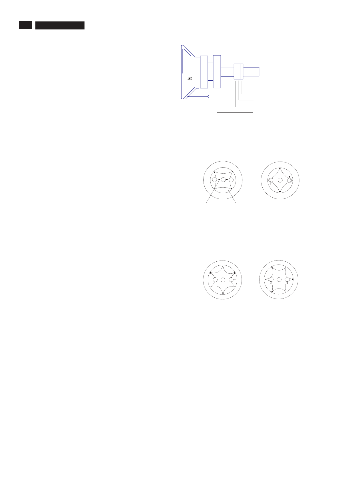
2-pole purity magnet
6-pole convergence magnet
4-pole convergence magnet
Deflection Yoke
Introduction
Slight deviation in the static convergence can be
corrected by using two permanent pairs of magnets
which are fitted around the neck of the CRT. These
are the 4-pole magnet and the 6-pole magnet.
The 4-pole magnet move the outermost electron
beams (R and B) parallel in the opposite direction
from the other. The 6-pole magnet moves the
outermost electron beam (R, B and G) parallel in the
opposite direction from the other.
The magnetic field of the above magnets do not affect
the center of the CRT neck.
Setting
- Before the static convergence setting can be made,
the monitor must be switched on for 30 minutes.
- The focus setting must be made correctly.
- Signal: 640 * 480, 31.5 kHz/60 Hz mode.
- Set the tabs of the 4-pole magnet in the neutral
position. This is when the tabs are opposite one
another. In this position the magnets do not affect the
deflection of the R and B electron beams.
- Set the tabs of the 6-pole magnet in the neutral
position. This is when the tabs are opposite one
another. In this position the magnets do not affect the
deflection of the R, B, and G electron beams.
- First set the 4-pole magnet optimally.
- Then set the 6-pole magnet optimally.
- If the convergence is not now optimal, then adjust to
the optimal setting with the 4-pole magnet and then with
the 6- Pole magnet again.
- Set the tabs of the 6-pole magnet in the neutral
position. This is when the tabs are opposite one
another. In this position the magnets do not affect the
deflection of the R, B, and G electron beams.
- First set the 4-pole magnet optimally.
- Then set the 6-pole magnet optimally.
- If the convergence is not now optimal, then adjust to
the optimal setting with the 4-pole magnet and then
with the 6- pole magnet again.
4-pole Beam motion producced by the
4-pole convergence magnet
S
B
N
Beam displacement
direction
6-pole
N
G
R
S
N
B
Magnetic flux
lines
Beam motion producced by the
6- pole convergence magnet
N
S
B
N
S
R
G
N
S
S
B
N
G
S
S
G R
S
N
N
S
R
N
3Back
Forward4
Page 4
Instructions for Alignment KIT
1.Introduce
The alignment kit is designed for CPU controller to adjust the screening size, shift, geometric,color temperature,..etc
of monitor control function. and other function depend on your need.
2. Alignment environments :
- Windows 95 for alignment software (I2C-200.EXE and I2C-200.R00)
- Access Factory Mode of IBM C50R Monitor before adjustment
by using "I2C-200.EXE and I2C-200.R00".
105E CM23 GSIII
9 Go to cover page
11
3.Installation
3.1 The followings are necessary for Alignment KIT application.
- An Intel 486 (or above) PC or compatible, Windows 95
- Pattern generator or the other PC
- The 15-pin D-sub connector of the signal cable(3 rows) x2
- The 25 pin connector of the printer cable (2 rows)x1
- Alignment KIT of IBM C50R , Part number = 4822 310 11317 (= 4822 724 40881)
- I2C-200.EXE (3.5" Floppy Disk), Part number = 4822 711 00056 (= 4822 724 30290)
- I2C-200.R00 (3.5" Floppy Disk), Part number = 4822 711 00057 (= 4822 724 30300)
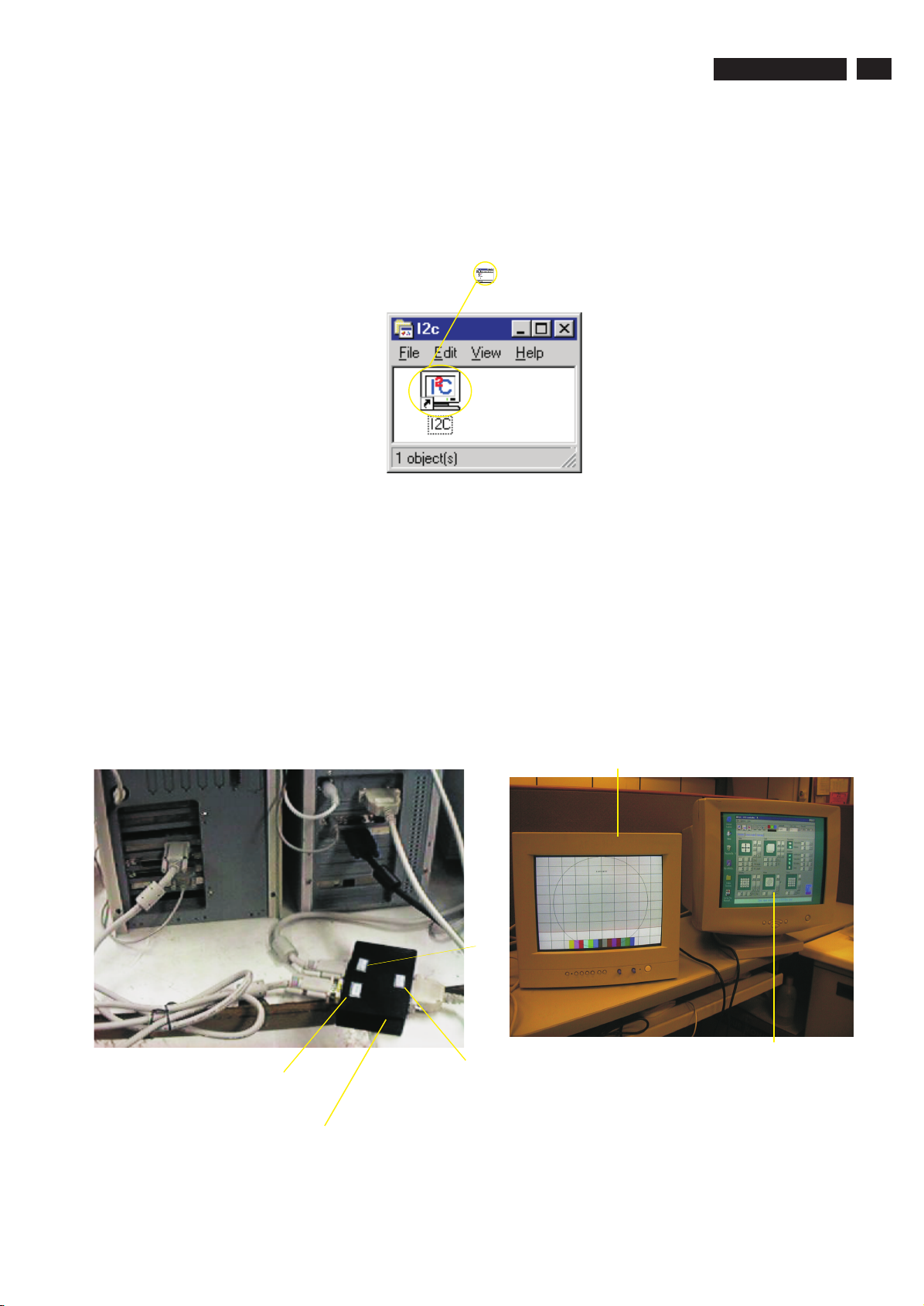
4. Connection, see figure as below.
Monitor - IBM C50R
3Back
To PC ( the other PC)
or pattern generator
To Printer (main PC,
with I2C-200.EXE)
(Alignment Kit : code number is 4822 310 11317)
To monitor - IBM C50R
I2C pattern for adjustments
Forward4
Page 5
12
105E CM23 GSIII
Instructions for Alignment KIT
9 Go to cover page
In "MS DOS environment", make a sub-directory "I2C-200" in your Hard Disk "C",
then copy "I2C-200.EXE" and "I2C-200.R00" into your sub-directory.
1. C:\MD I2C-200 , press "Enter"
2. C:\CD I2C-200 , press "Enter"
Bring up --> C:\I2C-200>
3. Insert disk 1 (I2C-200.EXE) into Drive A
4. C:\I2C-200>COPY A:\I2C-200.EXE , press "Enter"
5. Take disk 1 out from Drive A
6. Put disk 2 (I2C-200.R00) into Drive A
7. C:\I2C-200>COPY A:\I2C-200.R00 , press "Enter"
8. C:\I2C-200>I2C-200 , press "Enter"
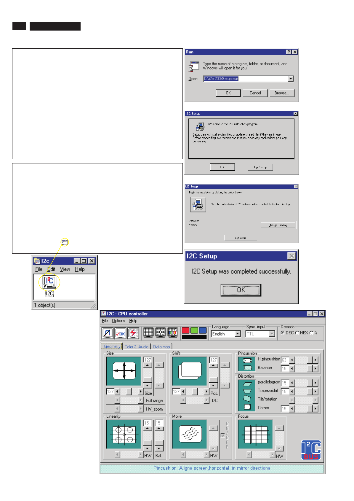
In "MS Windows 95" environment:
1. Open: C:\I2C-200\Setup.exe
(As Fig. 1)
2. Click "OK" of Fig.1, bring up "Fig. 2"
3. Click "OK" of Fig. 2, bring up "Fig. 3"
4. Click "ICON" of Fig. 3, bring up "Fig. 4"
5. Click "OK" of Fig. 4, bring up "Fig. 5"
Fig. 1
Fig. 2
Fig. 3
6. Double-click "ICON " of Fig. 5 to bring up
Main Menu of CPU controller as "Fig. 6".
Fig. 5
1. Click the "Options", and then
point to "Command code setup..."
2. Click "Command code setup",
bring up Fig. 7.
Fig. 6
Fig. 4
3Back
Forward4
Page 6
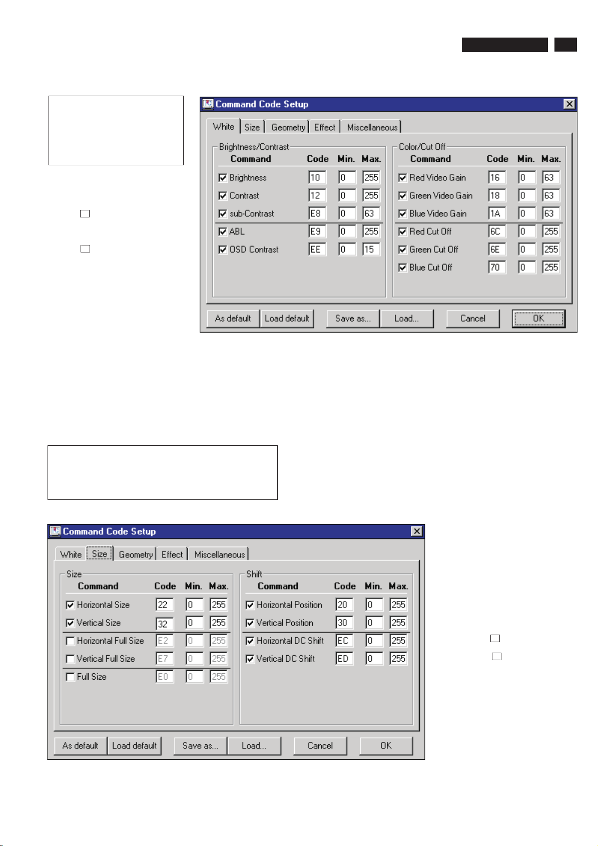
Brightness/Contrast
*change the Max. value from 255 to
63 as below.
Brightness Max. value 63
Contrast Max. value 63
Disable sub-Contrast ----------------->
Disable OSD Contrast --------------->
Instructions for Alignment KIT
105E CM23 GSIII
9 Go to cover page
Fig. 7
13
Click "Size", bring up Fig. 8.
Change the Max. value of Vertical Size from "255" to "127"
Change the Max. value of Vertical Position from "255" to "127"
Fig. 8
<--------Disable Horizontal DC Shift
<--------Disable Vertical DC Shift
3Back
Forward4
Page 7
14
105E CM23 GSIII
9 Go to cover page
Fig. 9
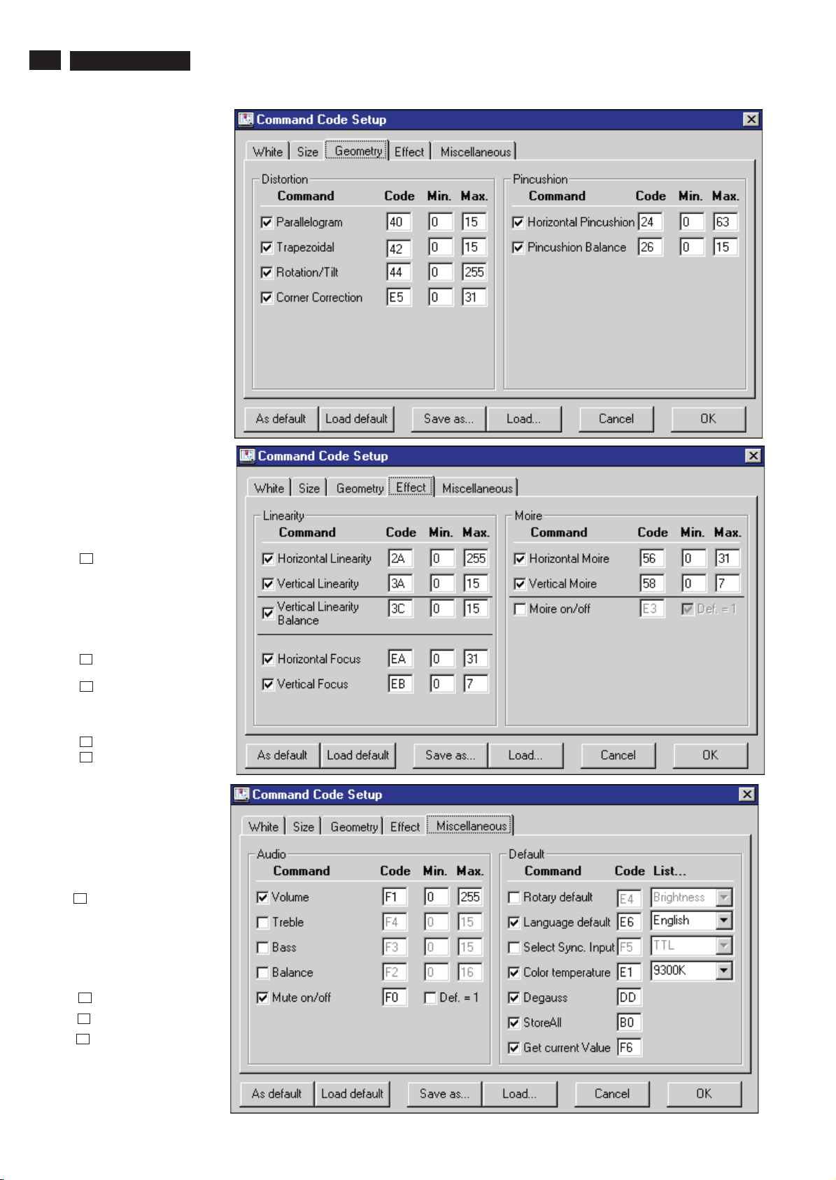
Click "Geometry", bring up Fig. 9.
Change the Max. value of
Corner Correction
from "31" to "15" ------------------------->
Fig. 10
Instructions for Alignment KIT
Click "Effect", bring up Fig. 10.
Disable Horizontal Linearity----->
Disable Horizontal Focus---------->
Disable Vertical Focus------------->
Disable Horizontal Moire
Disable Vertical Moire
Fig. 11
Click "Miscellaneous", bring up Fig. 11.
Disable Volume---------------------->
Disable Mute on/off----------------->
Disable Language default--------->
Disable Degauss-------------------->
3Back
Forward4
Page 8
Instructions for Alignment KIT
After setting of White, Size, Geometry and Effect,
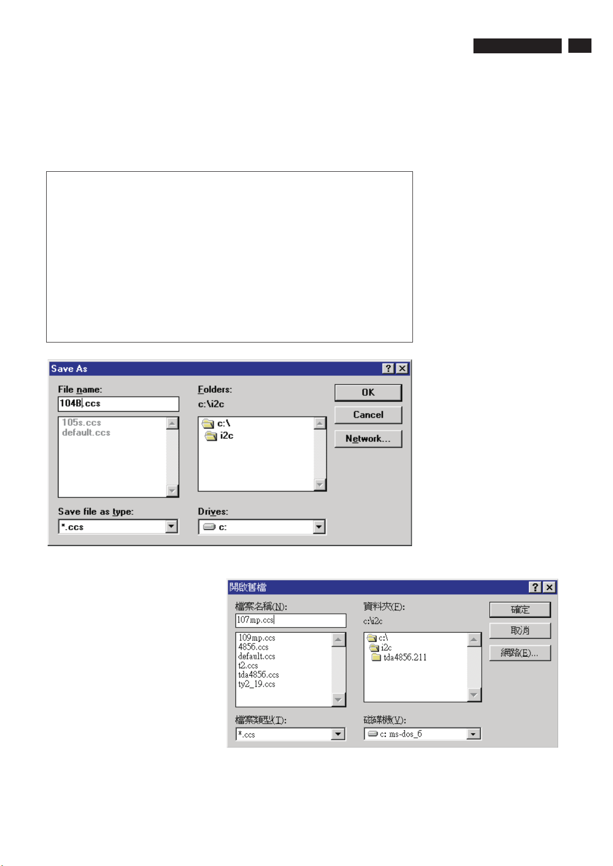
1. Click "Save as", then bring up Fig. 12.
2. Fill in "File name", -- "104B.ccs" or "105S.ccs" --
3. Click "OK", then the default value of 104B or 105S will be saved to sub-directly "i2c".
The default values of 104B/105S are as below for Factory mode alignment.
105E CM23 GSIII
9 Go to cover page
15
size H Max. value 255 pincushion H.pin Max. value 63
V Max. value 127 Pin. bal. Max. value 15
shift H Max. value 255 Distortion parallel Max. value 15
V Max. value 127 Trapezoidal Max. value 15
Linearity Vert. lin. Max. value 15 Corner Max. value 15
Vert. LIn.Bal Max. value 15
Color
Brightness Max. value 63
Contrast Max. value 63
ABL Max. value 255
RGB gain RGB cutoff
RED Max. value 63 RED Max. value 255
GREEN Max. value 63 GREEN Max. value 255
BLUE Max. value 63 BLUE Max. value 255
Fig. 12
1. Click the "File", and then
point to "Load CCS".
Click "Load CCS", Bring up Fig. 13.
2. Click "105s.ccs or 104b.ccs".
Click "OK", then bring up the
default setting for alignment
as Fig. 6.
** NEXT TIME **
Load 105s.ccs or 104b.ccs
for Electrical Alignment directly.
3Back
Fig. 13
Forward4
 Loading...