

Page 1

X--RAY GENERATION
LIST OF DOCUMENTATION IN THIS BINDER:
SUBSYSTEM MANUAL OPTIMUS RAD
UNIT MANUAL Converter R/F
○ UNIT MANUAL Surge Arrester WN
○ UNIT MANUAL Extension set for an additional tube assembly WG / GWB
○ UNIT MANUAL 26 V DC / 230 V AC Adapter
○ UNIT MANUAL Handswitch for OPTIMUS
○ UNIT MANUAL Extension of Photo Pick-Up OPTIMUS (SEV)
○ UNIT MANUAL Mains group EWD
Note: indicated document present
LIST OF ALL BINDERS FOR X--RAY GENERA
-- SUBSYSTEM MANUAL OPTIMUS RAD (this binder)
TION:
4512 984 28171 REV AB
OPTIMUS_RAD_28171AB_01
E 2004 Philips Medical Systems
ALL RIGHTS RESERVED
0.1
Page 2

Philips Medical Systems
OPTIMUS RAD
W
SERVICE MANUAL
742
SUBSYSTEM
INTRODUCTION AND TECHNICAL DATA
INSTALLATION
1
2
9890 000 0218.
FAULT FINDING
REPLACEMENT
PROGRAMMINGS
ADJUSTMENTS
3
4
5
6
358J92
CAN-controlled X-ray generator of the converter type
DMC Hamburg
Printed in Hamburg, Germany
E 2004 Philips Medical Systems
ALL RIGHTS RESERVED
ACCEPTANCE
SERVICE INFORMATION
PARTS LIST
SCHEMATIC DRAWINGS
7
8
P
Z1-
4512 984 28171 REV AB 1
OPTIMUS_RAD_28171AB_r eg
WIRING DIAGRAMS
Z2-
Page 3

OPTIMUS RAD
SERVICE MANUAL -- SUBSYSTEM
OPTIMUS RAD Author: T. Frenscheck
Type No: 9890 000 0218x
Techn. No: Basis 4512 104 70625
Release: 3.6
In case there are any questions concerning this manual,
please send this LOPAD via fax to 49/(0)40/5078 2481
File: OPTIMUS_RAD_28171AB
List of pages and drawings (LOPAD) Manual Order No: 4512 984 28171
released: 10/2004
0.1
1
3.1
3.2
_________________________________________
_________________________________________
1--0.1 ... 0.2 (e/04.0)
1--1 ... 15 (e/04.0)
Z--1.1 (01.0) A4 4512 982 0092.
Z--1.2 (01.0) A4 4512 982 0092.
Z--1.3 (01.0) A4 4512 982 0099.
Z--6.1 (01.0) A4 4512 982 0099.
Z--7.1 (01.0) A3 4512 982 0092.
Z--7.2 (01.0) A3 4512 982 0092.
Z--7.3 (01.0) A3 4512 982 0092.
Z--7.4 (04.0) A3 4512 982 0092.
Z--7.10 (01.0) A3 4512 982 0010.
_________________________________________
2--0.1 ... 0.2 (d/04.1)
2--1 ... 66 (d/04.1)
2Z--2.0 3x (01.0) A4 4512 983 05591
2Z--2.2 (a/01.0) A4 4512 983 0561 1
2Z--2.4 (a/01.0) A4 4512 983 05631
2Z--2.5 (a/01.0) A4 4512 983 05641
2Z--2.6 (01.0) A4 4512 983 05651
2Z--2.8 (01.0) A4 4512 983 05671
2Z--2.9 (01.0) A4 4512 983 05681
2Z--2.10 (01.0) A4 4512 983 05691
2Z--3 (97.0) A3 4512 983 05721
2Z--4 (97.0) A4 4512 983 05771
2Z--5 (97.0) A4 4512 983 05731
2Z--10 (a/02.0) A3 4512 983 05831
_________________________________________
3--0.1 (c/04.1)
3--1 ... 88 (c/04.1)
3Z--1 (a/03.0) A4 OPTIMUS R/F
3Z--21 (97.1) A4 OPTIMUS R/F
_________________________________________
4--0.1 (c/04.1)
4--1 ... 27 (c/04.1)
_________________________________________
5Z--1 (b/04.0) A3 OPTIMUS R/F
5Z--2 (c/04.0) A3 OPTIMUS R/F
_________________________________________
6--0.1 (c/04.0)
6--1 ... 14 (c/04.0)
_________________________________________
7--0.1 (b/04.0)
7--1 ... 4 (b/04.0)
_________________________________________
8--1 (00.0) FCO-- Checklist
8--2 (00.0) FCO-- Checklist
_________________________________________
4512 984 28171 REV AB
OPTIMUS_RAD_28171AB_l opad
E 2004 Philips Medical Systems
ALL RIGHTS RESERVED
3.1
Page 4

Z0--1 (02.0)
Z1--1.1 (04.0) A3 OPTIMUS R/F
Z1--1.2 (04.0) A3 4512 983 05751
Z1--2.1 (04.0) A3 4512 983 05761
Z1--2.1.1 (04.0) A3 4512 983 05951
Z1--2.2 (04.0) A3 4512 983 05941
Z1--2.2.1 (04.0) A3 4512 983 05961
Z1--2.3 (04.0) A3 OPTIMUS R/F
Z1--3.3 (a/04.0) A3 OPTIMUS R/F
Z1--4.1 (a/04.0) A3 OPTIMUS R/F
Z1--4.2 (04.0) A3
Z1--5.1 (04.0) A3 4512 983 06551
Z1--6 (04.0) A3 4512 983 05531
Z1--11.1 (a/04.0) A3 4512 983 05521
Z1--11.2 (96.0) A4 OPTIMUS R/F
Z1--12 (a/04.1) A3
Z1--13.2 (d/04.1) A3 OPTIMUS R/F
Z1--14.1 (b/98.0) A3 4512 983 05541
Z1--14.2 (c/97.1) A3 4512 983 05551
Z1--15.1 (97.0) A3 4512 983 05571
_________________________________________
Z0--2 (02.0)
OPTIMUS RAD
Z2--1.0 (96.0) A4 OPTIMUS R/F
Z2--1.1 (b/99.0) A3
Z2--1.2 (b/99.0) A3
Z2--1.3 (a/04.0) A3
Z2--2.1 (a/96.0) A3
Z2--2.2 (a/96.0) A3
Z2--2.3 (94.0) A3
Z2--5.1 (b/04.0) A3 OPTIMUS R/F
Z2--5.2 (b/04.0) A3 4512 983 0551 1
Z2--5.3 (a/04.0) A3 OPTIMUS R/F
Z2--5.4 (02.0) A3 OPTIMUS R/F
Z2--12 (a/04.0) A3
Z2--13 (d/00.0) A3 OPTIMUS R/F
Z2--14.1.1 (a/99.0) A3
Z2--14.1.2 (a/99.0) A3
Z2--14.2 (a/04.0) A3 OPTIMUS R/F
Z2--14.3 (a/04.0) A3 OPTIMUS R/F
Z2--15.1 (97.0) A3 4512 983 05741
Z2--16 (97.0) A3 OPTIMUS R/F
Z2--17 (97.0) A3 OPTIMUS R/F
_________________________________________
3.2
E 2004 Philips Medical Systems
ALL RIGHTS RESERVED
4512 984 28171 REV AB
OPTIMUS_RAD_28171AB_l opad
Page 5

OPTIMUS RAD
1. Product information 1--1..................................................
1.1. Applications 1--1..........................................................
1.2. Options 1--1..............................................................
1.2.1. Hardware options 1--1......................................................
1.2.2. Software options 1--2......................................................
2. Compatibility 1--3........................................................
2.1. Generator components 1--3.................................................
2.2. Tubes 1--3................................................................
2.3. Five-field bucky chamber 1--3...............................................
INTRODUCTION AND TECHNICAL DATA
INTRODUCTION AND TECHNICAL DATA
Contents
TEXT
Contents 1--0.1............................................................
3. Mechanical data 1--4......................................................
4. Environmental data 1--5...................................................
4.1. Electrical environment 1--5..................................................
4.2. Climatic conditions 1--5.....................................................
4.3. Emission 1--5.............................................................
5. Electrical data 1--6........................................................
5.1. Power data and mains conditions 1--6........................................
5.2. Power supply for applications 1--7...........................................
5.3. Operating data 1--7........................................................
5.4. Power supply 1--8.........................................................
5.4.1. Type of power supply 1--8..................................................
5.4.2. Calculating the mains resistances 1--9........................................
5.4.3. Earth-leakage circuit-breaker 1--10............................................
5.4.4. Emergency--OFF device 1--10................................................
6. Tools 1--11................................................................
7. Traceable items 1--12......................................................
8. Preparation 1--13..........................................................
8.1. Installation material 1--13....................................................
8.2. Cables 1--13...............................................................
8.3. Manpower 1--14............................................................
9. Planned maintenance 1--15.................................................
OPTIMUS RAD (e/04.0)
OPTIMUS_RAD_1_e040_inh
2004 Philips Medical Systems
ALL RIGHTS RESERVED
1--0.1
Page 6

OPTIMUS RADINTRODUCTION AND TECHNICAL DATA
DRAWINGS
Generator cabinet Z--1.1......................................................
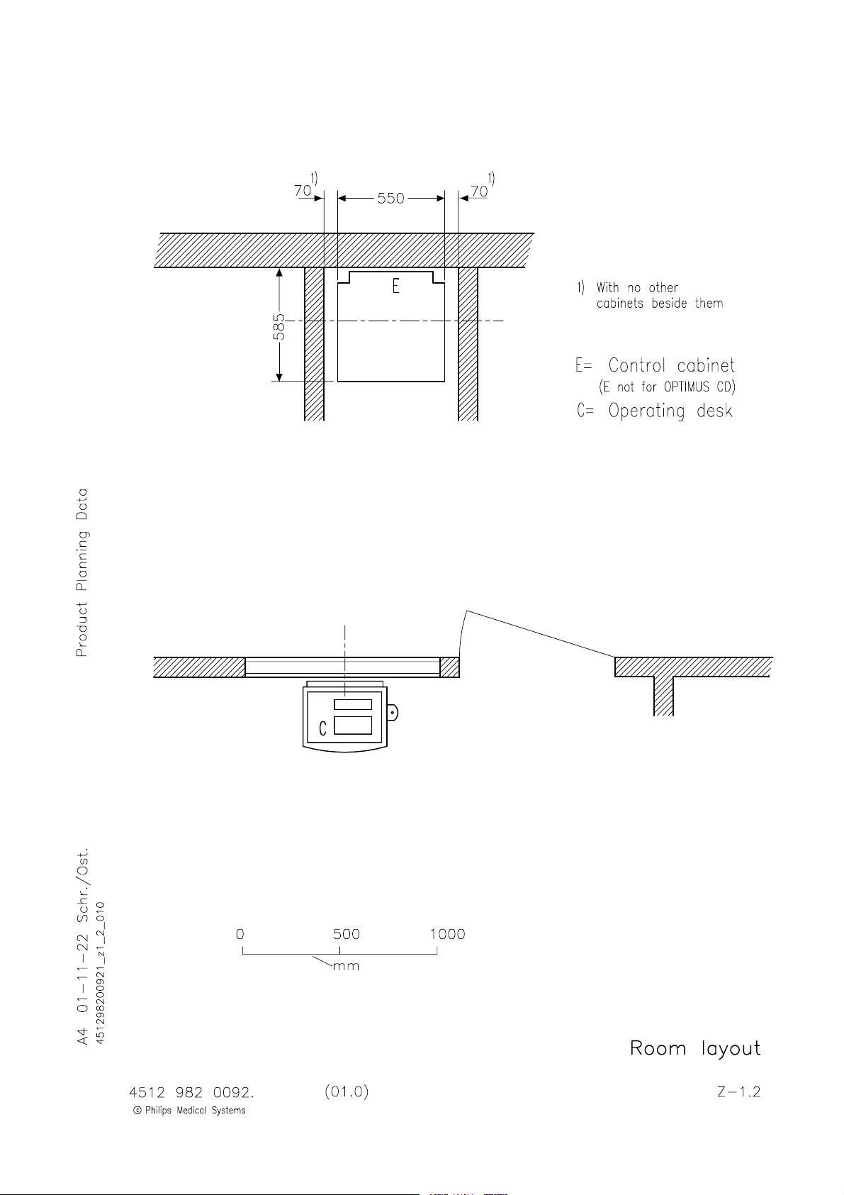
Room layout Z--1.2...........................................................
Operating panel Z--1.3........................................................
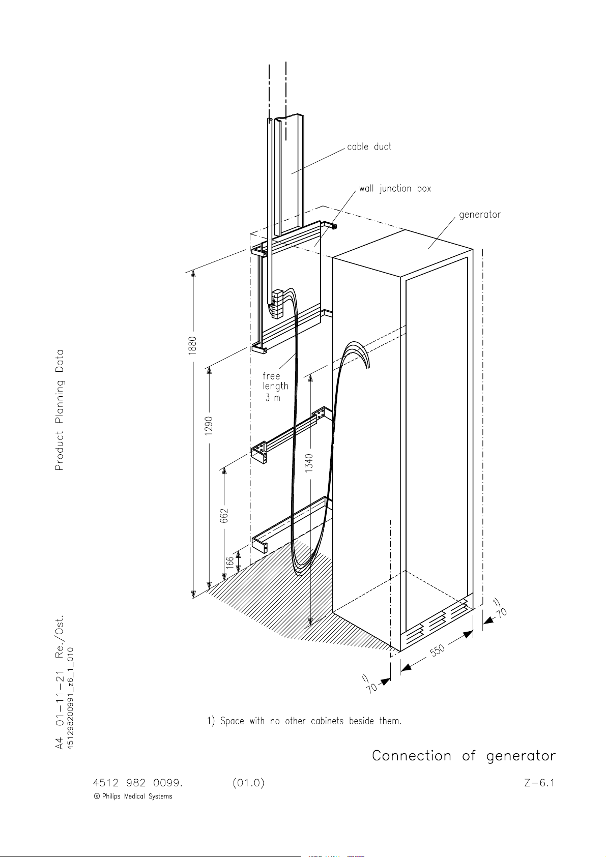
Connection of generator Z--6.1................................................
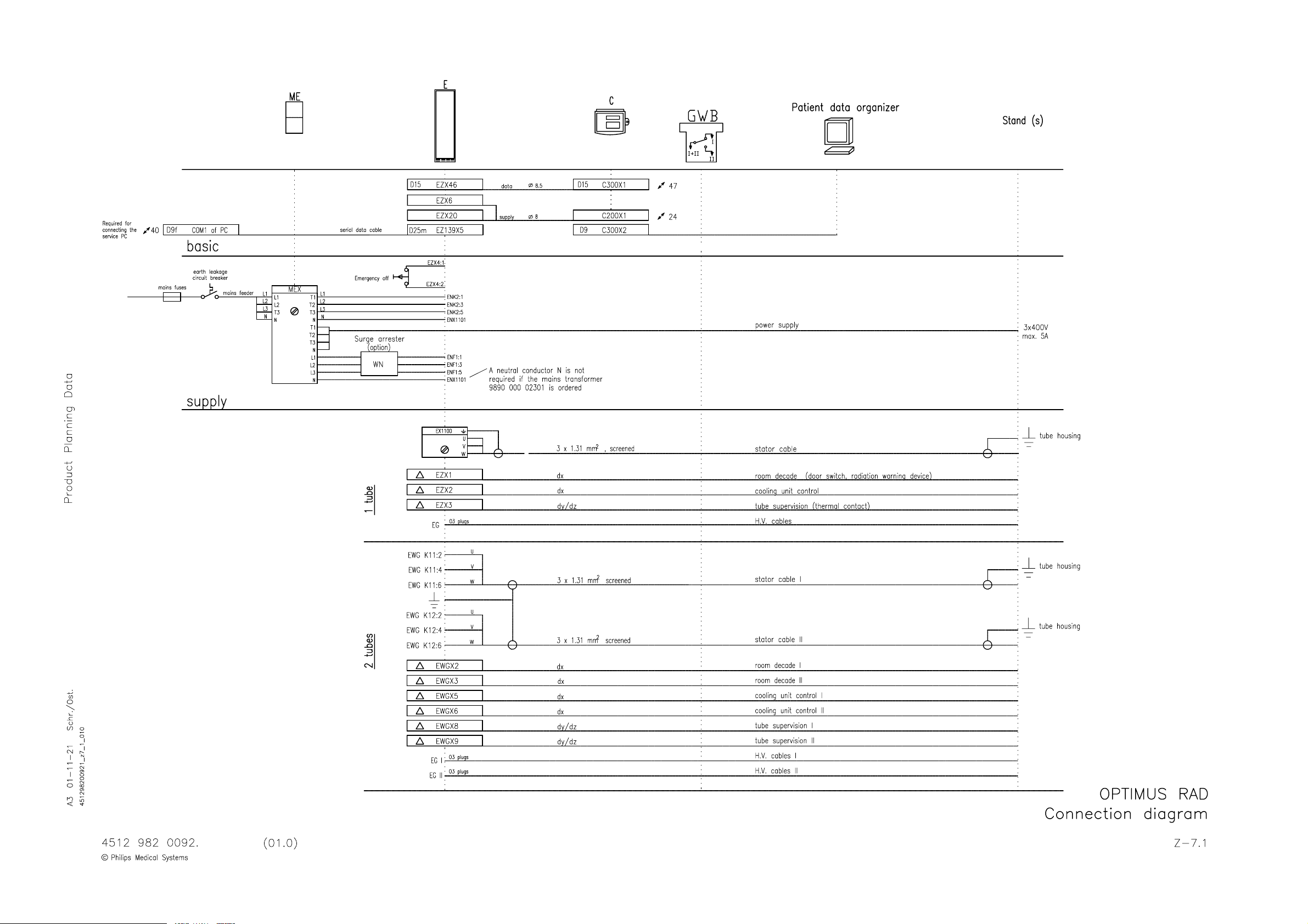
Connection diagram 1Z--7.1...................................................
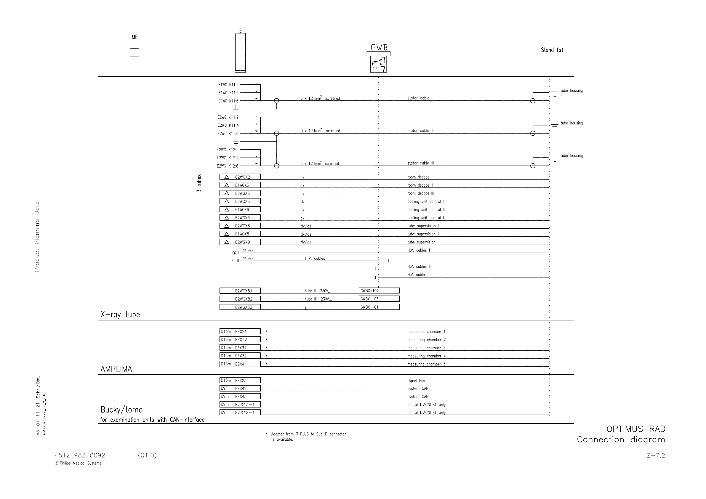
Connection diagram 1Z--7.2...................................................
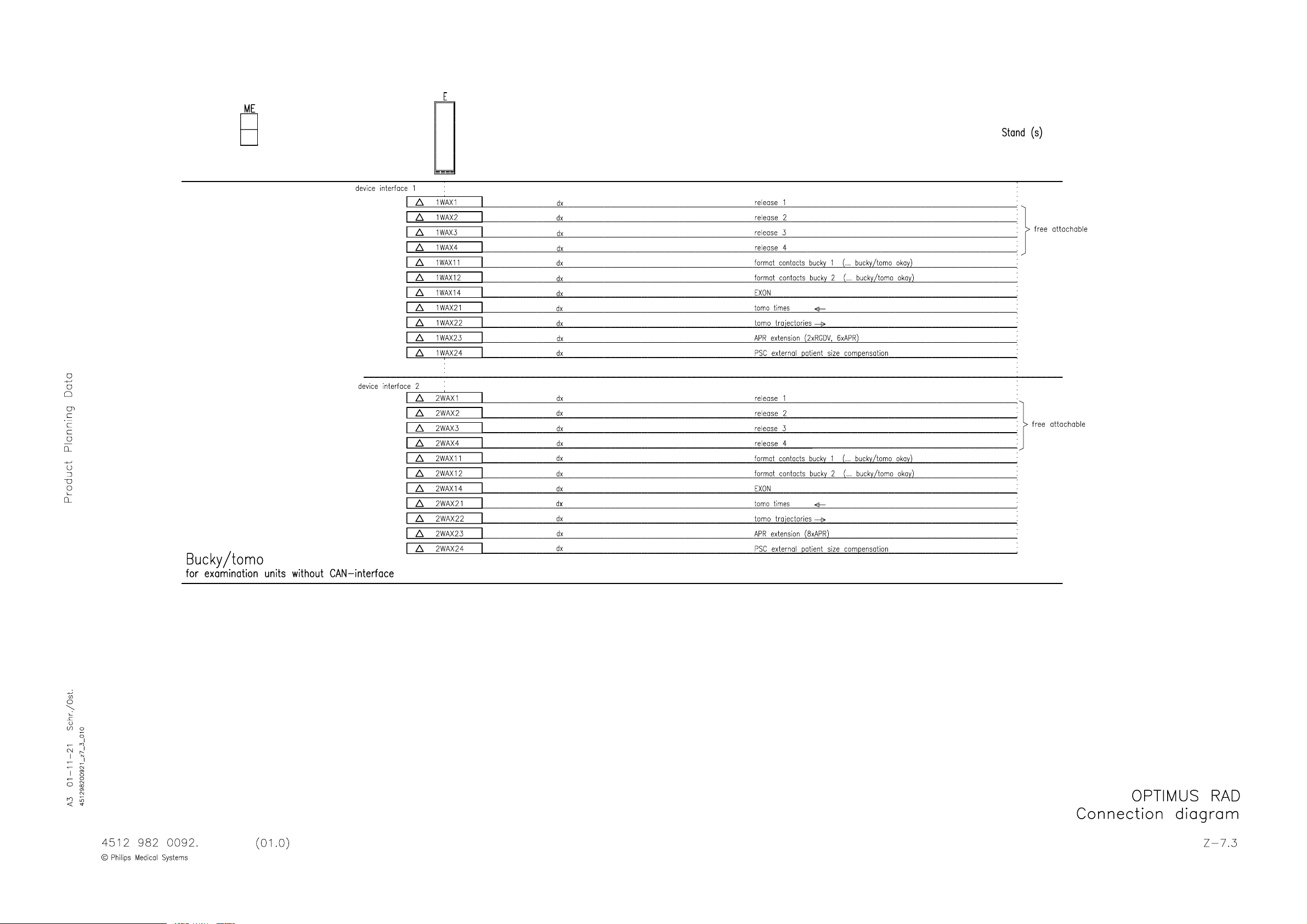
Connection diagram 1Z--7.3...................................................
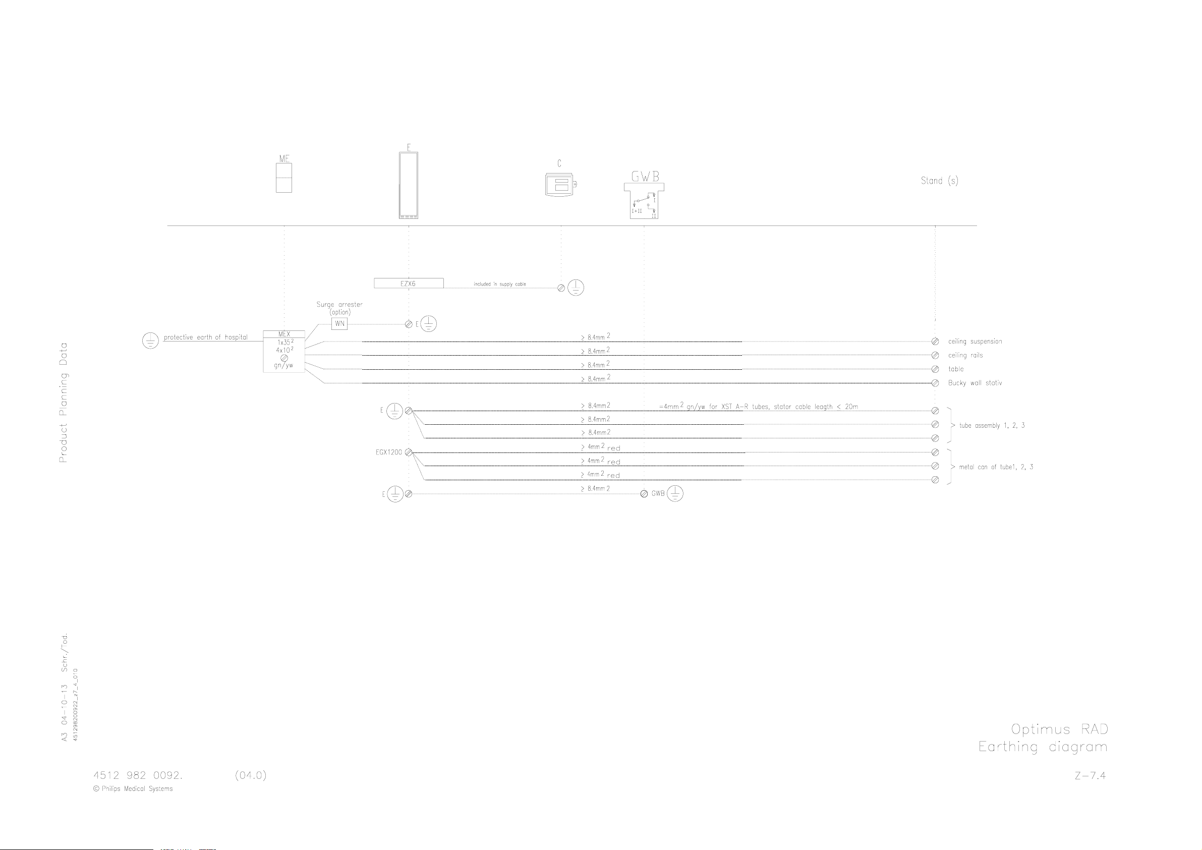
Earthing diagram 1Z--7.4......................................................
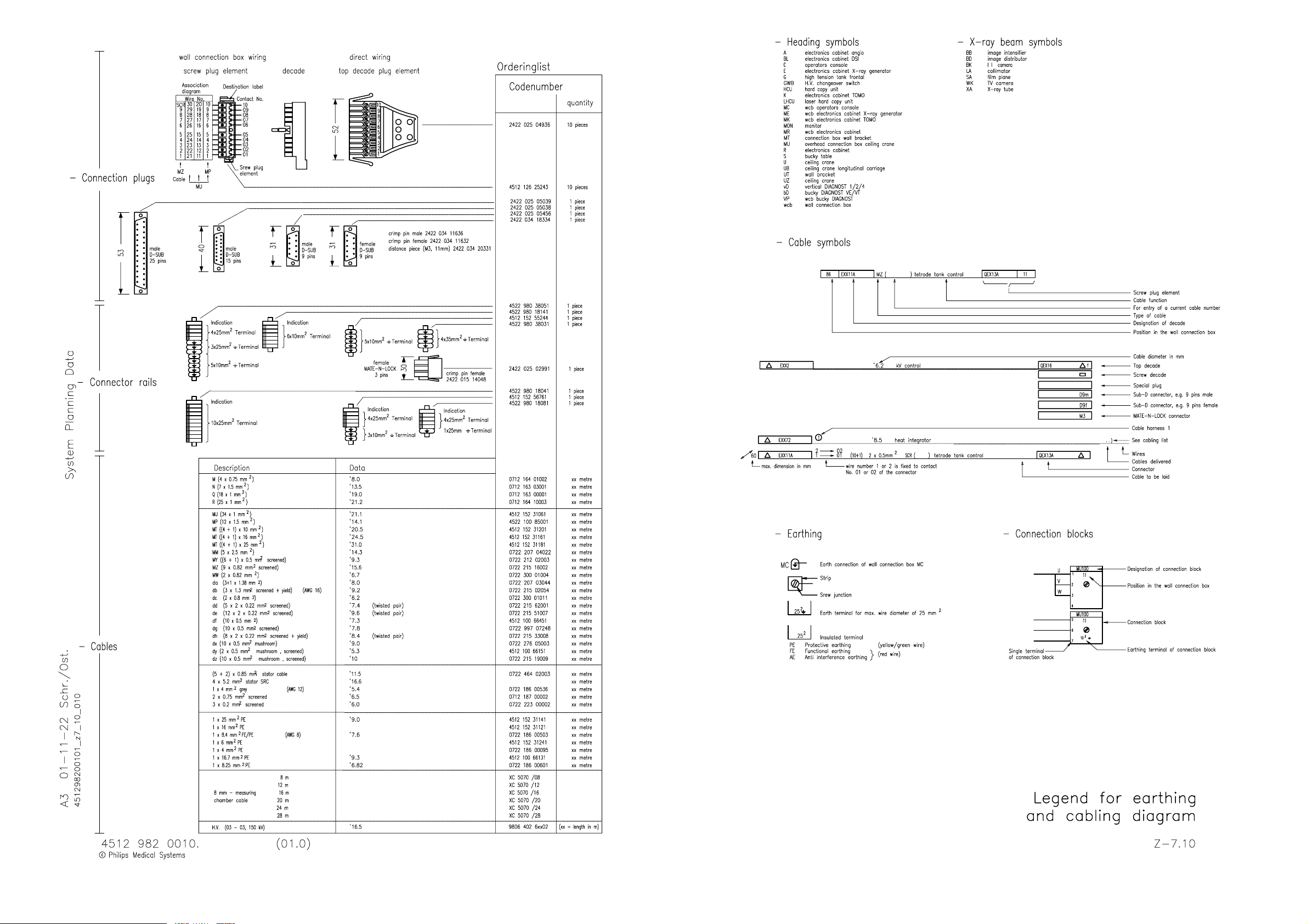
Legend for earthing and cabling diagram Z--20.1..................................
2004 Philips Medical Systems
ALL RIGHTS RESERVED
OPTIMUS RAD(e/04.0)1--0.2
OPTIMUS_RAD_1_e040_inh
Page 7

OPTIMUS RAD
INTRODUCTION AND TECHNICAL DATA
1. Product information
The Optimus family of generators for radiography is based on computer-controlled converter technology.
The converter operates in the non-audible frequency range.
Application options are essentially achieved by releasing software modules using customized PAL ICs.
Control between the internal Function Units (FUs) and the external online equipment takes place by a CAN bus.
Safety-relevant signals are transferred directly on the so-called “Signal bus”.
Units without any CAN interface are operated by the ”Adapter for 4 auxiliary units WA” option.
1.1. Applications
-- Radiography
-- Tomography
1.2. Options
Component overview according to the commercial catalogue.
Only the versions in the current commercial catalogue can be ordered.
If an existing generator is to be upgraded the commercial department must order:
MGR0011 (upgrade of an existing configuration)
+ MGRxxxx
+S/N
1.2.1. Hardware options + MGR0011 + S/N
-- Low-speed rotor control 9890 000 0220x...............................
-- Dual-speed rotor control 9890 000 0268x MGR2082.............................. ............
-- Mains transformer 400 -- 480V; 50 / 60Hz,
also for 400V mains supply without neutral lead N
with taps for 400 / 440 / 460 / 480V 9890 000 0230x.....................
-- Mains transformer 190--390V; 50 / 60Hz
with taps for 190 / 200 / 207 / 220 / 230 / 240 / 250 /
343 / 380 / 390V max. 50kW! 9803 720 8100x.......................
-- Adapter for 4 aux. units WA 9890 000 0231x MGR2131........................... ............
-- Option rack 9890 000 0232x..........................................
-- Extension set for one additional tube 9890 000 0234x...................
-- Tube extension WG 9890 000 0238x..................................
-- Operating panel 9890 000 0240x.....................................
-- Operating module Optimus 9890 000 0278x............................
-- Operating desk data cable 10m, 20m, 30m 9890 000 0241x / 2x / 3x..............
-- Stand for operating panel 9890 000 0244x MGR1482............................. ............
OPTIMUS RAD (e/04.0)
OPTIMUS_RAD_1_e040_BW
E 2004 Philips Medical Systems
ALL RIGHTS RESERVED
1--1
Page 8

OPTIMUS RADINTRODUCTION AND TECHNICAL DATA
-- Wall mounting of operating panel 9890 000 0245x.......................
-- 26VDC / 230VAC adapter 9890 000 0246x MGR2281............................. ............
-- Surge arrester WN 9890 000 0247x...................................
-- Handswitch for Optimus 9890 000 0249x...............................
-- Patient Data Organizer (PDO) 9890 000 0255x MGR2091......................... ............
-- Decade cable set 14 x 4m top decade → AMP decade 9803 704 2010x....
-- APR extension 9890 000 0257x.......................................
-- Extension photo pick-up Optimus 9890 000 0258x.......................
1.2.2. Software options + MGR0011 + S/N
Software options are provided by the function key (see also 5Z--1, EZ 139 Central Unit D38).
Additional hardware components are not required.
-- Automatic Exposure Control (AEC) 9890 000 0281x
-- Anatomically Programmed Radiography / Fluorography (APR/F) 9890 000 0282x
1)
1)
-- Automatic Tomo Time Input (TTI) 9890 000 0222x MGR2121............................ .......
-- Tomo Density Control (TDC) 9890 000 0223x MGR2122................................. .......
-- VARIOFOCUS 9890 000 0227x MGR2101............................................. .......
-- Area dose calculator 9890 000 0256x MGR2141........................................ .......
1)
= Options only for base 9890 000 0218x
Options are always included in base 9890 000 0216x
MGR2171.......................... .....
MGR2181. .....
E 2004 Philips Medical Systems
ALL RIGHTS RESERVED
OPTIMUS RAD(e/04.0)1--2
OPTIMUS_RAD_1_e040_BW
Page 9

OPTIMUS RAD
INTRODUCTION AND TECHNICAL DATA
2. Compatibility
2.1. Generator components
-- Base Optimus 9890 000 0218x...............................
-- H.V. transformer 1 tube, 50kW 9890 000 0203x...... .........
-- H.V. transformer 2 tubes, 50kW 9890 000 0204x MGR2051 (Upgrade 1 ----> 2) tubes...... ........ ....
-- H.V. transformer 1 tube, 65 / 80kW 9890 000 0205x...... ......
-- H.V. transformer 2 tubes, 65 / 80kW 9890 000 0206x MGR2052 (Upgrade 1 ----> 2) tubes...... ..... ....
-- 50kW extension -- RAD 9890 000 0262x.......................
-- 50kW extension -- RAD 480V 9890 000 0208x..................
-- 65 / 80kW extension -- RAD 9890 000 0264x...................
-- 65 / 80kW extension -- RAD 480V 9890 000 0209x..............
-- Firmware Rel. 3.6 9890 000 0251x............................
2.2. Tubes
Recommended standard tubes:
-- RO 17 50
-- SRO 25 50
-- SRO 33 100
Further compatible tubes:
-- RO 30 -- SRO 09 51 -- SRO 20 55
-- RO 12 30 -- SRO 13 30 -- SRO 22 50
-- RO 16 48 -- SRO 20 50 -- SRO 32 100
-- RO 30 50
Compatible tube housings:
-- ROT 350
-- ROT 351
The latest information on further tubes which are connectable is available at the service center Hamburg.
NOTE
When the generator is retrofitted it is important to use the screened cable 3 x 1.31mm
2
(0722 215 02054) as
the stator cable.
If necessary, exchange the old stator cable.
___________________
2.3. Five-field bucky chamber
-- Five-field bucky chamber 9890 000 7000x
The five-field bucky chamber is compatible with rel. 3.6 or higher.
OPTIMUS RAD (e/04.0)
OPTIMUS_RAD_1_e040_BW
E 2004 Philips Medical Systems
ALL RIGHTS RESERVED
1--3
Page 10

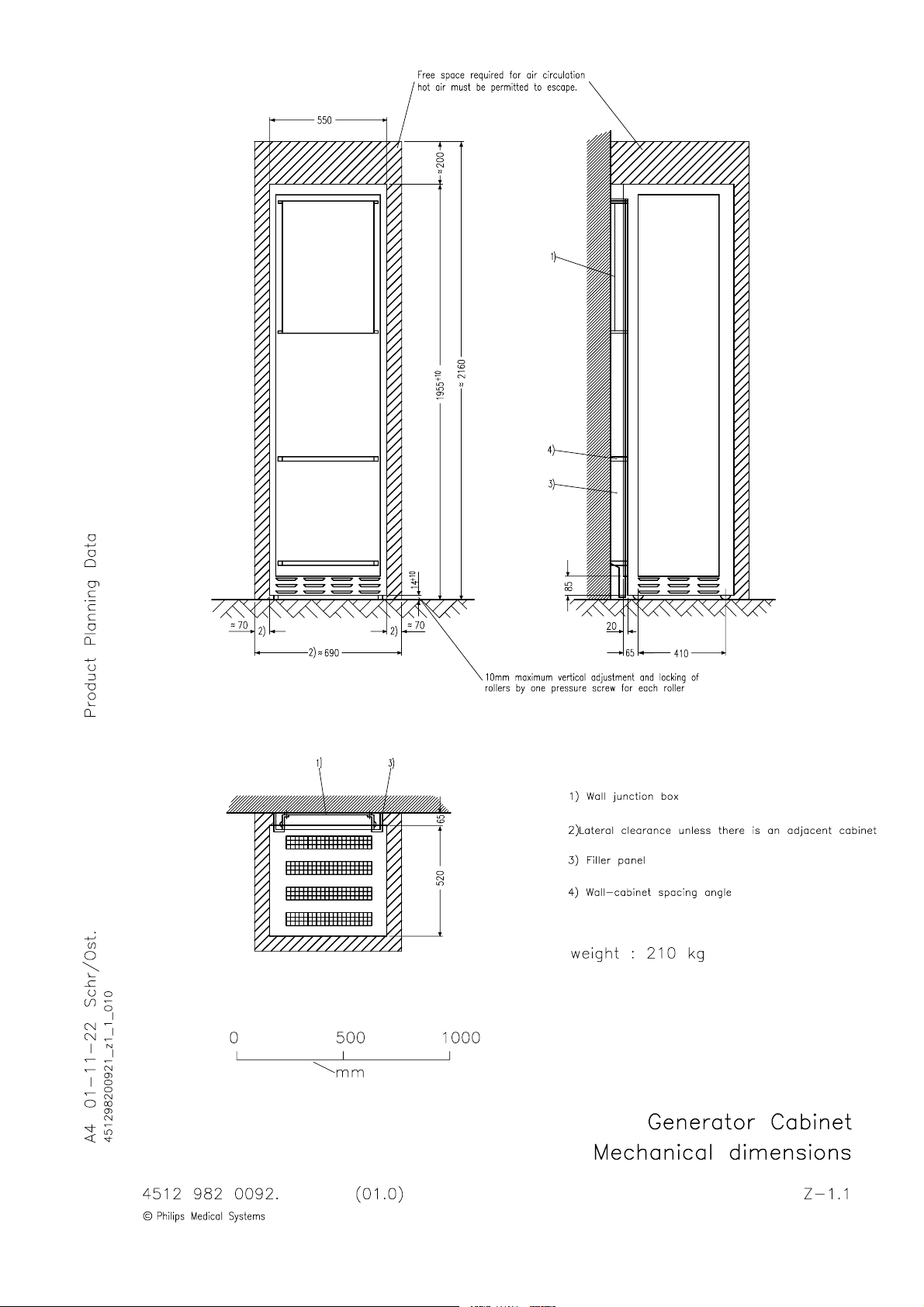
3. Mechanical data
C
For installation dimensions and weights see drawings Z--1.1.
Transport data:
Weights [kg] Dimensions [cm]
aseNo.Contents
-- Generator cabinet
1
-- Operating panel
-- Cables
net gross length width height
178 226 210 82 84
OPTIMUS RADINTRODUCTION AND TECHNICAL DATA
1--tube version:
2
Contents: H.V. generator
2--tube version:
73
88
100
77 67 80
115
4. Environmental data
The environmental data comply with PMS standard UXW 13600.
4.1. Electrical environment
Class S0 -- Dedicated mains supply, 3 phases and neutral. Thus single phase voltage is also available.
A low impedance, permanently installed connection, fed in by the step-down transformer of the hospital to supply
large systems like in MR, CT and X--ray departments is required.
NOTE
Use always a mains cable with 4 wires and concentric PE--shield, type NYCY .
___________________
4.2. Climatic conditions
Ambient temperature 10_C--40_C.............
Relative humidity 15% -- 90%; no condensation.................
Relative atmospheric pressure 70kPa -- 110kPa.....
4.3. Emission
Heat dissipation max. 500W; average per hour.....................
Noise level ≈ 46dBA.........................
EMC IEC 950...............................
To avoid any possible annoying noise of the implemented fans it is advisable to install the generator cabinet outside
the examination room.
OPTIMUS RAD(e/04.0)1--4
E 2004 Philips Medical Systems
ALL RIGHTS RESERVED
OPTIMUS_RAD_1_e040_BW
Page 11

OPTIMUS RAD
(
)
5. Electrical data
5.1. Power data and mains conditions
50kW 65kW 80kW
Mains voltage 3 x 400V ±10% (≅ 415V
3 x 400 / 440 / 460V ±10% *
6%
3 x 480V
3 x 190 ... 343V ±10% **
* = with internal mains transformer (option)
** = with external mains transformer; max. 50kW (option)
+
|
--10%
Frequency
INTRODUCTION AND TECHNICAL DATA
Voltage
+6%
/ 380V
-- 5 %
)
*
50kW 65kW 80kW
Mains frequency 49 ... 61Hz
Max. mains current
Voltage
50kW 65kW 80kW
Exposure: 400V 145A 190A 230A
440V 135A 180A 215A
460V 125A 170A 210A
480V 120A 160A 205A
190V 300A -- --
Short--time
power consumption
100kVA 132kVA 160kVA
[I x U x √3]
Fuse protection
slow-blow
35A 50A
100A at ≤ 240V --
Connected load
[I
xUx√3]
Fuse
25kVA 35kVA
Emergency
power supply:
static
(inverter)
dynamic
(diesel generator
with flywheel mass)
OPTIMUS RAD (e/04.0)
OPTIMUS_RAD_1_e040_BW
Short--time power consumption
[I x U x √3]
Connected load
[I
xUx√3]
Fuse
E 2004 Philips Medical Systems
ALL RIGHTS RESERVED
1--5
Page 12

Mains resistance
OPTIMUS RADINTRODUCTION AND TECHNICAL DATA
Voltage
50kW 65kW 80kW
400V ≤ 300mΩ ≤ 200mΩ
440V ≤ 350mΩ ≤ 240mΩ
460V ≤ 350mΩ ≤ 240mΩ
480V ≤ 400mΩ ≤ 300mΩ
480V valid for DOD only ≤ 300mΩ ≤ 240mΩ ≤ 180mΩ
NOTE
500m
Ω
is the absolute max. mains resistance.
5.2. Power supply for applications
Generator power
50kW 65kW 80kW
Max. output power 230V / 400V; max. 5A
5.3. Operating data
Generator power
Data
Tube current 1 ... 650mA 1 ... 900mA 1 ... 1100mA
Tube voltage 40 ... 150kV in kV-- or %--steps
mAs product 0.5 ... 850mAs
Exposure time 1ms ... 6s / 16s
Exposure frequency ≤ 12exp./s
Interfacing option for door contact, external radiation warning indicator
50kW 65kW 80kW
E 2004 Philips Medical Systems
ALL RIGHTS RESERVED
OPTIMUS RAD(e/04.0)1--6
OPTIMUS_RAD_1_e040_BW
Page 13
OPTIMUS RAD
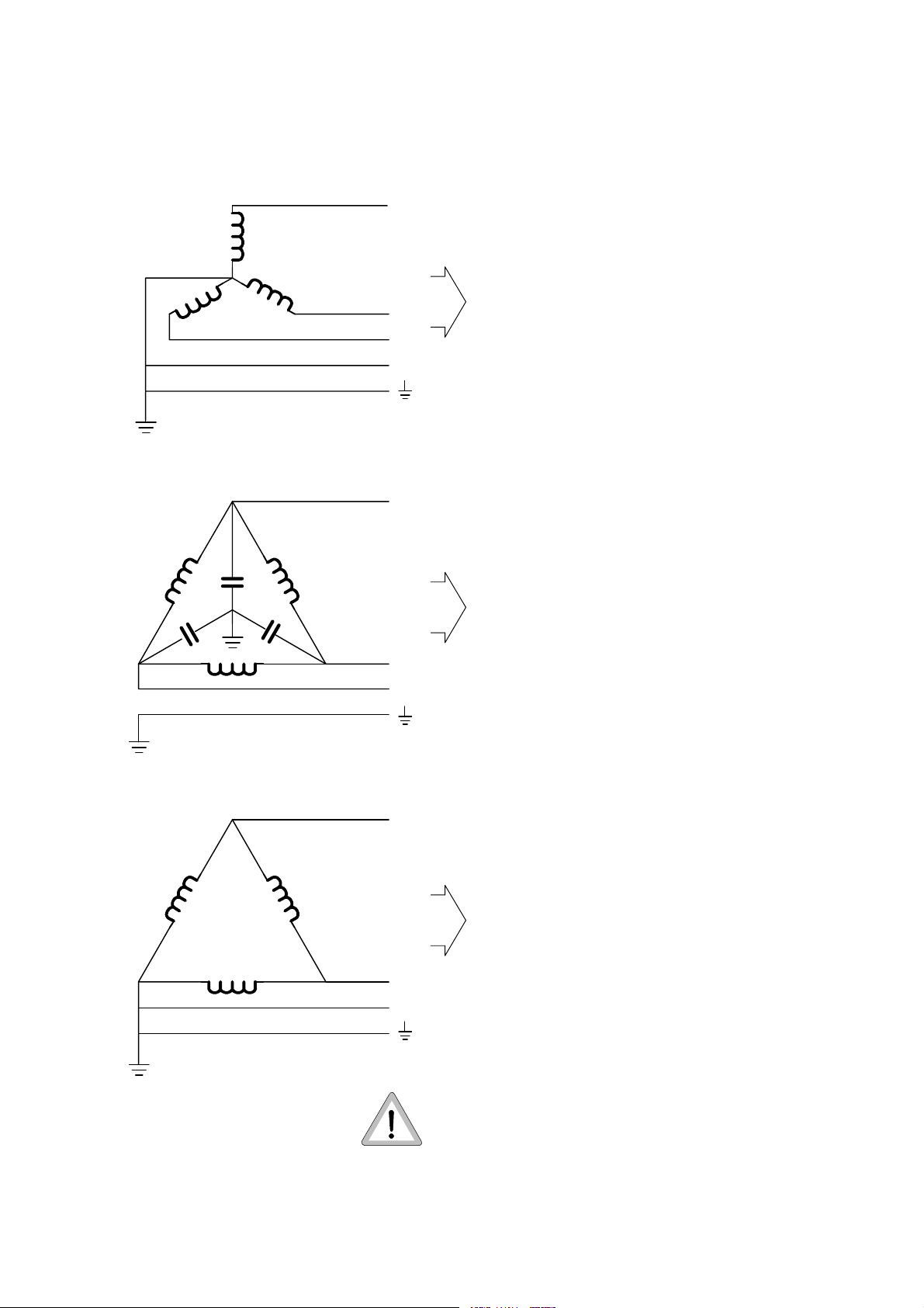
5.4. Power supply
5.4.1. Type of power supply
3-phase WYE
INTRODUCTION AND TECHNICAL DATA
L1
L2
L3
(N)
3-phase DELTA,
balanced earth or floating
L1
L2
L3
X-ray
installation
X-ray
installation
-- 400V
-- 440V / 460V / 480V
with mains transformer
9890 000 0230x.
-- Surge arrester WN is required if
the mains transformer
9890 000 0230x is ordered.
-- Neutral not required if the
mains transformer
9890 000 0230x is ordered.
-- 190V ... 343V with
external mains transformer
9803 720 8100x (max. 50kW).
-- Mains transformer
9890 000 0230x is required.
-- 400V / 440V / 460V / 480V
-- Surge arrester WN is required.
-- 190V ... 343V with
external mains transformer
9803 720 8100x (max. 50kW).
Works only together with the
internal mains transformer.
3-phase DELTA,
grounded
L1
-- Mains transformer
9890 000 0230x is required.
-- 400V / 440V / 460V / 480V
X-ray
installation
L2
L3
CAUTION
Ensure the sequence of phases in the wall junction box corresponds to designations L1, L2, L3.
___________________
-- Surge arrester WN is required
(requires modification at the
EMC--filter of the kV power
unit).
-- 190V ... 343V with
external mains transformer
9803 720 8100x (max. 50kW).
Works only together with the
internal mains transformer.
OPTIMUS RAD (e/04.0)
OPTIMUS_RAD_1_e040_BW
E 2004 Philips Medical Systems
ALL RIGHTS RESERVED
1--7
Page 14
5.4.2. Calculating the mains resistances
OPTIMUS RADINTRODUCTION AND TECHNICAL DATA
NOTE
The cross section of lead l
must not exceed 25mm2(see figure below).
3
___________________
If possible the sum of R
smaller than the R
requires.
XG
0,R1,R2
and R3should be
R
+R1+R2+R3<R
0
With higher internal mains resistances the generator
output is reduced correspondingly.
R
designates the mains resistance of the distributor transformer
0
R
depends on the length of lead l1between distributor transformer and mains distributor
1
L1
L2
L3
l
1
and on the selected cross section as well:
==> R
R
consists of upstream elements such as:
2
1=l1
× R
Cu
RCufrom table below
-- Emergency-OFF switch 4.0mΩ.................
-- Earth-leakage circuit -breaker 5.5mΩ............
l
3
XG
MEX 100
L1
L2
L3
357J94
-- Fuse 5.5mΩ.................................
-- Surge arrester WN 23.0mΩ...................
R
depends on the length of lead l3between mains distributor and wall junction box
3
and on the selected cross section as well:
==> R
3=l3
× R
Cu
RCufrom table below
The resistances consider the go and return lines so that the calculation can be based on simple cable lengths.
Copper cross section
[mm
2
]
Resistance R
[mΩ/m]
Cu
16 2.19
25 1.4
35 1.0
50 0.7
70 0.5
95 0.38
120 0.30
150 0.24
NOTE
500m
Ω
is the absolute max. mains resistance.
___________________
E 2004 Philips Medical Systems
ALL RIGHTS RESERVED
OPTIMUS RAD(e/04.0)1--8
OPTIMUS_RAD_1_e040_BW
Page 15

OPTIMUS RAD
INTRODUCTION AND TECHNICAL DATA
5.4.3. Earth-leakage circuit-breaker
To be provided between mains fuse and X-ray installation depending on local regulations.
Siemens earth-leakage circuit--breaker N 5SZ type B:
-- Order No.: 5SZ3 466 OKG00
-- Rated fault current 30mA
-- Rated current 63A
-- Connection terminals for wire cross sections of up to 25mm
2
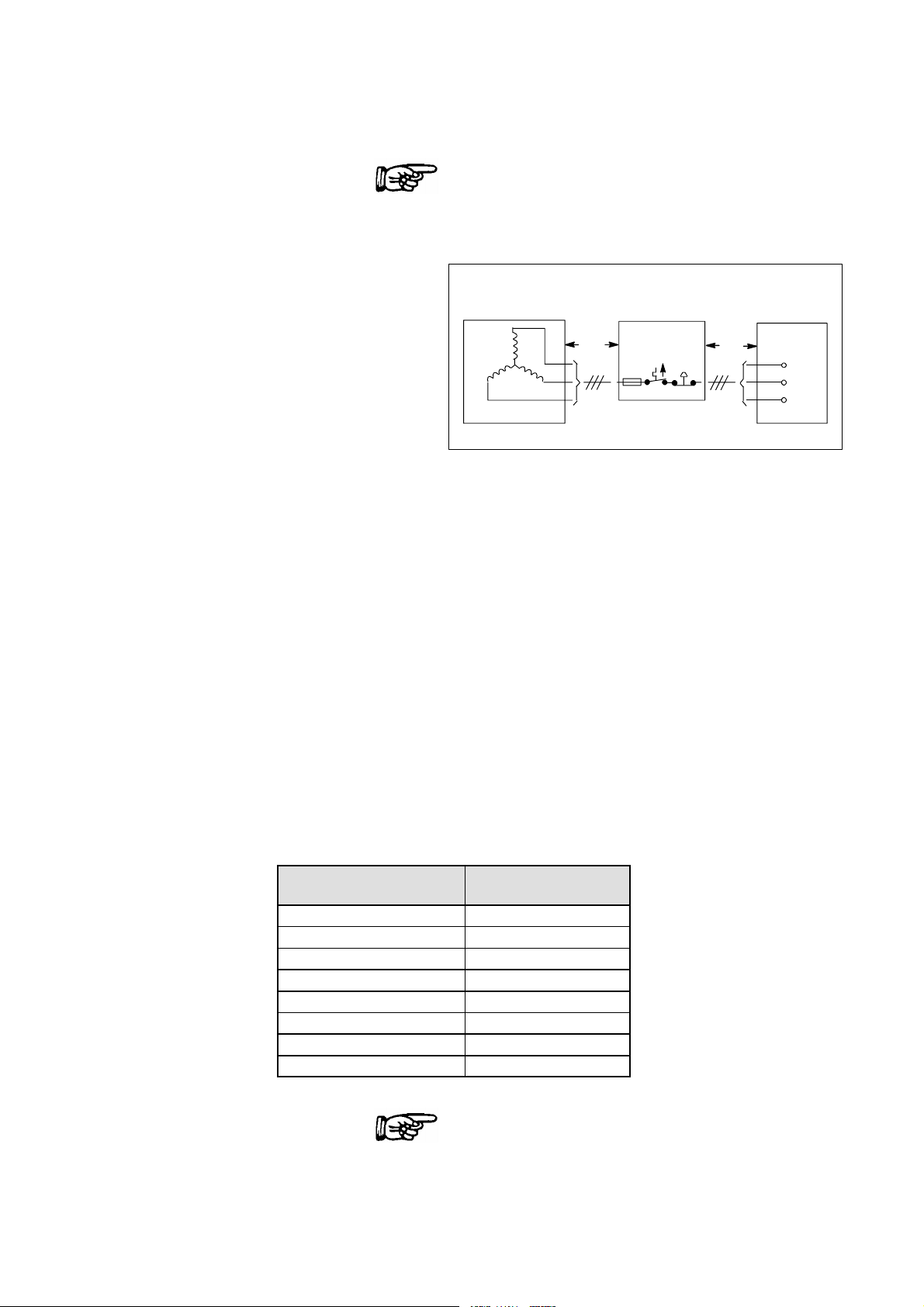
5.4.4. Emergency--OFF device
To be provided depending on local regulations.
There are 2 possibilities:
1. All the Emergency--OFF buttons are connected in series and looped into the switch--ON circuit (12VDC) of
the generator.
2. The Emergency--OFF circuit acts on an external mains contactor which switches OFF the power before it is
fed into the generator.
OPTIMUS RAD (e/04.0)
OPTIMUS_RAD_1_e040_BW
E 2004 Philips Medical Systems
ALL RIGHTS RESERVED
1--9
Page 16

OPTIMUS RADINTRODUCTION AND TECHNICAL DATA
6. Tools
-- Service engineer standard tool kit
-- Service-PC:
Zeppelin standard, Win 2000 compatible.
-- Installation and service software AGent.
-- Security device, parallel port key or smart card, PMS security.
Necessary to carry out the installation and to run the service software (special programming, fault finding).
-- 0-modem cable:
The minimum length is the distance between generator cabinet and operating desk.
Male 25-pole D-Sub connector at the generator side.
A 5m data cable of the bucky controller can be used: 4512 130 5693x
-- Mains resistance measuring instrument
-- Dose measuring instrument
-- mAs--meter
-- Multimeter
-- Digital oscilloscope with 2-beam memory
-- Recommended PLCC extraction tool (AMP 822154--1): 2422 487 89772
7. Traceable items
The following items have serial numbers of the following format when delivered ex factory:
1. Generator cabinet 6-digit serial number........
2. H.V. tank 7-digit serial number................
3. Operating desk 8-digit serial number..........
E 2004 Philips Medical Systems
ALL RIGHTS RESERVED
OPTIMUS RAD(e/04.0)1--10
OPTIMUS_RAD_1_e040_BW
Page 17

OPTIMUS RAD
INTRODUCTION AND TECHNICAL DATA
8. Preparation
Connection of the generator: see drawing Z--6.1................
Operating panel: see drawing Z--1.3..........................
Connection diagram: see drawing Z--7.1/.2/.3/.4.......................
Earthing diagram: see drawing Z--7.5.........................
Legend for earthing and cabling: see drawing Z--7.10.............
8.1. Installation material
To be ordered from the service department of PMS Hamburg:
-- Wall junction box 4512 103 7538x.............................
2
including connection block (25mm
-- Relay for radiation warning indicator 4512 100 4523x............
One interface relay with a floating contact (230V/1A) is included in the scope of delivery of the generator.
) for mains supply and connection block (10mm2) for unit supply.
8.2. Cables
H.V . cables
with O3 / O3 plugs: 9806 402 6xx02................................
length: 6m -- 30m in steps of 2m...........................................
capacity: 155pF/m.........................................
diameter: 16.5mm........................................
The cable length is indicated by the 9th and 10th digit of the numeric code.
Thermal contact cable
-- 3-wire screened for 1 excess temperature switch 4512 100 66162.............
(3 x 0.5mm2, ∅ 5.3mm)
-- 10-wire screened for additional supervision like
temperature alarm switch, buzzer, selection indicator 0722 215 19005.........
Stator cable
3×1.31mm
2
, screened 0722 215 02054.....................................
NOTE
The above described cables are part of the pre--installed systems.
___________________
OPTIMUS RAD (e/04.0)
OPTIMUS_RAD_1_e040_BW
E 2004 Philips Medical Systems
ALL RIGHTS RESERVED
1--11
Page 18

OPTIMUS RADINTRODUCTION AND TECHNICAL DATA
AMPLIMAT cable
with D-Sub and 3--Plus plug:
12m 9890 000 01721......................
16m 9890 000 01731......................
20m 9890 000 01741......................
24m 9890 000 01751......................
CAUTION
AMPLIMAT cables 9803 507 0xx02 (for hybrid measuring chambers 9803 509 xxxxx) with 3- Plus plugs
at both ends must be connected in the generator by the following adapter for each cable:
___________________
Adapter for AMPLIMAT cable: 4512 108 09042. The generator includes 1 adapter.
The hybrid measuring chambers 9803 509 xxxxx require connection (chassis) between contacts:
D--Sub end GND (13) <-- ----> RF 0V (8) (generator input)
or
3--Plus end GND (N) <-- ----> RF 0V (J) (generator input)
This connection is established by the adapter for the AMPLIMAT cable.
See drawing Z1--6 ”Basic interface”.
In case a hybrid measuring chamber 9803 509 xxxxx is not operated with the required
AMPLIMAT cable 3--Plus / 3--Plus 9803 507 0xx02... .....
but with
AMPLIMAT cable D--Sub / 3--Plus 9890 000 017xx... .....
make sure to establish this connection (13 <-- -- --> 8) in the D--Sub connector!
For ALC measuring chambers 9890 000 016xx connection GND <------> RF 0V is not permitted.
Therefore, ALC measuring chambers AMPLIMAT cables 9890 000 017xx should always be used.
Operating desk
NOTE
Use the shortest cables. Noise immunity increases.
___________________
Cable set 10m 9890 000 02411.......................
20m 9890 000 02421.......................
30m 9890 000 02431.......................
8.3. Manpower
At least two persons are necessary to insert the H.V . tank in the generator cabinet.
The weight of the 2--tube version is about 88kg.
E 2004 Philips Medical Systems
ALL RIGHTS RESERVED
OPTIMUS RAD(e/04.0)1--12
OPTIMUS_RAD_1_e040_BW
Page 19

OPTIMUS RAD
INTRODUCTION AND TECHNICAL DATA
9. Planned maintenance
The technical documentation for carrying out maintenance work in compliance with the applicable regulations are
available at the responsible authority of Philips Medical Systems.
The importance of having maintenance implemented is pointed out to the operator in the operating instructions.
It must be guaranteed that the person carrying out maintenance work knows about the respective national
regulations and that this person observes these regulations throughout all steps of maintenance work.
OPTIMUS RAD (e/04.0)
OPTIMUS_RAD_1_e040_BW
E 2004 Philips Medical Systems
ALL RIGHTS RESERVED
1--13
Page 20
Page 21
Page 22

Page 23

Page 24
Page 25
Page 26
Page 27
Page 28
Page 29
Page 30

OPTIMUS RAD
1. Installing the wall junction box 2--1........................................
1.1. Fixing of the wall junction plates to the walll junction plates 2--2..................
1.2. Use of the cable support and the fixing rail of the wall junction box 2--3...........
2. Preparatory work 2--4.....................................................
2.1. Mounting of the H.V. generator in the cabinet 2--4..............................
2.2. Electrical connection of the H.V. generator 2--5................................
3. Installing the operating panel 2--7.........................................
3.1. Desk version 2--7..........................................................
3.2. Stand version 2--9.........................................................
3.3. Wall mounted version 2--10..................................................
3.4. Supporting angle version 2--11...............................................
3.5. Additional release switch 2--11...............................................
4. Electrical connection 2--12.................................................
4.1. Earthing 2--12..............................................................
4.2. Mains connection 2--12......................................................
4.2.1. Mains connection of the generator 2--12.......................................
4.3. Stator connection 2--13......................................................
4.3.1. Shielding 2--13.............................................................
4.3.2. Connection 2--14...........................................................
4.4. Signal cables 2--17.........................................................
4.4.1. Room decade cable 2--17....................................................
4.4.2. Tube supervision 2--18......................................................
4.4.3. CAN interface 2--19.........................................................
4.4.4. Adapter for four auxiliary units 2--20...........................................
4.4.5. Dose inputs 2--21...........................................................
4.4.6. Patient data organizer PDO (option) 2--21......................................
4.5. H.V . cables generator side 2--22..............................................
4.6. Emergency--OFF circuit 2--22................................................
5. Hardware programming 2--23...............................................
5.1. Mains transformer (option) 2--23..............................................
5.2. PCB EZ150 basic interface 2--24.............................................
6. Switch-ON of the generator 2--25...........................................
7. Installation software AGenT 2--26...........................................
7.1. PC and generator settings to avoid problems during up/downloading
7.1.1. Preparation of the service PC to guarantee a safe loading process 2--26...........
7.1.2. Preparation of the generator 2--27............................................
7.2. Interface 2--28.............................................................
8. Setting-to-work overview 2--30.............................................
8.1. Configuration 2--31.........................................................
8.1.1. Date and time 2--31.........................................................
8.1.2. Mains data 2--31...........................................................
8.1.3. Tubes 2--32................................................................
8.1.3.1. Tube data set 2--33.........................................................
8.1.3.2. Tube speed selection 2--34..................................................
INSTALLATION
INSTALLATION
Contents
TEXT
Contents 2--0.1............................................................
of CU complete files 2--26...................................................
OPTIMUS RAD (d/04.1)
OPTIMUS_RAD_2_d041_inh
2004 Philips Medical Systems
ALL RIGHTS RESERVED
2--0.1
Page 31

OPTIMUS RADINSTALLATION
8.1.3.3. Tube limits 2--34............................................................
8.1.3.4. Capacitance of tube connection 2--35.........................................
8.1.3.5. Tube operating modes 2--36.................................................
8.1.3.6. Disable tube 2--36..........................................................
8.2. Registration devices 2--37...................................................
8.2.1. Data set A ... B 2--37........................................................
8.2.2. Interface assignment 2--41...................................................
8.2.3. Examples for RGDV programming 2--43.......................................
8.3. Tube adjustment 2--44......................................................
8.3.1. Tube conditioning 2--44......................................................
8.3.1.1. Preconditions / Program settings 2--44........................................
8.3.1.2. Procedure 2--45............................................................
8.3.2. Tube adaptation 2--49.......................................................
8.3.2.1. General information 2--49....................................................
8.3.2.2. Preconditions / Program settings 2--50........................................
8.3.2.3. Procedure 2--51............................................................
8.3.3. Final tube adjustment work 2--52.............................................
8.3.4. Problems during adaptation -- Symptoms and solutions 2--53.....................
8.4. Dose rate control 2--54......................................................
8.4.1. Amplimat sensitivity 2--54....................................................
8.4.2. Screen/film combinations 2--54...............................................
8.4.2.1. Automatic DRC processing 2--55.............................................
8.4.2.2. Manual DRC processing 2--56................................................
8.4.2.3. Density correction for AEC technique (option) 2--57.............................
8.4.3. Faulty exposure detection 2--58..............................................
8.5. Application limits 2--59......................................................
8.5.1. X-mode limits 2--59.........................................................
8.5.2. Thoravision limits 2--60......................................................
8.6. Human interface 2--61.......................................................
8.6.1. Language 2--62............................................................
8.7 Option: Tomo density control TDC 2--62.......................................
8.8. Option: Area dose calculator 2--63............................................
8.9. Acceptance test 2--63.......................................................
8.10. Interlock facility for APR modification 2--64.....................................
8.11. Backup of all configuration data 2--64.........................................
9. Labels 2--65...............................................................
10. Final installation work 2--66................................................
DRAWINGS
RGDV programming (3x) 2Z--2.0......................................................
RGDV programming example: 2 2Z--2.2................................................
RGDV programming example: 4 2Z--2.4................................................
RGDV programming example: 5 2Z--2.5................................................
RGDV programming example: 6 2Z--2.6................................................
RGDV programming example: 8 2Z--2.8................................................
RGDV programming example: 9 2Z--2.9................................................
RGDV programming example: 10 2Z--2.10..............................................
List of characters 2Z--3..............................................................
Data sets of chambers 2Z--4.........................................................
Programming of device interfaces 2Z--5................................................
Labeling 2Z--10.....................................................................
OPTIMUS RAD(d/04.1)2--0.2
2004 Philips Medical Systems
ALL RIGHTS RESERVED
OPTIMUS_RAD_2_d041_inh
Page 32

OPTIMUS RAD
INSTALLATION
1. Installing the wall junction box
S Mount the wall junction box at the place where the generator is intended to be installed
(see drawing “Connection of generator” in section 1 and manual UNIT 4512 103 75380 for wall junction boxes).
S If necessary, install the optional surge arrester WN inside the wall junction box
(see surge arrester documentation.)
S If applicable, mount the wall junction plates of the generator to the wall junction box.
S Have the mains cable present at the clinic connected to mains terminal MEX by a person who is authorized for
this job.
S Check the phase sequence of L1, L2 and L3.
WARNING
Switch OFF the mains supply present at the clinic and make sure that it cannot be switched ON again
accidentally
.
___________________
CAUTION
The wall junction plates must in any case be installed at the wall junction box and not at the generator.
They do not belong to the wall junction box but belong to the set of wall junction plates (4512 102 48582).
___________________
OPTIMUS RAD (d/04.1)
OPTIMUS_RAD_2_d041_BW
E 2004 Philips Medical Systems
ALL RIGHTS RESERVED
2--1
Page 33

1.1. Fixing of the wall junction plates to the wall junction box
Wall junction box centered
behind the generator cabinet E
1880
OPTIMUS RADINSTALLATION
1290
662
166
Wall junction plates
1)
1)
1) Space with no other cabinets beside thern.
E 2004 Philips Medical Systems
ALL RIGHTS RESERVED
OPTIMUS RAD(d/04.1)2--2
OPTIMUS_RAD_2_d041_BW
Page 34

OPTIMUS RAD
INSTALLATION
1.2. Use of the cable support and the fixing rail of the wall junction box
CAUTION
The wall junction plates must in any case be installed at the wall junction box and not at the generator.
They do not belong to the wall junction box but belong to the set of wall junction plates (4512 102 48582).
___________________
Cable support of wall junction box
to fix the wall junction plates
Cables going to the wall junction box
Fixing of the cables
with tie-wraps at the
cable support of the
wall junction box
Right-hand side
wall junction plate
Cover cap for cable passage
OPTIMUS RAD (d/04.1)
OPTIMUS_RAD_2_d041_BW
E 2004 Philips Medical Systems
ALL RIGHTS RESERVED
Left-hand side
wall junction plate
Fixing rail of wall junction box
to fasten the wall junction plates
2--3
Page 35

2. Preparatory work
2.1. Mounting of the H.V. generator in the cabinet
CAUTION
Do not tilt the H.V. generator while transporting it.
OPTIMUS RADINSTALLATION
In case of a tilting angle larger than 45
_
, the setting-to-work of the generator can be started not before a
waiting time of about eight hours has passed.
Otherwise the H.V. generator may be destroyed by electrical sparkover.
___________________
S Unpack generator cabinet E.
S In case the packing material of
H.V . transformer EG is strongly soiled with oil,
Deaerating hole
check whether there is any physical damage.
Check the oil level. If the oil level is too low, refill
some oil.
Tolerance: 2mm
24mm at 20 - 30_C
22mm at 30 - 36_C
Oil: Shell Diala G in 2.5l container
4512 148 43172
S Remove the deaerating screw completely from the cover of the H.V. generator. Only this way the precision of
the high voltage measuring divider corresponds to the specification.
In case of return shipment of the H.V. generator this screw must be fixed again. Therefore, keep the screw laying
on top of the cover.
CAUTION
Make sure that no foreign matter falls into the oil. Otherwise the transformer must be exchanged.
___________________
S Take the two transport bars from the rear side of the cabinet.
S Lift the H.V. generator into the generator cabinet with the transport bars.
The four connecting bolts GX1001 to 1004 must point at the front of the generator cabinet.
E 2004 Philips Medical Systems
ALL RIGHTS RESERVED
OPTIMUS RAD(d/04.1)2--4
OPTIMUS_RAD_2_d041_BW
Page 36

OPTIMUS RAD
Generator
R
k
Routethecablesalongthefrontandlef
t
Seedrawingp
age2--4
thereasonofkVsymmetry
NOT
E
k
W
Seedrawingp
age2--4
2.2. Electrical connection of the H.V. generator
S Connect the H.V. generator electrically:
INSTALLATION
Generator
version
50/65/80kW
50kW
Connection
emar
from <------> to
E1 (GND) <------> GX1100 (GND) Ground
ZX12 <------> G100X15
ZX35 <------> G100X14
Route the cables alongthe front and lefthand edge of the H.V. generator. Fix them.
Twist the cables!
QC13:1 <------> GX1003
The sequence of the connecting bolts is
Push the screening cap forward over the
QC03:1 <------> GX1002
connecting bolts and tighten it. Attach the
converter cables including the screening to
the screening cap with cable ties.
The 50kW version might have direct links
GX1001 <------> GX1003
on each side or a link on one side and a
choke of 1 ... 6 loops on the other side for
NOTE
not in numerical order.
.
.
GX1004 <------> GX1002
QC13:1 <------> GX1001
QC03:1 <------> GX1002
65/80
2QC13:1 <------> GX1003
2QC03:1 <------> GX1004
WGX61 <------> GK1:1
50/65/80kW WGX67 <------> GK1:2
2ndtube
WGX62 <------> GK2:1
WGX68 <------> GK2:2
NOTE
Do not change these links or chokes.
Twist the cables!
The sequence of the connecting bolts is
not in numerical order.
.
Push the screening cap forward over the
connecting bolts and tighten it.Attach the
converter cables including the screening to
the screening cap with cable ties.
OPTIMUS RAD (d/04.1)
OPTIMUS_RAD_2_d041_BW
E 2004 Philips Medical Systems
ALL RIGHTS RESERVED
2--5
Page 37

OPTIMUS RADINSTALLATION
S Turn the two earthing angles of the H.V. generator outward and screw them on to the members of the cabinet.
Converter cables (twisted)
fixed at the screening
cap
Earthing angles
Connection of
50kW version
Screening cap
Terminal for the
screen
of the filament
cable
Fixing signal
cable
199H96
Connection of
65/80kW version
Twist the cable
Link or choke
X1001
QC13:1
QC 03:1
X1002X1003 X1004
Link or choke
Twist the cables
QC13:1
QC03:1
X1001 X1003
X1002
2QC13:1
2QC03:1
X1004
E 2004 Philips Medical Systems
ALL RIGHTS RESERVED
OPTIMUS RAD(d/04.1)2--6
OPTIMUS_RAD_2_d041_BW
Page 38

OPTIMUS RAD
3. Installing the operating panel
3.1. Desk version
See ”Operating panel” in section 1.
Accessories:
-- 2 feet for the unit
-- 2 elastic buffers, black
-- 5 insert strips for the RGDV buttons
-- sheet with RGDV symbols
-- release switch
S Unpack the desk carefully.
S Mount the release switch on the left-hand or
right-hand side of the desk:
INSTALLATION
C300 X3
2
1
Mount the holding bracket to the edge of the
desk (1) with the two M4x10 countersunk screws.
For visual reasons the release button should be in
line with the +/-- buttons on the control desk. Use
the appropriate holes in the bracket.
Slide the release switch onto the bracket.
Fasten it parallel to the desk edge with the two
M4x10 cheese-head screws, securing rings and
washers (2).
S Screw in the two feet for the unit at the bottom of
the desk.
S Glue the two black elastic buffers to the front
edges of the bottom of the desk such that they are
acting as the front feet.
2x
OPTIMUS RAD (d/04.1)
OPTIMUS_RAD_2_d041_BW
E 2004 Philips Medical Systems
ALL RIGHTS RESERVED
2--7
Page 39

S Define the assignment of the RGDV
buttons 1 ... 8. Glue the respective symbols to
the insert strips which are provided with subsidiary
lines (1).
S Raise the keyboard about 3mm above the desk.
UseanAllenkey(2).
S Push the insert strips under the keyboard foil.
Press the angulated, protruding end of each insert
strip into the housing of the desk (3).
S Lower the keyboard to its initial position (4).
S Remove the cable cover at the rear side of the
desk.
S Connect the cables:
OPTIMUS RADINSTALLATION
1
3
3mm
2
Supply cable EZX20 <------> C200X1
EZX6 <------> earth
Data cable EZX46 <------> C300X1
Release switch <------> C300X3
Patient Data Organizer <------> C300X2 (option)
S Check the function programming plug for X44 as shown in Z2--5.2 and put it into socket EZX44.
S Provide drag relief for the supply and data cables with the clamp present on the desk.
S Screw on the cable cover.
Make sure that the cable drag relief device of the release switch (1 cable tie) remains under the cover.
4
E 2004 Philips Medical Systems
ALL RIGHTS RESERVED
OPTIMUS RAD(d/04.1)2--8
OPTIMUS_RAD_2_d041_BW
Page 40

OPTIMUS RAD
3.2. Stand version
See ”Operating panel” in section 1.
Additional accessories:
-- 4 dowels S10
-- 4 hexagon cap screws 8 x 60mm
-- 4 washers
S Position the desk stand according to the respective room layout.
S Mark the fixing holes on the floor.
S Set the four dowels supplied into the floor (drill bit: 10mm).
S Screw on the desk stand with four screws and washers.
S Route the supply and data cables from the bottom to the top within the desk stand.
Provide the cables with drag relief.
Cable ends including plugs should protrude beyond the edge of the desk by about 500mm.
INSTALLATION
S Mount the release switch as described in chapter 3.1.
S Assign the RGDV buttons 1 ... 8 to the desired symbols as described in chapter 3.1.
S Connect the cables to the desk as described in chapter 3.1.
S Screw on the cable cover.
Ensure the cable drag relief device of the release switch (1 cable tie) remains under the cover.
S Mount the operating panel on the stand.
OPTIMUS RAD (d/04.1)
OPTIMUS_RAD_2_d041_BW
E 2004 Philips Medical Systems
ALL RIGHTS RESERVED
2--9
Page 41

3.3. Wall mounted version
See ”Operating panel” in section 1.
Additional accessories:
-- 4 ball-head bolts
-- 4 dowels S8
-- 4 hexagon cap screws 5 x 30mm
-- 4 washers
-- 2 screws 4 x 10mm
-- 2 angle plates
-- 4 nuts
OPTIMUS RADINSTALLATION
S Screw on the angle plates into the wall frame.
The short ends of the angles must point upwards.
S Screw the four ball-head bolts into the wall
support.
S Mark the four fixing holes of the wall frame at the
respective place on the wall.
S Set the dowels supplied into the wall
(drill bit: 8mm).
S Screw on the wall frame with thefour hexagon cap
screws and washers.
S Provide drag relief for the supply and data cables
in the wall frame.
Cable ends including plugs should protrude
Wall fastening (4x) Ball--head bolt (4x)
Cable passage
beyond the edge of the desk by about 500mm.
S Mount the release switch as described in chapter 3.1.
S Assign the symbols to the desired RGDV buttons 1 ... 8 as described in chapter 3.1.
S Connect the cables to the desk as described in chapter 3.1.
Desk fastening
(2x)
S Mount the operating panel on the wall frame and fix it with the left two screws.
S Screw on the cable cover.
Ensure the cable drag relief device of the release switch (1 cable tie) remains under the cover.
The wall frame is designed symmetrically.
In case connection cables come from above, the frame can be mounted upside down.
Only the ball-head bolts and the angle plates still keep their position.
E 2004 Philips Medical Systems
ALL RIGHTS RESERVED
OPTIMUS RAD(d/04.1)2--10
OPTIMUS_RAD_2_d041_BW
Page 42

OPTIMUS RAD
3.4. Supporting angle version
INSTALLATION
S Screw the ball-head bolts (2) into the supporting
angles (1):
3
Left angle ------> on the left at the bottom
Right angle ------> on the right at the bottom
S Press the ball-head bolts (2) into the respective
snap bushing of the desk (4).
S Fix the supporting angles (2) to the desk (4) with
thetwoscrewsM4(3).
2
1
4
3.5. Additional release switch
An optional second release switch is supplied with a longer spiral cable: 9890 000 0249x
The scope of delivery includes various wall hooks and an adapter cable. Electrical connection shall be made in
parallel with the existing release switch which is mounted on the desk itself.
S Plug the pins of the adapter cable into the D-Sub connector of the existing release switch.
Sequence:
Adapter:
connector pin
<------>
D-Sub:
connector pin
1 <------> 6
2 <------> 9
3 <------> 7
Reference: Figure below and drawing Z1--11.1 “Operating panel C” in section Z1 “Schematic drawings”.
OPTIMUS RAD + R / F
Handswitch
9890 000 0294x
30---- / UI---- / ----24V HS
S1
89
15
S2
11 1 2
31---- /HSEXRQ
32---- /HSPRRQ
9890 000 0249x
br
1
bl
2
blk
3
Handswitch
with adapter
1
2
3
Cable adapter
4512 104 38231
br
bl
blk
Operating panel C
C 300 X 3
1
6
6
7
9
2
7
3
8
4
9
5
EXP PREP
36
OPTIMUS RAD (d/04.1)
OPTIMUS_RAD_2_d041_BW
E 2004 Philips Medical Systems
ALL RIGHTS RESERVED
2--11
Page 43

OPTIMUS RADINSTALLATION
Mai
4. Electrical connection
4.1. Earthing
See ”Earthing diagram” in section 1.
4.2. Mains con n ectio n
4.2.1. Mains connection of the generator
WARNING
Switch OFF the mains supply present at the clinic and make sure that it cannot be switched ON again
accidentally
___________________
.
See ”Connection diagram” in section 1.
S Measure the internal mains resistance at the terminal MEX with a suitable measuring instrument.
L1 - L2: R
L1 - L3: R
L2 - L3: R
= ............... mΩ
i
= ............... mΩ
i
= ............... mΩ
i
Required max. mains resistance at generator input:
Mains resistance
ns voltage
30kW 50kW 65/80kW
190V * -- 40mΩ -220V * 130mΩ 60mΩ --
240V * 160mΩ 80mΩ --
380V 500mΩ 300mΩ 200mΩ
400V 500mΩ 300mΩ 200mΩ
440V 500mΩ 350mΩ 240mΩ
460V 500mΩ 350mΩ 240mΩ
480V 500mΩ 400mΩ 300mΩ
* with external mains transformer (max 50kW)
Maximum permissible internal mains resistance: 500mΩ
OPTIMUS RAD(d/04.1)2--12
E 2004 Philips Medical Systems
ALL RIGHTS RESERVED
OPTIMUS_RAD_2_d041_BW
Page 44

OPTIMUS RAD
INSTALLATION
CAUTION
Connect phase wires in correct phase sequence.
___________________
S Connect the mains cable of the generator to terminal MEX: L1 / L2 / L3 in the wall connection box.
If the optional surge arrester WN is fitted, connect the cables at that point to terminal WNX1100.
S Connect the examination unit supply (max. 5A) to terminal MEX: T1 / T2 / T3.
4.3. Stator connection
4.3.1. Shielding
CAUTION
To suppress interferences of the high-speed rotor control, the stator connections must be provided with a 360
screen at the tube and generator end.
___________________
General remarks:
S Always use screened cables: 0722 215 02054.
S Shorten the stator cable to the required length.
Do not accommodate excess lengths at the
generator.
S Keep the stator cable separate from all the other
signal cables to avoid interference.
S Earth the screen at both cable ends.
Screening procedure:
S Remove any enamel or dirt from the clamp
providing drag relief in the tube housing to make
Wire must be discarded
sure the clamp is conductive.
S Remove the plastic covering around the clamp,
about 1cm (0.5”).
Copper foil layers up to
the insulation diameter
S Wrap copper foil around the visible screen of the
cable until the original diameter of the cable is
obtained.
ROT 350 fixing clamp
S Remove the present red wire going from the
screen end to the earthing point of the tube
housing.
_
S Fix the screen of the stator cable with the clamp.
Ensure that the clamp is secured and the ground
contact works!
OPTIMUS RAD (d/04.1)
OPTIMUS_RAD_2_d041_BW
E 2004 Philips Medical Systems
ALL RIGHTS RESERVED
Screening of the stator cable
2--13
Page 45

4.3.2. Connection
Do not mix up the phases, otherwise components of the rotor control may be destroyed.
OPTIMUS RADINSTALLATION
CAUTION
___________________
At the tube
end
S Place the jumpers across terminals 100 and 200
according to the figure.
S Connect the stator cable:
wire 1 ------> phase U
wire 2 ------> phase V
wire 3 ------> phase W
101 202
U
SRO/RO
V
W
109 210
S Earth the screening of the stator cable at the tube housing with the metallic clamp.
E 2004 Philips Medical Systems
ALL RIGHTS RESERVED
OPTIMUS RAD(d/04.1)2--14
OPTIMUS_RAD_2_d041_BW
Page 46

OPTIMUS RAD
INSTALLATION
At the generator end: One -tube
See ”Connection diagram” in section 1.
S Connect the stator cable to the terminal EX1100
(U-V-W).
S Check the stator connection by measuring the
resistances:
U -- V = wire 1 -- 2 ≈ 11Ω
U -- W = wire 1 -- 3 ≈ 20Ω
V -- W = wire 2 -- 3 ≈ 9Ω
S If an inductance meter is available, measure the
following inductance values:
U -- V = wire 1 -- 2 = 57mH ±10%
V -- W = wire 2 -- 3 = 34mH ±10%
S Fix the screen below the screening clamp.
S Relieve the tension of the stator cable by a cable
tie.
version
E
U
1
Rotor control
X1100
VW
2
3
Cable tie
Screening
clamp
Tube
At the generator end: Two-tube
See ”Connection diagram” in section 1.
S Connect the stator cables to the terminals
EWG:K11/K12.
S Check the stator connections of both tubes by
measuring the resistances:
U -- V = wire 1 -- 2 ≈ 11Ω
U -- W = wire 1 -- 3 ≈ 20Ω
V -- W = wire 2 -- 3 ≈ 9Ω
S If an inductance meter is available, measure the
following inductance values:2
U -- V = wire 1 -- 2 = 57mH ±10%
V -- W = wire 2 -- 3 = 34mH ±10%
S Fix the screen below the screening clamp.
S Relieve the tension of the stator cables by cable
ties.
version
E
Screening clamps
WG
K11
642
2
1
3
1
2
Tube 1 Tube 2
K12
64
3
2
Cable ties
OPTIMUS RAD (d/04.1)
OPTIMUS_RAD_2_d041_BW
E 2004 Philips Medical Systems
ALL RIGHTS RESERVED
2--15
Page 47

At the generator end: Three-tube version
See ”Connection diagram” in section 1.
OPTIMUS RADINSTALLATION
S Connect the stator cables to the terminals
E1WG:K12 and E2WG:K11/K12.
S Check the stator connections of all 3 tubes by
measuring the resistances:
U -- V = wire 1 -- 2 ≈ 11Ω
U -- W = wire 1 -- 3 ≈ 20Ω
V -- W = wire 2 -- 3 ≈ 9Ω
S If an inductance meter is available, measure the
following inductance values:
U -- V = wire 1 -- 2 = 57mH ±10%
V -- W = wire 2 -- 3 = 34mH ±10%
S Fix the screens below the screening clamps.
S Relieve the tension of the stator cables by cable
ties.
E
K11
1WG
2
1
2
Tube 2
K12
64
3
Screening clamps
Cable ties
2WG
K11 K12
64
2
1
2
Tube 1 Tube 3
2
3
1
64
3
2
E 2004 Philips Medical Systems
ALL RIGHTS RESERVED
OPTIMUS RAD(d/04.1)2--16
OPTIMUS_RAD_2_d041_BW
Page 48

OPTIMUS RAD
4.4. Signal cables
See: -- ”Connection diagram” in section 1.
-- Z1--6 ”Basic interface” in section “Schematic drawings”
4.4.1. Room decade cable
INSTALLATION
S Connect the door switches at the generator:
EZX1: 8<------> switch <------> 10
In case no switch is present
l i n k : p in 8 < -- -- -- > p i n 10
EZ150 K1:
max. switching and loading current = 1A
max. load = 60VA AC
= 30W DC
EZX1
SW UN EX
PO26V
CMSW
RM DR CT
RM DR 0V
Door switch connection
or
10
EWGX2
EWGX3
4
5
6
8
9
room 1
room 2
1WGX3room 2
or
2WGX2room 1
2WGX3room 3
Wall junction box
--
+
Screen
ME
Umax.=230V
Imax.=1A
Radiation
indication
Door switches
CAUTION
Make sure the polarity of the relay is correct.
___________________
OPTIMUS RAD (d/04.1)
OPTIMUS_RAD_2_d041_BW
E 2004 Philips Medical Systems
ALL RIGHTS RESERVED
2--17
Page 49

S Incase tube2or3islocatedinroom2or3orwhile
room decades
Door switches
room 1
OPTIMUS RADINSTALLATION
Door switches
room 2
-- W G X 3 o r
-- 1 W G X 3 o r
-- 2 W G X 3
are intended to be used for room supervision, the
soldering link WG W1 must be placed.
Only when this link is placed it is guaranteed that
X11
1
4
2
5
3
6
Soldering link
W1
X13
1
2
X1 X2
1
2
3
4
5
6
7
8
9
10
1
2
3
4
5
6
7
8
9
10
X3
1
2
3
4
5
6
7
8
9
10
relay WG K3 pulls up and room decade WG X3 is
activated when switch-over of the tube takes
EWG
place.
See Z1--14.xx ”Tube extension”.
S If needed connect an external relay for each examination room to control external radiation warning devices.
One relay inclusive cable is part of delivery. Additional ones can be ordered: 4512 100 4523.
A mounting place is reserved on the mains connection terminal MEX of the wall junction box.
CAUTION
Make sure the polarity of the relay is correct.
___________________
4.4.2. Tube supervision
S Connect the thermal switch or the thermal sensor
of the tube housing assembly.
For U.S.A. and U.K. only:
S Connect the HHS-lamp to indicate the selected
tube housing assembly.
EZX3
PO 26V
or
3
4
6
7
9
10
EWGX8
EWGX9
tube 1
tube 2
TH OL
CM TH
TH OL SW
CM TH SW
screen
E1 WG X9 tube 2
or
E2 WG X8 tube 1
E2 WG X9 tube 3
HHS lamp
24V / max. 5W
Tube supervision connection
E 2004 Philips Medical Systems
ALL RIGHTS RESERVED
OPTIMUS RAD(d/04.1)2--18
OPTIMUS_RAD_2_d041_BW
Page 50

OPTIMUS RAD
y
4.4.3. CAN interface
Only for examination units which are provided with a CAN system interface.
S Connect the following plugs:
System Connector
EZX23
EZX42 or
EZX42--1
signal bus
system CAN
BuckyDiagnost TH / TH2 X X
DigitalDiagnost X X X
Thoravision X X X
INSTALLATION
EZX43 or
EZX43--1
system CAN
OPTIMUS RAD (d/04.1)
OPTIMUS_RAD_2_d041_BW
E 2004 Philips Medical Systems
ALL RIGHTS RESERVED
2--19
Page 51

OPTIMUS RADINSTALLATION
4.4.4. Adapter for four auxiliary units
Adapter for four auxiliary units RAD (Bucky, Tomo) WA / 1WA / 2WA used for examination units which provide their
control signals individually via decade cables.
Each of the release circuits and the Bucky decades can be assigned to one or several of the RGDV buttons 1...8
via software programming.
Survey: ”Connection diagram” in section 1
Z1--1.2 ”Block diagram Expansions” in “Schematic drawings” section
Detail: Z1--15.1 ”Adapter 4 aux. units WA / 1WA / 2WA” in “Schematic drawings” section
It provides:
4 release decades to be used for
-- grid / syncmaster auxiliaries
-- HHS cassette present interlock
2 Bucky decades to be used for
-- format size contacts (collimator, side fields ON/OFF)
-- Bucky--tomo remote switch--over
-- tomo ready condition
-- Bucky ready condition
-- HHS cassette present interlock
to be activated by SW programming (see chapter 8.2)
After activation via SW: Signals not provided by the system must be simulated by jumpers.
1 decade EXON signal for the system via opto coupler
1 decade (output) for 8 tomo trajectories
1 decade for 8 tomo time inputs
1 decade for 8 external APRT
-- WA backpanel programmed as 1WA = 2 AUX + 6 APRT
-- WA backpanel programmed as 2WA = 8 APRT
1 decade for PSC (Patient Size Correction)
E 2004 Philips Medical Systems
ALL RIGHTS RESERVED
OPTIMUS RAD(d/04.1)2--20
OPTIMUS_RAD_2_d041_BW
Page 52

OPTIMUS RAD
INSTALLATION
4.4.5. Dose inputs
S Connect the measuring chambers to the D-Sub connectors EZX21 / 22 / 31 / 32 / 41.
There are no assignment restrictions because the measuring chambers are allocated to the auxiliaries in SW
programming.
S Withdraw pins 101--102--103 or A--D--H for measuring field selection at the junior / extremity measuring chamber.
These measuring chambers have only one measuring field. The terminal for the left-hand field is used in other
configurations for switching over intensification and must not be connected here.
AMPLIMAT cables 9803 507 0xx02 (for hybrid measuring chambers 9803 509 xxxxx) with 3--Plus plugs at both
ends must be connected in the generator by the following adapter for each cable:
Adapter for AMPLIMAT cable: 4512 108 09042. The generator includes 1 adapter.
The hybrid measuring chambers 9803 509 xxxxx require connection (chassis) between contacts
D--Sub end GND (13) <------> RF 0V (8) (generator input)
or
3--Plus end GND (N) <------> RF 0V (J) (generator input)
This connection is established by the adapter for the AMPLIMAT cable.
See Z1--6 ”Basic interface” in section “Schematic drawings” of the generator manual.
In case of a hybrid measuring chamber 9803 509 xxxxx that is not operated with the required
AMPLIMAT cables 3--Plus / 3--Plus 9803 507 0xx02..... .....
but with
AMPLIMAT cables D--Sub / 3--Plus 9890 000 017xx..... .....
make sure to establish this connection (13 <------> 8) in the D--Sub connector!
For ALC measuring chambers 9890 000 016xx connection GND <------> RF 0V is not permitted.
Therefore, ALC measuring chambers AMPLIMAT cables 9890 000 017xx should always be used.
4.4.6. Patient data organizer PDO (option)
See instructions for use “Patient data organizer”.
OPTIMUS RAD (d/04.1)
OPTIMUS_RAD_2_d041_BW
E 2004 Philips Medical Systems
ALL RIGHTS RESERVED
2--21
Page 53

OPTIMUS RADINSTALLATION
4.5. H.V. cables generator side
See ”Connection diagram” in section 1.
S Mark the H.V. cables at the generator and the tube end with the correct polarity.
S Fix the H.V. cables on the left-hand side of the wall junction box on the middle rail to provide drag relief for the
cables. The short ends of the H.V. cables which are going to the H.V. generator must be routed in downward
direction in this area.
The free cable lengths including plugs should be about 1.5m.
S Twist the H.V . cables counter-clockwise by one turn and connect them to the H.V. generator.
The twisting of the cables allows that the H.V. cables can be put into a loop when the cabinet is placed against
the wall.
The H.V. sockets should always be filled with some oil. At least the lower half of the plugs must be wet with oil.
CAUTION
Do not use a silicone washer.
Do not grease the plugs with silicone.
The union nuts of the high-voltage connectors must be tightened up to ensure good electrical contact for
screening.
Only high-voltage connectors which have threaded flange halves are allowed to be used.
Older high-voltage cables still have connectors where the flange halves are kept together with a spring washer.
In such cases the modification kit 4512 103 8085x is required.
___________________
4.6. Emergency--OFF circuit
S Connect the emergency--OFF buttons to EZX4:1/2.
If not necessary, link pins 1 -- 2.
See Z1--2.1 ”Power supply” in “Schematic drawings” section and Z2--5.2 “Backpanel basic rack--2Z” in the
“Wiring diagrams” section.
E 2004 Philips Medical Systems
ALL RIGHTS RESERVED
OPTIMUS RAD(d/04.1)2--22
OPTIMUS_RAD_2_d041_BW
Page 54

OPTIMUS RAD
5. Hardware programming
5.1. Mains transformer (option)
S In case a mains transformer 4512 204 0010x is
present in the generator, connect the primary end
according to the rated voltage of the mains.
Connect 400V mains systems up to the 480V
terminal.
S Modify EMC filters EQ200 in the converter
assemblies EQ / E2Q if the generator is operated
via the optional surgearrester on a grounded delta
mains.
See service documentation for surge arrester and
converter R/F.
Mains
transformer
(option)
INSTALLATION
480V
460V
440V
400V
F1:T1
F1:T2
F1:T3
OPTIMUS RAD (d/04.1)
OPTIMUS_RAD_2_d041_BW
E 2004 Philips Medical Systems
ALL RIGHTS RESERVED
2--23
Page 55

5.2. PCB EZ150 b asic interface
Do not change the position of jumper W1.
___________________
S Voltage supply for the amplifiers of connected
measuring chambers:
Voltage\Soldering link EZ 150 W2 EZ 150 W3
15V default OFF ON
40V ON OFF
OPTIMUS RADINSTALLATION
NOTE
EZ 150
Basic interface
Working voltage range for ALC measuring
chambers: 15
... 45V
Working voltage range for hybrid measuring
chambers: 40
... 45V
ALC measuring chambers can be recognized by the
code No. 4512 104 xxxxx.
Hybrid measuring chambers are based on code No.
4512 102/103 xxxxx.
S Set the gain factor for AEC techniques with jumper
EZ150:W4:
-- Factor 1 ==> W4 in position 3 = default
For screen/film combination with at least one
system speed ≤ 200.
S Factor 4 ==> W4 in position 1
For screen/film combinations with all system speeds > 200.
W1 do not
change!
PCB layout print different from figure.
195H96
S The software programming has to be set accordingly.
The rest of the generator hardware has been properly programmed at the factory.
If required, refer to section 5. “ PROGRAMMING”.
E 2004 Philips Medical Systems
ALL RIGHTS RESERVED
OPTIMUS RAD(d/04.1)2--24
OPTIMUS_RAD_2_d041_BW
Page 56

OPTIMUS RAD
6. Switch-ON of the generator
S Switch ON the fuses present at the clinic.
S Switch ON automatic circuit-breakers ENF1, ENF2 and ENF3.
The yellow LED on EN100 power ON circuit must be illuminated.
INSTALLATION
OPTIMUS RAD (d/04.1)
OPTIMUS_RAD_2_d041_BW
E 2004 Philips Medical Systems
ALL RIGHTS RESERVED
2--25
Page 57

OPTIMUS RADINSTALLATION
7. Installation software AGenT
7.1. PC and generator settings to avoid problems during up/downloading of CU
complete files
Optimus RAD release 2.x and 3.x CMOS data are up/downloaded in one string without handshake.
Any kind of interruption can cause the loading process to fail.
Problems occur mainly during the download to the PC.
A download file which is not complete cannot be used as a safety backup file.
NOTE
Connection between service PC and generator must be established. For the update of data the service PC
must be operated on mains. It must not be operated with batteries.
The screensaver must be deactivated.
___________________
7.1.1. Preparation of the service PC to guarantee a safe loading process
S Switch OFF the screensaver.
S Close all open programs.
PMSSec reader is not installed
1. Unzip AGenT xxx (_AgenT.exe) and click on the Agent batch file ”AgenT.bat” (at C:\Program Files\AGenT).
2. The AgenT main menu appears on the screen.
Not all menu items of AgenT are available now (for instance, ”Faultfind” ).
PMSSec reader is installed (PMSSec 2.307 or higher)
1. Unzip AGenT xxx (_AGenT.exe) and click on the AGent batch file ”AGenT.bat” (at C:\Program Files\AGenT).
2. The following message appears on the screen of the PMSSec reader:
”Do you wish to start PMSSec reader?”.
3. Click on ”Yes” and the password entry window appears on the screen of the PMSSec reader.
4. Enter the password for the PMSSec reader and click on ”ok”. The AGenT main menu appears on the screen.
Now all menu items of AgenT are available.
5. In case the PMSSec reader is interrupted with the ”ESC” button after the window ”Do you wish to start PMSSec
Reader?” has appeared, the AGenT main menu appears on the screen.
In this case not all menu items of AgenT are available (for instance, ”Faultfind” ).
Any kind of power management of the PC hardware (BIOS) as well as the windows power management should
be switched OFF.
If connected to mains power some of these might be automatically OFF.
OPTIMUS RAD(d/04.1)2--26
E 2004 Philips Medical Systems
ALL RIGHTS RESERVED
OPTIMUS_RAD_2_d041_BW
Page 58

OPTIMUS RAD
y
7.1.2. Preparation of the generator
INSTALLATION
Preparation of generators without a CAN
interface:
S Switch ON the generator.
The loading process can be started once relay ENK1 has been energized.
Preparation of generators which are connected via a CAN
interface:
-- BuckyDiagnost TH and TH2
-- DigitalDiagnost
-- Thoravision
S Switch OFF the generator.
S Disconnect the following plugs:
System Connector
EZX23
EZX42 or
EZX42--1
signal bus
system CAN
BuckyDiagnost TH / TH2 X X
DigitalDiagnost X X X
Thoravision X X X
EZX43 or
EZX43--1
system CAN
S Switch ON the generator.
NOTE
The download procedure must not be started before relay ENK1 has been energized at least 2 minutes after
the generator has been switched ON.
___________________
NOTE
In case CU complete download files or any other xxx.TDL files are intended to be sent by e--mail, use a zipped
file format.
These files are ASCII files which might be destroyed while being mailed.
___________________
OPTIMUS RAD (d/04.1)
OPTIMUS_RAD_2_d041_BW
E 2004 Philips Medical Systems
ALL RIGHTS RESERVED
2--27
Page 59

7.2. Interface
S Provide the service PC with the hardware key and switch it ON.
The hardware key provides access to special program settings and to menu ”Faultfind”.
Standard programming is possible without a hardware key.
S Connect the PC to X5 on EZ139 CENTRAL UNIT CU via a serial data cable:
(A 5m long data cable can be ordered via 12NC: 4512 130 56931)
OPTIMUS RADINSTALLATION
PC: COM1
(9-pole, female) (25-pole, female)
Generator: EZ139X5
120
6
*2
*3
4
2*
3*
6
8
*5
7
8
* = sufficient for communication RAD / RF
7*
5
4
S Either the Customer Data screen is open or select menu File/Customer Data. Clickon “Open “ with the left mouse
button and select a site data file. The old data screen comes up. Now save this screen by clicking on “Save” with
the left mouse button. Enter the name of the customer as the file name.
S Press <ESC> and the following menu line appears:
File Program Adjustm ent Acceptance Fault Find Monitoring Options Help
E 2004 Philips Medical Systems
ALL RIGHTS RESERVED
OPTIMUS RAD(d/04.1)2--28
OPTIMUS_RAD_2_d041_BW
Page 60

OPTIMUS RAD
INSTALLATION
General information:
-- Button <F1> <help> Call help / cancel help.
-- <apply> Store screen contents / data set in the generator ==> transmit to generator.
-- <save> Store data screen on disk.
-- <load> Load data set from disk. The desired path can be selected.
-- Button <ESC> Commands one step back. Can be used repeatedly.
-- Fields with ↓ Select the possible range of values by pushing <RETURN>.
The data are specified by the generator as fixed values.
-- Fields with [...] Input of data via the keyboard.
Error numbers which appear at the beginning of the programming procedure must be erased from the screen
with the <RETURN> key.
Current data files, forinstance, for online help, tube types, APR programmingareavailablein the PHILIPS--Intranet.
Use path: http://technet.best.ms.philips.com/ and pull down menu as shown below.
OPTIMUS RAD (d/04.1)
OPTIMUS_RAD_2_d041_BW
E 2004 Philips Medical Systems
ALL RIGHTS RESERVED
2--29
Page 61

OPTIMUS RADINSTALLATION
8. Setting-to-work overview
NOTE
The programming of a generator must take place in the sequence specified below.
___________________
As long as no tube or RGDV has been assigned there is no display at all on the desk except “PHILIPS OPTIMUS”.
8.1. Configuration
8.2. Registration devices
S Reset the generator
8.3. Tube adjustment
S Reset the generator
8.4. Dose rate control
S Reset the generator
8.5. Application limits
S Reset the generator
8.6. Human interface
S Reset the generator
8.7. Option: T omo Density Control TDC
8.8. Option: VARIOFOCUS
8.9. Option: Area Dose Calculator
8.10. Acceptance test
8.11. Interlock facility for APR modification
8.12. Backup of all configuration data
E 2004 Philips Medical Systems
ALL RIGHTS RESERVED
OPTIMUS RAD(d/04.1)2--30
OPTIMUS_RAD_2_d041_BW
Page 62

OPTIMUS RAD
8.1. Configuration
S Switch the generator ON.
8.1.1. Date and time
S Select menu:
Program / Mains Data / Data & Time
S Enter the respective local data.
8.1.2. Mains data
S Select menu:
Program / Mains Data / Data & Time
S Select the nominal value of the mains voltage U.
Range: 380V, 400V, 440V, 480V
Default: 400V
If 460V is present program 480V.
If 415V is present program 400V.
INSTALLATION
S Enter the maximum internal mains resistance R
.
i
Range: 0 ... 500mΩ
Depending on the internal mains resistance and the mains voltage the generator calculates the maximum possible
output.
OPTIMUS RAD (d/04.1)
OPTIMUS_RAD_2_d041_BW
E 2004 Philips Medical Systems
ALL RIGHTS RESERVED
2--31
Page 63

8.1.3. Tubes
y
Generators which are connected by a CAN interface have to be prepared as described below.
OPTIMUS RADINSTALLATION
NOTE
___________________
Preparation
for:
-- BuckyDiagnost TH and TH2
-- DigitalDiagnost
-- Thoravision
S Disconnect the following plugs:
System Connector
BuckyDiagnost TH / TH2 X X
DigitalDiagnost X X X
Thoravision X X X
S Switch ON the generator.
EZX23
signal bus
EZX42 or
EZX42--1
system CAN
EZX43 or
EZX43--1
system CAN
NOTE
The download procedure must not be started before relay ENK1 has been energized at least 2 minutes after
the generator has been switched ON.
At this moment it is irrelevant whether the generator has already been programmed.
___________________
OPTIMUS RAD(d/04.1)2--32
E 2004 Philips Medical Systems
ALL RIGHTS RESERVED
OPTIMUS_RAD_2_d041_BW
Page 64

OPTIMUS RAD
8.1.3.1. Tube data set
S Select menu:
Program / Tubes / Tube 1 ... 3 / Data set
S Click on the arrow in field ”Available tubes” with the left mouse button.
All the permitted combinations of tube and housing type are listed in a window.
INSTALLATION
S Select the respective combination of tube type and housing type from the list and click on ”Apply” with the left
mouse button.
S Reset the generator.
The data which have been configured up to now are read by the processor when the system is started.
OPTIMUS RAD (d/04.1)
OPTIMUS_RAD_2_d041_BW
E 2004 Philips Medical Systems
ALL RIGHTS RESERVED
2--33
Page 65

8.1.3.2. Tube speed selection
Depending on the type of tube loaded the anode speed is automatically programmed.
CAUTION
Incorrect programming can cause tube problems.
___________________
S Select menu:
Program / Tubes / Tube Speed Selection / Tube 1 ... 3.
RPM \ tube type RO SRO
Exposure rotation [RPM] 3000 9000
Fast exposure rotation [RPM] N/A N/A
OPTIMUS RADINSTALLATION
8.1.3.3. Tube limits
S Select menu:
Program / Tubes / Tube Limits
S Program the maximum working voltage which is indicated on the data label:
Max. tube voltage limit
Range: 40 ... 150kV
Default: 150kV
Adaptation of the tube takes place only within these limit values.
NOTE
If older tubes are to be operated on this generator, it is urgently recommended that the max. kV used in
practical operation so far be specified instead of the theoretically possible value.
The max. kV value should be determined during the conditioning procedure as described in chapter 8.3.1.
___________________
After adaptation of a tube the upper kV limit is displayed for each focus of each tube under:
Adapted to [kV]: e.g. 125kV
All the other limit programmings are performed by the generator automatically and do not usually have to be
observed.
OPTIMUS RAD(d/04.1)2--34
E 2004 Philips Medical Systems
ALL RIGHTS RESERVED
OPTIMUS_RAD_2_d041_BW
Page 66

OPTIMUS RAD
S
inglel
h
[m]
8.1.3.4. Capacitance of tube connection
S Select menu:
Program / Tubes / Capacitance/Operating modes / Capacitance tube connection
Range: 2.000 ... 10.000nF
The total capacitance for each tube connected is indicated:
INSTALLATION
C=
½ (C
H.V. generator+CH.V. cable
)
= 4.550nF Default for H.V. generator + 20m H.V . cable (155pF/m)
xL Cc= specific cable capacitance in [pF/m]
C
c
C [nF] = 3 + ---------------- L = single cable length in [m]
2000
Capacitance tube connection [nF]
engt
For 155pF/m cable For 200pF/m cable
14 4.085 4.400
16 4.240 4.600
18 4.395 4.800
20 4.550 5.000
22 4.705 5.200
24 4.860 --
26 5.015 --
28 5.170 --
30 5.325 --
The high-voltage cables type 9806 402 6xx02 currently being supplied have a capacitance of 155pF/m.
OPTIMUS RAD (d/04.1)
OPTIMUS_RAD_2_d041_BW
E 2004 Philips Medical Systems
ALL RIGHTS RESERVED
2--35
Page 67

8.1.3.5. Tube operating modes
S Select menu:
Program / Tubes / Capacitance/Operating Modes / Tube Operating Modes
-- Intermediate boost:
Select ... Disable = During preparation the rated filament current is applied (default).
Enable = During preparation a reduced filament current is applied.
After the release of exposure boosting takes place for a short time before the
exposure is released. Effective with tube currents > 80% of max. value.
-- Rotation prolongation after PREP:
Select ... Disable = The tube is braked as soon as preparation has been cancelled.
Enable = After cancellation of preparation the tube is only braked after 30s. Within this
time preparation can be repeated as often as necessary.
Recommended for paediatrics and casualty rooms.
The enable mode works with high speed rotor control unit only.
OPTIMUS RADINSTALLATION
8.1.3.6. Disable tube
For correction of the configuration.
S Select menu:
Program / Tubes / Disable Tube
When the tube is disabled the above stored data set of the tube is erased. To enable the tube the data set has to
be loaded again.
E 2004 Philips Medical Systems
ALL RIGHTS RESERVED
OPTIMUS RAD(d/04.1)2--36
OPTIMUS_RAD_2_d041_BW
Page 68

OPTIMUS RAD
INSTALLATION
8.2. Registration devices
8.2.1. Data set A ... B
S Select menu:
Program / RGDV set A + B / RGDV 1 ... 8 / Data set A ... B
S Program the data set A and B of RGDV 1 ... 8 for all exam. / aux. units desired.
NOTE
Program settings written on a grey background and marked by a “*” have to be performed but they do not
affect the functions of this generator RAD type (they are intended for generators R/F version).
___________________
Data set A
Room: Room number of the exam. / aux. unit for room decade
(radiation warning display and door contact).
Tube: Tube assignment for the exam. / aux. unit.
Release circuit number: Number of the release decade of the release circuit adaptation unit
WA (e.g.: 1 for X1 etc., see Z1-1.2).
Enable handswitch at generator
desk:
Program
setting
Enable release switch
at generator desk
Enable external
release switch
1)
NO X
YES X
X X
Syncmaster present: NO = Free cassette (without cassette present interlock)
YES = -- Bucky or tomo synchronous contact
2)
-- WA 4:1--2 (20/21)
Exposure switch type: Single step = Exposure request instantly with preparation
1)
Double step = Individual preparation request and exposure request
Bucky format density correction: Density correction in steps of 6%. Range: --8 ... +8
Correction during collimation, input at WAX11/12 pin 1--2, side fields
active when contact closed (<24x24cm), center field only when
opened.
With GALILEO or NICOL collimator via Bucky controller with CAN.
* Cone density correction: no function
Dose measurement input: Measuring chamber respectively at input EZX 21, 22, 31, 32, 41
none = No measuring chamber assigned.
For free cassette or tomography without TDC.
1) For this function the WA option is required.
Ignore for RGDV with CAN: BuckyDiagnost TH/TH2, Thoravision, DigitalDiagnost.
2) All RGDV with CAN: BuckyDiagnost TH/TH2, Thoravision, DigitalDiagnost.
OPTIMUS RAD (d/04.1)
OPTIMUS_RAD_2_d041_BW
E 2004 Philips Medical Systems
ALL RIGHTS RESERVED
2--37
Page 69

Data set A continued:
Dose measurement sensor type:
Bucky Amplimat: Inputvia EZX21/22/31/32/41, measuring field selection on control desk possible.
* Scopo Amplimat: no function
Photo sensor / Amplimat input: Photo sensor input via EZX21/22/31/32/41.
Exposure series /
Tomo movement: NO = Instant brake after exposure end.
NO = To be programmed for tomo systems via system CAN.
BuckyDiagnost TH/TH2, DigitalDiagnost,
YES = More than one exposure possible with one PREP.
For tomo units released by 1WA/2WA, PREP must be kept
active at the release decade to get the tomo stand back to
the start position.
OPTIMUS RADINSTALLATION
Release delay (automatic techniques): enable = Must be enabled for all AEC techniques.
Automatically disabled if non AEC techniques are
selected.
disable = Not to be programmed.
Keep release delay always on enable
.
E 2004 Philips Medical Systems
ALL RIGHTS RESERVED
OPTIMUS RAD(d/04.1)2--38
OPTIMUS_RAD_2_d041_BW
Page 70

OPTIMUS RAD
Data set A continued:
Mounted radiographical controller:
INSTALLATION
none = Must
be programmed if any release circuit adaptation
unit 1WA, 2WA is assigned to this RGDV.
No CAN controlled system is assigned to this RGDV.
Bucky controller 1 / DigitalDiagnost = CAN controlled system
-- BuckyDiagnost TH/TH2, DigitalDiagnost
RGDV1 ... 4 only
Bucky controller 2 = No function yet.
Thoravision = Can controlled system
-- Thoravision
RGDV1 only
Release circuit adaptation unit: Assignment of the release unit 1WA, 2WA
none = free cassette or in case of a CAN driven examination unit
Mounted tomo extension: none = no tomo unit installed
1WA = (1)WAX21 valid as tomography time input
2WA = 2WAX21 valid as tomography time input
* Medium II format kV corr. (dose equiv. steps): Range = 0...8 dose equiv. + kV correction steps
* Medium II format density corr. (--6% steps): Range = 0...8 --6% density steps
* Medium II format mAs corr. (--6% steps): Range = 0...8 --6% mAs steps
* Small II format kV corr. (dose equiv. steps): Range = 0...8 dose equiv. kV reduction steps
* Small II format density corr. (--6% steps): Range = 0...8 --6% density steps
* Small II format mAs corr. (--6% steps): Range = 0...8 --6% mAs steps
An RGDV must not be assigned to a ”mounted radiographical controller” and a ”release circuit adaptation unit” at
thesametime.
OPTIMUS RAD (d/04.1)
OPTIMUS_RAD_2_d041_BW
E 2004 Philips Medical Systems
ALL RIGHTS RESERVED
2--39
Page 71

Data set B (underlined items = default)
Used for tomo: NO
YES = With YES a definition of the tomography time is expected from
the examination unit, e.g. via WAX21 or from a Bucky
controller with tomo.
* Used for fluoroscopy: NO =Ok
YES = Fluoro unit
* CT add-on: NO = Ok (no function available yet)
Disable time override: NO
YES = Disables time override function at desk.
Automatically disabled with ”Used for tomo = YES”.
OPTIMUS RADINSTALLATION
Tube power factor: 1 ...
100%
kV steps: Single = kV-grading in steps of 1kV
Dose equivalent
mAs steps: step width in 25
mA steps: step width in 25
Time steps: exposure time step width in 25
Density steps: step width in 25, 12
Density correction (6% steps): --8 ... 0
... +8 correction steps
= 6% kV steps ≙ 25% density steps
,12or6%
,12or6%
,12or6%
or 6%
For correction see chapter 13.
Underexposure display
(non-automatic techniques): YES
= Underexposure is also indicated with techniques without
Amplimat.
YES
= To be programmed for tomo systems via system CAN:
BuckyDiagnost TH/TH2, DigitalDiagnost.
NO = Must be set for all non--CAN tomo systems.
Tube overload protection: ON
OFF = Exposures are possible irrespective of load status.
= Overload protection active (default): red = no PREP possible
Must not be programmed.
desk display tube load
green 100%
green -- yellow 100%
yellow 80%
yellow -- red 64%
red 0%
OPTIMUS RAD(d/04.1)2--40
E 2004 Philips Medical Systems
ALL RIGHTS RESERVED
OPTIMUS_RAD_2_d041_BW
Page 72

OPTIMUS RAD
INSTALLATION
8.2.2. Interface assignment
S Select menu:
Program / RGDV Interface assignment Bucky/Tomo / Bucky/Tomo 1WA ... 2WA, Bucky/Scopo 1WB
NOTE
There must be no programming here if the diagnostic unit is connected via the CAN interface:
BuckyDiagnost TH/TH2, Thoravision, DigitalDiagnost.
___________________
S Assign the format and ready contacts of the decade connector WAX11 or WAX12 to a Bucky or tomography
RGDV . Refer to Z1-15.1.
-- Decade Bucky 1 (X11) See following table.
-- Decade Bucky 2 (X12) Program the functions as for the first Bucky decade.
-- Tomo time 0.1 ... 6000ms for each trajectory.
One tomography unit can be programmed for each device interface.
OPTIMUS RAD (d/04.1)
OPTIMUS_RAD_2_d041_BW
E 2004 Philips Medical Systems
ALL RIGHTS RESERVED
2--41
Page 73

OPTIMUS RADINSTALLATION
Decade Bucky 1 ... 2
Tomo mode switch: disable = Input ”tomo mode” is not activated. Remote changeover
Bucky / tomography not possible via the examination unit.
enable = Input ”tomo mode” is activated.
Remote changeover Bucky / tomography possible.
Bucky and tomo RGDV must be defined.
Bucky RGDV -- switch related: none/ RGDV 1 ... 8
The inputs ”format contacts” and ”Bucky ready” are activated.
When the tomo mode switch is enabled, this RGDV is activated when the
remote tomo mode switch is open.
Bucky RGDV: none/RGDV 1 ... 8
The inputs ”format contacts” and ”Bucky ready” can be assigned to any
RGDV button.
The inputs ”format contacts” and ”tomo ready” are activated.
Tomo RGDV -- switch related: none/ RGDV 1 ... 8
When the tomo mode switch is enabled, this RGDV is activated when the
remote tomo mode switch is closed.
S Reset the generator.
S Fill in the program settings in table “RGDV programming” 2Z--2.0 at the end of this section.
E 2004 Philips Medical Systems
ALL RIGHTS RESERVED
OPTIMUS RAD(d/04.1)2--42
OPTIMUS_RAD_2_d041_BW
Page 74

OPTIMUS RAD
INSTALLATION
8.2.3. Examples for RGDV programming
Example No. System Refer drawing
1
-- BuckyDiagnost TH with Bucky controller
-- Diagnost 76: Exposure Scopo / BV--DSI
2Z--2.2
-- HDH with / without tomo time input
2
-- Bucky wall stand
2Z--2.4
-- Free cassette
-- BuckyDiagnost TH/TH2, Digital Diagnost with Bucky controller and
3
CAN interface
-- Bucky wall stand
2Z--2.5
-- Free cassette
-- BuckyDiagnost TS
4
-- Bucky wall stand
2Z--2.6
-- Free cassette
-- Bucky TH any version with Bucky controller
5
-- Generator equipped with or without decade adaptation unit WA
2Z--2.8
-- Auxiliary for MCS (only) = RGDV4 in combination with free cassette
-- Bucky TH any version
6
-- Generator equipped with or without decade adaptation unit WA
2Z--2.9
-- Auxiliary for MCS (only) = RGDV5 ... 8
-- Bucky TH any version
-- Generator equipped with or without decade adaptation unit WA
7
-- Auxiliary for Trauma Diagnost (only) = RGDV5 ... 8
2Z--2.10
-- Auxiliaries RGDV1 ... 4 must not be used with a Bucky TH system via
CAN
OPTIMUS RAD (d/04.1)
OPTIMUS_RAD_2_d041_BW
E 2004 Philips Medical Systems
ALL RIGHTS RESERVED
2--43
Page 75

8.3. Tube adjustment
y
8.3.1. Tube conditioning
Radiation is released during the conditioning procedure!
8.3.1.1. Preconditions / Program settings
S Switch OFF the generator.
OPTIMUS RADINSTALLATION
WARNING
___________________
Preparation of generators which are connected via a CAN
-- BuckyDiagnost TH and TH2
-- DigitalDiagnost
-- Thoravision
S Switch OFF the generator.
S Disconnect the following plugs:
System Connector
EZX23
signal bus
BuckyDiagnost TH / TH2 X X
DigitalDiagnost X X X
Thoravision X X X
S Switch ON the generator.
interface:
EZX42 or
EZX42--1
system CAN
EZX43 or
EZX43--1
system CAN
NOTE
The programming procedure must not be started before relay ENK1 has been energized at least 2 minutes
after the generator has been switched ON.
___________________
S Perform the following program settings temporarily for each tube connected to one of the assigned
RGDVs = Free cassette
Select menu AGenT:
Program / RGDV set A + B / RGDV 1 ... 8 / Data Set A
OPTIMUS RAD(d/04.1)2--44
E 2004 Philips Medical Systems
ALL RIGHTS RESERVED
OPTIMUS_RAD_2_d041_BW
Page 76

OPTIMUS RAD
V
entriesin2Z--2.x
Program setting Temporarily Original tube
Enable handswitch ...... YES
Syncmaster present NO
Exposure switch type Double step
erify the customized
--
Exposure series / Tomo ...... YES
Mounted radiographic ...... NONE
S Reset the generator.
S Select the appropriately programmed RGDV = “Free cassette” for the tube to be conditioned.
8.3.1.2. Procedure
S Select large focus only.
NOTE
INSTALLATION
The generator must be in the READY state.
___________________
S Run the reconditioning procedure for an adapted tube. Refer to the following table, left column TUBE ADAPTED.
or
S Run the conditioning procedure for a new or non--adapted tube. Refer to the following table right column TUBE
NOT ADAPTED.
S It is recommended that the high voltage be monitored during conditioning.
Connect the scope:
Channel1: kV AV HT at EZ130 X3 (1V/div), scale: 20kV/V
Trigger external: CTRL_X_C/ at backpanel EZ X74, negative slope
Time base: 2ms/div
S I n case of problems like tube arcing see the following flowchart EXPOSURE SEQUENCE as an example.
The flowchart applies to the applicable kV range only, e. g.:
109kV is the max. kV value for normal application, set the next higher kV step = 117kV.
NOTE
Refer to flowchart EXPOSURE SEQUENCE.
If the tube arcs at a certain kV value, switch another three exposures with same parameters and 10s pause
between subsequent exposures. In case of success (no arcing anymore) continue with next kV step of the
following table.
If the last exposure still arcs go one kV step back and follow the normal procedure. If this routine has been
performed three times without improvem ==> Replace the tube!
___________________
OPTIMUS RAD (d/04.1)
OPTIMUS_RAD_2_d041_BW
E 2004 Philips Medical Systems
ALL RIGHTS RESERVED
2--45
Page 77

OPTIMUS RADINSTALLATION
Exposure parameters for conditioning
Tube adapted # exposures Tube not adapted
kV mA ms kV mAs
80 10 50 <1> 80 0.5
80 10 500 <1> 80 5
80 200 250 <1> 80 50
10 seconds pause 10 seconds pause
80 max. mA 100 <1> 80 100
1 minute pause 1 minute pause
90 10 50 <1> 90 0.5
90 10 500 <1> 90 5
90 200 250 <1> 90 50
10 seconds pause 10 seconds pause
90 max. mA 100 <1> 90 100
1 minute pause 1 minute pause
100 10 50 <1> 100 0.5
100 10 500 <1> 100 5
100 200 250 <1> 100 50
10 seconds pause 10 seconds pause
100 max. mA 100 <1> 100 100
1 minute pause 1 minute pause
110 10 50 <1> 110 0.5
110 10 500 <1> 110 5
110 200 250 <1> 110 50
10 seconds pause 10 seconds pause
110 max. mA 100 <1> 110 100
1 minute pause 1 minute pause
120 10 50 <1> 120 0.5
120 10 500 <1> 120 5
120 200 250 <1> 120 50
10 seconds pause 10 seconds pause
120 max. mA 100 <1> 120 100
1 minute pause 1 minute pause
130 10 50 <1> 130 0.5
130 10 500 <1> 130 5
130 200 250 <1> 130 50
10 seconds pause 10 seconds pause
130 max. mA 100 <1> 130 100
1 minute pause 1 minute pause
E 2004 Philips Medical Systems
ALL RIGHTS RESERVED
OPTIMUS RAD(d/04.1)2--46
OPTIMUS_RAD_2_d041_BW
Page 78

OPTIMUS RAD
INSTALLATION
Exposure parameters for conditioning
Tube adapted # exposures
Tube not adapted
kV mA ms kV mAs
140 10 50 <1> 140 0.5
140 10 500 <1> 140 5
140 200 250 <1> 140 50
10 seconds pause 10 seconds pause
140 max. mA 100 <1> 140 100
1 minute pause 1 minute pause
145 10 50 <1> 145 0.5
145 10 500 <1> 145 5
145 200 250 <1> 145 50
10 seconds pause 10 seconds pause
145 max. mA 100 <1> 145 100
1 minute pause 1 minute pause
148 10 50 <1> 148 0.5
148 10 500 <1> 148 5
148 200 250 <1> 148 50
10 seconds pause 10 seconds pause
148 max. mA 100 <1> 148 100
1 minute pause 1 minute pause
150 10 50 <1> 150 0.5
150 10 500 <1> 150 5
150 200 250 <1> 150 50
10 seconds pause 10 seconds pause
150 max. mA 100 <1> 150 100
1 minute pause 1 minute pause
OPTIMUS RAD (d/04.1)
OPTIMUS_RAD_2_d041_BW
E 2004 Philips Medical Systems
ALL RIGHTS RESERVED
2--47
Page 79

kV step 1
80kV
kV step n
kV step n+1
OPTIMUS RADINSTALLATION
Exposure sequence
max. 3 loops
Exposure
with arcing
kV step n+2
no
= kV limit
END
3 exposures
with same
parameters.
Wait 10s
after each
exposure!
Still arcing?
yes
394H00
NOTE
If a tube arcs at any kV value which is not required for application, program the max. application kV value with
AGenT:
Program / Tubes / Tube Limits / Max. Tube Voltage Limit [kV] / [117]
___________________
As the max. kV value has decreased now, the field ADAPTED TO [kV] displays the max. value after adaptation
as well.
S Set the RGDV programming to the original status if no adaptation procedure has to be executed.
S Reset the generator.
OPTIMUS RAD(d/04.1)2--48
E 2004 Philips Medical Systems
ALL RIGHTS RESERVED
OPTIMUS_RAD_2_d041_BW
Page 80

OPTIMUS RAD
8.3.2. Tube adaptation
WARNING
Radiation is released during the adaptation procedure!
___________________
8.3.2.1. General information
Tube adaptation is an automatic process which includes:
1. The measurement of the mA offset value that is caused by:
-- the kV measuring circuit
-- the emission current feedback circuit (VCO).
2. The measurement of the individual standby filament current (based on 100µA).
INSTALLATION
3. The emission current characteristic as f (kV , filament current).
4. The dynamic behavior (positive and negative boost adaptation) where the inertia of the filament with respect
to heating up and cooling down is registered.
For more information refer to section 3: FAULT FINDING.
NOTE
In case of problems check the symptom / solution list at the end of this adjustment chapter.
Repeat the adaptation for this particular focus.
___________________
OPTIMUS RAD (d/04.1)
OPTIMUS_RAD_2_d041_BW
E 2004 Philips Medical Systems
ALL RIGHTS RESERVED
2--49
Page 81

8.3.2.2. Preconditions / Program settings
y
V
entriesin2Z--2.x
S Switch OFF the generator.
Preparation of generators which are connected via a CAN interface:
-- BuckyDiagnost TH and TH2
-- DigitalDiagnost
-- Thoravision
S Switch OFF the generator.
S Disconnect the following plugs:
System Connector
EZX23
signal bus
BuckyDiagnost TH / TH2 X X
DigitalDiagnost X X X
Thoravision X X X
EZX42 or
EZX42--1
system CAN
OPTIMUS RADINSTALLATION
EZX43 or
EZX43--1
system CAN
S Switch ON the generator.
NOTE
The adaption procedure must not be started before relay ENK1 has been energized at least 2 minutes after the
generator has been switched ON.
___________________
S The tube must be conditioned as described in chapter 8.3.1 “Tube conditioning”.
S Check the upper kV limit.
Select menu AGenT:
Program / Tubes / Tube Limits / Max. Tube Voltage Limit [kV]
The programmed value should match the nominal value of the tube connected orin case of older tubes theupper
kV limit should be set to the max. application kV.
Once an adaptation is completed the new limit value is displayed as ADAPTED TO [kV].
S Perform the following program settings temporarily for each tube connected to one of the assigned
RGDVs = Free cassette
Select menu AGenT:
Program / RGDV Set A + B / RGDV 1 ... 8 / Data Set A
Programming Temporarily Original tube
Enable handswitch ...... YES
Syncmaster present NO
Exposure switch type Double step
erify the customized
--
Exposure series / Tomo ...... YES
Mounted radiographic ...... NONE
OPTIMUS RAD(d/04.1)2--50
E 2004 Philips Medical Systems
ALL RIGHTS RESERVED
OPTIMUS_RAD_2_d041_BW
Page 82

OPTIMUS RAD
8.3.2.3. Procedure
S RESET the generator.
S It is recommended that the high voltage be monitored during adaptation.
Connect the scope:
Channel1: kV AV HT at EZ130 X3 (1V/div), scale: 20kV/V
Trigger external: CTRL_X_C/ at backpanel EZ X74, negative slope
Time base: 2ms/div
S Select the RGDV = Free cassette for the tube to be adapted.
S Select menu AGenT:
Adjustment / Tube Adaptation
S Select the tube and focus to be adapted, start with small focus!
INSTALLATION
NOTE
To avoid any malfunction make sure that READY is displayed on the desk before transmitting data by clicking
on “Apply” with the left mouse button.
READY state disappears, ADAP is displayed on the desk.
Wait until the generator turns back to the READY state.
___________________
S Start the adaptation process by pushing the handswitch in PREP and EXP position and keep it depressed in the
EXP position.
The generator switches about 125 exposures for each focus. The radiation sign at the desk indicates exposures
but there is no beep at the end of each exposure.
The actual kV parameters are displayed during adaptation.
The generator carries out the adaptation automatically. The procedure for one focus is completed when the desk
indication changes from ADAP to TEST. At the end of the adaptation process the following message appears
on the PC screen: “Before continueing the generator must be reset”.
OPTIMUS RAD (d/04.1)
OPTIMUS_RAD_2_d041_BW
E 2004 Philips Medical Systems
ALL RIGHTS RESERVED
2--51
Page 83

OPTIMUS RADINSTALLATION
S Reset the generator.
S Run the adaptation for each focus (small and large) and tube.
NOTE
As there is no tube type with a physical third (middle) focus yet, the third focus cannot be adapted.
VARIOFOCUS values are calculated by adapted small and large focus. APR programs using VARIOFOCUS
can only be selected until small and large focus are both adapted.
___________________
S Bring back the RGDV(s) program settings to the original status according to table “RGDV programming” 2Z--2.x
at the end of this chapter.
8.3.3. Final tube adjustment work
1. BuckyDiagnost TH with CAN interface, DigitalDiagnost, Thoravision:
S Switch OFF the generator.
S Re-connect signal bus connector EZX23.
S Re-connect CAN connectors EZX42--1 and EZX43--1.
S Switch ON the generator.
2. All other systems:
S Reset the generator.
E 2004 Philips Medical Systems
ALL RIGHTS RESERVED
OPTIMUS RAD(d/04.1)2--52
OPTIMUS_RAD_2_d041_BW
Page 84

OPTIMUS RAD
INSTALLATION
8.3.4. Problems during adaptation -- Symptoms and solutions
Symptom:
If the tube is already at a high temperature level (but still indicating green or green--yellow for 100% power) it might
happen that the load indication changes straight to red and that the adaptation is on hold.
Solution:
Keep the handswitch pushed. Once the temperature is down, adaptation continues automatically.
NOTE
If one of the supervised temperature levels exceeds a specified level it inhibits the 100% power level. This
event is always logged as warning message 00BV in the error log index.
___________________
Symptom:
An error message flashes for just a very short moment and is instantly covered by ”Adap” again on the desk. The
adaptation procedure might be on hold.
Solutions (1 -- 3):
All keys of the control desk including the RESET labeled button are inactive during adaptation. Let go of the PREP
switch. This status change on the signal bus is similar to the ”RESET” key function.
-- 1 -- :Wait until the generator displays ready again and keep on going.
If the same symptom re--occurs perform a warmstart of the generator, check the error log index
and try to solve the problem.
-- 2 -- :If the generator does not display READY at least after 20 seconds, perform a warmstart of the generator.
Check the error log index and try to solve the problem.
-- 3 -- :Check whether all function unit LEDs are OFF or if one of them is ON indicating a FATAL error condition.
Perform a warmstart of the generator, check the error log index any try to solve the problem.
Symptom:
Adaptation does not start (all conditions ok and present) after at least 30 seconds or adaptation is on hold in the
middle of the process for at least 30 seconds.
Solution:
Let go of the PREP switch. If the generator does not display READY at least after 20 seconds, perform a warmstart
of the generator.
Check the error log index and try to solve the problem.
Symptom:
A constant READY appears for more than 2 seconds while PREP and EXP are activated, adaptation does not
continue.
Solution: Let go of the PREP switch. Continue adaptation if READY is back in standby.
NOTE
Typical problems during adaptation are kV related.
Either there are arcing entries 02WG and 02WH or kV actual value problems 02HG and 02HH.
In the first case carry out the conditioning procedure, in the latter case the duty cycle factor might have to be
aligned, see chapter 6. ADJUSTMENTS. It is possible to vary the factor for duty cycle with a non--adapted
tube. For details call Helpdesk X-ray Hamburg.
___________________
OPTIMUS RAD (d/04.1)
OPTIMUS_RAD_2_d041_BW
E 2004 Philips Medical Systems
ALL RIGHTS RESERVED
2--53
Page 85

OPTIMUS RADINSTALLATION
8.4. Dose rate control
8.4.1. Amplimat sensitivity
S Select menu:
Program / Dose Rate Control / Sensitivity
S Depending on the HW programming of jumper EZ150:W4, program the sensitivity accordingly:
high = × 4 = EZ150:W4 in position 1
===> All screen/film combinations with a system speed > 200.
low = × 1 = EZ150:W4 in position 3
===> At least one screen/film combination with a system speed ≤ 200.
8.4.2. Screen/film combinations
Five screen/film combinations can be programmed for each of the 5 measuring chambers:
S Select menu:
Program / Dose Rate Control / Amplimat / Chamber 1 ... 5 / Data Set 1 ... 5
The number of the chamber corresponds to the specified unit number of the dose measuring unit.
The choice between automatic and manual DRC processing is possible when an authorized hardware key is
inserted in the PC.
Automatic is selected as default and must be used for the initial programming.
Data sets of adjacent rooms can be copied but have to be aligned afterwards.
Access manual DRC processing by pushing the <N> key or click with the left mouse button on “No”.
The manual mode is suitable for:
-- Copying complete program settings to other measuring chambers.
-- Setting the basic density.
-- Changing the desk-displayed names of the programmed screen/film combinations.
-- Creating backups of the DRC programmings.
E 2004 Philips Medical Systems
ALL RIGHTS RESERVED
OPTIMUS RAD(d/04.1)2--54
OPTIMUS_RAD_2_d041_BW
Page 86

OPTIMUS RAD
8.4.2.1. Automatic DRC processing
S Select the desired data from the files offered for the following programming steps.
The files are part of the installation software.
-- Select the programming field with the cursor and enter <RETURN>.
-- Enter the desired file from the list offered.
-- Select the desired data as required.
Film types according to description ofthe
manufacturer.
General classification of the film according
to color, sensitivity S and RLF
compensation.
Screen types according to description
of the manufacturer.
-- Screen types according to luminous
matter.
-- Imaging plates.
Different types of measuring chambers.
Different types of cassettes.
Select no correction / (AMPLIMAT 20)
Correction factor for switch--OFF dose.
INSTALLATION
Based on the combination of the components entered, the processor calculates the switch--OFF dose,
kV correction and RLF compensation. The name for the screen/film combination, e.g. ”B400”, is taken from the
“screen” default data set.
Dose rate control setting Optimus for computed radiography (PCR or other imaging plates)
The following example is for a 400 speed system, determined by the selection of the AGFA CP--G400 speed type.
The installed chamber type
NOTE
Data such as film, screen data selected are not directly stored in the generator.
It is recommended that they be entered in the table ”Data sets of chambers” 2Z--4 at the end of this section.
___________________
S Reset the generator.
Color and sensitivity class of the screen/film combination are displayed on the desk, e.g.: “B400”.
Other screen/film combinations (data set 1 ... 5) for the chamber can be selected by the buttons.
OPTIMUS RAD (d/04.1)
OPTIMUS_RAD_2_d041_BW
E 2004 Philips Medical Systems
ALL RIGHTS RESERVED
2--55
Page 87

8.4.2.2. Manual DRC processing
The current data set of the screen/film combination is displayed.
* Abbreviation: Abbreviation for the screen/film combination.
Example: B400 = blue, speed class 400.
Dose Request Chamber: Sensitivity of the measuring chamber type in [mGy/V].
* Dose of FSC: Switch--OFF dose of the screen/film combination in [mGy].
Linear ratio with respect to the film density.
kV70-Char. U_0 ... 9: Checkpoints for kV-dependent density correction.
kV70-Char. Drel_0 ... 9: Relative correction value for the dose.
RLF t_0 ... 9: Checkpoints for time-dependent density correction.
(RLF = Reciprocity Law Failure).
RLF Drel_0 ... 9: Relative correction value for the dose.
* = Only these fields are allowed to be changed according to the system requirements.
All other fields must not be changed.
OPTIMUS RADINSTALLATION
S If required, change the data and the abbreviation name.
Usually no value except the basic density ”Dose of FSC” must be changed (see next page).
S Transmit the data set with by clicking on “Apply” with the left mouse button.
S Reset the generator.
The SAVEandLOAD button of AGenT permit straightforward copying of the measuring chamber program settings.
E 2004 Philips Medical Systems
ALL RIGHTS RESERVED
OPTIMUS RAD(d/04.1)2--56
OPTIMUS_RAD_2_d041_BW
Page 88

OPTIMUS RAD
8.4.2.3. Density correction for AEC technique (option)
Basic density per screen/film combination:
A hardware key is required at the PC for direct access to the switch--OFF dose.
S Make a test exposure for each screen/film combination.
To do so, set the density correction = 0.
S Determine the density of the test exposures.
S Select menu:
Program / Dose Rate Control / Amplimat / Chamber 1 ... 5 / Data Set 1 ... 5.
INSTALLATION
S Select manual DRC programming by pushing the <N> key or by clicking on “No” with the left mouse button.
S Correct the switch--OFF dose = “Dose of FSC” according to the formula below:
Desired density
N e w s w i t c h -- O F F d o s e = -- -- -- -- -- -- -- -- -- -- -- -- -- -- -- -- x O l d s w i t c h -- O F F d o s e
Measured density
S Transmit the data set by clicking on “Apply” with the left mouse button.
S Repeat the procedure for each screen/film combination at each chamber.
S Reset the generator.
The switch--OFF dose can be set on the PC even without a hardware key.
To do so, call up the automatic DRC programming, repeat all the selections and change the correction factor for
the switch--OFF dose accordingly. Each time this programming is called up all the selections must be repeated.
OPTIMUS RAD (d/04.1)
OPTIMUS_RAD_2_d041_BW
E 2004 Philips Medical Systems
ALL RIGHTS RESERVED
2--57
Page 89

OPTIMUS RADINSTALLATION
8.4.3. Faulty exposure detection
Faulty exposure detection is switched ON as a default for AEC and TDC. If a too low dose is measured in the initial
phase of an exposure, the exposure is aborted to protect the patient.
-- Time of control measurement: 10% of backup time,
min. 250ms at TDC
-- Dose minimum: 4% of set density voltage at AEC,
4 ... 10% at TDC
-- Backup time AEC: Calculated time from 9.5 times mAs of the respective 2-factor technique,
max. 4s
-- Backup time TDC: Exposure time set 0.3 ... 6s
This additional precaution can be switched OFF for both techniques individually in the menu:
Program / Dose Rate Control / Image, Fault & CONT / Fault Exposure Detection/CONT / AEC or TDC
For details see section “FAULT FINDING”, chapter “OPTIMUS AEC switch--OFF philosophy”.
This monitoring does not take effect in the following cases, irrespective of the program setting:
-- When screen/film combinations with high-speed are used in AEC technique.
-- When the exposure time in TDC technique is shorter than 1s.
E 2004 Philips Medical Systems
ALL RIGHTS RESERVED
OPTIMUS RAD(d/04.1)2--58
OPTIMUS_RAD_2_d041_BW
Page 90

OPTIMUS RAD
INSTALLATION
8.5. Application limits
8.5.1. X-mode limits
S Select menu:
Program / Application limits / X-Mode
Limit values can be defined for all available techniques. Some values look as if they are out of limit which they are
indeed, but there are additional basic limit values programmed in the generator firmware. These are exposure
technique dependent.
Example: ”Falling load” technique
X-ray mode: AEC falling load kV
Min. time limit [ms]: [1.00]
Max. time limit [ms]: [60000.00]
Min. current time product limit [mAs]: [0.001]
Max. current time product limit [mAs]: [580.000]
Min. time limit [ms]: Is always 1ms for all non--AEC (automatic exposure control) techniques.
Exposures with AEC might be switched shorter than 1ms.
Max. time limit [ms]: Basic limits are technique dependent and cannot be changed or increased:
AEC falling load kV 4000ms
AEC fixed current kV--mA 4000ms
TDC (tomo density control) 6000ms
kV--mA--ms 16000ms
Free techniques kV--mAs 16000ms
kV--mAs--ms 16000ms
Min. current time product limit [mAs]: The smallest mAs--product is 0.5mAs.
AEC exposures with less than 0.5mAs are possible.
Max. current time product limit [mAs]: The default mAs--product is 580mAs for all AEC--techniques.
850mAs is the absolute limit the generator terminates.
NOTE
Local limits have to be taken into consideration.
___________________
OPTIMUS RAD (d/04.1)
OPTIMUS_RAD_2_d041_BW
E 2004 Philips Medical Systems
ALL RIGHTS RESERVED
2--59
Page 91

8.5.2. Thoravision limits
The kV-dependent mAs limits can be accessed via the menu:
Program / Applications limits / Thoravision
They are activated only in conjunction with an online Thoravision unit.
A change may only be made if instructed to do so by the service center.
Reference files on floppy disk: -- ref_limx.tdl X-ray limits
Reference files on system disk Thoravision: -- TH_LI128.tdl
-- TH_LI64.tdl
-- TH_LI32.tdl = ref_limt.tdl
OPTIMUS RADINSTALLATION
E 2004 Philips Medical Systems
ALL RIGHTS RESERVED
OPTIMUS RAD(d/04.1)2--60
OPTIMUS_RAD_2_d041_BW
Page 92

OPTIMUS RAD
8.6. Human interface
NOTE
The Optimus generator of this system might has been delivered without APR
option.
Before spending time trying to load APR check:
AGenT
>> Fault find
If APR is possible order
MGR 0011 (change of an existing configuration)
MGR 2181 APR
with the generator serial number.
INSTALLATION
>> Power ON Results
>> Options
>> APR disabled: [No ]
APR disabled: [Yes] = No APR possible
A maximum of up to 1024 APRs can be stored in the generator.
On a single RGDV button either up to 80 APRs can be programmed directly (10 pages of 8 each) or up to 400 APRs
via menus.
The initial data sets are called ### APR name ### and they all have the same exposure parameters.
They can be directly assigned or via menu and submenu levels to registration devices RGDV 1 ... 8.
In case TEST APR is displayed after selection of a registration device, at least this particular registration device
has not been assigned to any APR.
The modification of the APR data takes place via the APR Manager which is contained in the Customer Services
Zeppelin Toolbox.
OPTIMUS RAD (d/04.1)
OPTIMUS_RAD_2_d041_BW
E 2004 Philips Medical Systems
ALL RIGHTS RESERVED
2--61
Page 93

OPTIMUS RADINSTALLATION
8.6.1. Language
S Assign the desired language.
Select menu:
Program / Human Interface / Language / Select Language
A language menu appears:
-- English
-- German
-- French
-- Spanish
S Select the desired language.
S Reset the generator.
A table lists which characters can be displayed on the control desk and how they can be indicated/entered at the
service PC, e.g. for APR names, see drawing 2Z--3 “List of characters”.
Certain characters can be generated at the PC only via the decimal code. To do so, push the <ALT> key on the
PC and enter the numerical code.
8.7. Option: Tomo density control TDC
For this exposure technique the APRs must have the following programming:
-- Dose measurement field: ON (at least 1 field must be set to ON)
-- Preferred technique: automatic
-- AEC technique: TDC
-- No AEC technique: kV--mAs--ms technique (RUQT) or kV--mA--ms (RUIT)
-- Exposure data U: = anatomical kV
-- Exposure data Q/I: = anatomical mAs/mA product based on the screen/film combination used
-- Exposure time t: = anatomical exposure time
The mAs product is used to calculate the start current, indicated under “Exposure data I”.
In the APR files supplied all the APRs for tomography applications are programmed to TDC. If there is no TDC
option installed, the manual technique is selected as the preferred technique automatically.
TDC is not restricted to tomography applications only so it can be preferred for all exposures where exposure time
is the determining factor.
The respective mAs product is generally based on a 400--type screen/film combination and must be adapted to
the combinations actually used.
E. g.: If a 200--type combination is used, the mAs product must be doubled.
E 2004 Philips Medical Systems
ALL RIGHTS RESERVED
OPTIMUS RAD(d/04.1)2--62
OPTIMUS_RAD_2_d041_BW
Page 94

OPTIMUS RAD
INSTALLATION
8.8. Option: Area dose calculator
This option operates in conjunction with a unit and a collimator which are CAN-controlled and supply information
about SID, collimation and added filters only.
See section 6: ADJUSTMENTS
chapter 1.x: Checking / Correction
8.9. Acceptance test
S Execute the acceptance test.
See section 7: ACCEPTANCE
S Observe all applicable national regulations.
For U.S.A applications check the H.H.S. requirements!
After completition of setting-to-work, the syst em must be tested for H.H.S. compliance according the P.M.S.I.
comprehensive compliance testing workbook: Numeric code 4535 800 2035x.
OPTIMUS RAD (d/04.1)
OPTIMUS_RAD_2_d041_BW
E 2004 Philips Medical Systems
ALL RIGHTS RESERVED
2--63
Page 95

OPTIMUS RADINSTALLATION
8.10. Interlock facility for APR modification
S Select menu:
Program / Human Interface / APR Data Modification
It is possible to prevent a customer from being able to store APR modifications as default setting via the control
desk.
Default: YES
8.11. Backup of all configuration data
CAUTION
Connection between service PC and generator must be established.
For the backup of data the service PC must be operated on mains. It must not be operated with batteries.
The screensaver must be deactivated.
___________________
A hardware security device (parallel port key or smart card, PMS security) is required for the PC.
To save the configuration data use the a floppy disk.
S Save the complete SW programming of the generator on the floppy disk by using the menu:
Acceptance / Backup
NOTE
Pay attention to the rules of “PC and generator settings to avoid problems during up/downloading of CU
complete files” described in chapter 7.1 of this section.
___________________
A disk space of 700 kByte is required.
It takes about 8 minutes to save the data to the disk.
The default backup name:
CUBACKUP.TDL
can be changed into any other file name.
The path (harddisk) is automatically taken into account.
It is also possible to type:
A:\”filename” <RETURN>
to load the backup files directly to the floppy disk.
E 2004 Philips Medical Systems
ALL RIGHTS RESERVED
OPTIMUS RAD(d/04.1)2--64
OPTIMUS_RAD_2_d041_BW
Page 96

OPTIMUS RAD
INSTALLATION
9. Labels
S Check the labeling according to the respective generator type.
See drawing 2Z--10 “Labeling”.
All lables become visible by swiveling out the label bracket simply by hand and without any tool. The bracket is
located at the top left corner of the front side of the cabinet, visibly marked by an ”i” (for information) and text
”Certified Component Labels Here”. If the label bracket is swiveled 90 degrees to the right the following labels
appear at its bottom side:
-- X-ray control: -- type designation
-- serial No.
-- name and address of manufacturer
-- DHHS certification statement (if necessary)
-- date of manufacture
-- X-ray H.V. generator: -- type designation
-- serial No.
-- name and address of manufacturer
-- DHHS certification statement (if necessary)
-- date of manufacture
-- Technical data label with UL / CSA classification (if necessary)
OPTIMUS RAD (d/04.1)
OPTIMUS_RAD_2_d041_BW
E 2004 Philips Medical Systems
ALL RIGHTS RESERVED
2--65
Page 97

10. Final installation work
S Install the side panels of the generator cabinet.
OPTIMUS RADINSTALLATION
S Take care that all cables inside the wall junction box are routed in closed
loops without any kinks.
Push the generator cabinet against the wall.
WARNING
Block the two front wheels of the cabinet with the locking screws to guarantee that unauthorized persons
cannot accidentally touch parts of the generator which might be dangerous.
___________________
S If necessary, level the cabinet with the locking screws.
S Install the front cover of the generator.
E 2004 Philips Medical Systems
ALL RIGHTS RESERVED
OPTIMUS RAD(d/04.1)2--66
OPTIMUS_RAD_2_d041_BW
Page 98

RGDV1 RGDV2 RGDV3 RGDV4 RGDV5 RGDV6 RGDV7 RGDV8
RGDV4[]
RGDV5[]RGDV6[]RGDV7[]
ucyGRGDV5[]RGDV6[]RGDV7[]
[
]
RGDV8[]
-Name:
-
-- Room :
-- Tube :
-- Release circuit number :
-- Enable handswitch at generator desk :
-- Syncmaster present :
--Exposureswitchtype:
-- Bucky format density correction :
-- Cone density correction :
-- Dose measurement input :
A4 02--02--18 We
4512- -983--05591_010
Data Set A : Desk :
-- Dose measurement sensor :
Tomo mode switch Tomo time 1 : Tomo time 5 :
Bucky RGDV -- switch related T omo time 2 : Tomo time 6 :
Bucky RGDV Tomo time 3 : Tomo time 7 :
Bucky RGDV Tomo time 4 : Tomo time 8 :
Tomo RGDV -- switch related Time setting for input at WA X21:1 ......8
Tomo mode switch : X11:3 SL_XG_TO / Bucky RGDV : X11:1 Format + :10 Bucky ready / Tomo RGDV : X11:1 Format + :5 Tomo ready
switch related X11:3 -- --> Bucky -- Tomo remote switchover RGDVs
RGDV1[]RGDV2[]RGDV3[]
RGDV4 [ ]
RGDV8
-- Exposure series/Tomo movement (No break after exposure end):
-- Release delay :
-- Mounted radiographical controller :
-- Release circuit adaptation unit :
-- Mounted tomo extension :
-- Medium II format kV correction (dose equiv. steps) :
-- Medium II format density correction (6% steps) :
-- Medium II format mAs correction (6% steps) :
-- Small II format kV correction (dose equiv. steps) :
-- Small II format density correction (6% steps) :
-- Small II format mAs correction (6% steps) :
-- U s e d f o r t o m o :
-- Used for fluoroscopy :
-- CT add on :
-- Disable time override :
-- Tube power factor :
-- kV steps :
-- mAs steps :
-- mA steps :
-- t i m e s t e p s :
-- Density steps :
-- Density correction (6% steps) :
-- Underexposure display :
Data Set B :
-- Tube overload protection :
Bucky / Scopo 1WB / Decade Bucky 1 (WBX11) : Bucky / Tomo 1WA : Decade Bucky 1/2 WA X 11 WA X12 Bucky / Tomo 1WA \ Tomo time [ s ] :
Bucky RGDV :
For WBX11 : 9 ----10 (ready) und 1-- --2 (format size correction
contact)
RGDV programming
(01.0)4512 983 05591
1997 Philips Medical Systems
E
ALL RIGHTS RESERVED
2Z--2.0
Page 99

D76
RGDV4[]
RGDV5[x]RGDV6[x]RGDV7[]
ucyGRGDV5
[x]RGDV6[x]RGDV7[
]
[
]
RGDV8[]
D76
Bucky
Free cassette
BV -- DSI
Scopo
wall stand
1)
1)
1)
1)
photo sensor /
amplimat input
1)
none none
1)
25 %
12 %
25 %
25 %
Dose equiv.
1)
1)
1)
1)
25 %
25 %
25 %
Dose equiv.
Tomo time 1 : -- -- -- -- Tomo time 5: -- -- -- --
Tomo time 2 : -- -- -- -- Tomo time 6 : -- -- -- --
Tomo time 3 : -- -- -- -- Tomo time 7 : -- -- -- --
Tomo time 4 : -- -- -- -- Tomo time 8 : -- -- -- --
1)
1)
1)
1)
25 %
DigitalDiagnost
Bucky contr. 1 /
Dose equiv.
1)
1)
25 %
DigitalDiagnost
Bucky contr. 1 /
Dose equiv.
1)
1)
25 %
DigitalDiagnost
Bucky contr. 1 /
Dose equiv.
12 % 12 %
25 %
25 %
1)
1)
1)
25 %
25 %
12 %
1)
1)
1)
25 %
25 %
12 %
Time setting for input at WA X21:1 ......8
A4 02--02--18 We
4512- -983--05611_2Z--2_2_a010
1)
1)
1)
1)
1)
Bucky Tomo
RGDV1 RGDV2 RGDV3 RGDV4 RGDV5 RGDV6 RGDV7 RGDV8
DigitalDiagnost
Bucky contr. 1 /
- Bucky Diagnost TH with Bucky - Controller Name :
- D76 : Exposure Scopo / BV- DSI
-- Room : 1 1 1 1 1 1
-- Tube : 1 1 1 1 2 2
-- Release circuit number : do not care do not care do not care do not care 1 2
-- Enable handswitch at generator desk : yes yes yes yes no no
-- Syncmaster present : yes yes yes yes yes yes
--Exposureswitchtype: double step double step double step double step double step double step
-- Bucky format density correction : 0 0 0 0 0 0
-- Cone density correction : 0 0 0 0 0 0
-- Dose measurement input : EZ X21 none / [EZ X21] EZ X31 none EZ X22 EZ X41
-- Dose measurement sensor : Bucky amplimat Bucky amplimat Bucky amplimat (Bucky amplimat) Scopo amplimat
-- Exposure series/Tomo movement : no no no no yes yes
-- Release delay : enable enable enable enable enable enable
-- Mounted radiographical controller :
-- Release circuit adaptation unit : none none none none 1WB 1WB
-- Mounted tomo extension : none none none none none none
Data Set A : Desk :
-- Medium II format kV correction (dose equiv. steps) : 0 0 0 0 0 01)-- Medium II format density correction (6% steps) : 0 0 0 0 0 01)-- Medium II format mAs correction (6% steps) : 0 0 0 0 0 01)-- Small II format kV correction (dose equiv. steps) : 0 0 0 0 0 01)-- Small II format density correction (6% steps) : 0 0 0 0 0 01)-- Small II format mAs correction (6% steps) : 0 0 0 0 0 0
-- U s e d f o r t o m o : no yes no no no no
-- Used for fluoroscopy : no no no no yes yes
-- CT add on : no no no no no no
-- Disable time override : no no no no no no
-- Tube power factor : 100 % 100 % 100 % 100 % 100 % 100 %
-- kV steps : Dose equiv.
-- mAs steps : 25 %
-- mA steps : 25 %
-- t i m e s t e p s : 25 %
-- Density steps : 12 %
Data Set B :
-- Density correction (6% steps) : 0 0 0 0 0 0
Tomo mode switch -- -- -- -- -- -- -- --
Bucky RGDV -- switch related -- -- -- -- -- -- -- --
Bucky RGDV -- -- -- -- -- -- -- --
Bucky RGDV -- -- -- -- -- -- -- --
Tomo RGDV -- switch related -- -- -- -- -- -- -- --
Tomo mode switch : X11:3 SL_XG_TO / Bucky RGDV : X11:1 Format + :10 Bucky ready / Tomo RGDV : X11:1 Format + :5 Tomo ready
switch related X11:3 -- --> Bucky -- Tomo remote switchover RGDVs
RGDV1[]RGDV2[]RGDV3[]
RGDV4 [ ]
RGDV8
[]=TDC
1) = has to be adjustet on site
-- Underexposure display : yes yes yes yes yes yes
-- Tube overload protection : on on on on on on
Bucky / Scopo 1WB / Decade Bucky 1 (WBX11) : Bucky / Tomo 1WA : Decade Bucky 1/2 WAX11 WAX12 Bucky / Tomo 1WA \ Tomo time [ s ] :
Bucky RGDV :
For WBX11 : 9 ----10 (ready) und 1-- --2 (format size correction
contact)
RGDV programming: example 2
4512 983 0561 1
1997 Philips Medical Systems
E
ALL RIGHTS RESERVED
(a/01.0) 2Z--2.2
Page 100

Free cassette
RGDV4[]
RGDV5[]RGDV6[]RGDV7[]
ucyGRGDV5[]RGDV6[]RGDV7[]
[
]
RGDV8[]
Bucky
1)
1)
1)
1)
USA
25 %
25 %
25 %
Dose equiv.
1)
1)
1)
1)
Free cassette
wall stand
Dose equiv.
1)
1)
25 %
Dose equiv.
1)
1)
25 %
25 %
12 % 12 %
25 %
25 %
1)
1)
1)
25 %
25 %
12 %
1)
1)
1)
25 %
25 %
12 %
Dose equiv.
1)
1)
1)
1)
1)
RGDV1 RGDV2 RGDV3 RGDV4 RGDV4 RGDV6 RGDV7 RGDV8
A4 02--02--18 We
4512- -983--05631_2Z--2_4_a010
-- Room : 1 1 1 1 1
-- Tube : 1 1 1 1 1
-- Release circuit number : 1 1 3 (4) 4
HDH : without / [with tomo time input] Name : Bucky Tom o
Data Set A : Desk :
1997 Philips Medical Systems
E
ALL RIGHTS RESERVED
-- Enable handswitch at generator desk : yes yes yes yes yes
Tomo mode switch dis(en)able disable Tomo time 1 : 0,8 Tomo time 5 : 0,1
Bucky RGDV -- switch related RGDV 1 none Tomo time 2 : 3,2 Tomo time 6 : 0,1
Bucky RGDV RGDV 3 none Tomo time 3 : 0,8 Tomo time 7 : 0,1
Bucky RGDV none none Tomo time 4 : 3,2 Tomo time 8 : 0,1
Tomo RGDV -- switch related RGDV 2 none Time setting for input at WA X21:1 ......8
Tomo mode switch : X11:3 SL_XG_TO / Bucky RGDV : X11:1 Format + :10 Bucky ready / Tomo RGDV : X11:1 Format + :5 Tomo ready
switch related X11:3 -- --> Bucky -- Tomo remote switchover RGDVs
RGDV1 [ ] RGDV2 [ ] RG DV3 [ ]
RGDV4 [ ]
RGDV8
[]=TDC
1) = has to be adjustet on site
-- Syncmaster present : yes yes yes no yes
--Exposureswitchtype: double step double step double step double step double step
-- Bucky format density correction : 0 0 0 0 0
-- Cone density correction : 0 0 0 0 0
-- Dose measurement input : EZ X21 none / [EZ X21] EZ X31 none none
-- Dose measurement sensor : Bucky amplimat Bucky amplimat Bucky amplimat (Bucky amplimat) (Bucky amplimat)
-- Exposure series / Tomo movement : no yes no no no
-- Release delay : enable enable enable enable enable
-- Mounted radiographical controller : none none none none none
-- Release circuit adaptation unit : 1WA 1WA 1WA none 1WA
-- Mounted tomo extension : none none (1WA) none none none
-- Medium II format kV correction (dose equiv. steps) : 0 0 0 0 0
-- Medium II format density correction (6% steps) : 0 0 0 0 0
-- Medium II format mAs correction (6% steps) : 0 0 0 0 0
-- Small II format kV correction (dose equiv. steps) : 0 0 0 0 0
-- Small II format density correction (6% steps) : 0 0 0 0 0
-- Small II format mAs correction (6% steps) : 0 0 0 0 0
-- U s e d f o r t o m o : no no (yes) no no no
-- Used for fluoroscopy : no no no no no
-- CT add on : no no no no no
-- Disable time override : no no no no no
-- Tube power factor : 100 % 100 % 100 % 100 % 100 %
-- kV steps : Dose equiv.
-- mAs steps : 25 %
-- mA steps : 25 %
-- t i m e s t e p s : 25 %
-- Density steps : 12 %
-- Density correction (6% steps) : 0 0 0 0 0
-- Underexposure display : yes no yes yes yes
Data Set B :
-- Tube overload protection : on on on on on
Bucky / Scopo 1WB / Decade Bucky 1 (WBX11) : Bucky / Tomo 1WA : Decade Bucky 1/2 WA X 11 WA X1 2 Bucky / Tomo 1WA \ Tomo time [ s ] :
Bucky RGDV :
For WBX11 : 9 ----10 (ready) und 1-- --2 (format size correction
contact)
RGDV programming: example 4
(a/01.0)4512 983 05631
2Z--2.4
 Loading...