

Page 1

X-RAY GENERATION
LIST OF DOCUMENTATION IN THIS BINDER:
SUBSYSTEM MANUAL OPTIMUS
UNIT MANUAL Converter R/F
UNIT MANUAL Cockpit for duo DIAGNOST
○ UNIT MANUAL Power Distribution Unit (PDU)
Note: indicates document present
LIST OF ALL BINDERS FOR X-RAY GENERA
TION:
-- SUBSYSTEM MANUAL OPTIMUS C (this binder)
4512 984 08497 REV AB
OPTIMUS_C_div 01_08497_AB
E 2003 Philips Medical Systems
ALL RIGHTS RESERVED
0.1
Page 2
SERVICE MANUAL
OPTIMUS C
742
SUBSYSTEM
INTRODUCTION AND TECHNICAL DA TA
INSTALLATION
1
2
9890 000 02191
FAULT FINDING
REPLACEMENT
PROGRAMMINGS
ADJUSTMENTS
3
4
5
6
358J92
CAN-controlled X-ray generator of the converter type
DMC Hamburg
Printed in Hamburg, Germany
E 2003 Philips Medical Systems
ALL RIGHTS RESERVED
ACCEPTANCE
SERVICE INFORMATION
PARTS LIST
SCHEMATIC DRAWINGS
7
8
P
Z1-
4512 984 08497 REV AB 1
OPTIMUS_C_reg_08497_AB
WIRING DIAGRAMS
Z2-
Page 3

SERVICE MANUAL -- SUBSYSTEM
OPTIMUS C
OPTIMUS C
Author: P. Thron
Type No: 9890 000 02191
Techn. No: Basis 4512 104 70625
Release: 1.2
In case there are any questions concerning this manual,
please send this LOPAD via fax to 49/(0)40/5078 2481
File: OPTIMUS_C_08497_AB
List of pages and drawings (LOPAD) Manual Order No: 4512 984 08497
released: 04/2003
0.1
1
3.1
3.2
_________________________________________
1--0.1 (a/02.1)
1--1 ... 11 (a/02.1)
Z--1.1 (01.0) A4 4512 982 0092.
Z--1.2 (02.0) A4 4512 982 0099.
Z--1.3 (01.0) A4 4512 982 0099.
Z--1.4 (01.0) A4 4512 982 0099.
Z--6.1 (01.0) A4 4512 982 0099.
Z--6.2 (01.0) A4 4512 982 0099.
Z--7.1 (02.0) A3 4512 982 0099.
_________________________________________
6--0.1 (a/02.1)
6--1 ... 16 (a/02.1)
_________________________________________
7--0.1 (a/02.0)
7--1 ... 4 (a/02.0)
_________________________________________
8--1 (00.0) FCO--Checklist
8--2 (00.0) FCO--Checklist
_________________________________________
Z--7.2 (02.0) A3 4512 982 0099.
Z--7.3 (02.0) A3 4512 982 0099.
Z--7.10 (01.0) A3 4512 982 0010.
_________________________________________
2--0.1 ... 0.2 (a/02.1)
2--1 ... 36 (a/02.1)
2Z--4 (02.0) A4 4512 983 06161
2Z--10 (a/02.0) A3 4512 983 06171
_________________________________________
3--0.1 (a/02.1)
3--1 ... 85 (a/02.1)
3Z--1 (a/01.0) A4 OPTIMUS R/F
_________________________________________
4--0.1 (a/02.1)
4--1 ... 22 (a/02.1)
_________________________________________
5Z--1 (a/01.0) A3 OPTIMUS R/F
5Z--2 (a/01.0) A3 OPTIMUS R/F
_________________________________________
E 2003 Philips Medical Systems
ALL RIGHTS RESERVED
4512 984 08497 REV AB3.1
OPTIMUS_C_lopad_08497_AB
Page 4

OPTIMUS C
_________________________________________
Z0--1 (02.0)
Z1--1.1 (02.0) A3
Z1--2.1 (a/02.0) A3 4512 983 06181
Z1--2.2 (a/02.0) A3 4512 983 06191
Z1--2.3 (99.0) A3 OPTIMUS R/F
Z1--3.3 (a/97.2) A3 OPTIMUS R/F
Z1--4.1 (a/99.0) A3 OPTIMUS R/F
Z1--4.2 (a/99.0) A3 OPTIMUS R/F
Z1--5.1 (97.1) A3 4512 983 06551
Z1--6 (02.0) A3 4512 983 05531
Z1--13.2 (c/00.0) A3 OPTIMUS R/F
_________________________________________
Z0--2 (02.0)
Z2--1.0 (a/00.0) A4
Z2--1.1 (d/99.0) A3 4512 983 06461
Z2--1.2 (e/99.0) A3 4512 983 06471
Z2--1.3 (c/98.0) A3 4512 983 06481
Z2--2.1.1 (97.0) A3 4512 983 06491
Z2--2.1.2 (97.0) A3 4512 983 06501
Z2--2.2.1 (96.0) A3 4512 983 06511
Z2--2.2.2 (a/97.0) A3 4512 983 06521
Z2--5.1 (a/02.0) A3 OPTIMUS R/F
Z2--5.2 (b/02.0) A3 4512 983 05511
Z2--5.3 (a/02.0) A3 OPTIMUS R/F
Z2--5.4 (02.0) A3 OPTIMUS R/F
Z2--13 (d/00.0) A3 OPTIMUS R/F
Z2--14.1 (b/99.0) A3 OPTIMUS R/F
Z2--14.4 (97.0) A3 OPTIMUS R/F
Z2--17 (98.0) A3
_________________________________________
(nur für Fabrik--Auslieferung)
Service software No:
-- OMC : 4512 116 0240x
_________________________________________
4512 984 08497 REV AB
OPTIMUS_C_lopad_08497_AB
E 2003 Philips Medical Systems
ALL RIGHTS RESERVED
3.2
Page 5

OPTIMUS C
1. Product information 1--1..................................................
1.1. Applications 1--1..........................................................
1.2. Options 1--1..............................................................
1.2.1. Hardware options 1--1......................................................
1.2.2. Software options 1--1......................................................
2. Compatibility 1--1........................................................
2.1. Generator components 1--1.................................................
2.2. Tubes 1--2................................................................
2.3. System components 1--2...................................................
3. Mechanical data 1--2......................................................
4. Environmental data 1--3...................................................
4.1. Electrical environment 1--3..................................................
4.2. Climatic conditions 1--3.....................................................
4.3. Emission 1--3.............................................................
5. Electrical data 1--4........................................................
5.1. Power data and mains conditions 1--4........................................
5.2. Power supply for application 1--6............................................
5.3. Operating data 1--6........................................................
5.4. Power supply 1--7.........................................................
5.4.1. Type of power supply 1--7..................................................
5.4.2. Calculating the mains resistances 1--8........................................
5.4.3. Earth-leakage circuit breaker 1--9............................................
5.4.4. Emergency--OFF device 1--9................................................
6. Tools 1--9................................................................
7. Traceable items 1--9......................................................
8. Preparation 1--10..........................................................
8.1. Installation material 1--10....................................................
8.2. Cables 1--10...............................................................
8.3. Manpower 1--1 1............................................................
9. Planned maintenance 1--11.................................................
INTRODUCTION AND TECHNICAL DATA
INTRODUCTION AND TECHNICAL DATA
TEXT
Contents 1--0.1............................................................
DRAWINGS
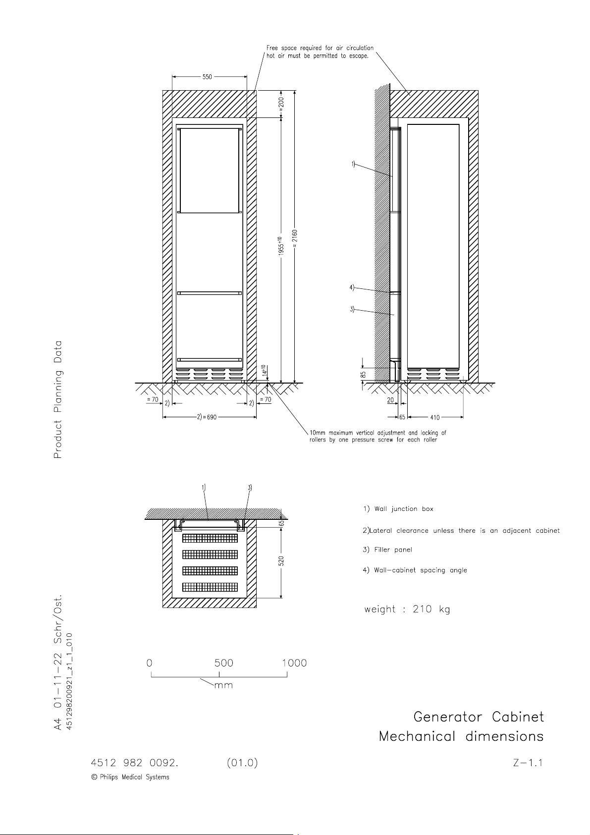
Generator cabinet: Mechanical dimensions Z--1.1................................
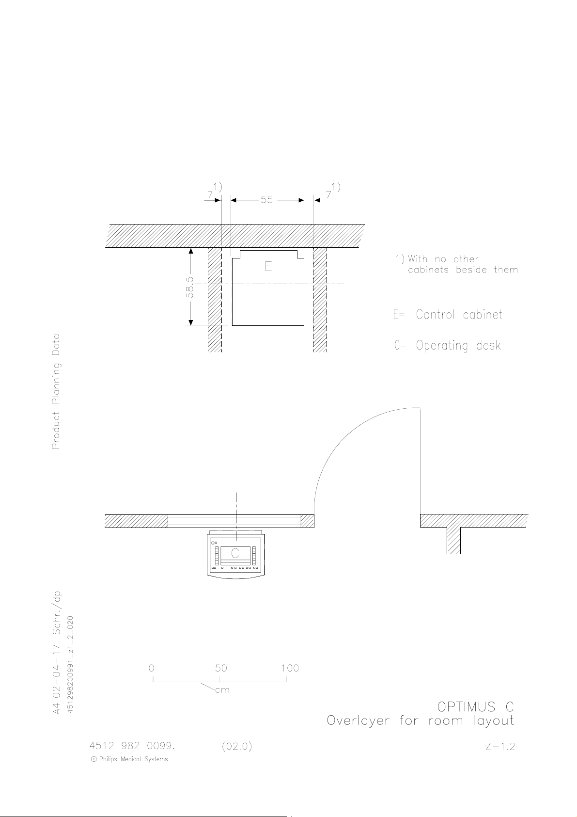
Overlayer for room layout Z--1.2..............................................
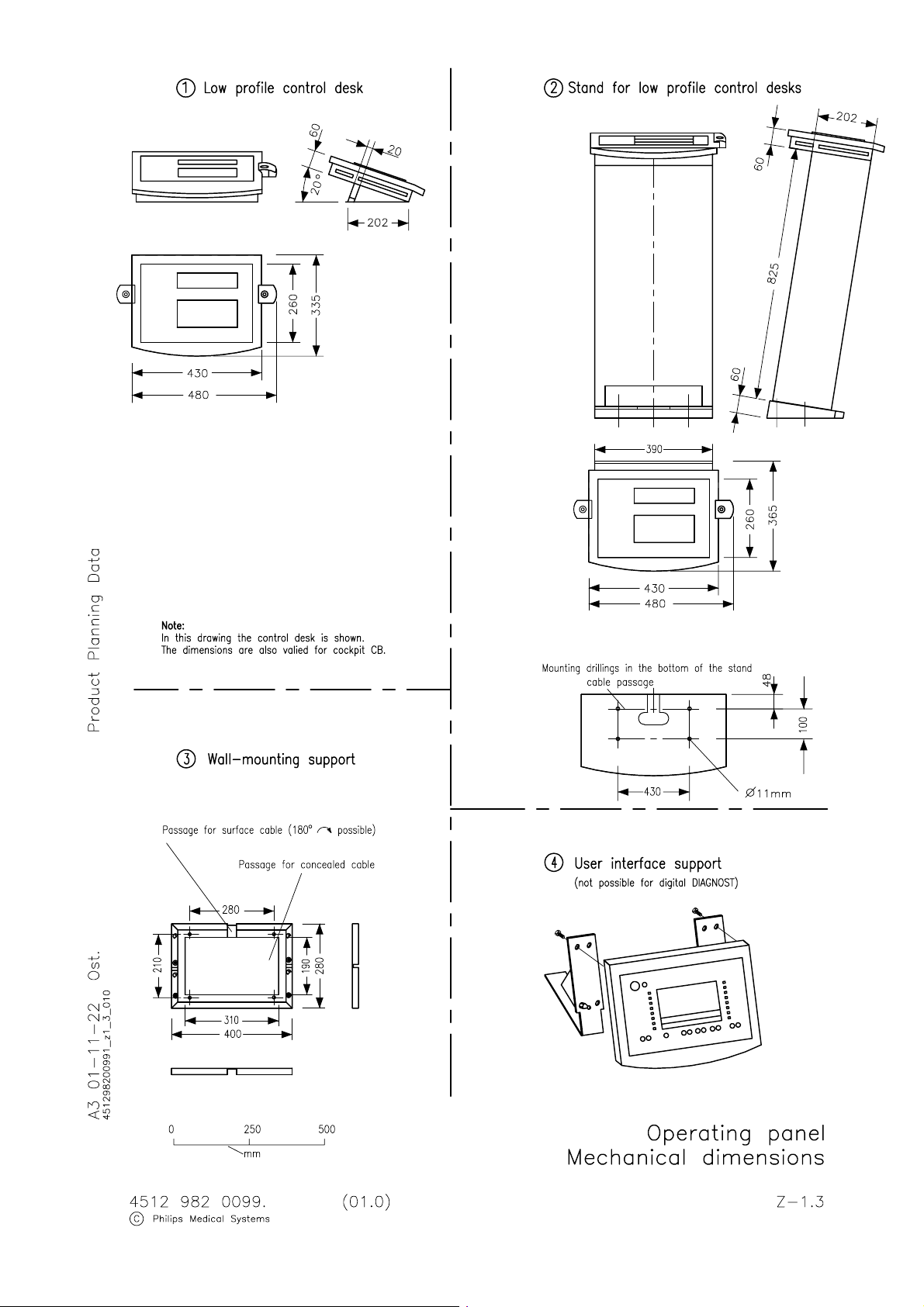
Operating panel: Mechanical dimensions Z--1.3.................................
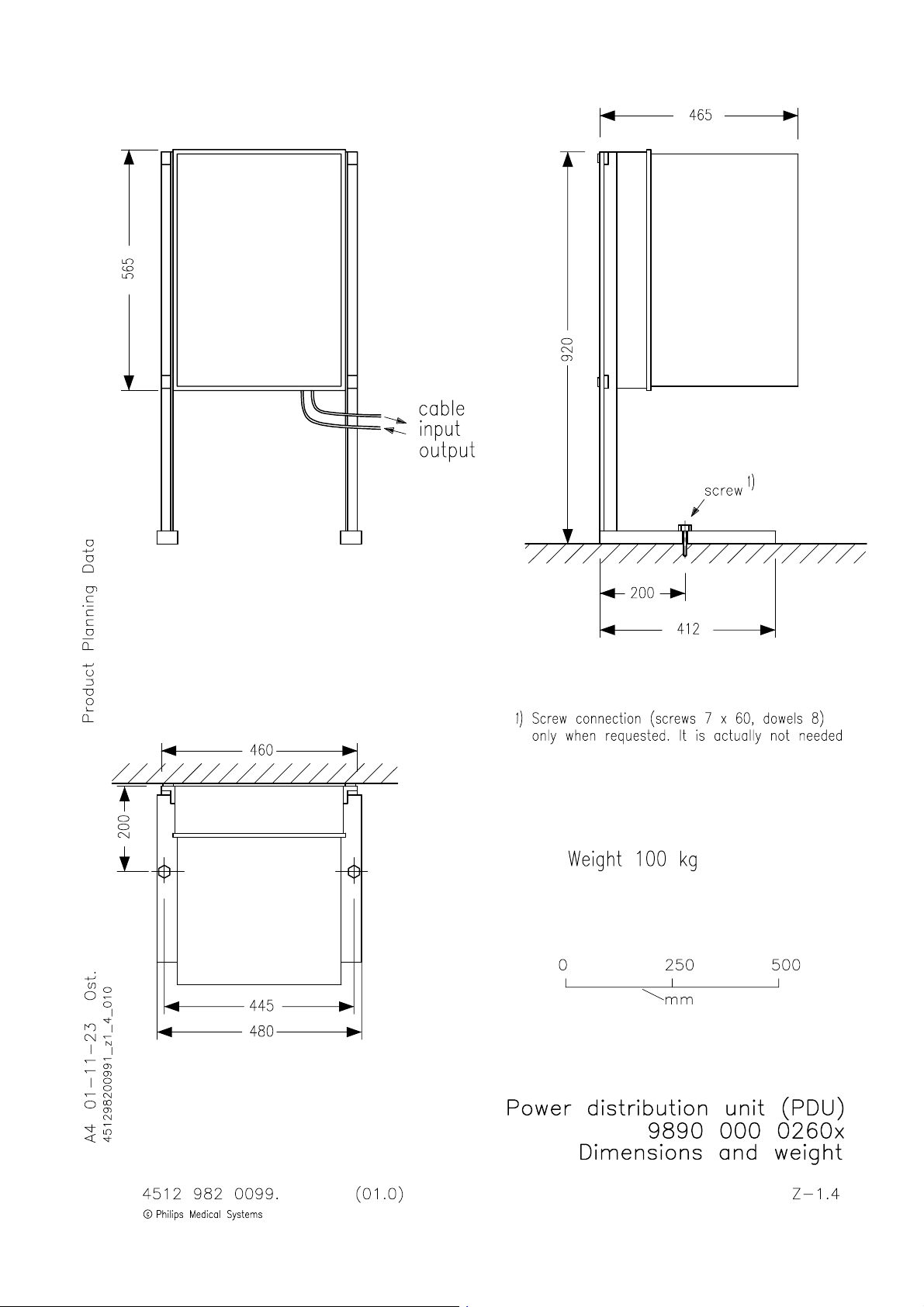
Power Distribution Unit: Dimensions and weight Z--1.4...........................
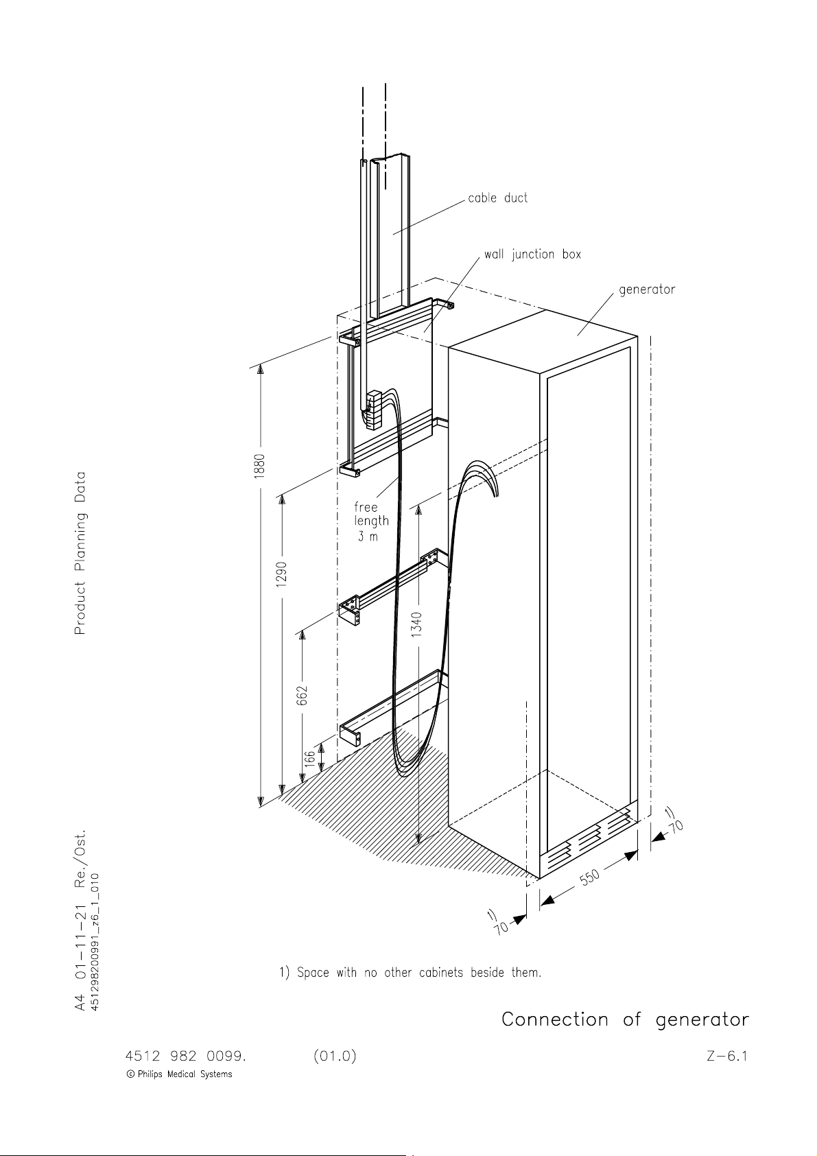
Connection of generator Z--6.1...............................................
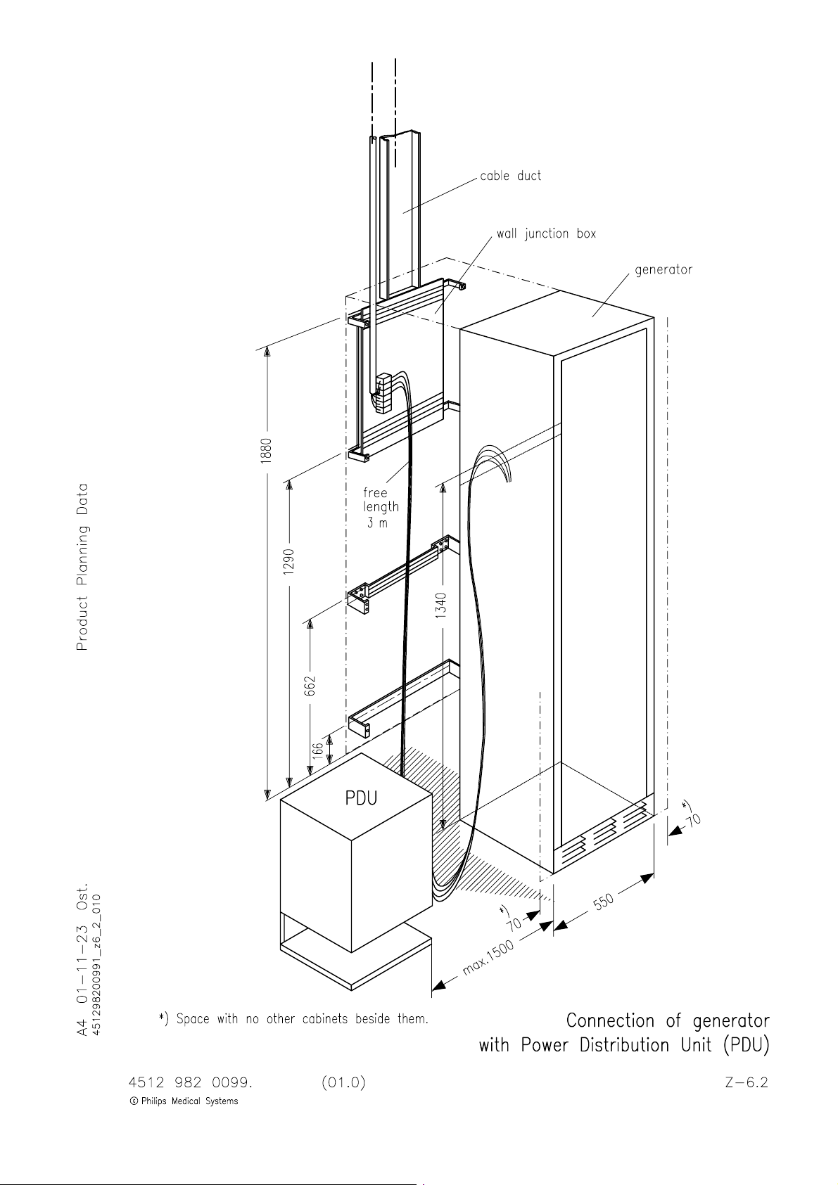
Connection of generator with PDU Z--6.2......................................
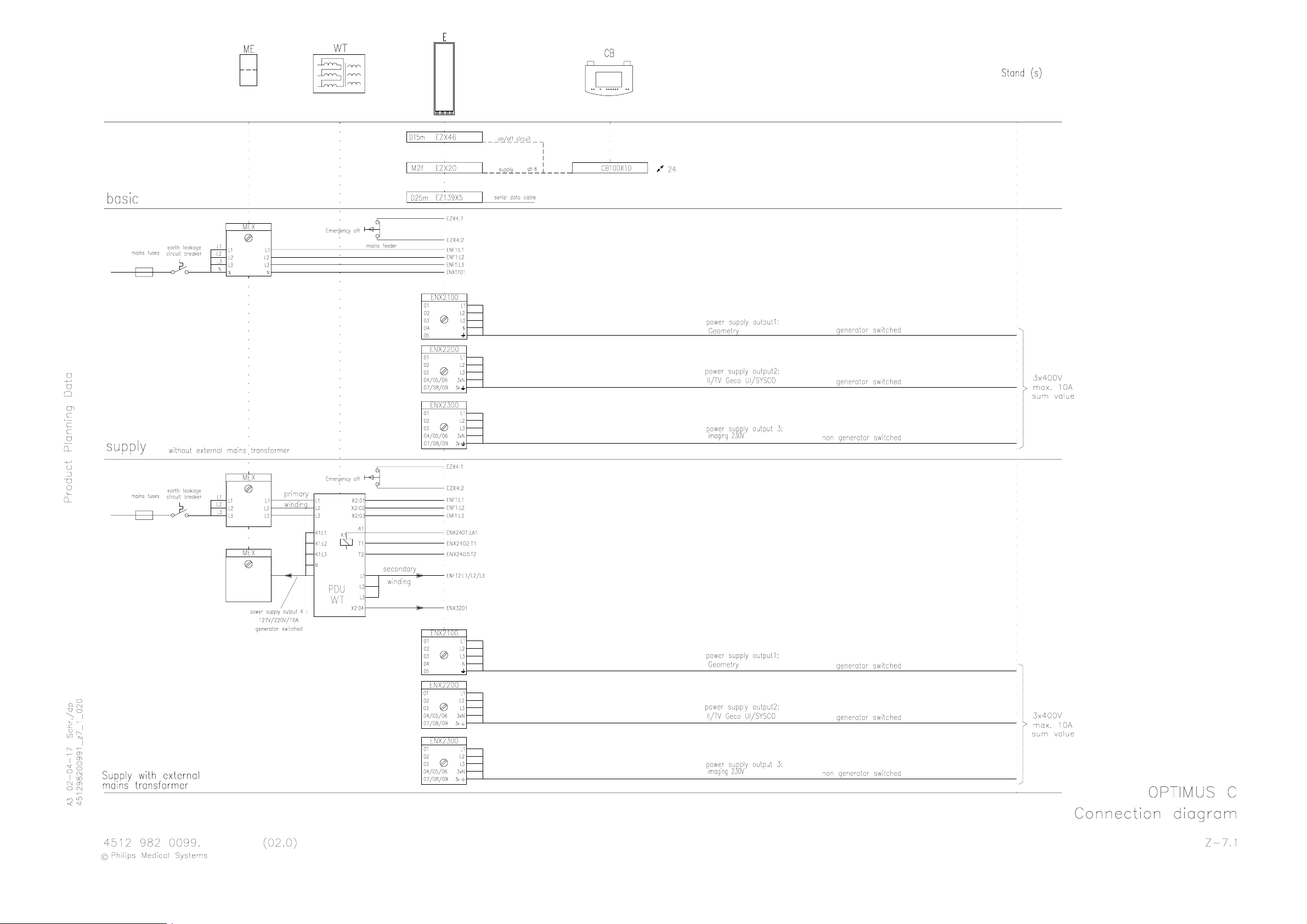
Connection diagram Z--7.1...................................................
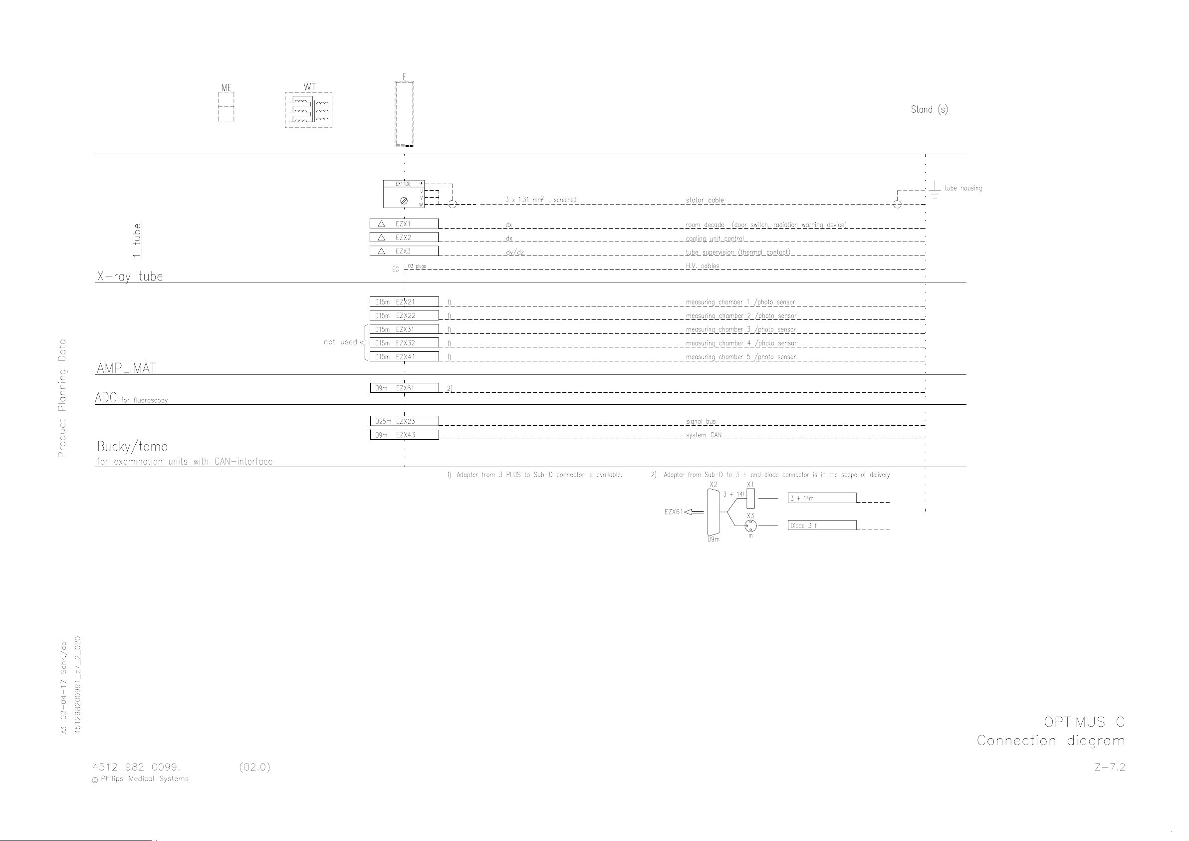
Connection diagram Z--7.2...................................................
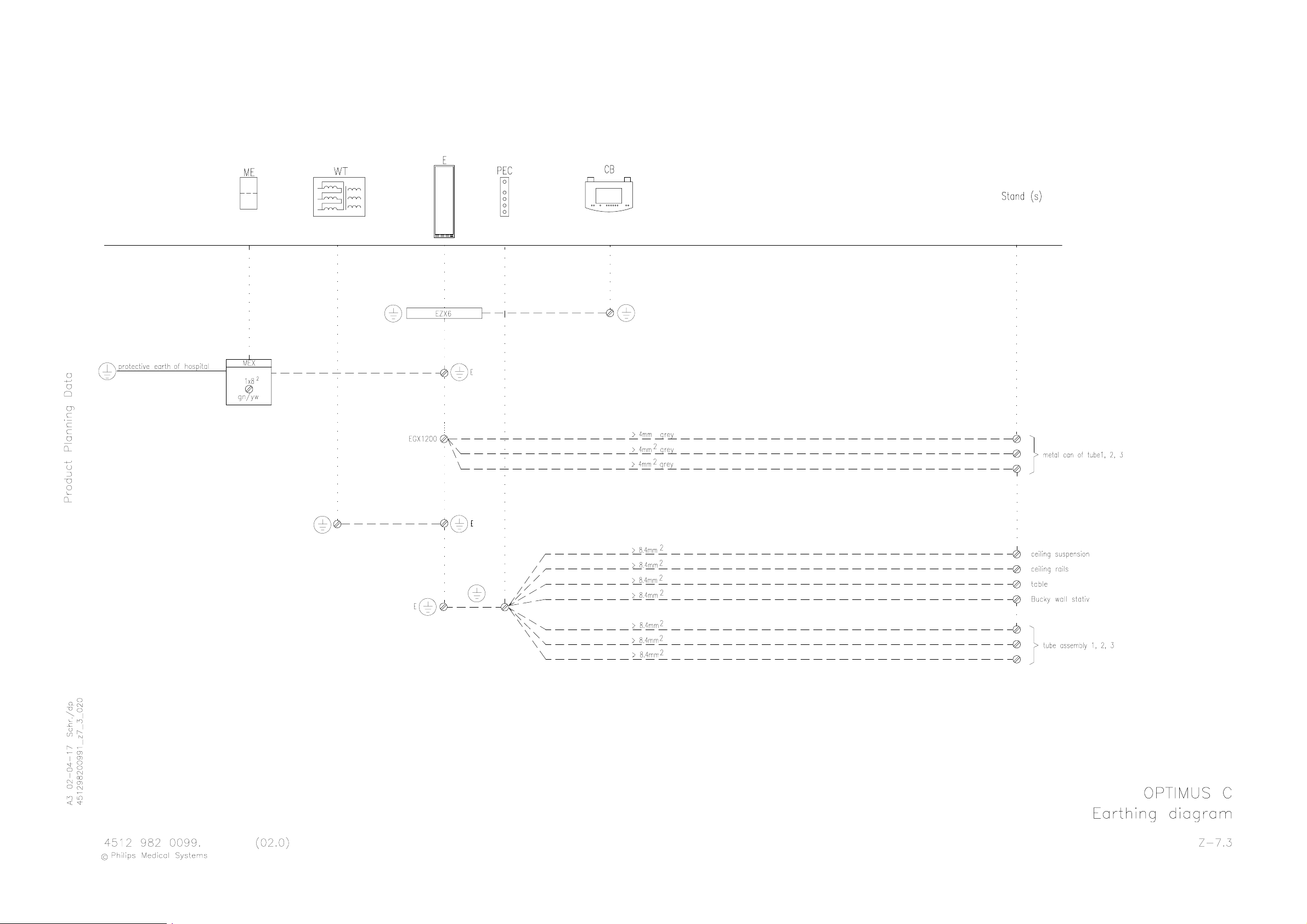
Earthing diagram Z--7.3.....................................................
Legend for earthing and cabling diagram Z--7.10.................................
OPTIMUS C (a/02.1)
OPTIMUS_C_1_a021_inh
E 2003 Philips Medical Systems
ALL RIGHTS RESERVED
1--0.1
Page 6

OPTIMUS C
INTRODUCTION AND TECHNICAL DATA
1. Product information
The Optimus family of generators for radiography is based on computer-controlled converter technology.
The converter operates in the non-audible frequency range.
Applicable options can be enabled by releasing software modules using customized PAL ICs depending on the
respective order.
Control between the internal Function Units (FUs) and the external online equipment takes place by a CAN bus.
Safety-relevant signals are transferred directly on the so-called “Signal bus”.
1.1. Applications
-- Radiography
-- Tomography
-- Fluoroscopy
1.2. Options
1.2.1. Hardware options
-- Mains transformer PDU: 400 -- 480V; 50 / 60Hz,
also for 400V mains supply without neutral lead N
with taps for 400 / 440 / 460 / 480V 9890 000 0260x......................................
-- Mains transformer: 190--390V; 50 / 60Hz
with taps for 190 / 200 / 207 / 220 / 230 / 240 / 250 / 343 / 380 / 390V
max. 50kW! 9803 720 8100x..........................................................
1.2.2. Software options
Software options are provided via the function key (see also 5Z--1, EZ 139 Central Unit D38).
Additional hardware components are not required.
All system options are available.
All Optimus C have the same function key configuration, there is only a difference in the power class 50/65/80kW.
2. Compatibility
2.1. Generator components
-- Base OPTIMUS C 9890 000 0219x....................................
-- H.V. transformer R/F 1 tube, 50kW 9890 000 0270x.. .................
-- H.V. transformer R/F 1 tube, 65/80kW 9890 000 0272x.. ...............
-- 50kW extension -- R/F 9890 000 0274x................................
-- 65kW extension -- R/F 9890 000 0275x................................
-- 80kW extension -- R/F 9890 000 0276x................................
-- Firmware Rel. 1.2 9890 000 0254x....................................
OPTIMUS C (a/02.1)
OPTIMUS_C_1_a021
E 2002 Philips Medical Systems
ALL RIGHTS RESERVED
1--1
Page 7

OPTIMUS CINTRODUCTION AND TECHNICAL DATA
C
2.2. Tubes
Recommended standard tubes:
-- RO 17 50
-- SRM 06 12
-- SRO 25 50
-- SRO 33 100
Further compatible tubes:
-- RO 12 30 -- SRO 09 51 -- SRO 20 55
-- RO 16 48 -- SRO 13 30 -- SRO 22 50
-- RO 30 50 RE -- SRO 20 50 -- SRO 32 100
Compatible tube housings:
-- ROT 350
-- ROT 351
-- ROT 504
The latest information on further tubes which are connectable is available at the service center Hamburg.
2.3. System components
-- DuoDiagnost GEOMETRY 9890 000 0290x............................
-- Stand for operating panel 9890 000 0244x.............................
-- Wall mounting of operating panel 9890 000 0245x.......................
-- User interface support 9890 000 0283x................................
-- Cable set for COCKPIT 9890 000 0279x...............................
3. Mechanical data
For installation dimensions and weights see drawings Z--1.1.
Transport data:
Weights [kg] Dimensions [cm]
ase no.Contents
-- Generator cabinet
1
-- Operating panel
-- Cables
net gross length width height
178 226 210 82 84
2 -- H.V. generator; 1--tube version 73 100 77 67 80
(a/02.1)1--2
E 2002 Philips Medical Systems
ALL RIGHTS RESERVED
OPTIMUS C
OPTIMUS_C_1_a021
Page 8

OPTIMUS C
INTRODUCTION AND TECHNICAL DATA
4. Environmental data
The environmental data comply with to PMS standard UXW 13600.
4.1. Electrical environment
Class S0 -- Dedicated mains supply, 3 phases and neutral. Thus single phase voltage is also available.
A low impedance, permanently installed connection, fed in by the step down transformer of the hospital to supply
large systems like in MR, CT and X--ray departments is required.
Note
Use always a mains cable with 4 wires and concentric PE--shield, type NYCY.
4.2. Climatic conditions
Ambient temperature 10_C--40_C...................
Relative humidity 15% -- 90%; no condensation.......................
Relative atmospheric pressure 70kPa -- 110kPa...........
4.3. Emission
Heat dissipation max. 1200W; average per hour........................
Noise level, normal operation ≈ 46dBA............
Noise level, maximum power operation ≈ 55dBA....
EMC IEC 950..................................
To avoid any possible annoying noise of the implemented fans it is advisable to install the generator cabinet
outside the examination room.
OPTIMUS C (a/02.1)
OPTIMUS_C_1_a021
E 2002 Philips Medical Systems
ALL RIGHTS RESERVED
1--3
Page 9

5. Electrical data
withexternaltransformerPDU(option
)
I
3+1x1
0
2
(L1,L
2,L
3,PE)
5.1. Power data and mains conditions
Voltag e
50kW 65kW 80kW
Mains voltage 3 x 400V ±10% (415V
3 x 400 / 440 / 460V ±10% *
6%
3 x 480V
=*=
The following connection cables are recommended:
+
|
--10%
+6%
/ 380V
*
-- 5 %
OPTIMUS CINTRODUCTION AND TECHNICAL DATA
)
nput:
Output: 4 x 4mm
4+1x4mm
3 x 1,5mm
mm
2
Generator supply 3 x 400V
2
Device supply 3 x 220V (option)
2
Switch control and temperature supervision
3 x 190 ... 343V ±10% **
** = with external transformer; max. 50kW (option)
Frequency
50kW 65kW 80kW
Mains frequency 49 ... 61Hz
(a/02.1)1--4
E 2002 Philips Medical Systems
ALL RIGHTS RESERVED
OPTIMUS C
OPTIMUS_C_1_a021
Page 10

OPTIMUS C
(
)
A
INTRODUCTION AND TECHNICAL DATA
Max. mains current
Voltag e
50kW 65kW 80kW
Exposure: 400V 145A 190A 230A
440V 135A 180A 215A
460V 125A 170A 210A
480V 120A 160A 205A
190V 300A -- --
Short--time power
consumption
100kVA 132kVA 160kVA
[I x U x √3]
Fluoro: 400V -- 8A
480V -- 7A
Fuse protection
slow blow
Connected load
[I
xUx√3]
Fuse
Emergency static
power supply: (Inverter)
dynamic
(Diesel generator
with flywheel mass)
35A
100A at ≤ 240V
25kVA 35kVA
Short--time power consumption
[I x U x √3]
Connected load
[I
xUx√3]
Fuse
50
Mains resistance
Voltag e
50kW 65kW 80kW
400V ≤ 300mΩ ≤ 200mΩ
440V ≤ 350mΩ ≤ 240mΩ
460V ≤ 350mΩ ≤ 240mΩ
480V ≤ 400mΩ ≤ 300mΩ
480V valid for DOD only ≤ 300mΩ ≤ 240mΩ ≤ 180mΩ
Note
500m
Ω
is the absolute max. mains resistance.
OPTIMUS C (a/02.1)
OPTIMUS_C_1_a021
E 2002 Philips Medical Systems
ALL RIGHTS RESERVED
1--5
Page 11

5.2. Power supply for application
Generator power
Supply 50kW 65kW 80kW
OPTIMUS CINTRODUCTION AND TECHNICAL DATA
Output 1 230V / 400V; generator switched and protected ----> I
Output 2 230V / 400V; generator switched and protected ----> I
Output 3 230V / 400V; generator not switched and protected ----> I
Sum value I
max(1+2+3)
≤ 10A
Only with external
transformer PDU
Output 4 127V / 220V generator switched and protected ----> I
Output 5 double socket 127V / 15A to phase L1;
generator not switched and protected ----> I
Sum value I
max (4 +5)
≤ 16A
5.3. Operating data
Generator power
1
2
3
4
5
Data
50kW 65kW 80kW
Exposure: Tube current 1 ... 650mA 1 ... 900mA 1 ... 1100mA
Tube voltage 40 ... 150kV in kV-- or %--steps
mAs product 0,5 ... 850mAs
Exposure time 1ms ... 6s / 16s
Exposure frequency ≤ 12exp./s
Interfacing option for door contact, external radiation warning indicator
Fluoro: Tube current 0,25 ... 6mA
Tube voltage 40 ... 110kV
kV/mA curves 3
Setting time ≤ 1s
(a/02.1)1--6
E 2002 Philips Medical Systems
ALL RIGHTS RESERVED
OPTIMUS C
OPTIMUS_C_1_a021
Page 12
OPTIMUS C
5.4. Power supply
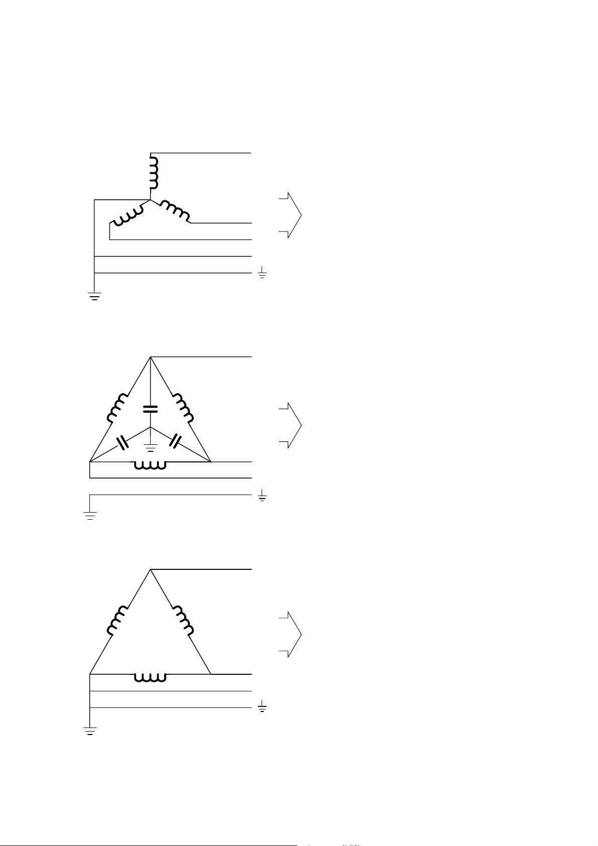
5.4.1. Type of power supply
3 phase WYE
INTRODUCTION AND TECHNICAL DATA
L1
L2
L3
(N)
3 phase DELTA,
balanced earth or floating
L1
L2
L3
X-ray
installation
X-ray
installation
-- 400V
-- 440V / 460V / 480V with
external mains transformer PDU
9890 000 0260x.
-- Neutral not required if the external
mains transformer PDU
9890 000 0260x is ordered.
-- 190V ... 343V with
external mains transformer
9803 720 8100x (max. 50kW).
-- External mains transformer PDU
9890 000 0260x is required.
-- 400V / 440V / 460V / 480V
-- 190V ... 343V with
external mains transformer
9803 720 8100x (max. 50kW).
3 phase DELTA,
grounded
L1
-- External mains transformer PDU
9890 000 0260x is required
(requires modification at the
EMC-- filter of the kV power unit).
X-ray
installation
L2
L3
Caution!
Ensure the sequence of phases in the wall junction box corresponds to designations L1, L2, L3.
OPTIMUS C (a/02.1)
OPTIMUS_C_1_a021
E 2002 Philips Medical Systems
ALL RIGHTS RESERVED
-- 400V / 440V / 460V / 480V
1--7
Page 13
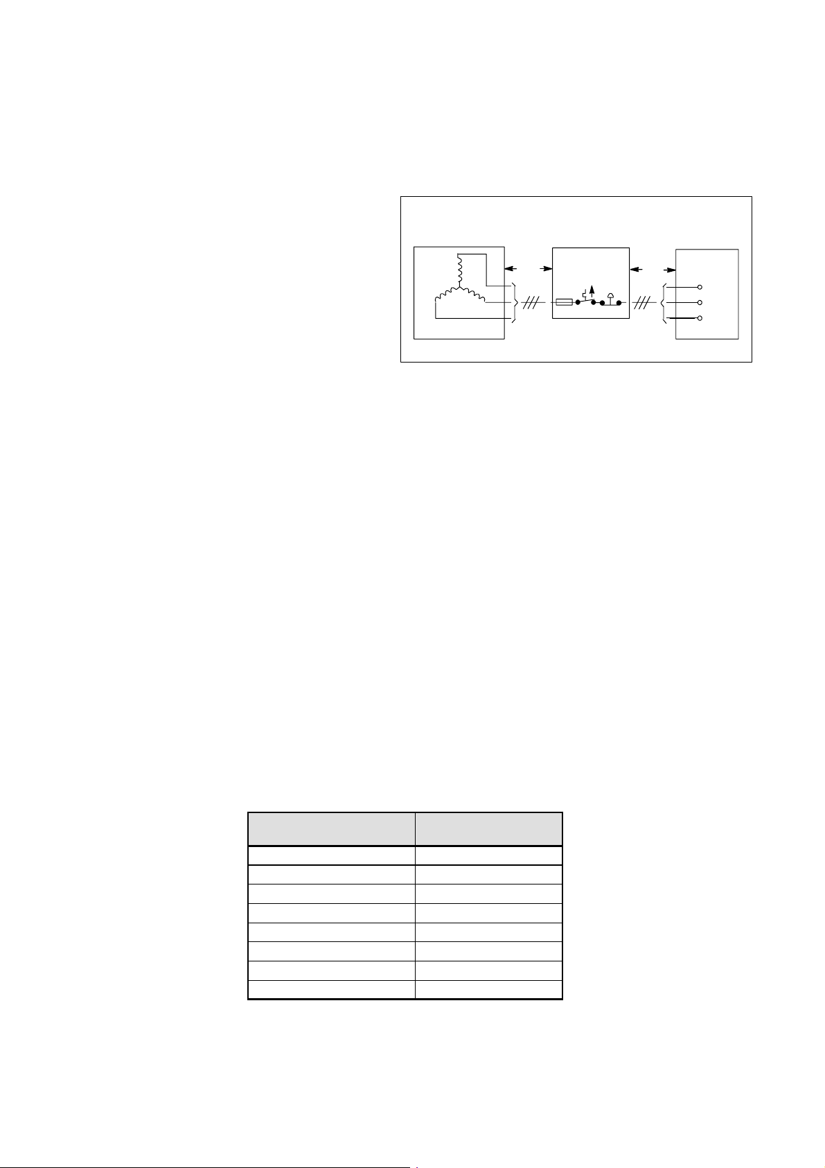
5.4.2. Calculating the mains resistances
Note
The cross section of lead l
must not exceed 25mm2. (See figure below).
3
OPTIMUS CINTRODUCTION AND TECHNICAL DATA
If possible the sum of R
smaller than the R
requires.
XG
0,R1,R2
and R3should be
R
+R1+R2+R3<R
0
With higher internal mains resistances the generator
output is reduced correspondingly.
R
designates the mains resistance of the distributor transformer
0
R
depends on the length of lead l1between distributor transformer and mains distributor
1
L1
L2
L3
l
1
and on the selected cross section as well:
==> R
R
consists of upstream elements such as:
2
1=l1
× R
Cu
RCufrom table below
-- Emergency-OFF switch 4.0mΩ.................
-- Earth-leakage circuit breaker 5.5mΩ............
l
3
XG
MEX 100
L1
L2
L3
357J94
-- Fuse 5.5mΩ.................................
-- Surge arrester WN 23.0mΩ...................
R
depends on the length of lead l3between mains distributor and wall junction box
3
and on the selected cross section as well:
==> R
3=l3
× R
Cu
RCufrom table below
The resistances consider the go and return lines so that the calculation can be based on simple cable lengths.
Copper cross section
[mm
2
]
Resistance R
[mΩ/m]
Cu
16 2.19
25 1.4
35 1.0
50 0.7
70 0.5
95 0.38
120 0.30
150 0.24
Note
500m
Ω
is the absolute max. mains resistance.
(a/02.1)1--8
E 2002 Philips Medical Systems
ALL RIGHTS RESERVED
OPTIMUS C
OPTIMUS_C_1_a021
Page 14

OPTIMUS C
INTRODUCTION AND TECHNICAL DATA
5.4.3. Earth-leakage circuit breaker
To be provided between mains fuse and X-ray installation depending on local regulations.
Siemens earth-leakage circuit breaker:
-- Order No.: 5SZ3 466 OKG00
-- Rated fault current 30mA
-- Rated current 63A
-- Connection terminals for wire cross sections of up to 25mm
2
5.4.4. Emergency--OFF device
To be provided depending on local regulations.
There are 2 possibilities:
1. All the emergency--OFF buttons are connected in series and looped into the switch--ON circuit (12VDC) of the
generator.
2. The emergency--OFF circuit acts on an external mains contactor which switches OFF the power before it is
fed into the generator.
6. Tools
-- Service engineer standard tool kit
-- Service-PC:
IBM-compatible, 640kB RAM, 3.5” floppy disk drive, ≥ 1 serial port
-- Installation and service software OMC: 4512 116 024xx.
Supplied on a floppy disk within this generator service manual.
-- PC-hardkey (DIAGGEN):
Necessary to carry out the installation and to run the service software (special programmings, fault finding).
-- 0-modem cable:
Minimum length is distance between generator cabinet and operating desk.
Male 25-pole D-Sub connector at the generator side.
A 5m data cable of bucky controller can be used: 4512 130 5693x
-- Mains resistance measuring instrument
-- Dose measuring instrument
-- mAs--meter
-- Multimeter
-- Digital oscilloscope with 2-beam memory
-- Recommended PLCC extraction tool (AMP 822154--1): 2422 487 89772
7. Traceable items
The following items have serial numbers of the following format when delivered ex factory:
1. Generator cabinet 6 digit serial number........
2. H.V. tank 7 digit serial number................
OPTIMUS C (a/02.1)
OPTIMUS_C_1_a021
E 2002 Philips Medical Systems
ALL RIGHTS RESERVED
1--9
Page 15

8. Preparation
Connection of the generator: see drawing Z--6.1................
Connection of the generator with PDU: see drawing Z--6.2.......
Operating panel: see drawing Z--1.3..........................
Connection diagram: see drawing Z--7.1/.2.......................
Earthing diagram: see drawing Z--7.3.........................
Legend for earthing and cabeling: see drawing Z--7.10...........
8.1. Installation material
To be ordered from the service department of PMS Hamburg:
-- Wall junction box 4512 103 7538x.............................
2
inclusive connection block (25mm
-- Relay for radiation warning indicator 4512 100 4523x............
1 interface relay with a floating contact (230V/1A) is included in the scope of delivery of the generator.
8.2. Cables
) for mains supply and connection block (10mm2) for unit supply.
OPTIMUS CINTRODUCTION AND TECHNICAL DATA
H.V . cables
with O3 / O3 plugs: 9806 402 6xx02................................
length: 6m -- 30m in steps of 2m...........................................
capacity: 155pF/m.........................................
diameter: 16.5mm........................................
The cable length is indicated by the 9th and 10th digit of the numeric code.
Thermal contact cable
-- 2-wire screened for 1 excess temperature switch 4512 100 66151..................
-- 10-wire screened for additional supervision like
temperature alarm switch, buzzer, selection indicator 0722 215 19005..............
Stator cable
-- Tube SRM--0612 : 3x 1,31 mm
2
, screened with uMNL--connector 3322 405 14191....
-- all other tubes :
2
3×1.31mm
, screened 0722 215 02054........................................
AMPLIMAT cable
with D-Sub and 3--Plus plug:
12m 9890 000 01721......................
16m 9890 000 01731......................
20m 9890 000 01741......................
24m 9890 000 01751......................
Note
The above described cables are part of the pre--assembled systems.
(a/02.1)1--10
E 2002 Philips Medical Systems
ALL RIGHTS RESERVED
OPTIMUS C
OPTIMUS_C_1_a021
Page 16

OPTIMUS C
INTRODUCTION AND TECHNICAL DATA
8.3. Manpower
At least two persons are necessary to insert the H.V. tank in the generator cabinet.
The weight is about 73kg.
9. Planned maintenance
The technical documentation for carrying out maintenance work in compliance with the applicable regulations are
available at the responsible authority of Philips Medical Systems.
The importance of having maintenance implemented is pointed out to the operator in the operating instructions.
It must be guaranteed that the person carrying out maintenance work knows about the respective national
regulations and that this person observes these regulations throughout all steps of maintenance work.
OPTIMUS C (a/02.1)
OPTIMUS_C_1_a021
E 2002 Philips Medical Systems
ALL RIGHTS RESERVED
1--11
Page 17
Page 18
Page 19
Page 20
Page 21
Page 22
Page 23
Page 24
Page 25
Page 26

Page 27

OPTIMUS C
1. Installing the wall junction box 2--1........................................
2. Mounting the H.V. generator in the cabinet 2--2.............................
2.1. Mounting of the H.V. generator in the cabinet 2--2..............................
2.2. Electrical connection of the H.V. generator 2--3................................
3. Installing the operating panel 2--4.........................................
4. Electrical connection 2--5.................................................
4.1. Earthing 2--5..............................................................
4.2. Mains connection 2--5......................................................
4.2.1. Mains connection of the generator 2--5.......................................
4.2.2. Mains connection of the PDU 2--6...........................................
4.3. Stator connection 2--7......................................................
4.3.1. Shielding 2--7.............................................................
4.3.2. Connection 2--8...........................................................
4.4. Signal cables 2--9.........................................................
4.4.1. Room decade cable 2--9....................................................
4.4.2. Tube supervision 2--10......................................................
4.4.3. CAN interface 2--10.........................................................
4.4.4. Dose input 2--10............................................................
4.4.5. Dose rate input 2--10........................................................
4.5. H.V . cables generator side 2--11..............................................
4.6. Emergency--OFF circuit 2--1 1................................................
5. Hardware programming 2--12...............................................
6. Switch--ON of the generator 2--13...........................................
7. Installation software XRGSCOPE 2--13......................................
7.1. PC and generator settings to avoid problems during up/downloading of
7.2. Installation procedure 2--14..................................................
8. Setting-to-work overview 2--17.............................................
8.1. Configuration 2--17.........................................................
8.1.1. Date and time 2--17.........................................................
8.1.2. Mains data 2--17...........................................................
8.1.3. Tube data set 2--18.........................................................
8.1.4. Tube speed selection 2--18..................................................
8.1.5. Tube limits 2--18............................................................
8.1.6. Capacitance of tube connection 2--19.........................................
8.1.7. Tube operating modes 2--20.................................................
8.1.8. Disable tube 2--20..........................................................
8.2. Tube adjustment 2--21......................................................
8.2.1. Tube conditioning 2--21......................................................
8.2.2. Tube adaptation 2--25.......................................................
8.3. Dose rate control 2--28......................................................
8.3.1. AMPLIMAT sensitivity 2--28..................................................
8.3.2. Screen/film combinations 2--28...............................................
8.3.2.1. Automatic DRC processing 2--29.............................................
8.3.2.2. Manual DRC processing 2--30................................................
8.3.2.3. Density correction for AEC technique (option) 2--31.............................
INSTALLATION
INSTALLATION
TEXT
Contents 2--0.1............................................................
CU complete files 2--13......................................................
OPTIMUS C (a/02.1)
OPTIMUS_C_2_a021_inh
E 2002 Philips Medical Systems
ALL RIGHTS RESERVED
2--0.1
Page 28

OPTIMUS CINSTALLATION
8.3.3. Image intensifier (II) 2--32....................................................
8.3.4. Fault exposure detection 2--32...............................................
8.3.5. Continuous fluoroscopy 2--32................................................
8.4. Application limits 2--34......................................................
8.4.1. X--mode limits 2--34.........................................................
8.4.2. Thoravison limits 2--34......................................................
8.4.3. Overload-dependent limits 2--34..............................................
8.5. Area exposure product calculatio(option) 2--35..................................
8.6. Acceptance test 2--35.......................................................
8.7. Backup of all configuration data 2--35.........................................
9. Labels 2--36...............................................................
10. Final installation work 2--36................................................
DRAWINGS
Data sets of chambers 2Z--4.........................................................
Labelling 2Z--10.....................................................................
E 2002 Philips Medical Systems
ALL RIGHTS RESERVED
OPTIMUS C(a/02.1)2--0.2
OPTIMUS_C_2_a021_inh
Page 29

OPTIMUS C
INSTALLATION
1. Installing the wall junction box
S Mount the wall junction box at the place where the generator is intended to be installed.
(See drawing “Connection of generator” in section 1 and manual UNIT 4512 103 75380 for wall junction boxes).
S If necessary, install the optional surge arrester WN inside the wall junction box.
(See surge arrester documentation.)
S If applicable, mount the filler panels of the generator to the wall junction box.
S Have the mains cable present at the clinic connected to mains terminal MEX by a person who is authorized for
this job.
S Check the phase sequence of L1, L2 and L3.
Warning!
Switch OFF the mains supply present at the clinic and make sure that it cannot be switched
ON again accidentally
.
OPTIMUS C (a/02.0)
OPTIMUS_C_2_a021
E 2002 Philips Medical Systems
ALL RIGHTS RESERVED
2--1
Page 30
OPTIMUS CINSTALLATION
2. Mounting the H.V. generator in the cabinet
2.1. Mounting of the H.V. generator in the cabinet
Caution!
Do not tilt the H.V. generator while transporting it.
In case of a tilting angle larger than 45_, the setting-to-work of the generator can be started not before a
waiting time of about 8 hours has passed. Otherwise the H.V. generator may be destroyed by electrical
sparkover.
S Unpack generator cabinet E.
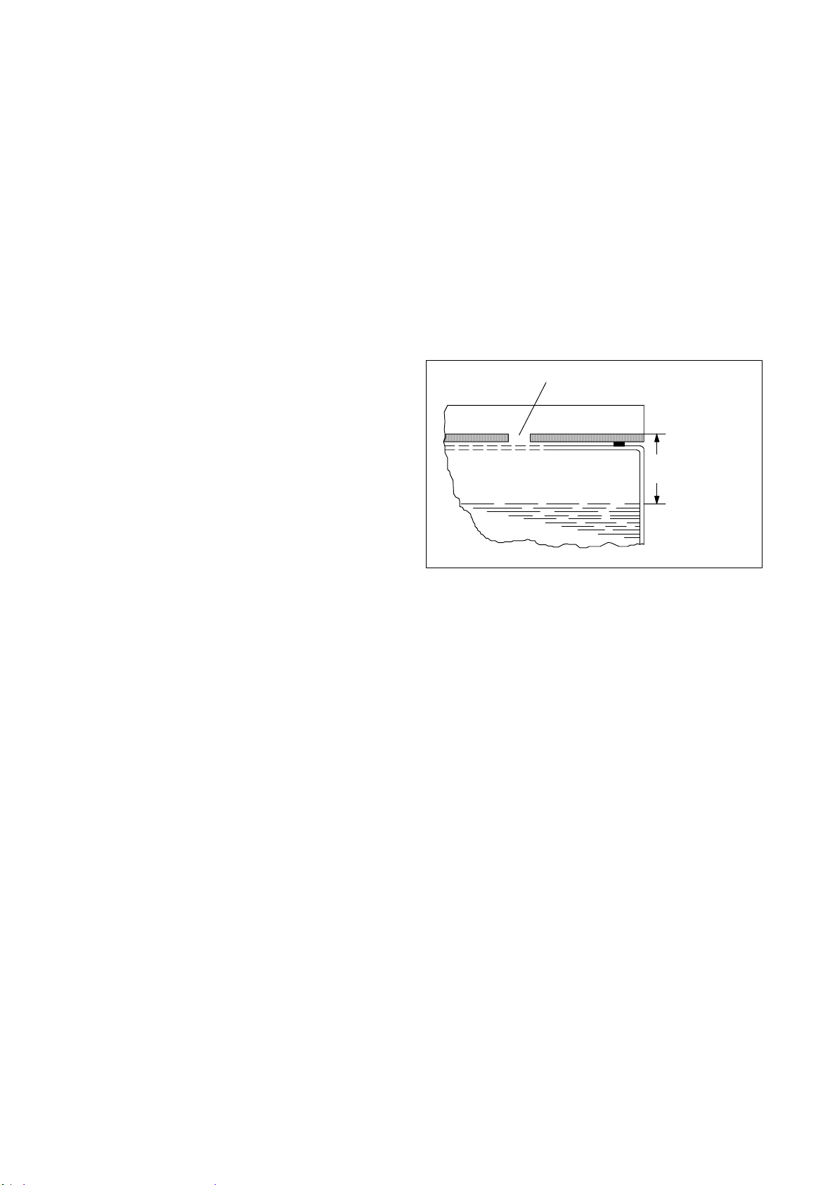
S In case the packing material is strongly soiled with
oil check the oil level. Repair it if necessary.
deaerating hole
Tolerance: 2mm
Oil: Shell Diala G in 2.5l container
4512 148 43172
24mm at 20 - 30_C
22mm at 30 - 36_C
329H97
S Remove the deaerating screw completely from the cover of the H.V. generator. Only this way the precision of
the high voltage measuring divider corresponds to the specification.
In case of return shipment of the H.V. generator this screw must be fixed again. Therefore, keep the screw laying
on top of the cover.
Caution!
Make sure that no foreign matter falls into the oil. Otherwise the transformer must be exchanged.
S Take the two transport bars from the rear side of the cabinet.
S Lift the H.V. generator into the generator cabinet with the transport bars.
The 4 connecting bolts GX1001 to 1004 must point at the front of the generator cabinet.
E 2002 Philips Medical Systems
ALL RIGHTS RESERVED
OPTIMUS C(a/02.0)2--2
OPTIMUS_C_2_a021
Page 31

OPTIMUS C
Generator
R
k
Routethecablesalongthefrontandlef
t
Seedrawingp
age2--4
thereasonofkVsymmetry
Not
e
k
W
Seedrawingp
age2--4
2.2. Electrical connection of the H.V. generator
S Connect the H.V. generator electrically:
INSTALLATION
Generator
version
50/65/80kW
50kW
Connection
emar
from <------> to
E1 (GND) <------> GX1100 (GND) Ground
ZX12 <------> G100X15
ZX35 <------> G100X14
Route the cables alongthe front and left-hand edge of the H.V. generator. Fix them.
Twist the cables!
QC13:1 <------> GX1003
Note
The sequence of the connecting bolts is not
in numerical order.
Push the screening cap forward over the
QC03:1 <------> GX1002
connecting bolts and tighten it. Attach the
converter cables including the screening to
the screening cap with cable ties.
The 50kW version might have direct links
GX1001 <------> GX1003
on each side or a link on one side and a
choke of 1 ... 6 loops on the other side for
.
.
65/80
GX1004 <------> GX1002
QC13:1 <------> GX1001
QC03:1 <------> GX1002
2QC13:1 <------> GX1003
2QC03:1 <------> GX1004
Note
Do not change these links or chokes.
Twist the cables!
The sequence of the connecting bolts is not
in numerical order.
.
Push the screening cap forward over the
connecting bolts and tighten it.Attach the
converter cables including the screening to
the screening cap with cable ties.
OPTIMUS C (a/02.0)
OPTIMUS_C_2_a021
E 2002 Philips Medical Systems
ALL RIGHTS RESERVED
2--3
Page 32

OPTIMUS CINSTALLATION
S Turn the two earthing angles of the H.V . generator outward and screw them on to the members of the cabinet.
converter cables (twisted)
fixed at the screening cap
earthing angles
Connection of
50kW version
screening cap
terminal for the screen
of the filament cable
fixing signal cable
199H96
Connection of
65/80kW version
QC13:1
Twist the cable
Link or choke
X1001
QC 03:1
Link or choke
X1002X1003 X1004
3. Installing the operating panel
See Unit Manual COCKPIT for DuoDiagnost.
Twist the cables
QC13:1
QC03:1
X1001 X1003
X1002
2QC13:1
2QC03:1
X1004
E 2002 Philips Medical Systems
ALL RIGHTS RESERVED
OPTIMUS C(a/02.0)2--4
OPTIMUS_C_2_a021
Page 33

OPTIMUS C
Mai
INSTALLATION
4. Electrical connection
4.1. Earthing
See ”Earthing diagram” in section 1.
4.2. Mains con n ectio n
4.2.1. Mains connection of the generator
Warning!
Switch OFF the mains supply present at the clinic and make sure that it cannot be switched
ON again accidentally
See ”Connection diagram” in section 1.
S Measure the internal mains resistance at the terminal MEX with a suitable measuring instrument.
.
L1 - L2: R
L1 - L3: R
L2 - L3: R
= ............... mΩ
i
= ............... mΩ
i
= ............... mΩ
i
Required max. mains resistance at generator input:
ns voltage
30kW 50kW 65/80kW
190V * -- 40mΩ --
220V * 130mΩ 60mΩ --
240V * 160mΩ 80mΩ --
380V 500mΩ 300mΩ 200mΩ
400V 500mΩ 300mΩ 200mΩ
440V 500mΩ 350mΩ 240mΩ
460V 500mΩ 350mΩ 240mΩ
480V 500mΩ 400mΩ 300mΩ
Mains resistance
* with external mains transformer (max 50kW)
Maximum permissible internal mains resistance: 500mΩ
Internal resistance of Power Distribution Unit PDU: 20mΩ at 50Hz
23mΩ at 60Hz
OPTIMUS C (a/02.0)
OPTIMUS_C_2_a021
E 2002 Philips Medical Systems
ALL RIGHTS RESERVED
2--5
Page 34

OPTIMUS CINSTALLATION
Caution!
Connect phase wires in correct phase sequence.
S Connect the mains cable of the generator to terminal MEX: L1 / L2 / L3 within the wall connection box.
If the optional Power Distribution Unit PDU WT is fitted, connect the cables at that point to terminal WTX2.
S Connect the examination unit supply (max. 10A) to (230V / 400V):
Output 1 Geometry power ENX2101/...5
Output 2 I.I. / TV; GECO; UI; SYSCO ENX2201/...9
Output 3 Imaging ENX2301/...9
(Output 3not switched by generator)
4.2.2. Mains connection of the PDU
See delivered Unit Manual “Power Distribution Unit”.
E 2002 Philips Medical Systems
ALL RIGHTS RESERVED
OPTIMUS C(a/02.0)2--6
OPTIMUS_C_2_a021
Page 35

OPTIMUS C
INSTALLATION
4.3. Stator connection
4.3.1. Shielding
Caution!
To suppress interferences of the high-speed rotor control, the stator connections must be provided with
a 360_ screen at the tube and generator end.
General remarks:
-- SRM--0612 : 3322 405 14191..................
-- all othes tubes :
S Always use screened cables: 0722 215 02054.....
S Shorten the stator cable to the required length. Do not accommodate excess lengths at the generator.
S Keep stator cable separate from all the other signal cables to avoid interference.
S Earth the screen at both cable ends.
Screening procedure:
S Remove any enamel or dirt from the clamp
providing drag relief in the tube housing to make
sure the clamp is conductive.
S Remove the plastic covering around the clamp,
about 1cm (0.5”).
S Wrap copper foil around the visible screen of the
cable until the original diameter of the cable is
obtained.
S Remove the present red wire going from the
screen end to the earthing point of the tube
housing.
S Fix the screen of the stator cable with the clamp.
Ensure that the clamp is secured and the ground
contact works!
Wire must be discarded
Copper foil layers up to
the insulation diameter
ROT 350 fixing clamp
Screening of the stator cable.
327H97
OPTIMUS C (a/02.0)
OPTIMUS_C_2_a021
E 2002 Philips Medical Systems
ALL RIGHTS RESERVED
2--7
Page 36

4.3.2. Connection
Caution!
Do not mix up the phases, otherwise components of the rotor control may be destroyed.
OPTIMUS CINSTALLATION
At the tube end - only
SRM--0612
Note
The following steps are valid for SRM 0612 tubes only.
S Connect the stator cable with the MATE-N-LOCK
connector.
S Connect protective earth and earth of tube CAN as
shown in figure beside.
S Earth the screening of the stator cable at the tube
housing with the metallic clamp.
At the tube end - all other
tubes
S Place the jumpers across terminals 100 and 200
according to the figure.
Central connection
pointofprotective
earth
Connection
earth of
tube CAN
W
V
U Stator supply
U
101 202
XA
Connection to the
cap of the housing
100
123
V
W
109 210
S Connect the stator cable:
wire 1 ------> phase U
wire 2 ------> phase V
wire 3 ------> phase W
S Earth the screening of the stator cable at the tube housing with the metallic clamp.
SRO/RO
148H94
E 2002 Philips Medical Systems
ALL RIGHTS RESERVED
OPTIMUS C(a/02.0)2--8
OPTIMUS_C_2_a021
Page 37

OPTIMUS C
INSTALLATION
At the generator
end
See ”Connection diagram” in section 1.
S Connect the stator cable to the terminal EX1100
(U--V--W).
S Check the stator connection by measuring the
resistances:
U -- V = wire 1 -- 2 ≈ 11Ω
U -- W = wire 1 -- 3 ≈ 20Ω
V -- W = wire 2 -- 3 ≈ 9Ω
S If an inductance meter is available, measure the
following inductance values:
U -- V = wire 1 -- 2 = 57mH ±10%
V -- W = wire 2 -- 3 = 34mH ±10%
S Fix the screen below the screening clamp.
S Relieve the tension of the stator cable by a cable
tie.
4.4. Signal cables
E
rotor control
U
1
X1100
VW
2
3
cable tie
screening
clamp
tube
191H96
See: -- ”Connection diagram” in section 1.
-- Z1--6 ”Basic interface” in section “Schematic drawings”
4.4.1. Room decade cable
S Connect the door switches at the generator:
EZX1: 8 <------> switch <------> 10
or
E W B X 2 2 : 8 < -- -- -- > s w i t c h < -- -- -- > 1 0
In case no switch is present
l i n k : p i n 8 < -- -- -- > p i n 1 0
EZ150 K1:
max. switching and loading current = 1A
max. Load = 60VA AC
= 30W DC
Caution!
Make sure the polarity of the relay is correct.
EZX1
10
4
5
6
8
9
--
+
SW UN EX
PO26V
CMSW
RM DR CT
RM DR 0V
Door switch connection
wall junction box
ME
door switches
screen
U
= 230V
max
I
=1A
max
radiation
indication
(not required for
DuoDiagnost
systems)
OPTIMUS C (a/02.0)
OPTIMUS_C_2_a021
E 2002 Philips Medical Systems
ALL RIGHTS RESERVED
2--9
Page 38

4.4.2. Tube supervision
S Connect the thermal switch or the thermal sensor
of the tube housing assembly.
For U.S.A. and U.K. only:
S Connect the HHS-lamp to indicate the selected
tube housing assembly.
OPTIMUS CINSTALLATION
EZX3
6
7
PO 26V
9
10
Tube supervision connection
4.4.3. CAN interface
S For examination units which are provided with a CAN system interface connect:
-- EZX 23 -- signalbus
-- EZX 43 -- system CAN
TH OL SW
CM TH SW
HHS lamp
24V/ max. 5W
screen
4.4.4. Dose input
S Connect the measuring chambers to the D-Sub connectors EZX21/22.
EZX31/32/41 are not used.
Note
There are restrictions on assignment because the measuring chambers are assigned to certain auxiliaries in SW
programming of COCKPIT.
4.4.5. Dose rate input
S Connect the dose rate output of TV chain for fluoroscopy at EZX61.
Use the I.I./TV adapter on EZX61.
SeealsodrawingZ1--5.1”Centralunit”.
OPTIMUS C(a/02.0)2--10
E 2002 Philips Medical Systems
ALL RIGHTS RESERVED
OPTIMUS_C_2_a021
Page 39

OPTIMUS C
INSTALLATION
4.5. H.V. cables generator side
See ”Connection diagram” in section 1.
S Mark the H.V. cables at the generator and the tube end with the correct polarity.
S Fix the H.V. cables on the left-hand side of the wall junction box on the middle rail to provide drag relief for the
cables. The short ends of the H.V . cables which are going to the H.V. generator must be routed in downward
direction in this area.
The free cable lengths including plugs have to be about 1.5m.
S Twist the H.V. cables counter-clockwise by one turn and connect them to the H.V. generator.
The twisting of the cables allows that the H.V. cables can be put into a loop when the cabinet is placed against
the wall.
S Check whether the H.V. sockets are filled with some oil. At least the lower half of the plugs must be wet with oil.
Caution!
Do not use a silicone washer.
Do not grease the plugs with silicone.
The union nuts of the high-voltageconnectors must be tightened up to ensure good electrical contact for
screening.
Only high-voltage connectors which have threaded flange halves may be used.
Older high-voltage cables still have connectors where the flange halves are kept together with a spring
washer.
In such cases the modification kit 4512 103 8085x is required.
4.6. Emergency--OFF circuit
S Connect the emergency--OFF buttons to EZX4:1/2.
If not necessary, link pins 1 -- 2.
See Z1--2.1 ”Power supply” in “Schematic drawings” section and Z2--5.2 “Backpanel Basic rack--2Z” in the
“Wiring diagrams” section.
OPTIMUS C (a/02.0)
OPTIMUS_C_2_a021
E 2002 Philips Medical Systems
ALL RIGHTS RESERVED
2--11
Page 40

5. Hardware programming
V
Programmings on PCB EZ150 basic interface:
Note
Never change jumper W1.
S Voltage supply for the amplifiers of connected
measuring chambers:
OPTIMUS CINSTALLATION
EZ 150
Basic interface
oltage
15V default OFF ON
Soldering link
EZ 150 W2 EZ 150 W3
Working voltage range for ALC measuring
chambers: 15
... 45V
S Set the gain factor for AEC techniques with jumper
EZ150:W4:
-- Factor 1 ==> W4 in position 3 = default
For screen/film combination with at least one
system speed ≤ 200.
-- Factor 4 ==> W4 in position 1
For screen/film combinations with all system
speeds > 200.
S The software programming has to be set accordingly.
W1 do not change!
PCB layout print different from figure.
195H96
The rest of the generator hardware has been properly programmed at the factory.
If required, refer to section 5: PROGRAMMINGS.
E 2002 Philips Medical Systems
ALL RIGHTS RESERVED
OPTIMUS C(a/02.0)2--12
OPTIMUS_C_2_a021
Page 41

OPTIMUS C
INSTALLATION
6. Switch--ON of the generator
S Switch ON the fuses present at the clinic.
S Switch ON automatic circuit-breakers ENF1, ENF2 and ENF3.
The yellow LED on EN100 power ON circuit must be illuminated.
7. Installation software XRGSCOPE
7.1. PC and generator settings to avoid problems during up/downloading of CU complete files
Any kind of interruption can cause the loading process to fail.
Problems occur mainly during the download to the PC.
A download file which is not complete cannot be used as a safety backup file.
Start XRGSCOPE always from DOS if possible.
When using any WINDOWS version:
S Switch OFF all screensavers.
S Do not run other programs.
S Do not insert any CD in the drive.
Any kind of power management of the PC hardware (BIOS) as well as the windows power management should
be switched OFF.
If connected to mains power some of these might be automatically OFF.
OPTIMUS C (a/02.0)
OPTIMUS_C_2_a021
E 2002 Philips Medical Systems
ALL RIGHTS RESERVED
2--13
Page 42

OPTIMUS CINSTALLATION
7.2. Installation procedure
S Provide the service PC with the hardware key and switch it ON.
The hardware key provides access to special program settings and to menu ”Faultfind”.
Standard programming is possible without a hardware key .
S Connect the PC to X5 on EZ139 CENTRAL UNIT CU via a serial data cable.
A 5m long data cable can be ordered via 12NC: 4512 130 5693x.
Data cable Optimus C Rel. 1.x for DuoDiagnost with handshake can also be used for Optimus RAD and R/F Rel.
3.x.
PC: COM1
(9-pole, female) (25-pole, female)
Generator: EZ139X5
120
6
2
3
4
2
3
6
8
5
7
8
7
5
4
S Insert the floppy disks containing the self-unpacking exe-files of the firmware in the disk drive of the PC:
OMC: 4512 116 024xx
For unpacking on the harddisk of the PC about 5MB are needed.
S Generate a directory e.g. [C:\OPT_C] on the PC by entering <md C:\OPT_C> or use WIN commands.
S Copy the firmware from both floppy disks to the PC into the same directory C:\OPT_C by entering
<copy A:\*.* C:\OPT_C> or use WIN commands.
S Start unpacking the programs by entering <OMCxxxxx.exe> or doubleclick on <*.exe> --file.
The programs unpack all files needed for the update of the firmware and the newest service tools.
S After unpacking [OMCxxxxx.exe] can be deleted on the harddisk by entering <del OMCxxxxx.exe>.
S For the current contents of [OMCxxxxx.exe] read [OMCxxxxx.txt] on the floppy disk.
S For a new installation of the generator firmware see section 4 REPLACEMENT, chapter 4
”Exchange or update of firmware ...”.
S Call the installation program by entering <xrgscope> or <xrgscope lcd> for PCs with LCD screen.
OPTIMUS C(a/02.0)2--14
E 2002 Philips Medical Systems
ALL RIGHTS RESERVED
OPTIMUS_C_2_a021
Page 43

OPTIMUS C
INSTALLATION
S Start with an XRGSCOPE--screen CUSTOMER.tdl with data which are actually stored in CUSTOMER.tdl.
Enter “XRGSCOPE customer”.
Whenever data screens like ’error log index’ are saved to an xxx.tdl file (function save <F3> appears in the
bottom line), ‘Customer Data’ being saved in the CUSTOMER.tdl file are attached to the saved data screen. It
helps to separate saved screen files of different sites, customers or rooms in the same hospital.
Site data must be stored in CUSTOMER.tdl file, only data of this file are attached to the saved screens. One
can save site specific customer data in self-made files using <F3>. To recall site data use the load <F4> function.
Procedure:
Either the CUSTOMER.tdl screen is open or open the ‘Customer Data’ screen. Push <F4> and select a site data
file. The old data screen comes up. Now save this screen with <F3> entering in CUSTOMER as file name.
-- Customer
-- City /
Country:
--
-- Generator
-- Generator Serial
-- Generator 12
Memo1:
--
Memo2:
--
Memo3:
--
Name:
State:
Location:
Number:
NC:
After <ESC> the following menu line appears:
File OPTIMUS C Select Unit Options Help
S Select ”OPTIMUS C”.
The following menu line appears:
Program Adjust Accept Faultfind Quit
OPTIMUS C (a/02.0)
OPTIMUS_C_2_a021
E 2002 Philips Medical Systems
ALL RIGHTS RESERVED
2--15
Page 44

OPTIMUS CINSTALLATION
General information:
-- Button <F1> <help> Call help / cancel help.
-- Button <F2> <transmit> Store screen contents / data set in the generator ==> transmit to generator.
-- Button <F3> <save> Store data screen on disk.
For an open data screen the path desired can be selected.
-- Button <F4> <load> Load data set from disk.The desired path can be selected.
-- Button <ESC> Commands one step back. Can be used repeatedly.
-- Fields with ↓ Select the possible range of values by pushing <RETURN>.
The data are specified by the generator as fixed values.
-- Fields with [...] Input of data via the keyboard.
Error numbers which appear at the beginning of the programming procedure must be erased from the screen
by pushing the <RETURN> key.
Current data files, for instance, for online help, tube types, APR programming are available in the PHILIPS--Intranet.
Use path: http://technet.best.ms.philips.com/ and pull down menu as shown below.
PMS TechNet
http://technet.best.ms.philips.com/
PHILIPS
Insight Medical Systems
...
...
...
...
...
...
XRAY GENERATORS ...
...
...
...
...
...
DOWNLOAD
412H01
If the installation program is called with <xrgscope ?> the possible starting parameters for the service program
are listed.
OPTIMUS C(a/02.0)2--16
E 2002 Philips Medical Systems
ALL RIGHTS RESERVED
OPTIMUS_C_2_a021
Page 45

OPTIMUS C
8. Setting-to-work overview
Note
The programming of a generator must take place in the sequence specified below.
S Switch the generator ON.
8.1. Configuration
8.2. Tube adjustment
S RESET the generator
8.3. Dose rate control
S RESET the generator
8.4. Application limits
S RESET the generator
8.5. Area exposure product calculation (option). Function not applicable for DuoDiagnost.
INSTALLATION
8.6. Acceptance test
8.7. Backup of all configuration data
8.1. Configuration
S Switch the generator ON.
8.1.1. Date and time
S Select menu:
PROGRAM/ DATE AND TIME
S Enter the respective local data.
8.1.2. Mains data
S Select menu:
PROGRAM/ MAINS DATA
S Select the nominal value of the mains voltage U.
Range: 380V , 400V, 440V, 480V
Default: 400V
If 460V is present program 480V.
If 415V is present program 400V.
S Enter the maximum internal mains resistance R
.
i
Range: 0 ... 500mΩ
Depending on the internal mains resistance and the mains voltage the generator calculates the maximum possible
output.
OPTIMUS C (a/02.0)
OPTIMUS_C_2_a021
E 2002 Philips Medical Systems
ALL RIGHTS RESERVED
2--17
Page 46

OPTIMUS CINSTALLATION
R
8.1.3. Tube data set
S Select menu:
PROGRAM/ TUBES/TUBE 1 ... 3/ TUBE 1
S Start the displayed file TUBExxx.tdl with <RETURN>.
All the permitted combinations of tube type and housing type are listed in a window.
S Select the respective combination of tube type and housing type from the list and push <RETURN>.
S RESET the generator.
The data which have been configured up to now are read by the processor when the system is started.
8.1.4. Tube speed selection
Depending on the type of tube loaded the anode speed is automatically programmed.
Caution!
Wrong programming can cause tube problems.
S Select menu:
PROGRAM/ TUBES/TUBE 1 ... 3/ TUBE 1
RPM \ tube type
otation
RO SRO
Exposure rotation [RPM] 3000 9000
Fast exposure rotation [RPM] n/a n/a
Fluoroscopy rotation [RPM] 3000 3000
8.1.5. Tube limits
S Select menu:
PROGRAM/ TUBES/ TUBE LIMITS
S Program the maximum working voltage which is indicated on the data label:
Max. tube voltage limit
Range: 40 ... 150kV
Default: 150kV
Adaptation of the tube takes place only up to this limit.
After adaptation of a tube the upper kV limit is displayed for each focus of each tube under:
Adapted to [kV]: e.g. 125kV
All the other limit programmings are performed by the generator automatically and do not usually have to be
observed.
OPTIMUS C(a/02.0)2--18
E 2002 Philips Medical Systems
ALL RIGHTS RESERVED
OPTIMUS_C_2_a021
Page 47

OPTIMUS C
S
inglel
h
[m]
8.1.6. Capacitance of tube connection
S Select menu:
PROGRAM/ TUBES/ CAPACITANCE TUBE CONNECTOR
Range: 2.000 ... 10.000nF
The total capacitance for each tube connected is indicated:
INSTALLATION
C=
½ (C
H.V. generator+CH.V. cable
)
= 4.550nF Default for H.V. generator + 20m H.V. cable (155pF/m)
xL Cc= specific cable capacitance in [pF/m]
C
c
C [nF] = 3 + -- ---- -- -- -- -- -- L = single cable length in [m]
2000
Capacitance tube connection [nF]
engt
For 155pF/m cable For 200pF/m cable
14 4.085 4.400
16 4.240 4.600
18 4.395 4.800
20 4.550 5.000
22 4.705 5.200
24 4.860 --
26 5.015 --
28 5.170 --
30 5.325 --
The high-voltage cables type 9806 402 6xx02 currently being supplied have a capacitance of 155pF/m.
OPTIMUS C (a/02.0)
OPTIMUS_C_2_a021
E 2002 Philips Medical Systems
ALL RIGHTS RESERVED
2--19
Page 48

8.1.7. Tube operating modes
S Select menu:
PROGRAM/ TUBES/ TUBE OPERATING MODE
-- Intermediate boost:
Select ... Disable = During preparation the rated filament current is applied (default).
Enable = During preparation a reduced filament current is applied.
After the release of exposure boosting takes place for a short time before the
exposure is released. Effective with tube currents > 80% of max. value.
-- Rotation prolongation after PREP:
Select ... Disable = The tube is braked as soon as preparation has been cancelled.
Enable = After cancellation of preparation the tube is only braked after 30s. Within this
time preparation can be repeated as often as necessary.
Recommended for paediatrics and casualty rooms.
8.1.8. Disable tube
OPTIMUS CINSTALLATION
For correction of the configuration.
S Select menu:
PROGRAM/ TUBES/ DISABLE TUBE
When the tube is disabled the above stored data set of the tube is erased. To enable the tube the data set has to
be loaded again.
E 2002 Philips Medical Systems
ALL RIGHTS RESERVED
OPTIMUS C(a/02.0)2--20
OPTIMUS_C_2_a021
Page 49

OPTIMUS C
INSTALLATION
8.2. Tube adjustment
8.2.1. Tube conditioning
Warning!
Radiation is released during the conditioning procedure!
S RESET the generator. It must be in READY state.
S Select free cassette auxiliary.
S Select large focus only.
S Run reconditioning procedure for an adapted tube, refer to following table, left column TUBE ADAPTED.
or
S Run conditioning procedure for a new or non--adapted tube, refer to following table right column TUBE NOT
ADAPTED.
S It is recommended that the high tension be monitored during conditioning.
Connect the scope:
Channel1: kV A V HT at EZ130 X3 (1V/div), scale: 20kV/V
Trigger external: CTRL_X_C/ at backpanel EZ X74, negative slope
Time base: 2ms/div
S In case of problems like tube arcing see the following flowchart EXPOSURE SEQUENCE as an example.
The flowchart applies for applicable kV range only, e. g.:
109kV is the max. kV value for normal application, perform just up to next higher kV step = 117kV.
Note
Refer to flowchart EXPOSURE SEQUENCE.
If the tube arcs at a certain kV value, switch another 3 exposures with same parameters and 10s pause
between subsequent exposures. In case of success (no arcing anymore) continue with next kV step of the
following table.
If the last exposure still arcs go one kV step back and follow normal procedure. If this routine has been
performed three times without improvement: ==>
Replace the tube!
OPTIMUS C (a/02.0)
OPTIMUS_C_2_a021
E 2002 Philips Medical Systems
ALL RIGHTS RESERVED
2--21
Page 50

OPTIMUS CINSTALLATION
Exposure parameters for conditioning
Tube adapted # exposures Tube not adapted
kV mA ms kV mAs
80 10 50 <1> 80 0.5
80 10 500 <1> 80 5
80 200 250 <1> 80 50
10 seconds pause 10 seconds pause
80 max. mA 100 <1> 80 100
1 minute pause 1 minute pause
90 10 50 <1> 90 0.5
90 10 500 <1> 90 5
90 200 250 <1> 90 50
10 seconds pause 10 seconds pause
90 max. mA 100 <1> 90 100
1 minute pause 1 minute pause
100 10 50 <1> 100 0.5
100 10 500 <1> 100 5
100 200 250 <1> 100 50
10 seconds pause 10 seconds pause
100 max. mA 100 <1> 100 100
1 minute pause 1 minute pause
110 10 50 <1> 11 0 0.5
110 10 500 <1> 11 0 5
110 200 250 <1> 110 50
10 seconds pause 10 seconds pause
110 max. mA 100 <1> 110 100
1 minute pause 1 minute pause
120 10 50 <1> 120 0.5
120 10 500 <1> 120 5
120 200 250 <1> 120 50
10 seconds pause 10 seconds pause
120 max. mA 100 <1> 120 100
1 minute pause 1 minute pause
130 10 50 <1> 130 0.5
130 10 500 <1> 130 5
130 200 250 <1> 130 50
10 seconds pause 10 seconds pause
130 max. mA 100 <1> 130 100
1 minute pause 1 minute pause
E 2002 Philips Medical Systems
ALL RIGHTS RESERVED
OPTIMUS C(a/02.0)2--22
OPTIMUS_C_2_a021
Page 51

OPTIMUS C
INSTALLATION
Exposure parameters for conditioning
Tube adapted # exposures
Tube not adapted
kV mA ms kV mAs
140 10 50 <1> 140 0.5
140 10 500 <1> 140 5
140 200 250 <1> 140 50
10 seconds pause 10 seconds pause
140 max. mA 100 <1> 140 100
1 minute pause 1 minute pause
145 10 50 <1> 145 0.5
145 10 500 <1> 145 5
145 200 250 <1> 145 50
10 seconds pause 10 seconds pause
145 max. mA 100 <1> 145 100
1 minute pause 1 minute pause
148 10 50 <1> 148 0.5
148 10 500 <1> 148 5
148 200 250 <1> 148 50
10 seconds pause 10 seconds pause
148 max. mA 100 <1> 148 100
1 minute pause 1 minute pause
150 10 50 <1> 150 0.5
150 10 500 <1> 150 5
150 200 250 <1> 150 50
10 seconds pause 10 seconds pause
150 max. mA 100 <1> 150 100
1 minute pause 1 minute pause
OPTIMUS C (a/02.0)
OPTIMUS_C_2_a021
E 2002 Philips Medical Systems
ALL RIGHTS RESERVED
2--23
Page 52

kV step 1
80kV
kV step n
OPTIMUS CINSTALLATION
Exposure sequence
kV step n+1
kV step n+2
= kV limit
no
exposure
with arcing
3 exposures
with same
parameters.
Wait 10s
after each
exposure!
stillarcing?
yes
max. 3 loops
END
394H00
Note
If the tube arcs at any kV value which is not required for application the max. kV (e.g.117kV) program this new limit
value by XRGSCOPE:
PROGRAM/ TUBES/ TUBE LIMITS/ MAX. TUBE VOLTAGE LIMIT [kV]/ [117]
As the limit value decreases for this reason, a following re--adaptation procedure sets the field
ADAPTED TO [kV] to this value as well.
S Set RGDV programming to original status if no adaptation procedure has to be executed.
S RESET the generator.
E 2002 Philips Medical Systems
ALL RIGHTS RESERVED
OPTIMUS C(a/02.0)2--24
OPTIMUS_C_2_a021
Page 53

OPTIMUS C
8.2.2. Tube adaptation
Warning!
Radiation is released during the adaptation procedure!
Note
The tube must be properly conditioned before the adaptation procedure is started.
For break--in procedure see previous chapter 8.2.1. ”Tube conditioning”.
Tube adaptation is an automatic process which includes:
1. The measurement of the mA offset of
-- the kV measuring circuit.
-- the emission current voltage / frequency converter.
2. The measurement of the individual standby filament current.
INSTALLATION
3. The kV dependent filament / emission current behavior.
4. The boost adaptation to calculate the positive and negative boost in one procedure.
For more information refer to section 3: FAUL T FINDING.
Note
In case of problems check the symptom / solution list at the end of this chapter.
Repeat the adaptation for this particular focus.
S Press <RETURN>.
An opening screen asks to wait 20 seconds after the screen comes up.
S Press <F2> to transmit the data.
Tube:
1stTube
nd
Tube not applicable
2
rd
3
Tube not applicable
Focus:
small
medium a tube with a (third) medium filament does not exist yet, it is not
large
OPTIMUS C (a/02.0)
OPTIMUS_C_2_a021
E 2002 Philips Medical Systems
ALL RIGHTS RESERVED
VARIOFOCUS
2--25
Page 54

OPTIMUS CINSTALLATION
After data transmission COCKPIT displays [Adaptation X--Ray tube] (locally programmed language).
READY returns (waiting time is about 15 seconds).
S Push <PREP> and <EXP> button at the control desk or use footswitch.
The generator switches about 125 exposures for each focus.
The radiation sign at the desk indicates exposures and a beep is audible at the end of every exposure.
There is no display of the actual kV parameters during adaptation.
The termination of the adaptation procedure is indicated at the PC screen and a beep from the PC is audible.
S RESET the generator.
S Adapt both small and large focus to use VARIOFOCUS.
APRs using VARIOFOCUS cannot be selected as long as both, small and large are not adapted.
The COCKPIT screen indicates a non--adapted focus.
E 2002 Philips Medical Systems
ALL RIGHTS RESERVED
OPTIMUS C(a/02.0)2--26
OPTIMUS_C_2_a021
Page 55

OPTIMUS C
INSTALLATION
Problems during adaptation -- Symptoms and
solutions
1. A warning cannot be displayed on the control desk, the [WAITING] screen on the PC is flickering instead during
this event and logged in the error log index.
2. If the tube has already been at a high temperature level (but the tube load indication still indicates green or
green--yellow for 100% power) it might happen that the load indication changes straight to red and the adaptation
is on hold.
[WAITING] is flickering on the PC.
Solution:
Keep the handswitch pushed, once the temperature is down adaptation continues automatically.
Note
An increment of one of the temperature levels inhibits the 100% power condition. This event is always logged
as warning 00BV in the error log index.
3. An error message just flashes for a very short moment and is instantly covered by [ADAP] on the desk
afterwards.
[WAITING] is flickering on the PC.
4. All buttons at the control desk including the RESET button are inactive during adaptation.
The only way to RESET an error is to release the PREP switch which causes an interrupt similar to the RESET
command.
5. After letting go of the PREP switch wait until the desk indicates [READY].If[READY] does not appear at least
after 20 seconds run a warmstart of the generator by pushing the RESET button on CU EZ139.
6. If adaptation seems to do nothing for more than 30 seconds let go of the PREP switch. Wait until the desk
indicates READY. If [READY] does not appear at least after 20 seconds run a warmstart of the generator by
pushing the RESET button on CU EZ139.
7. If a constant [READY] indication appears for more than 2 seconds while PREP and EXP is activated by the
handswitch during adaptation let go of the handswitch.
Wait until the desk indicates [READY].If[READY] does not appear at least after 20 seconds run a warmstart
of the generator by pushing the RESET button on CU EZ139.
8. If adaptation does not carry on with or without [READY] indication check whether one of the function units
indicates a FATAL error by turning on the red LED. Let go of the handswitch and run a warmstart of the generator
by pushing the RESET button on CU EZ139.
9. If adaptation has been interrupted by a generator warmstart check the error log index before restarting
adaptation: kV errors 02WG and/or 02WH indicate tube arcing.
In this case run conditioning of the tube as described in chapter 8.2.1 and/or reduce the max. kV value to the
required application value.
OPTIMUS C (a/02.0)
OPTIMUS_C_2_a021
E 2002 Philips Medical Systems
ALL RIGHTS RESERVED
2--27
Page 56

8.3. Dose rate control
8.3.1. AMPLIMAT sensitivity
S Select menu:
PROGRAM/ DOSE RATE CONTROL AMPLIMAT/ SENSITIVITY
S Depending on HW programming of jumper EZ150:W4. W4 programs sensitivity accordingly:
high = × 4 = EZ150:W4 in position 1
===> All screen/film combinations with a system speed > 200.
low = × 1 = EZ150:W4 in position 3
===> At least one screen/film combination with a system speed ≤ 200.
8.3.2. Screen/film combinations
5 screen/film combinations can be programmed for each of the 5 measuring chambers:
S Select menu:
PROGRAM/ DOSE RATE CONTROL/ AMPLIMAT CHAMBER 1 + 2/ DATA SET 1 ... 5
OPTIMUS CINSTALLATION
The number of the chamber corresponds to the specified unit number of the dose measuring unit.
The choice between automatic and manual DRC processing is possible when an authorized hardware key is
inserted in the PC.
Automatic is selected as default and must be used for the initial programming.
Data sets of adjacent rooms can be copied but have to be aligned afterwards.
Access manual DRC processing by pushing the <ESC> key.
The manual mode is suitable for:
-- Copying complete programming to other measuring chambers.
-- Setting the basic density.
-- Changing the desk-displayed names of the programmed screen/film combinations.
-- Creating backups of the DRC programmings.
E 2002 Philips Medical Systems
ALL RIGHTS RESERVED
OPTIMUS C(a/02.0)2--28
OPTIMUS_C_2_a021
Page 57

OPTIMUS C
INSTALLATION
8.3.2.1. Automatic DRC processing
S Select the desired data from the files offered for the following programming steps.
The files are part of the installation software.
-- Select the programming field with the cursor and enter <RETURN>.
-- Enter the desired file from the list offered.
-- Select the desired data as required.
FILM: File FILM.TDL Film types according to description of the
manufacturer.
File FILM_BL/ _GR/ _UV.TDL General classification of the film according
to color, sensitivity S and
RLF compensation.
SCREEN: File SCREEN.TDL Screen types according to description of
the manufacturer.
File LUMAT_LG.TDL -- Screen types according to luminous
matter.
-- Imaging plates.
CHAMBER: File CHAMBER.TDL Different types of measuring chambers.
CASSETTE: File CASSETTE.TDL Different types of cassettes.
SYSTEM CORRECTION: File SYSCOR.TDL Select no corr. (ISO 9236-1)
CORRECTION FACTOR: Default 1.00 Correction factor for switch--OFF dose.
Based on the combination of the components entered, the processor calculates the switch--OFF dose, kV
correction and RLF compensation. The name for the screen/film combination, e.g. ”B400”, is taken from the
“screen” default data set.
Dose Rate Control setting Optimus for Computed Radiography (PCR or other imaging
plates)
The following example is for a 400 speed system, determined by the selection of the LG06 400 speed type from
file LUMAT_LG.TDL (luminous groups).
Ignore the violet screen colour of LG06, the data set just requires its kV characteristic.
FILM: File FILM.TDL X --CONSTANT RLF=1
SCREEN: File LUMAT_LG.TDL LG06 S400 vi
CHAMBER: File CHAMBER.TDL the installed chamber type
CASSETTE: File CASSETTE.TDL normal cassette (def)
SYSTEM CORRECTION: File SYSCOR.TDL no corr. (ISO9236--1)
CORRECTION FACTOR: 1.00
Note
Film, screen, etc. data selected are not directly stored in the generator.
It is recommended that they be entered in the table ”Data sets of chambers” 2Z --4 at the end of this section.
S RESET the generator.
Color and sensitivity class of the screen/film combination are displayed on the desk, e.g.: “B400”.
Other screen/film combinations (data set 1 ... 5) for the chamber can be selected by the buttons.
OPTIMUS C (a/02.0)
OPTIMUS_C_2_a021
E 2002 Philips Medical Systems
ALL RIGHTS RESERVED
2--29
Page 58

8.3.2.2. Manual DRC processing
The current data set of the screen/film combination is displayed.
* Abbreviation: Abbreviation for the screen/film combination.
Example: B400 = blue, speedclass 400.
Dose Request Chamber: Sensitivity of the measuring chamber type in [mGy/V].
* Dose of FSC: Switch--OFF dose of the screen/film combination in [mGy].
Linear ratio with respect to the film density.
kV70-Char. U_0 ... 9: Checkpoints for kV-dependent density correction.
kV70-Char. Drel_0 ... 9: Relative correction value for the dose.
RLF t_0 ... 9: Checkpoints for time-dependent density correction.
(RLF = Reciprocity Law Failure).
RLF Drel_0 ... 9: Relative correction value for the dose.
* = Only these fields may be changed according to the system requirements.
All other fields must not be changed.
OPTIMUS CINSTALLATION
S If required, change the data and the abbreviation name.
Usually no value except the basic density ”Dose of FSC” must be changed (see next page).
S Transmit the data set with <F2>.
S RESET the generator.
The SAVE <F3> and LOAD <F4> functions of XRGSCOPE permit straightforward copying of the measuring
chamber programmings.
E 2002 Philips Medical Systems
ALL RIGHTS RESERVED
OPTIMUS C(a/02.0)2--30
OPTIMUS_C_2_a021
Page 59

OPTIMUS C
8.3.2.3. Density correction for AEC technique (option)
Basic density per screen/film combination:
A hardware key is required at the PC for direct access to the switch--OFF dose.
S Make a test exposure for each screen/film combination.
To do so, set the density correction = 0.
S Determine the density of the test exposures.
S Select menu:
PROGRAM/ DOSE RATE CONTROL/ AMPLIMAT/ CHAMBER 1 + 2/ DATA SET 1 ... 5
S Select manual DRC programming by pushing the <ESC> key.
S Correct the switch--OFF dose = “Dose of FSC” according to formular below:
INSTALLATION
N e w s w i t c h -- O F F d o s e = -- -- -- -- -- -- -- -- -- -- -- -- -- -- -- -- x O l d s w i t c h -- O F F d o s e
Desired density
Measured density
S Transmit the data set by pushing the <F2> key.
S Repeat the procedure for each screen/film combination at each chamber.
S RESET the generator.
The switch--OFF dose can be set on the PC even without a hardware key .
To do so, call up the automatic DRC programming, repeat all the selections and change the correction factor for
switch--OFF dose accordingly. Each time this programming is called up all the selections must be repeated.
OPTIMUS C (a/02.0)
OPTIMUS_C_2_a021
E 2002 Philips Medical Systems
ALL RIGHTS RESERVED
2--31
Page 60

OPTIMUS CINSTALLATION
8.3.3. Image intensifier (II)
-- II lead time
-- Density voltage correction: Default = 1V
-- Dynamic factors
8.3.4. Fault exposure detection
Fault exposure detection is switched ON as a default for AEC and TDC. If in the initial phase of an exposure too
little dose is measured, the exposure is aborted to protect the patient.
-- Time of control measurement: 10% of backup time,
min. 250ms at TDC
-- Dose minimum: 4% of set density voltage at AEC,
4 ... 10% at TDC
-- Backup time AEC: Calculated time from 9.5 times mAs of the respective 2-factor technique,
max. 4s
-- Backup time TDC: Exposure time set 0.3 ... 6s
This additional precaution can be switched OFF for both techniques individually in the menu:
PROGRAM/ DOSE RATE CONTROL/ FAULT EXPOSURE DETECTION/ AECORTDC
For details see section 4 FAULT FINDING, chapter “Optimus AEC switch--OFF philosophy”.
This monitoring does not take effect in the following cases, irrespective of programming:
-- Using screen/film combinations with high speed in AEC technique.
-- Exposure time in TDC technique is shorter than 1s.
8.3.5. Continuous fluoroscopy
Factors for continuous fluoroscopy can be modified:
(see also section 4 FAULT FINDING, ”Explanation of programming”)
-- scantime TV [ms] : = 20.00ms (default) for scantime of the TV system ≤ 20ms (50Hz and 60Hz)
= Scantime of the TV system for scantime > 20ms
-- scantime TV valid : = YES default
= NO no function yet
-- P_max_EDL [W] : = 250W (default) (EDL = Entrance Dose Limiter)
(range = 0 ... 9000W) The maximum output of the tube during continuous fluoroscopy and with the SID
signal prevailing is limited to the programmed wattage.
Function not applicable for DuoDiagnost.
-- TV_pos_limit [V] : = 6.8V (default) Adjustment necessary if the fluoroscopic image does not come
(range = +3 ... +7.5V) up properly.
Seesection6ADJUSTMENTS.
-- TV_neg_limit [V] : = --6.8V (default)
(range = -- 7.5 ... --3V)
OPTIMUS C(a/02.0)2--32
E 2002 Philips Medical Systems
ALL RIGHTS RESERVED
OPTIMUS_C_2_a021
Page 61

OPTIMUS C
INSTALLATION
kV mA
40 0.22
50 0.42
60 0.70
70 1.20
80 2.15
90 2.70
100 2.95
110 3.00
[mA]
4
3
2
1
0
40 50 60 70 80 90 100 110
kV/mA -- curve: Fluoroscopy Optimus C
[kV]
OPTIMUS C (a/02.0)
OPTIMUS_C_2_a021
E 2002 Philips Medical Systems
ALL RIGHTS RESERVED
2--33
Page 62

OPTIMUS CINSTALLATION
8.4. Application limits
8.4.1. X--mode limits
Using the menu:
PROGRAM/ APPLICATION LIMITS/ X-MODE LIMITS
Limit values can be defined for all available techniques. Some values look as if they are out of limit which they are
indeed, but there are additional basic limit values programmed in the generator firmware. These are exposure
technique dependent.
As an example the field of the ”Falling Load” technique:
X--ray Mode: AEC falling load kV
Min. Time Limit [ms]: [1.00]
Max. Time Limit [ms]: [60000.00]
Min. Current Time Product Limit [mAs]: [0.001]
Max. Current Time Product Limit [mAs]: [580.000]
Min. Time Limit [ms]: Is always 1ms for all non--AEC (Automatic Exposure Control) techniques.
Exposures with AEC might be switched shorter than 1ms.
Max. Time Limit [ms]: Basic limits are technique dependent and can not be changed or increased:
AEC falling load kV 4000ms
AEC fixed current kV--mA 4000ms
TDC (Tomo Density Control) 6000ms
kV--mA--ms 16000ms
free techniques kV--mAs 16000ms
kV--mAs--ms 16000ms
Min. Current Time Product Limit [mAs]: The smallest mAs -- product is 0.5mAs.
AEC exposures with less than 0.5mAs are possible.
Max. Current Time Product Limit [mAs]: The default mAs -- product is 580mAs for all AEC--techniques.
850mAs is the absolute limit the generator terminates.
Note
Local limits have to be taken into consideration.
8.4.2. Thoravison limits
Function not applicable for DuoDiagnost.
8.4.3. Overload-dependent limits
-- max. current for continuous fluro [mA]: Range = 3 ... 30mA
-- max current during overload for continuous fluro [mA]: Range = 1 ... 3mA
E 2002 Philips Medical Systems
ALL RIGHTS RESERVED
OPTIMUS C(a/02.0)2--34
OPTIMUS_C_2_a021
Page 63

OPTIMUS C
INSTALLATION
8.5. Area exposure product calculation (option)
Function not applicable for DuoDiagnost.
8.6. Acceptance test
S Execute the acceptance test.
See section 7: ACCEPTANCE
S Observe all applicable national regulations.
For U.S.A applications check the H.H.S requirements!
After completition of setting-to-work, the system must be tested for H.H.S. compliance according the P.M.S.I.
comprehensive compliance testing workbook: Numeric code 4535 800 2035x.
8.7. Backup of all configuration data
A hardware key is required for the PC.
To save the configuration data use the CONFIGURA TION BACKUP disk supplied.
S Save the complete SW programming of the generator using the menu
ACCEPT/ BACKUP/ CU Complete
on the floppy disk:
-- Default file name: cubackup.tdl
-- Recommended file name: s/n of the generator, e.g. 026012.tdl
-- File size: approx. 600kB ... 700kB
-- Transfer time: approx. 15min (Restore time: approx. 0.25h ... 1h)
S Recommendation:
In addition, save the programmings for screen/film combinations using the menu
PROGRAM/ DOSE RATE CONTROL/ AMPLIMAT/ CHAMBER 1 + 2/ DATA SET 1...5
(manual processing) and with the SAVE function <F3> key on floppy disk:
Recommended file name: drc##.tdl ## = Chamber and Data Set Number
S Provide the floppy disk with the serial number of the generator.
S Keep the floppy disk in the service documentation.
OPTIMUS C (a/02.0)
OPTIMUS_C_2_a021
E 2002 Philips Medical Systems
ALL RIGHTS RESERVED
2--35
Page 64

OPTIMUS CINSTALLATION
9. Labels
S Check the labelling according to the respective generator type.
See drawing 2Z--10 “Labelling”.
All lables become visible by swiveling out the label bracket simply by hand and without any tool. The bracket is
located at the top left corner of the front side of the cabinet, visibly marked by an ”i” (for information) and text
”Certified Component Labels Here”. If the label bracket is swiveled 90 degrees to the right the following labels
appear at its bottom side:
-- X-ray control: -- type designation
-- serial No. 6 digits
-- name and address of manufacturer
-- DHHS certification statement (if necessary)
-- date of manufacture
-- X-ray H.V . generator: -- type designation
-- serial No. 7 digits
-- name and address of manufacturer
-- DHHS certification statement (if necessary)
-- date of manufacture
-- Technical data label with UL / CSA classification (if necessary).
10. Final installation work
S Mount the side panels of the generator cabinet.
S Take care that all cables inside the wall junction box are routed in closed
Push the generator cabinet against the wall.
Warning!
Block the two front wheels of the cabinet with the locking screws to guarantee that
unauthorized persons cannot accidentally touch parts of the generator which might be
dangerous.
S Level the cabinet with the locking screws.
S Mount the front cover of the generator.
loops without any kinks.
E 2002 Philips Medical Systems
ALL RIGHTS RESERVED
OPTIMUS C(a/02.0)2--36
OPTIMUS_C_2_a021
Page 65

Chamber 1 Chamber 2 Chamber 3 Chamber 4 Chamber 5
Film:
Screen:
Chamber:
Cassette:
Sys.corr.:
Data Set 1
Dose of FSC:
Film:
Screen:
Chamber:
Cassette:
Sys.corr.:
Data Set 2
Dose of FSC:
Film:
Screen:
Chamber:
Cassette:
Sys.corr.:
Data Set 3
Dose of FSC:
.....................
.....................
.....................
.....................
.....................
.....................
.....................
.....................
.....................
.....................
.....................
.....................
.....................
.....................
.....................
.....................
.....................
.....................
......................
......................
......................
......................
......................
......................
......................
......................
......................
......................
......................
......................
......................
......................
......................
Chambers 3; 4; 5 not applicable for DuoDiagnost.
......................
......................
......................
Film:
Screen:
Chamber:
Cassette:
Sys.corr.:
Data Set 4
Dose of FSC:
Film:
Screen:
Chamber:
Cassette:
Sys.corr.:
Data Set 5
Dose of FSC:
We
.....................
.....................
.....................
.....................
.....................
.....................
.....................
.....................
.....................
.....................
.....................
.....................
......................
......................
......................
......................
......................
......................
......................
......................
......................
......................
......................
......................
A4 02--04--11
4512--983--06161_2z_4_020
OPTMIUS R/F (97.0)4512 983 06161 (02.0)
E 2002 Philips Medical Systems
ALL RIGHTS RESERVED
Data sets of chambers
2Z--4
Page 66

Schr.02-06-18A3/A3
4512 983 06171
c
Philips Medical Systems
2Z-10
Labelling
6
c
o
d
e
s
/n
t
y
p
e
C
A
U
T
I
O
N
C
A
U
T
I
O
N
(a/02.0)
14
2
14
(option)
20
CAUTION
E
5
PHILIPS-nameplate
8
8
190...390V
Mains transformer
11
2222
4
7
6
5
4
Mastercard
Rating plate
3
Operating desk
D38
CU
9
no. = s/n
Identification
Z139
( PDU )
Power distribution unit
2
2
22
1
12
4
H.V. generator
cabinet
Generator
10
R
3~50/60 Hz
400V 11A
480V 9A
3~50/60Hz
400V 10A 145A
480V 8A 120A
50
kW
65
kW
80
kW
UL
CSA
UL
CSA
UL
CSA
3~50/60Hz
400V 10A 190A
480V 8A 160A
3~50/60Hz
400V 10A 230A
480V 8A 190A
50 kW
65kW
80kW
R
- X-RAY EQUIPMENT -
CLASSIFIED BY UNDERWRITERS LABORATORIES INC.
WITH RESPECT TO ELECTRICAL FIRE,
SHOCK AND MECHANICAL HAZARDS ONLY. 641B
R
- X-RAY EQUIPMENT -
CLASSIFIED BY UNDERWRITERS LABORATORIES INC.
WITH RESPECT TO ELECTRICAL FIRE,
SHOCK AND MECHANICAL HAZARDS ONLY. 641B
R
- X-RAY EQUIPMENT -
CLASSIFIED BY UNDERWRITERS LABORATORIES INC.
WITH RESPECT TO ELECTRICAL FIRE,
SHOCK AND MECHANICAL HAZARDS ONLY. 641B
D
E
I
F
I
S
S
A
C
L
R
USC
D
E
I
F
I
S
S
A
C
L
R
USC
D
E
I
F
I
S
S
A
C
L
R
USC
Philips Medical Systems
DMC GmbH
Röntgenstr. 24
D-22335 Hamburg / Germany
- X-RAY CONTROL type 9890 000 xxxxx
s/n xx xxxx
OPTIMUS
CERTIFICATION
This product complies with the
Performance Standard under the Radiation Control for Health
and Safety Act of 1968, applicable at date of manufacture.
Manufactured: MONAT, JAHR
Philips Medical Systems
DMC GmbH
Röntgenstr. 24
D-22335 Hamburg / Germany
- X-RAY HV GENERATOR type 9890 000 xxxxx
s/n xx xxxx
OPTIMUS
CERTIFICATION
This product complies with the
Performance Standard under the Radiation Control for Health
and Safety Act of 1968, applicable at date of manufacture.
Manufactured: MONAT, JAHR
5
6
13
Manufactured: MONAT, JAHR
This product complies with the
Performance Standard under the Radiation Control for Health
and Safety Act of 1968, applicable at date of manufacture.
CERTIFICATION
- X-RAY CONTROL type 9890 000 0200x
s/n xx xxxx
OPTIMUS 50/65/80
Philips Medical Systems
DMC GmbH
Röntgenstr. 24
D-22335 Hamburg / Germany
C US
7
7
7
1
Philips Medical Systems
DMC GmbH
Röntgenstrasse 24
D-22335 Hamburg / Germany
HAZARD FOR LIVE AND /OR MOVING PARTS.
ATTENTION
WHEN SERVICING ENERGIZED
EQUIPMENT.
OBSERVE THE SERVICE-MANUAL:
CAUTION
2
3
4
OPTIMUS 50
MADE IN GERMANY
1
1
OPTIMUS 65
OPTIMUS 80
type Produktname
s/n Fabr. Nr.
code Code Nr.
8
9
SN.
0123
10
Certified
Component
Labels Here
WARNING:
THIS X-RAY UNIT MAY BE DANGEROUS
TO PATIENT AND OPERATOR UNLESS SAFE
EXPOSURE FACTORS AND OPERATING
INSTRUCTIONS ARE OBSERVED.
11
12
4512 104 7073.
15
15
Page 67

OPTIMUS C
1. Tools 3--1................................................................
2. Notes 3--1................................................................
3. Strategy 3--2.............................................................
4. Service-PC 3--2...........................................................
4.1. Connection 3--2...........................................................
4.2. Operation 3--3............................................................
4.3. Menu structure 3--4........................................................
4.4. Saving data on disk and restoring data 3--9...................................
4.4.1. Saving of data 3--9........................................................
4.4.2. Restoring of data 3--9......................................................
5. Initialization phase of the generator 3--10...................................
6. Switch ON problems 3--11..................................................
6.1. Switch ON not possible 3--11.................................................
6.2. No start up 3--1 1...........................................................
7. Error numbers 3--12.......................................................
7.1. Error classification 3--12.....................................................
7.2. Error list 3--12..............................................................
7.3. Elimination of error numbers 3--36............................................
8. Power supply 3--38........................................................
8.1. Switch ON not possible 3--38.................................................
8.2. After switch ON or attempted switch ON 3-- 39..................................
9. Functional description of function unit mA 3--40.............................
10. CAN bus 3--42.............................................................
11. Incorrect exposure indicator 3-- 44..........................................
12. Mnemonic and routing list 3--46............................................
13. OPTIMUS AEC switch OFF philosophy 3--79................................
14. AEC fault exposure detection strategy 3--81.................................
15. Explanations on programming the generator 3--84...........................
16. Printed-circuit boards 3--85................................................
FAULT FINDING
FAULT FINDING
TEXT
Contents 3--0.1............................................................
DRAWINGS
Central rack, service aid 3Z--1................................................
OPTIMUS C (a/02.1)
OPTIMUS_C_3_a021_inh
E 2002 Philips Medical Systems
ALL RIGHTS RESERVED
3--0.1
Page 68

OPTIMUS C
1. Tools
-- Service engineer mechanical tool kit
-- mAs meter
-- Multimeter
-- Digital oscilloscope with 2-beam memory
-- PC incl. 3.5” FDD, HW-dongle, serial interface cable, free RAM ≥ 590kB
-- Service software ”XRGSCOPE” Version 2.2 or higher
-- Recommended PLCC extraction tool (AMP 822154--1) 2422 487 89772
2. Notes
Warning!
After the generator has been switched OFF, hazardous voltages are still applied to the
D.C. intermediate circuits of the converter, the rotor control and the mA control.
These voltages are usually discharged within 2 minutes to values which are no longer
dangerous.
For that reason always wait for a minimum of 2 minutes before starting any electrical work
always after the generator has been switched OFF.
FAULT FINDING
Note
Permanently interested in quality improvement of PMS products we depend on information from the field.
Therefore please send us the current generator logfile information:
Please download the generator errorlog logfile in zipped format as described in chapter 4.4 “Saving
data on disk and restoring data”.
The filename must express the generator release and generator serial number.
E. g. “12020514.tdl” for Rel. “1.2” and serial number “020514”.
Send this file containing the serial number of the generator and customer data attached to an
E--Mail to:
Carsten Mais
Service Innovation Generators
PMS DMC Hamburg
E--Mail: Carsten.Mais@philips.com
Appreciate your help and many thanks in advance!
OPTIMUS C (a/02.1) 3--1
OPTIMUS_C_3_a021
E 2002 Philips Medizin Systeme
AlL RIGHTS RESERVED
Page 69

3. Strategy
There are 3 categories of errors:
1. The generator cannot be switched ON at all or only for a short time.
See ⇒ 5. ”Initialization phase of the generator”
⇒ 6.1. ”Switch ON not possible”
2. The generator can be switched ON but no error numbers are displayed on the operating desk.
For fault finding use the service PC.
See
⇒ 4.1. ”Connecting the service PC”
⇒ 5. ”Initialization phase of the generator”
⇒ 7. ”Error numbers”
3. Error messages are displayed on the desk.
For fault finding use the service PC.
See
⇒ 4.1. “Connecting the service PC”
⇒ 7. “Error numbers“
4. Service-PC
OPTIMUS CFAULT FINDING
4.1. Connection
S Switch the generator ON.
S Provide the service PC with the hardware key and switch it ON.
The hardware key provides access to special program settings and to menu ”Faultfind”.
Standard programming is possible without a hardware key .
S Connect the PC to X5 on EZ139 CENTRAL UNIT CU via a serial data cable:
(A 5m long data cable can be ordered via 12NC: 4512 130 5693x)
PC: COM1
(9-pole, female) (25-pole, female)
120
6
2
3
4
5
7
8
Generator: EZ139X5
2
3
6
8
7
5
4
E 2002 Philips Medizin Systeme
AlL RIGHTS RESERVED
OPTIMUS C(a/02.1)3--2
OPTIMUS_C_3_a021
Page 70
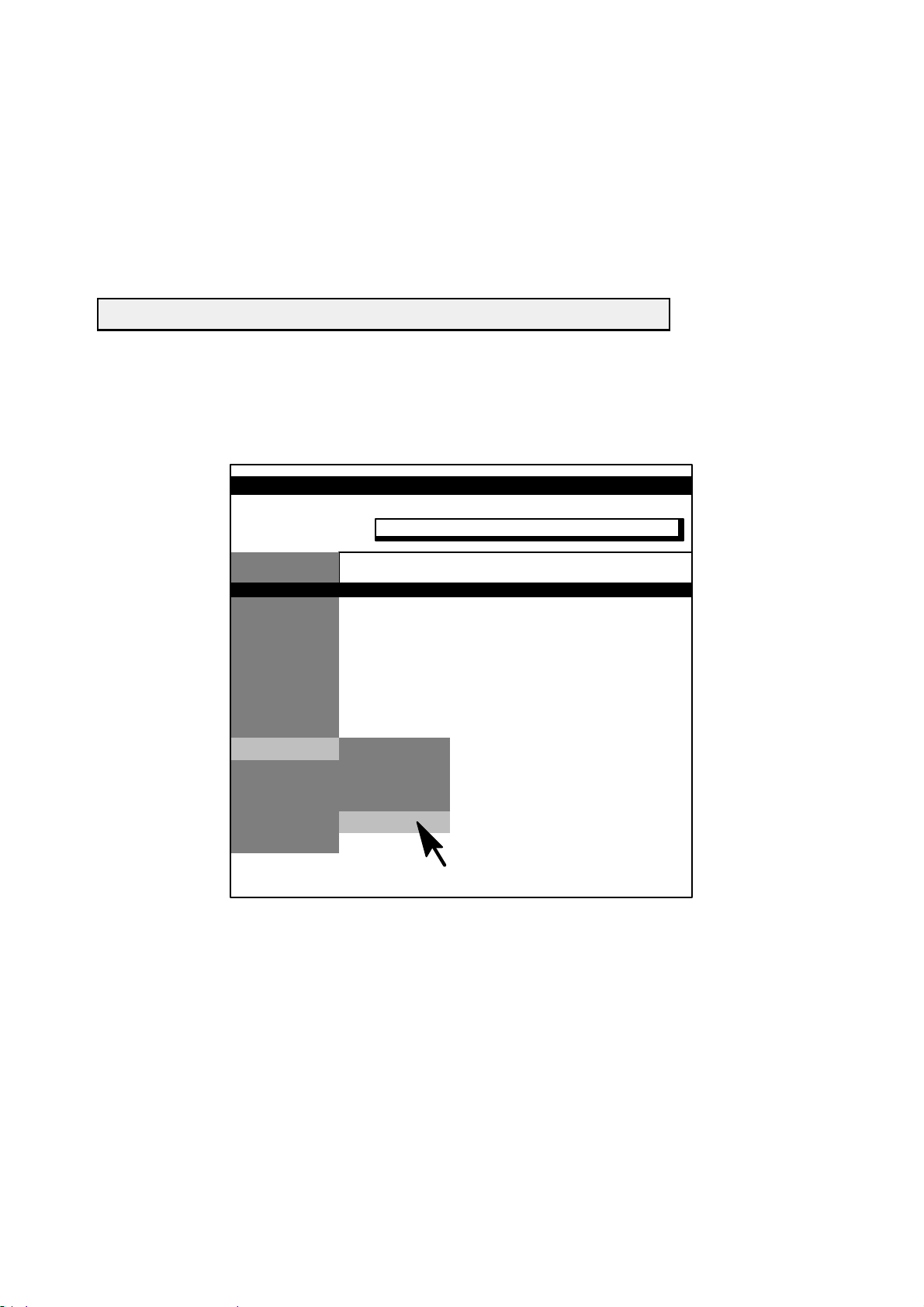
OPTIMUS C
FAULT FINDING
4.2. Operation
For installation of generator firmware and newest service tools see ”REPLACEMENT” chapter ”Exchange of
firmware ...”.
S Call the program with <xrgscope> or with <xrgscope lcd> for PCs with LCD screen.
S Enter your password.
The following menu line appears:
File OPTIMUS C Select Unit Options Help
Current data files, for instance, for online help, tube types, APR programming are available in the PHILIPS--Intranet.
Use path: http://technet.best.ms.philips.com/ and pull down menu as shown below.
PMS TechNet
PHILIPS
Insight Medical Systems
...
...
...
...
...
...
XRAY GENERATORS ...
...
...
...
...
...
DOWNLOAD
http://technet.best.ms.philips.com/
412H01
OPTIMUS C (a/02.1) 3--3
OPTIMUS_C_3_a021
E 2002 Philips Medizin Systeme
AlL RIGHTS RESERVED
Page 71

4.3. Menu structure
OPTIMUS
Program
Date and Time
Mains Data
Tubes
Tube 1 ... 3 (Tube 2 and 3 not applicable)
Tube Limits
Capacitance Tube Connection
Tube Operating Modes
Disable Tube
Dose Rate Control
AMPLIMAT (Chamber 3 ... 5 not applicable)
Image Intensifier [ ]
Fault Exposure Detection
CONT
Application Limits
X-Mode Limits
THORAVISION Limits (not applicable)
Overload dependent Limits [ ]
OPTIMUS CFAULT FINDING
Tube1...3DataSet
Tube 1 ... 3 Speed Selection
Sensitivity 1 + 2
Chamber 1 + 2
Data Set 1 ... 5 [ ] Data Set changes / Input ok
AEC
TDC
[]=A hardware key is required
E 2002 Philips Medizin Systeme
AlL RIGHTS RESERVED
OPTIMUS C(a/02.1)3--4
OPTIMUS_C_3_a021
Page 72

OPTIMUS C
Adjust
FAULT FINDING
Tube Adaptation
CAN Auto Configuration
Area Exposure Product (not applicable)
Specific Yield of Tubes
Specific Yield of Tubes 1 ... 3
Add Filter Correction T ables
2mmAl
1mmAl+0.1mmCU
1mmAl+0.2mmCU
Wedge Filter Correction Table
Wedge 1
Wedge 2
Finger Wedge
Dose Rate Control [ ]
TDC AMPLIMAT (Do not change the values without order from DMC Hamburg!)
Amplification Gain
TDC
CONT
CONT kV mA manual
Boost Adaptation [ ]
Accept
Backup [ ]
CU Complete
Restore [ ]
CU Complete
Inspect
Tube 1 Statistic
Show Tube Statistic
Reset Tube Statistic [ ]
Tube 2 ... 3 Statistic (Tube 2 and 3 not applicable)
Show Tube Statistic
Reset Tube Statistic [ ]
Generator Statistic
Type of Tube 1
Type of Tube 2 ... 3 (Tube 2 and 3 not applicable)
OPTIMUS C (a/02.1) 3--5
OPTIMUS_C_3_a021
E 2002 Philips Medizin Systeme
AlL RIGHTS RESERVED
Page 73

Faultfind []
Power ON Results
Options
Internal CAN Configuration
SW/HW-Versions
Logging Table
Error Log
X-Ray Log
CU Trace
OPTIMUS CFAULT FINDING
Error Log Index
Select Error Detail
Error Log Detail
---> Error Detail of CU
Error Info
Program Trace
---> Error Detail of kV
Error Info
Error Trace
Error HW Set Values
Error Read HW Values
Error Specific Information
---> Error Detail of mA
Error Info
Actual Status
Status Trace
HW Set Values
Read HW Values
Specific Information
Error Log Clear
Tube Temperature Supervision Logging
Tube Temperature Supervision Temperature Log
Tube Temperature Supervision Load Log
Tube Temperature Supervision Error Log
Dose Rate Control Logging
Read Actual Status
None Automatic Technique Calculation
AEC
AEC Calculation
AEC Trace
TDC
TDC Calculation
TDC Trace
CONT
CONT Calculation Start Value
CONT Calculation Curve
CONT Trace
Quit
E 2002 Philips Medizin Systeme
AlL RIGHTS RESERVED
OPTIMUS C(a/02.1)3--6
OPTIMUS_C_3_a021
Page 74

OPTIMUS C
FU-kV []
Adjust
IGBT Pulse Width Correction
Faultfind
Power ON Results
Logging Tables
Functional Test
Monitoring
Quit
FAULT FINDING
Read Configuration
Read Trace
Read Error (Only at current error with contents)
Error: Info
Error: Trace
Error: HW Set Values
Error: Read HW Values
Error: Specific Information
Test Watchdog
Test DAC-ADC
Test Converter
Switch Error Handling
Measure Temperatures
kV Measurements
Converter Measurements
Read8BitPort
Read 16 Bit Port
Read Memory
OPTIMUS C (a/02.1) 3--7
OPTIMUS_C_3_a021
E 2002 Philips Medizin Systeme
AlL RIGHTS RESERVED
Page 75

FU-mA []
Program
Read Focus Limits
Faultfind
Logging Tables
Functional Tests
Monitoring
Read I
Adaptation Results
Read Actual Status
Read Status Trace
Read Error (Only at current error with contents)
Error: Info
Error: Actual Status
Error: Status Trace
Error: HW Set Values
Error: Read HW Values
Error: Specific Information
Test Watchdog
Read I
Read I
Nominal
f
Actual
f
Read Intermed Circuit Voltage
Read I
Measurement Trace
e
Read8BitPort
Read 16 Bit Port
Read Memory
Corrections
e
Select Adaptation Table for Reading
Read Previously Selected Adaptation Table
OPTIMUS CFAULT FINDING
Quit
E 2002 Philips Medizin Systeme
AlL RIGHTS RESERVED
OPTIMUS C(a/02.1)3--8
OPTIMUS_C_3_a021
Page 76

OPTIMUS C
FAULT FINDING
4.4. Saving data on disk and restoring data
All configuration data and logging tables are stored in battery-buffered CMOS areas of the CU board.
Therefore, these data have to be saved on disk as a backup.
In case data get lost they can easily be restored in the CMOS areas after the error source has been eliminated.
Note
In case of mailing CU complete download files or any other xxx.tdl files use a zipped file format.
These files are ASCII files which might be destroyed while being mailed.
4.4.1. Saving of data
S Select menu:
ACCEPT/ BACKUP/ CU COMPLETE
S Store the data on floppy disk ”Generator configuration data“ found in the service documentation:
Default file name: cubackup.tdl
Recommended file name: s/n of the generator, e.g. 016012.tdl
File size: approx. 500--700kB
Transfer time: approx. 8min.
S Recommendation:
Additionally save the programmings for the film/screen combinations via the menu:
PROGRAM/ DOSE RATE CONTROL/ AMPLIMAT/ CHAMBER 1 +2/ DATA SET 1 ... 5 (manual processing)
Store them with the SAVE function <F3>--key on floppy disk.
Recommended file name: drc##.tdl ## = chamber and data set number
4.4.2. Restoring of data
S Select menu:
ACCEPT/ RESTORE/ CU COMPLETE
S Restore the data from floppy disk.
Transfer time approx. 15min ... 50min.
S Reset the generator.
S Program date and time.
Most of the programmings and logging tables can also be stored via the SAVE function <F3>--key of XRGSCOPE.
Some programmings can be restored via the LOAD-function <F4>--key.
S For service use, only keep the latest version of the backup.
Note
Never use a complete backup for a different generator, only if the hardware, firmware and option configuration are
identical.
OPTIMUS C (a/02.1) 3--9
OPTIMUS_C_3_a021
E 2002 Philips Medizin Systeme
AlL RIGHTS RESERVED
Page 77

5. Initialization phase of the generator
Start-up sequence
Switch ON of the generator.
|
V
Pulling-up of ENK2.
|
V
Selftest of ...
| ... central unit EZ139
| ... kV control EZ130 ------> voltage E is measured in the D.C. intermediate circuit
| ... mA control EZ119
| ... basic interface EZ150
| ... rotor control EY
OPTIMUS CFAULT FINDING
|
| Indicating device: The red status LED of the associated printed-circuit board or assembly is illuminated.
|
V
After successful selftest the status LEDs blink.
|
V
The central unit establishes connection to each functional unit via the CAN bus.
|
| Indicating device: The red status LED of the associated printed-circuit board or assembly grows dark.
|
V
ENK1 is switched ON.
|
V
The generator is internally ready.
|
V
The external ready circuits are checked ------> unit ready, door contact closed, thermal contact of the tube
| closed, tube not overloaded
|
V
The green READY lamp in the operating desk is illuminated.===>
E 2002 Philips Medizin Systeme
AlL RIGHTS RESERVED
The generator is in the READY state.
OPTIMUS C(a/02.1)3--10
OPTIMUS_C_3_a021
Page 78

OPTIMUS C
6. Switch ON problems
6.1. Switch ON not possible
See drawings: Z1--2.x
Z2-- 2.x.y
FAULT FINDING
H1 on PCB EN100 is
not illuminated
Error sources: -- ENF1 was released.
For fault finding look in the error buffer.
-- ENF1 is not switched ON.
-- Mains voltage, especially phase L3, is not present.
-- ENF2 was released.
Check: Low-voltage supply
Filament circuit
Tube extension
Rotor control
External current consumers
-- ENF2 is not switched ON.
-- PCB EN100 or its connections are not okay.
H1 on PCB EN100 is
illuminated
Error sources: -- The emergency--OFF circuit is open.
-- The operating desk is not connected.
6.2. No start up
Error sources: -- EN100 V1 is defective.
The generator receives a continuous reset via signalbus: reset sw/.
All red LEDs of the generator are illuminated.
Also see Z1--2.1.
-- No boot PROM present: EZ139 D3 (see 5Z--1).
-- Flash PROMs EZ139 D4/D5 not correctly loaded.
OPTIMUS C (a/02.1) 3--11
OPTIMUS_C_3_a021
E 2002 Philips Medizin Systeme
AlL RIGHTS RESERVED
Page 79

OPTIMUS CFAULT FINDING
7. Error numbers
7.1. Error classification
Errors:
-- Errors are indicated by 4 digits.
-- The first two digits indicate the Functional Unit FU reporting the error.
Example:
00xx = CU--functional unit is concerned
02xx = kV--functional unit is concerned
03xx = mA--functional unit is concerned
-- The last two digits indicate the error symptom.
Displayed errors (ERROR and FATAL ERROR):
-- These errors are indicated on the display of the operating desk for the customer.
Not all fatal errors come up on desk, use PC.
-- The customer must call the service.
The customer can inform the service about the respective error number and the service can order the spare parts
needed at an early stage of the maintenance procedure.
Not displayed errors (WARNING):
-- These errors are not relevant for the customer.
-- In case an error of this category occurs frequently within a certain period of time, a displayed error can be
generated.
Note
No WARNINGs, but only ERRORs are displayed on the COCKPIT control desk.
7.2. Error list
Sources of error codes indicated in the first two digits decimally (hexadecimally):
Error code dec (hex) FU (Function Unit) Description
00xx CU -- central unit EZ139
01xx FU_DRC -- dose rate control, control physically located on CU EZ139
-- parts of basic interface FU_CIE EZ150 also involved
(Amplimat)
-- FU_DRC also handles fluoro kV control EZ130
02xx FU_kV -- kV control EZ130
03xx FU_mA_a -- 1stmA control EZ119
-- handles 2 filaments
07xx FU_CIE -- central interface extension EZ150 basic interface
10xx (0Axx) FU_RC_a -- 1strotor control high speed EY100
E 2002 Philips Medizin Systeme
AlL RIGHTS RESERVED
OPTIMUS C(a/02.1)3--12
OPTIMUS_C_3_a021
Page 80

OPTIMUS C
FAULT FINDING
Error classes: FATAL ERROR, ERROR, WARNING
1. Errors as they occur in the error trace, XRGSCOPE and on the COCKPIT control desk, sorted by
alphanumerical code.
Error
Code
1
Error
Code
Error
2
Class
Error Text FU
00B0 6106648 ERROR CPU: Error in application data service interface CU
00B9 6106657 ERROR AD: Message from unknown function unit (FU) CU
00BP 6106680 ERROR AD: Unknown message from system controller CU
00BZ WARNING AD: Select mode of an unused buffer CU
00CB WARNING CONF: Received IIM #1#2H unknown CU
00CC WARNING CAN: Frame--repeat--counter overflow (IIM #1#2H) CU
00CD WARNING CAN: FU #1H not addressable CU
00CE WARNING CAN: rx--signal conflict (FU #1H) CU
00CF WARNING CAN: No RTR from FU #1H CU
00CG WARNING CPU: Domain tx response Mailbox type wrong CU
00CH WARNING CPU: Invalid tbdor--Parameter FU_type CU
00CJ WARNING CAN: Auto configuration successful (#1H) CU
00CK WARNING CAN: Auto configuration without success (#1H) CU
00CL WARNING CAN: FU #1H not addressable CU
00CM WARNING CAN: FU #1H sent event and did not answer RTR CU
00CP WARNING CAN: Max FU count exceeded CU
00CX WARNING CAN: Last--only--repeat--counter overflow (IIM #1#2H) CU
00DA 6106865 ERROR
No CPU--Access to CAN--chip CU
WARNING
00DD WARNING CAN--chip DPRAM check failed CU
00DE 6106869 ERROR
Unexpected CAN--chip int--pointer CU
WARNING
00DG WARNING CAN--chip error--active after passive #1H CU
00DH WARNING CAN--chip state error--passive #1H CU
00DI 6106873 ERROR CAN--chip state bus--OFF #1H CU
00DL 6106876 ERROR Unexpected CAN--chip interrupt CU
00DM WARNING CAN: Frame error (code #1H) CU
00E0 6106948 ERROR iRMX exception #2#1H occurred. CU
00FA WARNING CPU: CAL(CS)--Errorcode: #2#1H CU
00FB WARNING CPU: CS: Fast Domain Error CU
00G0 WARNING Variable in case statement has undefined value CU
1) As it occurs in the error log and within XRGSCOPE.
2) As it occurs on the COCKPIT desk.
OPTIMUS C (a/02.1) 3--13
OPTIMUS_C_3_a021
E 2002 Philips Medizin Systeme
AlL RIGHTS RESERVED
Page 81

OPTIMUS CFAULT FINDING
Error
Code
1
Error
Code
Error
2
Class
Error Text FU
00G1 6107149 ERROR Condition_code <> OK after CALL to send CU
00G2 WARNING Condition_code <> OK after CALL to init CU
00I2 WARNING No interrupt reason on sig--bus CU
00I3 WARNING No interrupt reason on XS--bus CU
00I4 6107352 ERROR OneFUhasaWD--error CU
00J1 6107449 ERROR DI: unknown IIM #1H CU
00J2 6107450 ERROR DI: rx LWDR param out of range FS= #1H PID= #2H CU
00J3 6107451 ERROR DI: rx LWDR message corrupted FS= #1H PID= #2H CU
00J4 6107452 ERROR DI: Internal table lookup failed FS= #1H PID= #2H CU
00J5 WARNING DI: tx LWDR param out of range FS= #1H PID= #2H CU
00J6 6107454 ERROR DI: tx L WDR param error FS= #1H PID= #2H ER= #3H CU
00J7 6107455 ERROR DI: LWDR message creation failed CU
00J8 WARNING DI: Unknown X--ray mode. No run data provided CU
00J9 WARNING DI: Message from suspended device ignored CU
00JA WARNING DI: No interface version received, message ignored CU
00JB 6107466 ERROR DI: Unknown LWDR message received FS= #1H CU
00JC 6107467 ERROR DI: tx LWDR message size invalid FS= #1H CU
00L1 6107649 ERROR GC: Checksum error CU
00L2 6107650 ERROR GC: Data access error CU
00L3 6107651 ERROR GC: Limit data error CU
00L4 6107652 ERROR GC: Limits inconsistent CU
00L5 6107653 ERROR GC: Calculation error CU
00L6 6107654 ERROR GC: Function not implemented CU
00M0 6107748 ERROR Unable to initialize FU(s) #1H, #2H, #3H, #4H, #5H, #6H CU
00M1 6107749 ERROR Configuration key is missing or defective CU
00M3 6107751 ERROR No response at all from FU(s) #1H, #2H, #3H, #4H, #5H, #6H CU
00M4 6107752 ERROR Function value from SE out of range CU
00M5 6107753 ERROR Procedure index from SE out of range CU
00MA WARNING Limit for allocated memory exceeded CU
00MB WARNING Limit for available memory exceeded CU
00MC WARNING Limit for borrowed memory exceeded CU
00MD WARNING Allocated memory is increasing CU
1) As it occurs in the error log and within XRGSCOPE.
2) As it occurs on the COCKPIT desk.
OPTIMUS C(a/02.1)3--14
E 2002 Philips Medizin Systeme
AlL RIGHTS RESERVED
OPTIMUS_C_3_a021
Page 82

OPTIMUS C
FAULT FINDING
Error
Code
1
Error
Code
Error
2
Class
Error Text FU
00ME WARNING Available memory is decreasing CU
00MF WARNING Borrowed memory is increasing CU
00MG WARNING NVRAM: Main control, NV checksum error CU
00MH 6107772 ERROR Job incorrectly identified CU
00PA WARNING CPU: IIM/MSC number unknown CU
00PB WARNING CPU: Technique mode unknown CU
00PC WARNING CPU: V alue limit overflow CU
00PD 6108068 ERROR PC comm.: Unknown TDL proc id CU
00PE WARNING NVRAM: DRC NV checksum error CU
00PF WARNING CPU: Equal kV--sets from CU comes twice CU
00PG WARNING CPU: kV sequence does not increase CU
00PH WARNING CPU: EDL is not possible, min_mA limit CU
00PI WARNING CPU: DCALC Dr_curve has only one element CU
00PJ WARNING CPU: DCALC Dr_curve has strange values CU
00PK WARNING CPU: Equal kV--sets from CU with equal mA CU
00PL WARNING CPU: Dose digits disturbance CU
00S* SERVICE PC comm.: Service access trace CU
00S? 6108363 ERROR PC comm.: Unexpected error CU
00S0 6108348 ERROR PC comm.: Tube programming error CU
00SA 6108365 ERROR PC comm.: Not enough space at destination segment CU
00SC 6108367 ERROR PC comm.: Value too large CU
00SD 6108368 ERROR PC comm.: Terminator not found CU
00SE 6108369 ERROR PC comm.: Error in description CU
00SF 6108370 ERROR PC comm.: Item type unknown CU
00SG 6108371 ERROR PC comm.: Internal type unknown CU
00SH 6108372 ERROR PC comm.: Value negative CU
00SJ 6108374 ERROR PC comm.: Syntax wrong CU
00SK 6108375 ERROR PC comm.: String too long CU
00SL WARNING PC comm.: String truncated CU
00SM WARNING PC comm.: TDL segment overflow CU
1) As it occurs in the error log and within XRGSCOPE.
2) As it occurs on the COCKPIT desk.
OPTIMUS C (a/02.1) 3--15
OPTIMUS_C_3_a021
E 2002 Philips Medizin Systeme
AlL RIGHTS RESERVED
Page 83

OPTIMUS CFAULT FINDING
Error
Code
1
Error
Code
Error
2
Class
Error Text FU
00SN 6108378 ERROR PC comm.: FU reference table full CU
00SO 6108379 ERROR PC comm.: Node ID unknown CU
00SP 6108380 ERROR PC comm.: FU code unknown CU
00SQ 6108381 ERROR PC comm.: Syntax error in node ID CU
00SR WARNING PC comm.: No node ID found CU
00SS 6108383 ERROR PC comm.: Request not performed CU
00ST 6108384 ERROR PC comm.: RMX error CU
00SU WARNING PC comm.: Enumeration element not found CU
00SV 6108386 ERROR PC comm.: Mail corrupted CU
00SW 6108387 ERROR PC comm.: Procedure ID unknown CU
00SX 6108388 ERROR PC comm.: FU mA incompatible CU
00SY 6108389 ERROR PC comm.: FU Off request failed CU
00SZ 6108390 ERROR PC comm.: Wrong response CU
00T? 6108463 ERROR TTS: Unexpected error CU
00TA 6108465 ERROR TTS: Received message unknown CU
00TB 6108466 ERROR TTS: Tube supervision error from FU kV CU
00TC 6108467 ERROR TTS: Internal TTS error CU
00TD 6108468 ERROR TTS: Tube number unknown CU
00TE 6108469 ERROR TTS: NVRAM checksum error CU
00TF 6108470 ERROR TTS: NVRAM unavailable CU
00TG 6108471 ERROR TTS: Tube overheated CU
00TH WARNING TTS: Load data supply inconsistent CU
00X0 6108848 ERROR CPU: Wrong timer id CU
00X1 6108849 ERROR CPU: Wrong timer mode CU
00X2 6108850 ERROR CPU: Wrong message type CU
00X3 WARNING CPU: DWORD does not fit into BYTE3 CU
00X4 6108852 ERROR
Timeout of X--ray backup timer CU
WARNING
00X5 WARNING Timeout of X--ray rotation timer CU
00X6 WARNING Timeout setting FUs, response missing CU
00X7 WARNING CPU curve token is NO_TOKEN CU
1) As it occurs in the error log and within XRGSCOPE.
2) As it occurs on the COCKPIT desk.
OPTIMUS C(a/02.1)3--16
E 2002 Philips Medizin Systeme
AlL RIGHTS RESERVED
OPTIMUS_C_3_a021
Page 84

OPTIMUS C
FAULT FINDING
Error
Code
1
Error
Code
Error
2
Class
Error Text FU
00XB WARNING NVRAM tube data rotation invalid CU
00XC WARNING NVRAM watch dog invalid CU
00XD WARNING NVRAM confi table invalid CU
00XE WARNING NVRAM test data invalid CU
00XF WARNING NVRAM RoCo data invalid CU
00XI 6108873 ERROR Init with FU--RoCo not OK CU
00XJ 6108874 ERROR
Exposure time too short CU
WARNING
00XK WARNING CPU: FUmA refuses set data CU
00XL WARNING NVRAM tube yield table invalid CU
00XM WARNING NVRAM add filter corr table invalid CU
00XN WARNING NVRAM wedge filter corr table invalid CU
00XO 6108879 ERROR Exposure time too long CU
00XP WARNING Exposure time too long CU
00XQ WARNING NVRAM tube statistic data invalid CU
00XR WARNING CU
00XS WARNING Tube no in CU and FUkV different CU
00XT WARNING Rotation in CU and FURoCo FUCIE diff. CU
00XU 6108885 ERROR Transition endless loop CU
00XV WARNING NVRAM HW test flags invalid CU
00XW 6108887 ERROR EN_X active in startup CU
00XX 6108888 ERROR RD_PR_X stays active after prep CU
02AB WARNING Procedure called with wrong parameter FU_kV
02AC 6126567 ERROR Wrong index for table access FU_kV
02AD 6126568 ERROR Wrong do case entry FU_kV
02AE WARNING Unknown IIM received FU_kV
02AF WARNING IIM parameter out of range FU_kV
02CA WARNING Error in CASE selector FU_kV
02CB WARNING A CAN message with wrong IIM--no (no recipient defined) received FU_kV
1) As it occurs in the error log and within XRGSCOPE.
2) As it occurs on the COCKPIT desk.
OPTIMUS C (a/02.1) 3--17
OPTIMUS_C_3_a021
E 2002 Philips Medizin Systeme
AlL RIGHTS RESERVED
Page 85

OPTIMUS CFAULT FINDING
Error
Code
1
Error
Code
Error
2
Class
Error Text FU
02CC WARNING Multiple reception of the same CAN frame (transmitter ill) FU_kV
02CE WARNING Unexpected signal value in CAN rx task FU_kV
02CF WARNING CAN bus timeout while domain transmission FU_kV
02CG WARNING Token of CAN response mailbox is not a mailbox token FU_kV
02CX WARNING Multiple rx of the same CAN last/only frame (transmitter ill) FU_kV
02CY WARNING Aborted CAN domain receive (because of timeout or wrong signal) FU_kV
02CZ WARNING Unexpected CAN domain frame received (outside IIM--reception) FU_kV
02DA WARNING No CPU access to the CAN controller FU_kV
02DB WARNING Reset or release of the CAN controller was not acknowledged FU_kV
02DD WARNING Check of the DPRAM of the CAN controller failed FU_kV
02DE WARNING Unexpected interrupt pointer in the CAN controller FU_kV
02DF WARNING CAN controller state undefined FU_kV
02DG WARNING CAN controller state ERROR ACTIVE after ERROR PASSIVE FU_kV
02DH WARNING CAN controller state ERROR PASSIVE FU_kV
02DI WARNING CAN controller state BUS OFF FU_kV
02DJ WARNING CAN controller state DPRAM ERROR FU_kV
02DK WARNING CAN controller state DPRAM ERROR and ERROR PASSIVE FU_kV
02EA 6126965 ERROR Interrupt 0: Divide by zero FU_kV
02EB 6126966 ERROR Interrupt 1: Single step FU_kV
02EC 6126967 ERROR Interrupt 2: NMI FU_kV
02ED 6126968 ERROR Interrupt 3: Breakpoint FU_kV
02EE 6126969 ERROR Interrupt 4: Overflow exception FU_kV
02EF 6126970 ERROR Interrupt 5: Array bounds exception FU_kV
02EG 6126971 ERROR Interrupt 6: Unused opcode FU_kV
02EH 6126972 ERROR Interrupt 7: ESC opcode FU_kV
02EI 6126973 ERROR CAN connection to CU lost FU_kV
02GA WARNING Interpolation not possible FU_kV
02HA WARNING kV nominal value out of range FU_kV
02HB 6127266 ERROR kV nominal value out of range FU_kV
02HC WARNING Z nominal value out of range FU_kV
1) As it occurs in the error log and within XRGSCOPE.
2) As it occurs on the COCKPIT desk.
E 2002 Philips Medizin Systeme
AlL RIGHTS RESERVED
OPTIMUS C(a/02.1)3--18
OPTIMUS_C_3_a021
Page 86

OPTIMUS C
FAULT FINDING
Error
Code
1
Error
Code
Error
2
Class
Error Text FU
02HD 6127268 ERROR Z nominal value out of range FU_kV
02HE WARNING kV value during standby too large FU_kV
02HF 6127270 ERROR kV value during standby too large FU_kV
02HG WARNING kV actual value out of range FU_kV
02HH 6127272 ERROR kV actual value out of range FU_kV
02HI WARNING E value during standby out of range FU_kV
02HJ 6127274 ERROR E value during standby out of range FU_kV
02HK WARNING E value during high tension out of range FU_kV
02HL 6127276 ERROR E value during high tension out of range FU_kV
02HM WARNING Converter 1 temperature out of range FU_kV
02HN 6127278 ERROR Converter 1 temperature out of range FU_kV
02HO WARNING Converter 2 temperature out of range FU_kV
02HP 6127280 ERROR Converter 2 temperature out of range FU_kV
02HQ WARNING High voltage tank temperature out of range FU_kV
02HR 6127282 ERROR High voltage tank temperature out of range FU_kV
02HS WARNING Divider test cathode out of range FU_kV
02HT 6127284 ERROR Divider test cathode out of range FU_kV
02HU WARNING Divider test anode out of range FU_kV
02HV 6127286 ERROR Divider test anode out of range FU_kV
02HW WARNING kV asymmetrical FU_kV
02HX 6127288 ERROR kV asymmetrical FU_kV
02MA 6127765 ERROR State request not accepted because of grid mode FU_kV
02MB 6127766 ERROR State request not accepted because of error state FU_kV
02MC WARNING State requested by CU unknown FU_kV
02OA 6127965 ERROR RMX error: Timeout FU_kV
02OB 6127966 ERROR RMX error: Memory FU_kV
02OC 6127967 ERROR RMX error: Busy FU_kV
02OE 6127969 ERROR RMX error: Limit FU_kV
02OF 6127970 ERROR RMX error: Context FU_kV
02OG 6127971 ERROR RMX error: Exist FU_kV
02OH 6127972 ERROR RMX error: State FU_kV
1) As it occurs in the error log and within XRGSCOPE.
2) As it occurs on the COCKPIT desk.
OPTIMUS C (a/02.1) 3--19
OPTIMUS_C_3_a021
E 2002 Philips Medizin Systeme
AlL RIGHTS RESERVED
Page 87

OPTIMUS CFAULT FINDING
Error
Code
1
Error
Code
Error
2
Class
Error Text FU
02OI 6127973 ERROR RMX error: Not configured FU_kV
02OJ 6127974 ERROR RMX error: Interrupt saturation FU_kV
02OK 6127975 ERROR RMX error: Interrupt overflow FU_kV
02OL 6127976 ERROR RMX error: Transmission FU_kV
02OM 6127977 ERROR RMX error: Divide by zero FU_kV
02ON 6127978 ERROR RMX error: Overflow FU_kV
02OO 6127979 ERROR RMX error: Type FU_kV
02OP 6127980 ERROR RMX error: Parameter FU_kV
02OQ 6127981 ERROR RMX error: Bad call FU_kV
02OR 6127982 ERROR RMX error: Array bound FU_kV
02OS 6127983 ERROR RMX error: NDP error FU_kV
02OT 6127984 ERROR RMX error: Illegal opcode FU_kV
02OU 6127985 ERROR RMX error: Emulator trap FU_kV
02OV 6127986 ERROR RMX error: Interrupt table limit FU_kV
02OW 6127987 ERROR RMX error: CPU xfer data limit FU_kV
02OX 6127988 ERROR RMX error: Wrap around FU_kV
02OY 6127989 ERROR RMX error: Check exception FU_kV
02OZ 6127990 ERROR RMX error: Unknown FU_kV
02RA WARNING Grid mode changeover requested during preparation FU_kV
02RB WARNING Tube switch requested during preparation FU_kV
02RC WARNING Requested P out of range FU_kV
02SA WARNING Not enough space at the destination FU_kV
02SB WARNING Base out of range FU_kV
02SC WARNING PC comm..: Value too large FU_kV
02SD WARNING Terminator not found FU_kV
02SE WARNING PC comm.: Error in description FU_kV
02SF WARNING PC comm.: Item type unknown FU_kV
02SG WARNING PC comm.: Internal type unknown FU_kV
02SH WARNING PC comm.: Value negative FU_kV
02SI WARNING PC comm.: No space at dest. buffer FU_kV
1) As it occurs in the error log and within XRGSCOPE.
2) As it occurs on the COCKPIT desk.
E 2002 Philips Medizin Systeme
AlL RIGHTS RESERVED
OPTIMUS C(a/02.1)3--20
OPTIMUS_C_3_a021
Page 88

OPTIMUS C
FAULT FINDING
Error
Code
1
Error
Code
Error
2
Class
Error Text FU
02SJ WARNING PC comm.: Syntax wrong FU_kV
02SK WARNING PC comm.: String too long FU_kV
02SL WARNING PC comm.: String truncated FU_kV
02SO WARNING PC comm.: Unknown table ID received FU_kV
02SP WARNING PC comm.: Access level to low FU_kV
02SQ WARNING PC comm.: Unknown action requested FU_kV
02SR WARNING PC comm.: Routing or message corrupt FU_kV
02SS WARNING Source buffer to small for incoming message FU_kV
02ST WARNING CAN buffer to small for outgoing message FU_kV
02SU WARNING PC comm.: Access. level is N_A FU_kV
02UA 6128565 ERROR HW configuration identifier wrong FU_kV
02UB WARNING Set up request received during preparation FU_kV
02WA WARNING Wrong tube selected FU_kV
02WB 6128766 ERROR Wrong tube selected FU_kV
02WC WARNING EN X C signal faulty FU_kV
02WD 6128768 ERROR EN X C signal faulty FU_kV
02WE WARNING Wrong grid mode selected FU_kV
02WF 6128770 ERROR Wrong grid mode selected FU_kV
02WG W ARNING Tube arcing detected FU_kV
02WH 6128772 ERROR Tube arcing detected FU_kV
02WI WARNING kV over voltage detected FU_kV
02WJ 6128774 ERROR kV over voltage detected FU_kV
02WK WARNING Measuring not stable FU_kV
02WL 6128776 ERROR Tube supervision error FU_kV
02WM 6128777 ERROR Tube supervision error FU_kV
03AA WARNING Internal parameter error FU_mA
03AB WARNING Wrong parameter from CU FU_mA
03AC WARNING Ie--regulation active on two filaments FU_mA
03AI WARNING Wrong IIM received FU_mA
03BA WARNING Coordinates not monotonous FU_mA
03BB WARNING No measurement values for adap. found FU_mA
1) As it occurs in the error log and within XRGSCOPE.
2) As it occurs on the COCKPIT desk.
OPTIMUS C (a/02.1) 3--21
OPTIMUS_C_3_a021
E 2002 Philips Medizin Systeme
AlL RIGHTS RESERVED
Page 89

OPTIMUS CFAULT FINDING
Error
Code
1
Error
Code
Error
2
Class
Error Text FU
03CA WARNING Error in CASE selector FU_mA
03CB WARNING A CAN message with wrong IIM--no (no recipient defined) received FU_mA
03CC WARNING Multiple reception of the same CAN frame (transmitter ill) FU_mA
03CE WARNING Unexpected signal value in CAN rx task FU_mA
03CF WARNING CAN bus timeout while domain transmission FU_mA
03CG WARNING Token of CAN response mailbox is not a mailbox token FU_mA
03CX WARNING Multiple rx of the same CAN last/only frame (transmitter ill) FU_mA
03CY WARNING Aborted CAN domain receive (because of timeout or wrong signal) FU_mA
03CZ WARNING Unexpected CAN domain frame received (outside IIM--reception) FU_mA
03DA WARNING No CPU access to the CAN controller FU_mA
03DB WARNING Reset or release of the CAN controller was not acknowledged FU_mA
03DD WARNING Check of the DPRAM of the CAN controller failed FU_mA
03DE WARNING Unexpected interrupt pointer in the CAN controller FU_mA
03DF WARNING CAN controller state undefined FU_mA
03DG WARNING CAN controller state ERROR ACTIVE after ERROR PASSIVE FU_mA
03DH WARNING CAN controller state ERROR PASSIVE FU_mA
03DI WARNING CAN controller state BUS OFF FU_mA
03DJ WARNING CAN controller state DPRAM ERROR FU_mA
03DK WARNING CAN controller state DPRAM ERROR and ERROR PASSIVE FU_mA
03EA 6136965 ERROR CPU interrupt 0 FU_mA
03EB 6136966 ERROR CPU interrupt 1 FU_mA
03ED 6136968 ERROR CPU interrupt 3 FU_mA
03EE 6136969 ERROR CPU interrupt 4 FU_mA
03EF 6136970 ERROR CPU interrupt 5 FU_mA
03EG 6136971 ERROR CPU interrupt 6 FU_mA
03EH 6136972 ERROR CPU interrupt 7 FU_mA
03EI 6136973 ERROR CAN is unable to send an error to CU FU_mA
03FA WARNING NVRAM: Invalid checksum FU_mA
03FB WARNING NVRAM: Standby filament not found FU_mA
03FC 6137067 ERROR No NVRAM plugged in FU_mA
03FD WARNING NVRAM empty FU_mA
1) As it occurs in the error log and within XRGSCOPE.
2) As it occurs on the COCKPIT desk.
OPTIMUS C(a/02.1)3--22
E 2002 Philips Medizin Systeme
AlL RIGHTS RESERVED
OPTIMUS_C_3_a021
Page 90

OPTIMUS C
FAULT FINDING
Error
Code
1
Error
Code
Error
2
Class
Error Text FU
03GA 6137165 ERROR Limit error FU_mA
03GB WARNING Real math. error: Real underflow FU_mA
03GC WARNING Real math. error: Real overflow FU_mA
03GD WARNING Real math. error: Dword overflow FU_mA
03GE WARNING Real math. error: Integer overflow FU_mA
03GF WARNING Real math. error: Word overflow FU_mA
03GG WARNING Singular matrix FU_mA
03HA 6137265 ERROR Unknown hardware FU_mA
03HB 6137266 WARNING
Intermediate circuit voltage < 200V FU_mA
ERROR
03HF WARNING Undefined analog input channel FU_mA
03HG WARNING If--actual out of tolerance FU_mA
03HH 6137272 ERROR If setpoint to large FU_mA
03HI 6137273 ERROR If--actual out of tolerance FU_mA
03HJ 6137274 ERROR If--actual out of tolerance FU_mA
03HK WARNING If--nominal out of tolerance FU_mA
03HL 6137276 ERROR If--nominal out of tolerance FU_mA
03HM 6137277 ERROR If--nominal out of tolerance FU_mA
03HN 6137278 ERROR No retrigger received from CU FU_mA
03IA WARNING Adaptation can not be completed FU_mA
03IC WARNING No Ie--adaptation measurement values FU_mA
03ID WARNING Ie--adaptation values not evolvable FU_mA
03KA WARNING Condi.--X--Ray mode without mAs parameter FU_mA
03MA WARNING Undefined status FU_mA
03MB WARNING Status change not allowed FU_mA
03MC WARNING FU init data not expected FU_mA
03OA 6137965 ERROR RMX exception: E$TIME FU_mA
03OB 6137966 ERROR RMX exception: E$MEM FU_mA
03OC 6137967 ERROR RMX exception: E$BUSY FU_mA
03OD 6137968 ERROR RMX exception: E$LIMIT FU_mA
03OE 6137969 ERROR RMX exception: E$CONTEXT FU_mA
03OF 6137970 ERROR RMX exception: E$EXIST FU_mA
03OG 6137971 ERROR RMX exception: E$STA TE FU_mA
1) As it occurs in the error log and within XRGSCOPE.
2) As it occurs on the COCKPIT desk.
OPTIMUS C (a/02.1) 3--23
OPTIMUS_C_3_a021
E 2002 Philips Medizin Systeme
AlL RIGHTS RESERVED
Page 91

OPTIMUS CFAULT FINDING
Error
Code
1
Error
Code
Error
2
Class
Error Text FU
03OH 6137972 ERROR RMX exception: E$NOT$CONFIGURED FU_mA
03OI 6137973 ERROR RMX exception: E$INTERRUPT$SATURATION FU_mA
03OJ 6137974 ERROR RMX exception: E$INTERRUPT$OVERFLOW FU_mA
03OK 6137975 ERROR RMX exception: E$TRANSMISSION FU_mA
03OL 6137976 ERROR RMX exception: E$ZERO$DIVIDE FU_mA
03OM 6137977 ERROR RMX exception: E$OVERFLOW FU_mA
03ON 6137978 ERROR RMX exception: E$TYPE FU_mA
03OO 6137979 ERROR RMX exception: E$PARAM FU_mA
03OP 6137980 ERROR RMX exception: E$BAD$CALL FU_mA
03OQ 6137981 ERROR RMX exception: E$ARRAY$BOUND FU_mA
03OR 6137982 ERROR RMX exception: E$NDP$ERROR FU_mA
03OS 6137983 ERROR RMX exception: E$ILLEGAL$OPCODE FU_mA
03OT 6137984 ERROR RMX exception: E$EMULATOR$TRAP FU_mA
03OU 6137985 ERROR RMX exception: E$INTERRUPT$TABLE$LIMIT FU_mA
03OV 6137986 ERROR RMX exception: E$CPUXFER$DATA$LIMIT FU_mA
03OW 6137987 ERROR RMX exception: E$SEG$WRAP$AROUND FU_mA
03OX 6137988 ERROR RMX exception: E$CHECK$EXCEPTION FU_mA
03OY 6137989 ERROR Unknown RMX exception FU_mA
03PA 6138065 ERROR Ie zero measured FU_mA
03PB WARNING Ie out of tolerance FU_mA
03PC 6138067 ERROR Ie out of tolerance FU_mA
03PD WARNING Setpoint for Ie--regulation incorrect FU_mA
03PE 6138069 ERROR Emergency OFF, grid not closed! FU_mA
03PF 6138070 ERROR No kV discharged due to missing Ie FU_mA
03SC WARNING PC comm.: Value too large FU_mA
03SE WARNING PC comm.: Error in description FU_mA
03SF WARNING PC comm.: Item type unknown FU_mA
03SG WARNING PC comm.: Internal type unknown FU_mA
03SH WARNING PC comm.: Value negative FU_mA
03SI WARNING PC comm.: No space at dest. buffer FU_mA
03SJ WARNING PC comm.: Syntax wrong FU_mA
1) As it occurs in the error log and within XRGSCOPE.
2) As it occurs on the COCKPIT desk.
OPTIMUS C(a/02.1)3--24
E 2002 Philips Medizin Systeme
AlL RIGHTS RESERVED
OPTIMUS_C_3_a021
Page 92

OPTIMUS C
FAULT FINDING
Error
Code
1
Error
Code
Error
2
Class
Error Text FU
03SK WARNING PC comm.: String too long FU_mA
03SL WARNING PC comm.: String truncated FU_mA
03SO WARNING PC comm.: Unknown Table ID Received FU_mA
03SP WARNING PC comm.: Access Level to Low FU_mA
03SQ WARNING PC comm.: Unknown Action Requested FU_mA
03SR WARNING PC comm.: Routing or Message Corrupt FU_mA
03SU WARNING PC comm.: Access. level is N_A FU_mA
07CA 6176765 ERROR CAN: Case--selector error FU_CIE
07CB WARNING CAN: Invalid CAN ID %u FU_CIE
07CC 6176767 ERROR CAN: Frame rep. overflow IIM%u FU_CIE
07CD 6176768 ERROR CAN: No RTR from CU FU_CIE
07CE 6176769 ERROR CAN: rx signal conflict IIM%u FU_CIE
07CF 6176770 ERROR CAN: tx timeout FU_CIE
07CI WARNING CAN: IMPOSSIBLE ERROR FU_CIE
07CP WARNING CAN: CPU: PXerr %d %s(%d) FU_CIE
07CR WARNING CAN: CPU: message request fail FU_CIE
07CS WARNING CAN: CPU: message send error FU_CIE
07CY 6176789 ERROR CAN: rx abort IIM%u FU_CIE
07CZ WARNING CAN: Unexpected frame (IIM%u) FU_CIE
07DA 6176865 ERROR CAN: Chip access error FU_CIE
07DB 6176866 ERROR CAN: Chip reset error FU_CIE
07DC 6176867 ERROR CAN: Chip reset release error FU_CIE
07DE WARNING CAN: Illegal interrupt pointer FU_CIE
07DF 6176870 ERROR CAN: Chip state undefined FU_CIE
07DG WARNING CAN: Chip err act. after pass. FU_CIE
07DH WARNING CAN: Chip state error passive FU_CIE
07DI WARNING CAN: Chip state bus--OFF FU_CIE
07DJ 6176874 ERROR CAN: Chip DPRAM error FU_CIE
07DK WARNING CAN: Chip DPRAM error&passive FU_CIE
07DL WARNING CAN: Unexpected interrupt FU_CIE
1) As it occurs in the error log and within XRGSCOPE.
2) As it occurs on the COCKPIT desk.
OPTIMUS C (a/02.1) 3--25
OPTIMUS_C_3_a021
E 2002 Philips Medizin Systeme
AlL RIGHTS RESERVED
Page 93

OPTIMUS CFAULT FINDING
Error
Code
1
Error
Code
Error
2
Class
Error Text FU
07LA WARNING CV received IIM unknown FU_CIE
07LB WARNING RC stator number out of range FU_CIE
07LC WARNING RC stator not available FU_CIE
07LD 6177668 ERROR RC stator 1 readback failed FU_CIE
07LE 6177669 ERROR RC stator 2 readback failed FU_CIE
07LF 6177670 ERROR RC stator 3 readback failed FU_CIE
07LG WARNING RC speed value out of range FU_CIE
07LH 6177672 ERROR RC speed set timeout FU_CIE
07LI WARNING RC maximal stator load exceeded FU_CIE
07LJ 6177674 ERROR RC maximal rotation time exceeded FU_CIE
07LK WARNING AM amplimat chamber number out of range FU_CIE
07LL WARNING AM amplimat field number out of range FU_CIE
07LM WARNING AM amplimat delay value out of range FU_CIE
10CA 6156765 ERROR CAN: Case--selector error FU_RC
10CB WARNING CAN: Invalid CAN ID %u FU_RC
10CC 6156767 ERROR CAN: Frame rep. overflow IIM%u FU_RC
10CD 6156768 ERROR CAN: No RTR from CU FU_RC
10CE 6156769 ERROR CAN: rx signal conflict IIM%u FU_RC
10CF 6156770 ERROR CAN: tx timeout FU_RC
10CI WARNING CAN: IMPOSSIBLE ERROR FU_RC
10CP WARNING CAN: CPU: PXerr %d %s(%d) FU_RC
10CR WARNING CAN: CPU: message request fail FU_RC
10CS WARNING CAN: CPU: message send error FU_RC
10CY 6156789 ERROR CAN: rx abort IIM%u FU_RC
10CZ WARNING CAN: Unexpected frame (IIM%u) FU_RC
10DA 6156865 ERROR CAN: Chip access error FU_RC
10DB 6156866 ERROR CAN: Chip reset error FU_RC
10DC 6156867 ERROR CAN: Chip reset release error FU_RC
10DE WARNING CAN: Illegal interrupt pointer FU_RC
10DF 6156870 ERROR CAN: Chip state undefined FU_RC
10DG WARNING CAN: Chip err act. after pass. FU_RC
1) As it occurs in the error log and within XRGSCOPE.
2) As it occurs on the COCKPIT desk.
OPTIMUS C(a/02.1)3--26
E 2002 Philips Medizin Systeme
AlL RIGHTS RESERVED
OPTIMUS_C_3_a021
Page 94

OPTIMUS C
FAULT FINDING
Error
Code
1
Error
Code
Error
2
Class
Error Text FU
10DH WARNING CAN: Chip state error passive FU_RC
10DI WARNING CAN: Chip state bus--OFF FU_RC
10DJ 6156874 ERROR CAN: Chip DPRAM error FU_RC
10DK WARNING CAN: Chip DPRAM error & passive FU_RC
10DL WARNING CAN: Unexpected interrupt FU_RC
10FB 6157066 ERROR Short circuit detected FU_RC
10FT WARNING Overcurrent detected FU_RC
10IF WARNING Initialization failed FU_RC
10LA WARNING Acceleration count limit exceeded FU_RC
10LH 6157672 ERROR Phase current %u mA (>%u) FU_RC
10LL 6157676 ERROR Phase current %u mA (<%u) FU_RC
10LO 6157679 WARNING
Intermediate voltage %u V (>%u) FU_RC
ERROR
10L T 6157684 ERROR Temperature limit exceeded FU_RC
10LU 6157685 WARNING
Intermediate voltage %u V (<%u) FU_RC
ERROR
10LZ 6157690 ERROR T emperature sensor failure FU_RC
10OE WARNING CPU: PXROS error %d FU_RC
10OF WARNING CPU: PXROS error %d %s(%d) FU_RC
10RC 6158267 ERROR Rotation check failed FU_RC
10RI 6158273 ERROR Invalid rotation request: %u FU_RC
10RT 6158284 ERROR Rotation request timeout FU_RC
10TD 6158468 ERROR Invalid data for tube %u FU_RC
10TE 6158469 ERROR Stator %u hardware error FU_RC
10TF 6158470 ERROR Stator %u switching failed FU_RC
10TI 6158473 ERROR Invalid stator request: %u FU_RC
10TR 6158482 ERROR Stator change with rotating anode FU_RC
10UI WARNING Unknown message from CU: IIM %u FU_RC
10UM WARNING Unexpected message from CU: IIM %u FU_RC
10WT WARNING CPU: Watchdog timeout FU_RC
10XX WARNING IMPOSSIBLE ERROR FU_RC
1) As it occurs in the error log and within XRGSCOPE.
2) As it occurs on the COCKPIT desk.
OPTIMUS C (a/02.1) 3--27
OPTIMUS_C_3_a021
E 2002 Philips Medizin Systeme
AlL RIGHTS RESERVED
Page 95

OPTIMUS CFAULT FINDING
2. Errors as they occur on the COCKPIT control desk, in the error trace and in XRGSCOPE, sorted by
numerical code.
Error
Code
Error
3
Code
4
Error
Class
Error Text FU
6106648 00B0 ERROR CPU: Error in application data service interface CU
6106657 00B9 ERROR AD: Message from unknown function unit (FU) CU
6106680 00BP ERROR AD: Unknown message from system controller CU
6106865 00DA ERROR
No CPU--Access to CAN--chip CU
WARNING
6106869 00DE ERROR
Unexpected CAN--chip int--pointer CU
WARNING
6106873 00DI ERROR CAN--chip state bus--OFF #1H CU
6106876 00DL ERROR Unexpected CAN--chip interrupt CU
6106984 00E0 ERROR iRMX exception #2#1H occurred CU
6107149 00G1 ERROR Condition_code <> OK after CALL to send CU
6107352 00I4 ERROR OneFUhasaWD--error CU
6107449 00J1 ERROR DI: Unknown IIM #1H CU
6107450 00J2 ERROR DI: rx LWDR param out of range FS= #1H PID= #2H CU
6107451 00J3 ERROR DI: rx LWDR message corrupted FS= #1H PID= #2H CU
6107452 00J4 ERROR DI: Internal table lookup failed FS= #1H PID= #2H CU
6107454 00J6 ERROR DI: tx LWDR param error FS= #1H PID= #2H ER= #3H CU
6107455 00J7 ERROR DI: LWDR message creation failed CU
6107466 00JB ERROR DI: Unknown LWDR message received FS= #1H CU
6107467 00JC ERROR DI: tx LWDR message size invalid FS= #1H CU
6107649 00L1 ERROR GC: Checksum error CU
6107650 00L2 ERROR GC: Data access error CU
6107651 00L3 ERROR GC: Limit data error CU
6107652 00L4 ERROR GC: Limits inconsistent CU
6107653 00L5 ERROR GC: Calculation error CU
6107654 00L6 ERROR GC: Function not implemented CU
6107748 00M0 ERROR Unable to initialize FU(s) #1H, #2H, #3H, #4H, #5H, #6H CU
6107749 00M1 ERROR Configuration key is missing or defective CU
6107751 00M3 ERROR No response at all from FU(s) #1H, #2H, #3H, #4H, #5H, #6H CU
6107752 00M4 ERROR Function value from SE out of range CU
6107753 00M5 ERROR Procedure index from SE out of range CU
6107772 00MH ERROR Job incorrectly identified CU
3) As it occurs on the COCKPIT desk.
4) As it occurs in the error log and within XRGSCOPE.
OPTIMUS C(a/02.1)3--28
E 2002 Philips Medizin Systeme
AlL RIGHTS RESERVED
OPTIMUS_C_3_a021
Page 96

OPTIMUS C
FAULT FINDING
Error
Code
Error
3
Code
4
Error
Class
Error Text FU
6108068 00PD ERROR PC comm.: Unknown TDL proc id CU
6108348 00S0 ERROR PC comm.: Tube programming error CU
6108363 00S? ERROR PC comm.: Unexpected error CU
6108365 00SA ERROR PC comm.: Not enough space at destination segment CU
6108367 00SC ERROR PC comm.: Value too large CU
6108368 00SD ERROR PC comm.: Terminator not found CU
610836 00SE ERROR PC comm.: Error in description CU
6108370 00SF ERROR PC comm.: Item type unknown CU
6108371 00SG ERROR PC comm.: Internal type unknown CU
6108372 00SH ERROR PC comm.: Value negative CU
6108374 00SJ ERROR PC comm.: Syntax wrong CU
6108375 00SK ERROR PC comm.: String too long CU
6108378 00SN ERROR PC comm.: FU reference table full CU
6108379 00SO ERROR PC comm.: Node ID unknown CU
6108380 00SP ERROR PC comm.: FU code unknown CU
6108381 00SQ ERROR PC comm.: Syntax error in node ID CU
6108383 00SS ERROR PC comm.: Request not performed CU
6108384 00ST ERROR PC comm.: RMX error CU
6108386 00SV ERROR PC comm.: Mail corrupted CU
6108387 00SW ERROR PC comm.: Procedure ID unknown CU
6108388 00SX ERROR PC comm.: FU mA incompatible CU
6108389 00SY ERROR PC comm.: FU OFF request failed CU
6108390 00SZ ERROR PC comm.: Wrong response CU
6108463 00T? ERROR TTS: Unexpected Error CU
6108465 00TA ERROR TTS: Received message unknown CU
6108466 00TB ERROR TTS: Tube supervision error from FU kV CU
6108467 00TC ERROR TTS: Internal TTS error CU
6108468 00TD ERROR TTS: Tube number unknown CU
6108469 00TE ERROR TTS: NVRAM checksum error CU
6108470 00TF ERROR TTS: NVRAM unavailable CU
6108471 00TG ERROR TTS: Tube overheated CU
3) As it occurs on the COCKPIT desk.
4) As it occurs in the error log and within XRGSCOPE.
OPTIMUS C (a/02.1) 3--29
OPTIMUS_C_3_a021
E 2002 Philips Medizin Systeme
AlL RIGHTS RESERVED
Page 97

OPTIMUS CFAULT FINDING
Error
Code
Error
3
Code
4
Error
Class
Error Text FU
6108848 00X0 ERROR CPU: Wrong timer id CU
6108849 00X1 ERROR CPU: Wrong timer mode CU
6108850 00X2 ERROR CPU: Wrong message type CU
6108852 00X4 ERROR
Timeout of X--ray backup timer CU
WARNING
6108873 00XI ERROR Init with FU--RoCo not OK CU
6108874 00XJ ERROR
Exposure time too short CU
WARNING
6108879 00XO ERROR Exposure time too long CU
6108885 00XU ERROR Transition endless loop CU
6108887 00XW ERROR EN_X active in startup CU
6108888 00XX ERROR RD_PR_X stays active after prep CU
6126567 02AC ERROR Wrong index for table access FU_kV
6126568 02AD ERROR Wrong do case entry FU_kV
6126965 02EA ERROR Interrupt 0: Divide by zero FU_kV
6126966 02EB ERROR Interrupt 1: Single step FU_kV
6126967 02EC ERROR Interrupt 2: NMI FU_kV
6126968 02ED ERROR Interrupt 3: Breakpoint FU_kV
6126969 02EE ERROR Interrupt 4: Overflow exception FU_kV
6126970 02EF ERROR Interrupt 5: Array bounds exception FU_kV
6126971 02EG ERROR Interrupt 6: Unused opcode FU_kV
6126972 02EH ERROR Interrupt 7: ESC opcode FU_kV
6126973 02EI ERROR CAN connection to CU lost FU_kV
6127266 02HB ERROR kV nominal value out of range FU_kV
6127268 02HD ERROR Z nominal value out of range FU_kV
6127270 02HF ERROR kV value during standby too large FU_kV
6127272 02HH ERROR kV actual value out of range FU_kV
6127274 02HJ ERROR E value during standby out of range FU_kV
6127276 02HL ERROR E value during high tension out of range FU_kV
6127278 02HN ERROR Converter 1 temperature out of range FU_kV
6127280 02HP ERROR Converter 2 temperature out of range FU_kV
3) As it occurs on the COCKPIT desk.
4) As it occurs in the error log and within XRGSCOPE.
E 2002 Philips Medizin Systeme
AlL RIGHTS RESERVED
OPTIMUS C(a/02.1)3--30
OPTIMUS_C_3_a021
Page 98

OPTIMUS C
FAULT FINDING
Error
Code
Error
3
Code
4
Error
Class
Error Text FU
6127282 02HR ERROR High voltage tank temperature out of range FU_kV
6127284 02HT ERROR Divider test cathode out of range FU_kV
6127286 02HV ERROR Divider test anode out of range FU_kV
6127288 02HX ERROR kV asymmetrical FU_kV
6127765 02MA ERROR State request not accepted because of grid mode FU_kV
6127766 02MB ERROR State request not accepted because of error state FU_kV
6127965 02OA ERROR RMX error: Timeout FU_kV
6127966 02OB ERROR RMX error: Memory FU_kV
6127967 02OC ERROR RMX error: Busy FU_kV
6127969 02OE ERROR RMX error: Limit FU_kV
6127970 02OF ERROR RMX error: Context FU_kV
6127971 02OG ERROR RMX error: Exist FU_kV
6127972 02OH ERROR RMX error: State FU_kV
6127973 02OI ERROR RMX error: Not configured FU_kV
6127974 02OJ ERROR RMX error: Interrupt saturation FU_kV
6127975 02OK ERROR RMX error: Interrupt overflow FU_kV
6127976 02OL ERROR RMX error: Transmission FU_kV
6127977 02OM ERROR RMX error: Divide by zero FU_kV
6127978 02ON ERROR RMX error: Overflow FU_kV
6127979 02OO ERROR RMX error: Type FU_kV
6127980 02OP ERROR RMX error: Parameter FU_kV
6127981 02OQ ERROR RMX error: Bad call FU_kV
6127982 02OR ERROR RMX error: Array bound FU_kV
6127983 02OS ERROR RMX error: NDP error FU_kV
6127984 02OT ERROR RMX error: Illegal opcode FU_kV
6127985 02OU ERROR RMX error: Emulator trap FU_kV
6127986 02OV ERROR RMX error: Interrupt table limit FU_kV
6127987 02OW ERROR RMX error: CPU xfer data limit FU_kV
6127988 02OX ERROR RMX error: Wrap around FU_kV
6127989 02OY ERROR RMX error: Check exception FU_kV
6127990 02OZ ERROR RMX error: Unknown FU_kV
3) As it occurs on the COCKPIT desk.
4) As it occurs in the error log and within XRGSCOPE.
OPTIMUS C (a/02.1) 3--31
OPTIMUS_C_3_a021
E 2002 Philips Medizin Systeme
AlL RIGHTS RESERVED
Page 99

OPTIMUS CFAULT FINDING
Error
Code
Error
3
Code
4
Error
Class
Error Text FU
6128565 02UA ERROR HW configuration identifier wrong FU_kV
6128766 02WB ERROR Wrong tube selected FU_kV
6128768 02WD ERROR EN X C signal faulty FU_kV
6128770 02WF ERROR Wrong grid mode selected FU_kV
6128772 02WH ERROR Tube arcing detected FU_kV
6128774 02WJ ERROR kV over voltage detected FU_kV
6128776 02WL ERROR Tube supervision error FU_kV
6128777 02WM ERROR Tube supervision error FU_kV
6136965 03EA ERROR CPU interrupt 0 FU_mA
6136966 03EB ERROR CPU interrupt 1 FU_mA
6136968 03ED ERROR CPU interrupt 3 FU_mA
6136969 03EE ERROR CPU interrupt 4 FU_mA
6136970 03EF ERROR CPU interrupt 5 FU_mA
6136971 03EG ERROR CPU interrupt 6 FU_mA
6136972 03EH ERROR CPU interrupt 7 FU_mA
6136973 03EI ERROR CAN is unable to send an error to CU FU_mA
6137067 03FC ERROR No NVRAM plugged in FU_mA
6137165 03GA ERROR Limit error FU_mA
6137265 03HA ERROR Unknown hardware FU_mA
6137266 03HB WARNING
Intermediate circuit voltage < 200V FU_mA
ERROR
6137272 03HH ERROR If setpoint to large FU_mA
6137273 03HI ERROR If--actual out of tolerance FU_mA
6137274 03HJ ERROR If--actual out of tolerance FU_mA
6137276 03HL ERROR If--nominal out of tolerance FU_mA
6137277 03HM ERROR If--nominal out of tolerance FU_mA
6137278 03HN ERROR No retrigger received from CU FU_mA
6137965 03OA ERROR RMX exception: E$TIME FU_mA
6137966 03OB ERROR RMX exception: E$MEM FU_mA
6137967 03OC ERROR RMX exception: E$BUSY FU_mA
6137968 03OD ERROR RMX exception: E$LIMIT FU_mA
3) As it occurs on the COCKPIT desk.
4) As it occurs in the error log and within XRGSCOPE.
OPTIMUS C(a/02.1)3--32
E 2002 Philips Medizin Systeme
AlL RIGHTS RESERVED
OPTIMUS_C_3_a021
Page 100

OPTIMUS C
FAULT FINDING
Error
Code
Error
3
Code
4
Error
Class
Error Text FU
6137969 03OE ERROR RMX exception: E$CONTEXT FU_mA
6137970 03OF ERROR RMX exception: E$EXIST FU_mA
6137971 03OG ERROR RMX exception: E$STATE FU_mA
6137972 03OH ERROR RMX exception: E$NOT$CONFIGURED FU_mA
6137973 03OI ERROR RMX exception: E$INTERRUPT$SATURATION FU_mA
6137974 03OJ ERROR RMX exception: E$INTERRUPT$OVERFLOW FU_mA
6137975 03OK ERROR RMX exception: E$TRANSMISSION FU_mA
6137976 03OL ERROR RMX exception: E$ZERO$DIVIDE FU_mA
6137977 03OM ERROR RMX exception: E$OVERFLOW FU_mA
6137978 03ON ERROR RMX exception: E$TYPE FU_mA
6137979 03OO ERROR RMX exception: E$PARAM FU_mA
6137980 03OP ERROR RMX exception: E$BAD$CALL FU_mA
6137981 03OQ ERROR RMX exception: E$ARRAY$BOUND FU_mA
6137982 03OR ERROR RMX exception: E$NDP$ERROR FU_mA
6137983 03OS ERROR RMX exception: E$ILLEGAL$OPCODE FU_mA
6137984 03OT ERROR RMX exception: E$EMULATOR$TRAP FU_mA
6137985 03OU ERROR RMX exception: E$INTERRUPT$TABLE$LIMIT FU_mA
6137986 03OV ERROR RMX exception: E$CPUXFER$DAT A$LIMIT FU_mA
6137987 03OW ERROR RMX exception: E$SEG$WRAP$AROUND FU_mA
6137988 03OX ERROR RMX exception: E$CHECK$EXCEPTION FU_mA
6137989 03OY ERROR Unknown RMX exception FU_mA
6138065 03PA ERROR Ie zero measured FU_mA
6138067 03PC ERROR Ie out of tolerance FU_mA
6138069 03PE ERROR Emergency OFF, grid not closed! FU_mA
6138070 03PF ERROR No kV discharged due to missing Ie FU_mA
6156765 10CA ERROR CAN: Case--selector error FU_RC
6156767 10CC ERROR CAN: Frame rep. overflow IIM%u FU_RC
6156768 10CD ERROR CAN: No RTR from CU FU_RC
6156769 10CE ERROR CAN: rx signal conflict IIM%u FU_RC
6156770 10CF ERROR CAN: tx timeout FU_RC
3) As it occurs on the COCKPIT desk.
4) As it occurs in the error log and within XRGSCOPE.
OPTIMUS C (a/02.1) 3--33
OPTIMUS_C_3_a021
E 2002 Philips Medizin Systeme
AlL RIGHTS RESERVED
 Loading...