

Page 1
Mini Hi-Fi
System
NTRX500/
all
TABLE OF CONTENTS
Chapter
Technical specification ...........................................................1-14
Safety instruction......................................................................2-1
Set Block diagram ....................................................................3-1
Set Wiring diagram...................................................................4-1
Disassembly diagram...............................................................5-1
Main and jack board
Circuit diagram.......................................................6-1...6-2...6-3
Layout diagram................................................................6-4..6-5
AMP board
Circuit diagram........................................................................7-1
Layout diagram.......................................................................7-2
MCU board and CD board
Circuit diagram...............................................................8-1...8-2
Layout diagram..............................................................8-3...8-4
Mechanical Exploded view.......................................................9-1
©
Copyright 2013 Philips Consumer Electronics B.V. Eindhoven, The Netherlands
All rights reserved. No part of this publication may be reproduced, stored in a retrieval system or
transmitted, inany form or by anymeans, electronic, mechanical, photocopying, orotherwise without
the prior permissionof Philips.
Published by LX 1 Service Audio Printed in The Netherlands Subject to modification
334
Version 1.0
3140 038 60830
Page 2
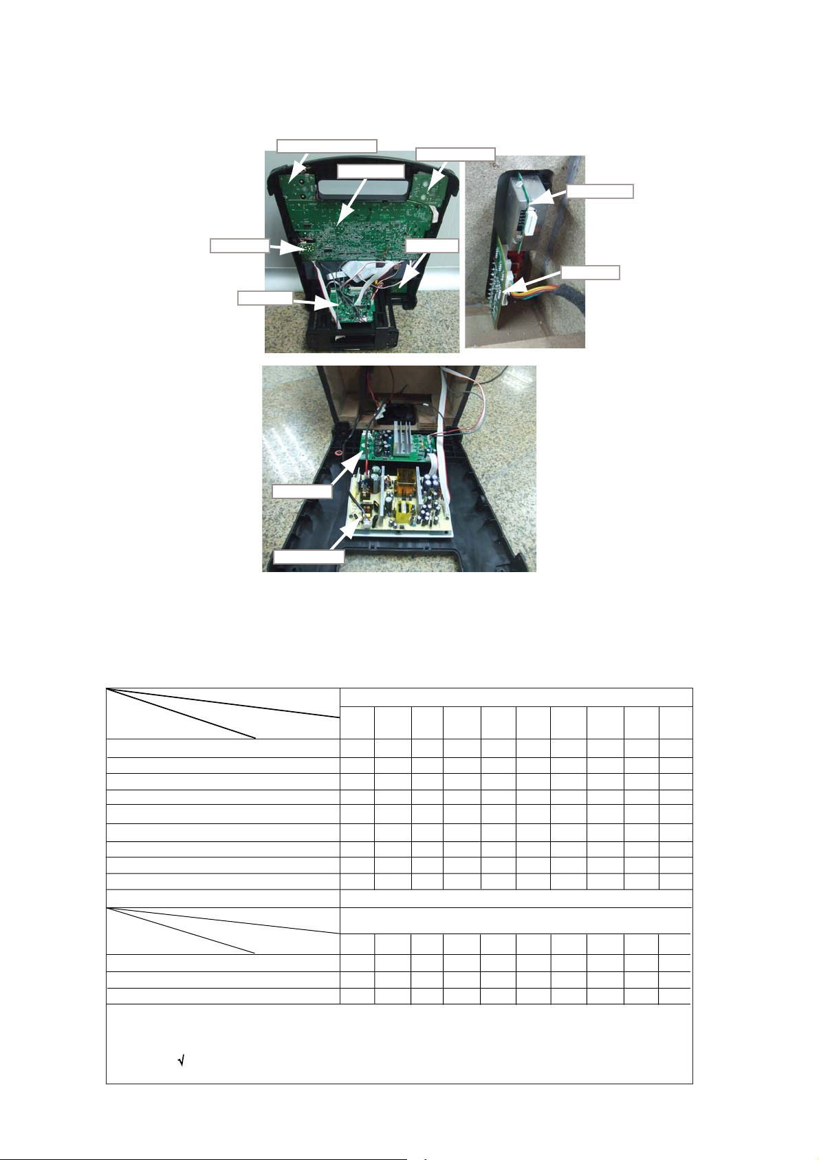
Location of PC Boards
1-2
Technical Specification and Connection Facilities
MIC Board
CD Board
DJ EFFECT Board
Main Board
Amp Board
Volume Board
Tuner Board
BT Board
Jack Board
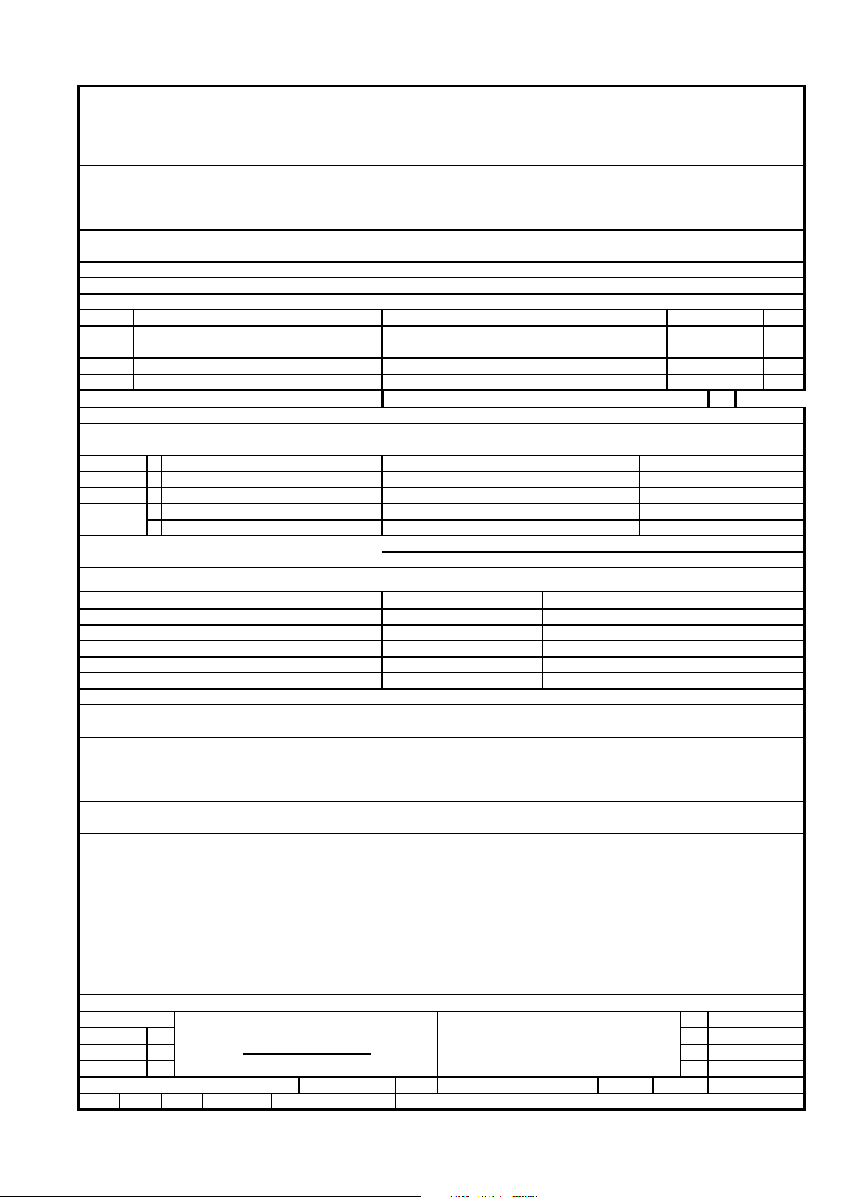
VERSION VARIATION
Type /Versions:
Board in used:
MAIN BOARD
VOLUME BOARD
AMP BOARD
DJ EFFECT BOARD
JACK BOARD
TUNER BOARD
SMPS BOARD
MCU+CD BOARD
Features
RDS
VOLTAGE SELECTOR
ECO STANDBY - DARK
Service policy
Type /Versions:
Feature diffrence
SMPS Board
/77
/55
C+M
C+M
C+M
C+M
C+M
C+M
C+M
C+M
C+M
C+M
C+M
C+M
M
M
C
+M C+M C+M
/55
/77
x/78
C+M
C+M
C+M
C+M
C+M
C+M
M
x/78
NTRX500
/10
C+M
C+M
C+M
C+M
C+M
C
M
+
M
C+M
NTRX500
/10
* TIPS : C -- Component Lever Repair.
M -- Module Lever Repair
-- Used
Page 3
NX5 NX7 ALL SH190 Contact List
No. Descrpitopn Page
*(1(5$/3$57)52173$11(/63(&,&),&$7,21
*(1(5$/3$57%$&.3$11(/63(&,&),&$7,21
*(1(5$/3$57*(1(5$/63(&,&),&$7,21
*(1(5$/3$577(&+1,&$/63(&,&),&$7,21
*(1(5$/3$57$8',26,*1$/63(&,&),&$7,21
*(1(5$/3$57&/2&.7,0(563(&,&),&$7,21
*(1(5$/3$57781(563(&,&),&$7,21$OO
*(1(5$/3$57&'0363(&,&),&$7,21
*(1(5$/3$579(56,2129(59,(:63(&,&),&$7,21
Page 4
1-4
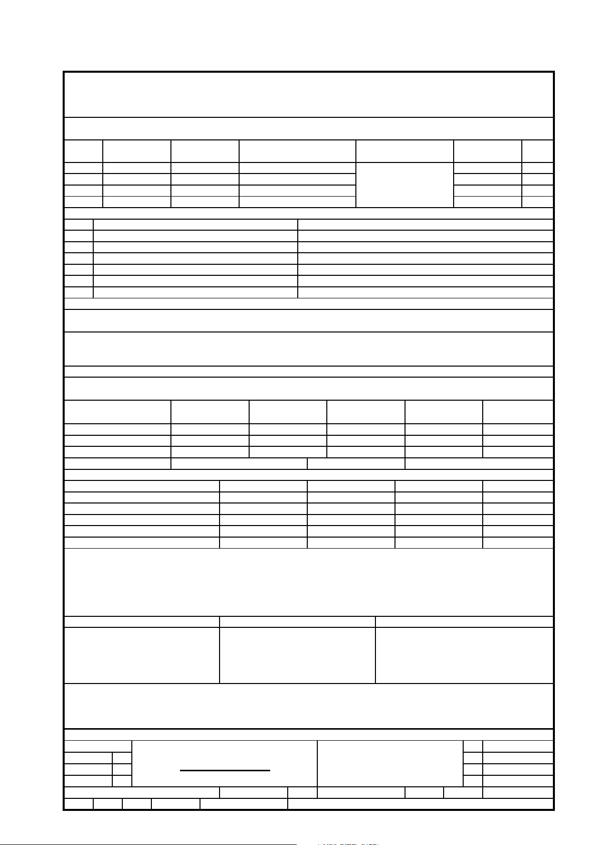
GENERAL DESCRIPTION
MP3-USB Mini Hi FiSystem with Digital Tuner, 1CD/mp3 BT for NX5 NX7 ALL)
(125W x 4 FOR NX5; 239W x 4 FOR NX7 ALL Power Amplifier, LCD Display, Aux in ,
Remote control
LIFETIME : 7 Years
Class Tuner USB Recorder
IX
II X X
III
Page 10
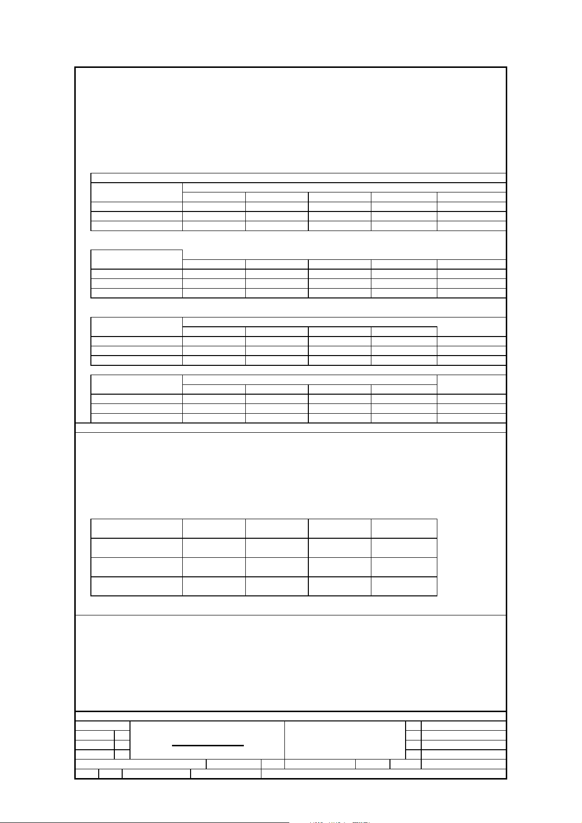
SAFETY requirements
Version Safety EMC
/98 EN 60065 CISPR 13
/55 EN 60065 CISPR 13
/12 EN 60065
/05
/79
/37 UL 60065 FCC99
RADIATION / IMMUNITY requirments ( EMC ) for 12 version only
CLIMATIC requirements
ALL climates
MODERATE climates : + N.A till N.A Degree
PERFORMANCE CLASSES
POWER SUPPLY
MAINS ( A.C. )
Version
Voltage Selection
Frequency
Supply + Amplifier
N/A
3-7 9
EN 55013 / EN 55020
EN 60065 EN 55013 / EN 55020
EN 60065
: + 5 Dregree till + 35 Degree
120 Vac (110V-10%,
120V ±10%)
/ 37
No
60Hz ±5%
230 Vac
± 10 %
/ 12 /05
No
50Hz
127 / 240 Vac
± 15 %
/ 55 /98/96
Yes
60/50Hz
CISPR 13
240 Vac
± 10 %
/ 79
No
50Hz
Clock CD-mp3
X
811
220 Vac
/ 61, /93
60Hz, 50Hz
X
f 10 %
No
POWER CONSUMER
/12 / 55/98/96 /79 /61 /93 / 37
Stadby : < 25W
( DEMO mode " OFF " ) , NOM. A, INPUT
Maximum :
ECO Power mode :
Quality : 0.8 % ( Major ) 2.0 % ( Mirror )
Reliability : 3.0 % ( C 42 )
Tested according to General Test Instruction refer to PHILIPS standary ( UAN -D1591 )
Measured according to PHILIPS standary ( UAN - L1059 ) unless other wise stated
All not mentioned date, please refer to PHILIPS standary ( XUW - 0010 - JUNE 2001 )
DERIVED REMARKS APPROBATION
Remarks
Class No
<110W <110W <110W
<= 1W no <= 1W
GENERAL PART 1 - GENERAL SPECICFICATION
< 25W
NX5 NX7 ALL
NAME : MZ.FENG
KT CHECK
DATE :
10 10
<25W
<130W
Ver
1
2
3
<25W
<110W
<130W@ 1/8 Prated , NOM. A, INPUT <130W <130W
<= 1W
Issued Date
16-4-2013
A4SH 190 - 3
Page 5
1-5
TECHNIAL DESCRIPTION
Total power 500W FOR NX5 1000W FOR NX7 ), FOUR INPUT SOURCE, ( Digital Sound Control ). IS ( Incredible Sound )
GENERAL PART
OUTPUT stage Protection : Yes Temperature : Yes. Shorcircuit : Yes
LoudSpeaker D.C. Protection : Yes.
INDICATORS
Standby Mode Indicator : LCD display Clock active
ECO Mode Indiicator : LCD turns off, ECO - Standby LED turn on
ELECTRICAL DATA
DSC : Rock, Pop, Jazz, Optimal Channel Differencer at -46dB
MAX YES Hum ( Volume Minimun - 50mW )( A - weighted )
IS : YES Residual Noise ( Volume Minium )( A - weighted ) < 100
VAC : N/A Channel Separation ( at 1 kHz )
WOOX : N/A Signal / Noise ( weighted )
Frequency Response ( +/- 3dB ), reference 1kHz 60Hz - 16kHz
INTERCONNECTS
Input Sensitity(
Tuner
CD 0 dB track ( Audio Disc 1, Trk 35 ) Subwoofer Out N.A
USB 0 dB track Headphone
AUX
Microphone :
OUTPUT POWER ( * 1 )
Power output ( RMS ) FOR NX5 ALL Low channel
±2 dB)rated ouput power at 1 kHz and 10kHz.
FM 67.5KHz,AM 80% Modulation - 3dB
:
:
:
:
Nor: 600mV Lim: 450mV ~ 550mV for /37 Digital Coaxial Out N.A
Nor: 2V Lim: 1.5V ~ 2.5V for /55
:
input leven Nor: 1.5mv Lim:0.8-2.5mv
5V RKPRXWSXW 0:
At THD = 10% (Measured with 20Hz-20KHz filter), both channels driven ( Low channel at 1KHz, High channel at 10k )
Line Output Voltage ( *1 )
Line Out ( Left / Right ) N.A
N.A
Booster Out
125W per channel ( Lim '-1dB )˄CD USB AUX˅
High channel
125W per channel ( Lim '-1dB )˄CD USB AUX˅
3
< 200 nW
ı 45
ı 60
N.A
dB
nW
dB
dB
Power output ( RMS ) FOR NX7 ALL Low channel
High channel
Frequency Response
LOW Frepuency Frequency Response - 60Hz - ref. 1kHz ±3 dB
HI Frepuency Frequency Response -6KHz - ref. 10kHz ±3 dB
Rated Impedance
: 3 Ohms
Remarks
( *1 ) Electrical parameters are to be measuremend at specker terminals
with rated input signal in AUX mode; DSC setting in Jazee mode with DBB OFF
IS off and OSM unless specified otherwise
One channel signal input ( L or R ), two channel load ( < Low ch. L + High ch. L > or < Low ch. R + High ch. R > )
Measuremend output power only for AUX model and CD model of used audio analyzer equipment.
GENERAL PART 1 - TECHNAICAL SPECICFICATION
Class No
250W per channel ( Lim '-1dB )˄CD USB AUX˅
250W per channel ( Lim '-1dB )˄CD USB AUX˅
NX5 NX7 ALL
NAME : MZ.FENG
KT CHECK
DATE :
10 10 SH 190 - 4 A4
Ver
1
2
3
Issued Date
16-4-2013
Page 6
AUDIO SIGNAL PROCESSING
MP3-USB Mini Hi Fi System with Digital Tuner ,Class AB Power Amplifier
1 ) DSC ( Digital Sound Control )
Select AUX as input source with the following set conditions:
Inject sine wave 2V at 1 KHz to L/R channels of AUX-IN socket.
Set DSC to JAZZ(Flat) mode and switch off DBB. Max off
Refence level for DSC's without DBB on=500mW.
Refence level for DSC'S with DBB on=1.7V at the speaker terminal .
Inject sine wave 2V to AUX-IN socket with frequencies indicated in Table 1.
1-6
Tabel 1a ( Tolerance ± 3dB )
Frequency
60 Hz -1.8 dB + 3 dB + 6dB +0.5dB
1 kHz
10 kHz
Tabel 1b ( Tolerance ± 3dB )
Frequency
60 Hz +3 dB +8dB
1 kHz 0 dB +1 dB 1 dB
Tabel 1b ( Tolerance ± 3dB )
Frequency
1 kHz
10kHz -1.5 dB
Tabel 1b ( Tolerance ± 3dB )
Frequency
60 Hz
1 kHz +0dB +1dB +1dB
10 kHz -0.5 dB + 2dB +3dB + 1dB
JAZZ POP ROCK
0 dB 0.5db
-1.5 dB -0.6dB +1 dB -0.5 dB
JAZZ POP ROCK TECHNO
JAZZ POP ROCK
+0 dB
JAZZ
+14 dB
+ 14.0 dB
+1dB
DSC Modes with DBB 3 ON
POP
+ 17.0 dB + 20.0 dB
DSC Modes with DBB Off
1 dB
DSC Modes with DBB 1 ON
+ 14DŽ5dB
DSC Modes with DBB 2 ON
+ 15.0 dB60 Hz +8dB
+1 dB +1 dB
+2 dB
ROCK
TECHNO
0.5dB
5.5 dB
+1 dB
-0.5dB 10 kHz -1.5 dB +-0.6dB +1dB
TECHNO
+ 11.0 dB
- 0.5dB + 1dB
TECHNO
+ 18.0 dB
+1 dB
SAMBA
+0.3dB
0
-3
SAMBA
+5.5dB
0
-3
SAMBA
+11dB
0
-0.5
SAMBA
+18dB
0
1
Class No
NAME : MZ.FENG DATE:25/08/07
KT CHECK
GENERAL PART 1 - GENERAL SPECICFICATION
NX5 NX7 ALL
10 10 SH 190 - 5
DATE :
Ver
1
2
3
Issued Date
16-4-2013
A4
Page 7
1
AUDIO SIGNAL PROCESSING
MP3 - USB Mini Hi Fi System with Digital Tuner , 1CDCfor NX5 NX7 ALL
3 ) IS ( Incredible Sound )
Select AUX as input source.
Inject sine wave 2V at 1kHz to AUX-IN socket, one channel at a time (input level 500mV for /37,2V for /55 ).
Set DSC to JAZZ ( Flat ) mode and switch of DBB, OSM & INCREDIBLE SURROUND.
Adjust volume level to obtain 500mW across 4OHM load at L/R speaker output.
Inject sine wave 2V to AUX-IN socket withfrequency indicated in Table 3 (input level 500mV for /37,2V for /55 ).
Right channel reference to left channel.
Table 3 ( Tolerence ± 3 dB )
FREQ
1 kHz + 3.5 dB -0 dB
10 kHz 2V - - 0.5 dB
Note : The above specs also apply to right channel.
4 ) DSC Mode ( Jazz , Rock, Techno and Optimal )
The VEC modes are software controlled by switching the combination between DBB and DSC modes
as show in Table 4.
DSC MODE
Jazz
POP
Techno DBB 3
Optimal
Note : When these modes are activ DBB and DSC will not be displayed
5 ) MAX ( Maximum Sound )
INPUT LEVEL
LEFTRIGHTLEFTRIGHT
2V60 Hz - - 1.0 dB -
2V - 0 -
DBB Level preset
DBB OFF
DBB 2
DBB 1
IS OFF IS ON
OUTPUT LEVEL
- + 3.0 dB -7.0 dB
LEFT RIGHT
+2.0 dB -17.0 dB
Select AUX as input source.
Inject sine wave 2V at 1kHz to AUX-IN socket, one channel at a time (input level 600mV for /37,2V for /55 ).
Set DSC to JAZZ ( Flat ) mode and switch of DBB, OSM & INCREDIBLE SURROUND.
Adjust volume level to obtain 500mW load at L/R speaker output.
The 500mW level will be used as 0 dB reference
Inject sine wave 2V to AUX-IN socket withfrequency indicated in Table 5 (input level 600mV for /37,2V for /55 ).
FREQ
60 Hz
1 kHz
10 kHz
Class No
Max OFF Max ON
00 dB + 19 .0 dB
0 + 7.0 dB
- 0.5 dB + 10.0 dB
GENERAL PART 1 - AUDIO SIGNAL SPECICFICATION ( 2 )
NX5 NX7 ALL
NAME : MZ.FENG 10
KT
CHECK DATE :
Ver Issued Date
2
16-4-2013
3
A410 SH 190 - 6
Page 8
1-8
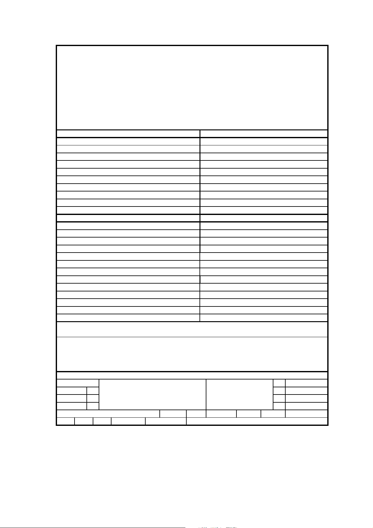
TECHNIAL DESCRIPTION
AUX modle
GENERAL PART
Description Specification
Output power = , 1 Khz )
Channel Unbalance < = +/- 3 dB
THD + Noise ( 0dB, 1Khz ) <=2%
Channel Crosstalk ( ( 0dB, 1 KHz ) >= 40dB
( 0 dB, 10 KHz )
Signal to Noise Ratio ( 0dB,1kHz ) ( A - weighted ) >= 60dB( A - weighted )
Frequency Response ( +/- 3dB ), reference 1kHz
Microphone
Description Specification
Output power = , 1 Khz 2mV input) 1W± 1 dB
THD + Noise ( 0dB, 1Khz ) <=5%
Signal to Noise Ratio ( 0dB,1kHz ) ( A - weighted ) >= 45dB( A - weighted )
Frequency Response ( +/- 3dB ), reference 1kHz 100Hz - 16kHz
125W± 1 Db(NX5) 250W± 1 Db(NX7)
>= 40dB
60Hz - 16kHz
Remarks :
Class No
NAME : MZ.FENG
NX5 NX7 ALL
CHECK
DATE :
USB SPECICFICATION
10 10 SH 190 -9
Ver
1
2
3
Issued Date
16-4-2013
A4
Page 9
1-9
TECHNIAL DESCRIPTION
SOFTWARE IMPLEMENTED CLOCK / TIMER FUNCTION WITHOUT 32.768KHZ QUARTZ OSCILLATOR.
GENERAL PART
Timer Setting : Clock and Timer
Timer Wakeup Mode
Remarks Time Setting : 12hr for /37 version, 24hrs for other version.
Volume at Wakeup : Last Setting
1RRI7LPHU6HWWLQJV : 1
&ORFN$FFXUDF\ : Nom : 1 sec/day Limit : 2 sec/day
,1',&$7256
'LVSOD\7\SH
Remark
: CD USB or Tuner
/&'
CLOCK / TIMMER SPECICFICATION
Class No
NX5 NX7 ALL
NAME : MZ.FENG 10
KT CHECK
DATE :
Ver Issued Date
1
2
3
10 SH 190 - 7 A4
16-4-2013
Page 10

1-10
TECHNIAL DESCRIPTION
USB
See also SH 190 USB Audio Module (300605)
Measurment are directly done at the coonector on the board
GENERAL PART
Measurement are directly done at the connector on CDC board
Description Specification
Output Resistance < = 1.5 kOhm
Output Voltage RL = 33 k ohm dB, 1 Khz NC
Channel Unbalance < = +/- 1 dB
THD + Noise ( 0dB, 1Khz ) <=1.5%
Channel Crosstalk (1k) >= 40dB
( 0 dB, 10 KHz )
Signal to Noise Ratio ( 0dB,1kHz ) ( A - weighted ) >= 60dB( A - weighted )
Frequency Response ( +/- 3dB ), reference 1kHz 60Hz - 16kHz
>= 40dB
USB Measurement at Set Level
Electrical Parameters are to be measured at speaker teminals across 6 ohm load with 500mW output and DSC setting in Jazz Mode
Description Specification
Channel Crosstalk ( 0 dB, 1 KHz ) >= 40dB (with 1 KHz filter )
Signal to Noise Ratio ( 0 dB, 1 KHz ) >= 60dBA ( A - weighted )
Channel Unbalance ( 0 dB, 1 KHz ) < +/- 1.5dB
Frequency Response ( +/- 3dB ), reference 1kHz 60Hz - 5.8kHz
Frequency Response ( +/- 4dB ), reference 10kHz 6KHz - 16kHz
Remarks :
USB SPECICFICATION
Class No
NAME : MZ.FENG
NX5 NX7 ALL
CHECK
DATE :
10 10 SH 190 -8
Ver Issued Date
1
16-4-2013
2
3
A4
Page 11

1-11
V
V
G
TECHNIAL DESCRIPTION
GENERAL PART
WAVE RANGE TOLERANCE TUNING GRID
FM( 55/37 ) 87.5 - 108.00 MHz QUARTZ PRECISION 100 kHz
FM( 12 ) 87.5 - 108.00 MHz 50KHZ
AM (55/37) 530 - 1700 kHz QUARTZ PRECISION 10 kHz
AM (12) 531 - 1602 kHz QUARTZ PRECISION 9 kHz
AERIAL
FM : PIGTAIL ANT WIRE 300 Ohm(for/37) 75ohm for 55/12
AM : FRAME ANT. 18.1 uH
INDICATORS
L
CD
ELECTRICAL DATA
A.M
Amplification Reverse
AGC Figure of Merit
Distortion ( RF 50mV, M 80% )
IF
Modulation Hum.
Nom Limit
: - 2 -4 dB
: 30 25 dB
: 3 5 %
: 450 ± 3 kHz 18
35 30 dB
Unit
Wave Range Noise Limited Sensitivity 26 dB
MW 610 kHz
MW 1400 kHz
FM 98 MHz
MW 610 kHz
MW 1400 kHz
FM 98 MHz
Nom.
Lim.
Nom.
Lim.
Nom.
Lim.
Nom.
Lim.
Nom.
Lim.
Nom.
Lim.
3500
4000
1500
uV/m 32 db
Uv/m 28db
uV/m
4000 uV/m 28db 24db 500mv/m
18
dBf 40db 65db 116 dBu
22 dBf 30db 60db 108 dBu
Auto Search sensitivity
58
db/m
± 10 db/m
58
db/m
± 10 db/m
26
dBu
± 10 dBu
Remarks
F.M.
- 3 dB Limiting Point
Amplification Reverse
Distortion ( RF 1mV, Frq Dev.75 kHz )
Stereo - 46 dB Quieting
Crosstalk (RF1mV, Freq Dev.40kHz )
Modulation Hum.
Image Rejection
IF Rejection Large Signal
24db
32db 28db 1000mv/m
Nom Limit Unit
: 17 23.5 dBf
: 0 -4 dB
: 2 5 %
: 38 43
: 25
dBf
dB
45 40 dB
Selectivity
S3 / S9 / 300kHz
22db28db 1000mv/m
500mv/m
18db
22db
18db
45db
25db
TUNER SPECICFICATION
Class No
NX5 NX7 ALL
Ver Issued Date
1
16-4-2013
2
3
NAME : MZ.FEN
KT
CHECK
DATE :
10 SH 190 - 9
A410
Page 12

TECHNIAL DESCRIPTION
GENERAL PART
Bluetooth Version : Ver2.1 + EDR
Receive A2DP: N/A
Transmit A2DP: N/A
Receive HSP N/A
INDICATORS
1-12
Bluetooth Function
Remote Controlled :
Noise Reduction System :
YES
No
Bluetooth Flashing : Yes
Display :
ELECTRICAL DATA
Bluetooth at Module level: Mobile Phone lim Unit
Frequency Response 125-16khz f
S/N (Unweighted) ı
S/N (A-weighted) ı dBA
Level Diff ? f
Channel Separation ı dB
Distortion ˘
Bluetooth at Set Level Mobile Phone
10%THD OUTPUT POWER(EQ:FLAT) \ 250± 3dB W
Connected distance 8~10 meter
Yes
dB
dB
dB
λ
REMARKS
Bluetooth SPECICFICATION
Class No
NX5 NX7 ALL All Version
NAME : TAN DATE : SH 190 - 9
CHECK: DATE :
Ver Issued Date
1
2
3
16-4-2013
Page 13

1-13
t
t
r
r
TECHNIAL DESCRIPTION
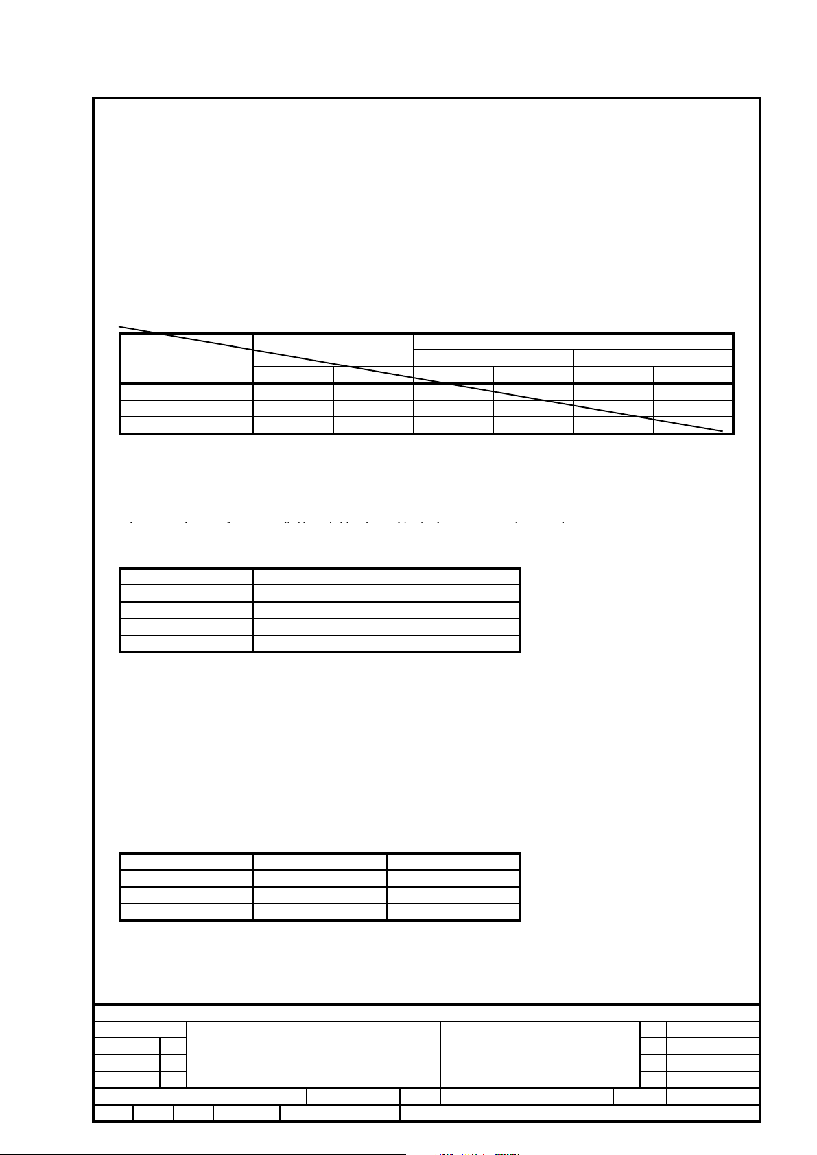
CD + MP3 - Part Specifications (CD MECHAISM DA11VF OF SANYO ) 1DISC for NX5 NX7 ALL
Inpu
Active components %8
Signal processsing D/A converte
Outpu
%8
Motor Logic control
SA5888
HF-preamplifie
Servo processor
BU9543
Active components BU9543 BU9543 NA DA23SR
AUDIO part: Measurement with Audio Signals Disc TCD-781 on spkeakers or Headphone socket with nom.load
Description
De-emphasis
Frequency accuracy N/A ± 0.5 %
Channel Unbalance 0.5 1.5
Frequency Response ( 60Hz - 16 kHz ) 0 ± 3 dB
Signal to Noise Ration ( Unweighted ) 60 55
Signal to Noise Ration ( A - weighted ) 65 60 dBA
Crosstalk ( 1kHz ) ( A - weighted ) 55 40
Crosstalk ( 10KHz ) ( A - weighted ) 50 40 dB
Hum & Noise ( *1 ) 12
THD (1KHz -6dB) 0.2 <1.5 %
REMARKS:
1. Amplification reserve for CD = +2dB ('±2dB),Ref.Level for CD is a 0dB track instead of a .-6dB track.
Extern
15us / 50us Switchable via Subcode information
Nom Lim
Unit
dB
dBA
dB
Mv
%THD (10KHz -20dB) <1 <1.5
Playability :(acc.To AR 30-05-239 )
Limit Typical Test disc
Wedge 600um 900um TNO 7, 9 of SBC 444A(7104 099 24990)
Eccentric 150um 200um TNO 1, 24 of 200um disc (7104 099 24960)
Fingerprint No audible defect TNO 11 of Sub chassis 8A
Black dot 500um 800um TNO 13 of SBC 444A (7104 099 24990)
Skew 0.6mm No audible defect TNO 1,6 of 0.6mm skew (7104 099 28260)
Bad HF track No audible defect TNO 8 of Sub chassis 8A
Playback position Solid, Normal position (Set is located on a flat surface, floor)
1. Playback of above mentioned tracks possible wihout track loss or audible defects.
2. Double black dot, max. diameter, thin/disk is according to PQR or AR 30-05-239
3. This unit can playback (only) CD-R or CD-RW discs. For performance specification, Please refer to module.
specification of CD99 (3103 308 52190)
CD / MP3 SPECICFICATION
1
2
3
Issued Date
16-4-2013
Class No
NAME : MZ.FENG
KT CHECK
Ver
NX5 NX7 ALL
10 10 SH 190 -10
DATE :
A4
Page 14

1-14
VERSION OVERVIEW (NX5 NX7) ALL
Ver DEST
/55 /98 OVS
/05 / 12 EUROPE
/79 AUST / NZ
/37
/35 China
/ 33 Korea
USA
Canada
APPROBATION TUNER AC SUPPLY
SAFETY EMC
EN60065
CLASS II
SISR
TAIWAN
EN60065
SEMKO
DEMKO
NEMKO SEV
BS415-UK
EN60065
CLASS II
UL 6500 FCC 99
EN60065
CLASS II
EN60065
CLASS II
CISPR 13
EN55013
EN55020
Wave RANGE GRID CORD
FM 87.5-108MHz MW
531-1602kHz
or 530-1710kHz
FM 87.5-108MHz MW
531-1602kHz
FM 87.5-108MHz MW
531-1602kHz
FM 87.5-108MHz MW
530-1710kHz
FM 87.5-108MHz MW
531-1602kHz
FM 87.5-108MHz MW
531-1602kHz
50kHz
9kHz
10kHz
50kHz
9kHz
50kHz
9kHz
100kHz
10kHz
50kHz
9kHz
50kHz
9kHz
75 Ohm Coaxial
JST XH 2P Side
75 Ohm Coaxial
JST XH 2P Side
75 Ohm Coaxial
JST XH 2P Side
JALCO Click Fit
JST XH 2P Side
75 Ohm Coaxial
JST XH 2P Side
75 Ohm Coaxial
JST XH 2P Side
75 Ohm Pigtail
Loop Sagami 18.1uH
75 Ohm Pigtail
Loop Sagami 18.1uH
75 Ohm Pigtail
Loop Sagami 18.1uH
300 Ohm Dipole
Loop Sagami 18.1uH
75 Ohm Pigtail
Loop Sagami 18.1uH
75 Ohm Pigtail
Loop Sagami 18.1uH
MAINS
VOLTAGE
110-127V
Switched
220 - 240V
50/60Hz
230V
50Hz
240V
50Hz
120V
60Hz
220V
60Hz
220V
60Hz
SOC.AERIAL SOCKET AERIAL SUPPLIED
IEC IEC
IEC
IEC IEC
UL
IEC IEC
IEC
IEC
UL
IEC
MIC
MIX
No
No
No
No
No
No
MAT
RIX
SURR
. SPK.
No
No
No
No
No
No
Class No
NX5 NX7 ALL
NAME : MZ.FENG
KT CHECK DATE :
VERSION OVERVIEW
10 SH 190 - 1110 A4
Ver
1
2
3
Issued Date
16-4-2013
Page 15

2.Safety instruction
1. General safety
Safety regulations require that during a repair:
. Connect the unit to the mains via an isolation transformer.
. Replace safety components indicated by the symbol
components identical to the original ones. Any
only by
other component substitution (other than original type)
may increase risk of fire or electrical shock hazard.
Safety regulations require that after a repair, you must
return the unit in its original condition. Pay, in particular,
attention to the following points:
. Route the wires/cables correctly, and fix them with the
mounted cable clamps.
. Check the insulation of the mains lead for external
damage.
. Check the electrical DC resistance between the mains
plug and the secondary side:
1) Unplug the mains cord, and connect a wire between
the two pins of the mains plug.
2) Set the mains switch the “on” position (keep the
mains cord unplug).
3) Measure the resistance value between the mains
plug and the front panel, controls, and chassis
bottom.
4) Repair or correct unit when the resistance
measurement is less than 1M
5) Verify
6) Switch the unit “off”, and remove the wire between
this, before you return the unit to the
customer/user (ref. UL-standard no. 1492).
the two pins of the mains plug.
¡
.
,
2.Laser safety
This unit employs a laser. Only qualified service personnel
may remove the cover, or attempt to service this device
(due to possible eye injury).
Laser device unit
Type : Semiconductor laser GaAlAs
Wavelength : 650nm (DVD)
: 780nm (VCD/CD)
Output power : 7mW (DVD)
: 10mW (DVD /CD)
Beam divergence: 60 degree
Note: Use of controls or adjustments or performance of
procedure other than those specified herein, may result in
hazardous radiation exposure. Avoid direct exposure to
beam.
Page 16

BLOCK DIAGRAM
3-1 3-1
Page 17

WIRING DIAGRAM
4-1 4-1
Page 18

OUTER
1) Remove 46 screws A/B/C/D/E/F/G as indicated to loosen the top/front/bottom plate.
A
C D E
B
Dismantling of the CD part and PCB Board
1) Remove 8 screws H&I as indicated to loosen the CD part.
2) Remove 4 screws J as indicated to loosen the CD Board.
4) Remove 13 screws K and 8 screws L as indicated to loosen the Main Board.
5) Remove 4 screws M as indicated to loosen the Smps power Board.
6) Remove 6 screws N as indicated to loosen the Amp Board.
F
G
H
K
I
J
L
M
N
Page 19

CIRCUIT DIAGRAM - MAIN BOARD AND JACK BOARD
Page 20

6-2 6-2
Page 21

6-3 6-3
Page 22

PCB LAYOUT - MAIN BOARD
6-4
6-4
Page 23

PCB LAYOUT - JACK BOARD
6-5
6-5
Page 24

CIRCUIT DIAGRAM - AMP BOARD
7-1
7-1
Page 25

PCB LAYOUT - AMP BOARD
7-2
7-2
Page 26

8-1
CIRCUIT DIAGRAM - MCU BOARD AND CD BOARD
8-1
Page 27

8-2
CIRCUIT DIAGRAM - MCU BOARD AND CD BOARD
8-2
Page 28

PCB LAYOUT - MCU + CD BOARD
8-3
8-3
Page 29

PCB LAYOUT - MCU + CD BOARD
8-4
8-4
Page 30

EXPLODED VIEW
9-1 9-1
 Loading...