

Philips N74F161AN, N74F163AN, N74F163AD, N74F161AD Datasheet

INTEGRATED CIRCUITS
74F160A*, 74F161A,
74F162A*, 74F163A
4-bit binary counter
* Discontinued part. Please see the Discontinued Product List in Section 1, page 21.
Product specification 1996 Jan 29
IC15 Data Handbook
Philips Semiconductors Product specification
DRAWING
74F161A, 74F163A4-bit binary counters
FEA TURES
•Synchronous counting and loading
•Two count enable inputs for n-bit cascading
•Positive edge-triggered clock
•Asynchronous Master Reset (74F161A)
•Synchronous Reset (74F163A)
•High speed synchronous expansion
•Typical count rate of 130MHz
•Industrial range (–40°C to +85°C) available
DESCRIPTION
4-bit binary counters feature an internal carry look-ahead and can be
used for high-speed counting. Synchronous operation is provided by
having all flip-flops clocked simultaneously on the positive-going
edge of the clock. The clock input is buffered.
The outputs of the counters may be preset to High or Low level. A
Low level at the Parallel Enable (PE
action and causes the data at the D0–D3 inputs to be loaded into
the counter on the positive-going edge of the clock (provided that
the setup and hold requirements for PE
regardless of the levels at Count Enable (CEP, CET) inputs.
) input disables the counting
are met). Preset takes place
A Low level at the Master Reset (MR
of the flip-flops (Q0 – Q3) in 74F161A to Low levels, regardless of
the levels at CP, PE, CET and CEP inputs (thus providing an
asynchronous clear function). For the 74F163A, the clear function is
synchronous. A Low level at the Synchronous Reset (SR
all four outputs of the flip-flops (Q0 – Q3) to Low levels after the next
positive-going transition on the clock (CP) input (provided that the
setup and hold time requirements for SR
occurs regardless of the levels at PE
synchronous reset feature enables the designer to modify the
maximum count with only one external NAND gate (see Figure 1).
The carry look-ahead simplifies serial cascading of the counters.
Both Count Enable (CEP and CET) inputs must be High to count.
The CET input is fed forward to enable the TC output. The TC
output thus enabled will produce a High output pulse of a duration
approximately equal to the High level output of Q0. This pulse can
be used to enable the next cascaded stage (see Figure 2). The TC
output is subjected to decoding spikes due to internal race
conditions. Therefore, it is not recommended for use as clock or
asynchronous reset for flip-flops, registers, or counters.
TYPE
74F161A
74F163A
TYPICAL
f
MAX
130MHz 46mA
) input sets all the four outputs
) input sets
are met). This action
, CET, and CEP inputs. The
TYPICAL SUPPL Y CURRENT
(TOTAL)
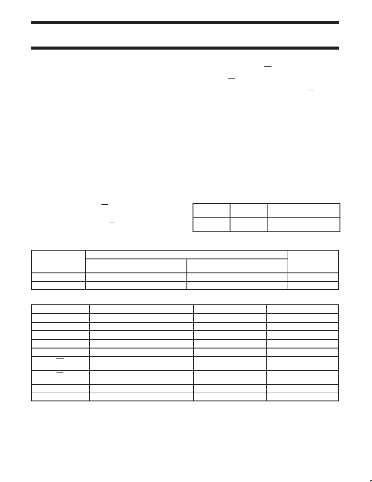
ORDERING INFORMATION
ORDER CODE
DESCRIPTION
16-pin plastic DIP N74F161AN, N74F163AN I74F161AN, I74F163AN SOT38-4
16-pin plastic SO N74F161AD, N74F163AD I74F161AD, I74F163AD SOT109-1
COMMERCIAL RANGE
VCC = 5V ±10%, T
= 0°C to +70°C
amb
VCC = 5V ±10%, T
INDUSTRIAL RANGE
= –40°C to +85°C
amb
INPUT AND OUTPUT LOADING AND FAN-OUT TABLE
PINS DESCRIPTION 74F (U.L.) HIGH/LOW LOAD VALUE HIGH/LOW
D0 – D3 Data inputs 1.0/1.0 20µA/0.6mA
CEP Count Enable Parallel input 1.0/1.0 20µA/0.6mA
CET Count Enable Trickle input 1.0/2.0 20µA/1.2mA
CP Clock input (active rising edge) 1.0/1.0 20µA/0.6mA
PE Parallel Enable input (active Low) 1.0/2.0 20µA/1.2mA
MR Asynchronous Master Reset input
(active Low) for 74F161A
SR Synchronous Reset input
(active Low) for 74F163A
TC T erminal count output 50/33 1.0mA/20mA
Q0 – Q3 Flip-flop outputs 50/33 1.0mA/20mA
NOTE:
One (1.0) FAST unit load is defined as: 20µA in the High state and 0.6mA in the Low state.
1.0/1.0 20µA/0.6mA
1.0/1.0 20µA/0.6mA
NUMBER
1996 Jan 29 853–0347 16300
2
Philips Semiconductors Product specification
74F161A, 74F163A4-bit binary counters
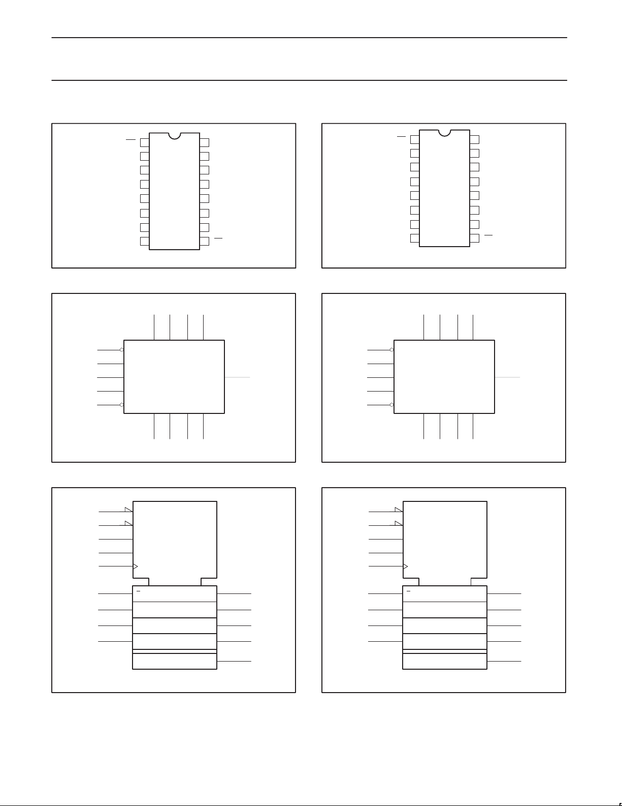
74F161A PIN CONFIGURA TION
MR
1
CP
2
D0
3
D1
4
D2
5
D3
6
CEP
74F161A LOGIC SYMBOL
34
9
7
10
2
1MR
PE
CEP
CET
CP
Q0 Q1
56
D1 D2
Q2 Q3
16
V
CC
TC
15
Q0
14
Q1
13
Q2
12
Q3
11
CET
107
98GND PE
SF00656
D3D0
TC 15
74F163A PIN CONFIGURA TION
SR
1
CP
2
D0
3
D1
4
D2
5
D3
6
CEP
74F163A LOGIC SYMBOL
34
9
7
10
2
1SR
PE
CEP
CET
CP
Q0 Q1
56
D1 D2
Q2 Q3
16
V
CC
TC
15
Q0
14
Q1
13
Q2
12
Q3
11
CET
107
98GND PE
SF00657
D3D0
TC 15
= Pin 16
CC
GND = Pin 8
14 13
12 11V
74F161A LOGIC SYMBOL (IEEE/IEC)
1
9
7
10
2
3
4
5
6
R
M1
G3
G4
C2 /1,3,4+
,2 D
1
CTR DIV 16
4 CT=15
SF00658
SF00660
= Pin 16
CC
GND = Pin 8
14 13
12 11V
SF00659
74F163A LOGIC SYMBOL (IEEE/IEC)
1
9
7
10
2
14
13
12
11
15
3
4
5
6
2R
M1
G3
G4
C2 /1,3,4+
,2 D
1
CTR DIV 16
4 CT=15
14
13
12
11
15
SF00661
1996 Jan 29
3
Philips Semiconductors Product specification
OPERATING MODE
Parallel load
Hold (do nothing)
74F161A, 74F163A4-bit binary counters
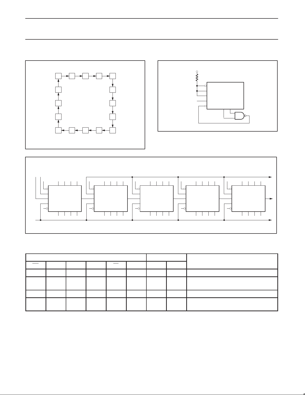
STATE DIAGRAM
0 1 2 3
15
14
13
12 11 10 9
H H = Enable count
or
L L = Disable count
PE
CEP
CET
CP
SR
Q0 Q1 Q2 Q3
APPLICATIONS
+V
CC
4
D1 D2
5
6
7
8
CLOCK
PE
CEP
CET
CP
SR
Q0 Q1 Q2 Q3
Figure 1. Maximum count modifying scheme
Terminal count = 6
SF00664
D1 D2 D3D0
TC74F163A
PE
CEP
CET
CP
SR
Q0 Q1 Q2 Q3
D1 D2 D3D0
TC74F163A
PE
CEP
CET
CP
SR
Q0 Q1 Q2 Q3
D1 D2 D3D0
TC74F163A
PE
CEP
CET
CP
SR
Q0 Q1 Q2 Q3
D1 D2 D3D0
TC74F163A
D3D0
TC74F163A
SF00665
PE
CEP
CET
CP
SR
Q0 Q1 Q2 Q3
D1 D2
D3D0
TC74F163A
CP
Figure 2. Synchronous multistage counting scheme
74F161A MODE SELECT – FUNCTION TABLE
INPUTS OUTPUTS
MR CP CEP CET PE Dn Qn TC
L X X X X X L L Reset (clear)
H ↑ X X l l L L
H ↑ X X l h H (1)
H ↑ h h h X count (1) Count
H X l X h X q
H X X l h X q
n
n
(1)
L
SF00666
1996 Jan 29
4
Philips Semiconductors Product specification
OPERATING MODE
Parallel load
Hold (do nothing)
74F161A, 74F163A4-bit binary counters
74F163A MODE SELECT – FUNCTION TABLE
INPUTS OUTPUTS
SR CP CEP CET PE Dn Qn TC
l ↑ X X X X L L Reset (clear)
h ↑ X X l l L L
h ↑ X X l h H (2)
h ↑ h h h X count (2) Count
h X l X h X q
h X X l h X q
n
n
H = High voltage level
h = High voltage level one setup prior to the Low-to-High clock transition
L = Low voltage level
l = Low voltage level one setup prior to the Low-to-High clock transition
= Lower case letters indicate the state of the referenced output prior to the Low-to-High clock transition
q
n
X = Don’t care
↑ = Low-to-High clock transition
(1) = The TC output is High when CET is High and the counter is at Terminal Count (HHHH for 74F161A)
(2) = The TC output is High when CET is High and the counter is at Terminal Count (HHHH for 74F163A)
(2)
L
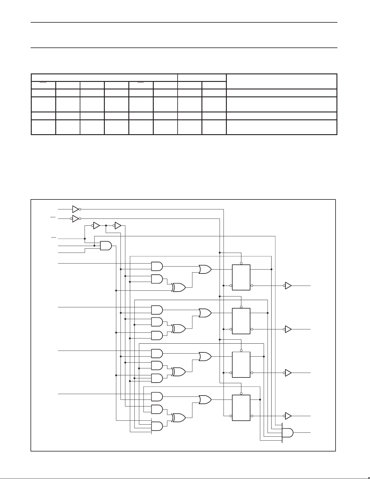
74F161A LOGIC DIAGRAM
2
CP
1
MR
9
PE
10
CET
7
CEP
3
D0
4
D1
5
D2
R
DCPQ
R
DCPQ
R
DCPQ
14
Q
Q
Q
Q0
13
Q1
12
Q2
VCC = Pin 16
GND = Pin 8
1996 Jan 29
6
D3
R
DCPQ
11
15
SF00662
Q3
TC
Q
5
 Loading...